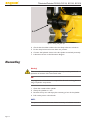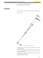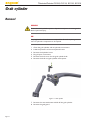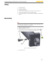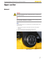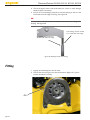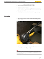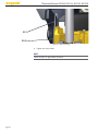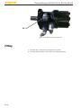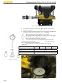
1
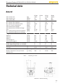
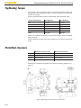
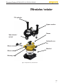
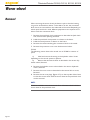
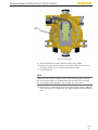
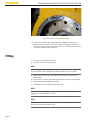
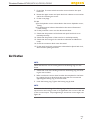
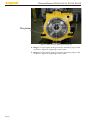
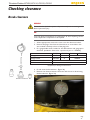
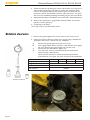
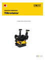
SERVICE MANUAL
Tiltrotator
EC209 | EC214 | EC219 | EC226
Version | 201401
Part no. | 922004
Tiltrotator/Rotator EC209, EC214, EC219, EC226
Contents
About this service manual............................................................. 4
Safety instructions........................................................................... 5
General........................................................................................ 5
Warnings..................................................................................... 5
Technical data................................................................................... 7
General........................................................................................ 7
A.................................................................................................... 8
B..................................................................................................... 8
Tightening torque...................................................................... 8
Permitted clearance.................................................................. 8
Tilt cylinder..................................................................................... 10
Removal..................................................................................... 10
Adjustment................................................................................ 11
Fitting.......................................................................................... 13
Dismantling............................................................................... 14
Assembly.................................................................................... 15
Grab cylinder.................................................................................. 16
Removal..................................................................................... 16
Fitting.......................................................................................... 17
Dismantling............................................................................... 17
Assembly.................................................................................... 18
Hydraulic valves............................................................................. 20
Removal..................................................................................... 20
Replacing the electromagnet................................................. 20
Fitting.......................................................................................... 21
Upper section................................................................................. 23
Removal..................................................................................... 23
Fitting.......................................................................................... 24
Shimming................................................................................... 25
Hydraulic motor............................................................................ 27
Removal..................................................................................... 27
Adjustment................................................................................ 27
Fitting.......................................................................................... 28
worm screw.................................................................................... 29
Removal..................................................................................... 29
Fitting.......................................................................................... 29
Worm wheel.................................................................................. 32
Removal..................................................................................... 32
Fitting.......................................................................................... 34
Verification................................................................................ 35
Checking clearance....................................................................... 37
Break clearance........................................................................ 37
Rotation clearance.................................................................. 38
Page
3
Tiltrotator/Rotator EC209, EC214, EC219, EC226
About this service manual
The purpose of this service manual is to describe how various repair and servicing operations are carried out so
that the risk of injuries or damage to equipment can be avoided as far as possible. The scope and order of various work elements may vary depending on the tiltrotator, control system, quick hitch lock and service action in
question.
For more detailed descriptions in the form of exploded diagrams, wiring diagrams and a spare parts catalogue,
please see our website at www.engcon.com.
Page 4
Tiltrotator/Rotator EC209, EC214, EC219, EC226
Safety instructions
General
Symbol descriptions
The expressions WARNING!, NB! and NOTE: have the following meanings in this service manual:
WARNING!
"Warning" is used if an incorrect procedure could lead to injury.
NB!
"NB" is used if an incorrect procedure could cause damage to property.
NOTE:
"Note" is used to give important instructions to the user.
The service manual describes the repairs and inspection measures required for tiltrotator/rotator EC209, EC214, EC 219 and EC226.
The safety instructions are independent of the base machine.
Also observe the safety information provided for the base machine and
any other equipment.
See also the safety instructions in the instruction manual.
It is of the utmost importance that you study and understand all the warning texts before servicing commences. The warning texts highlight potential risks and how to avoid them.
If in the slightest doubt, contact your employer or supplier. Good judgement reduces many unnecessary risks.
Warnings
WARNING!
Incorrect fitting can imply a safety risk. If in the slightest doubt - contact a
dealer or engcon Nordic AB.
WARNING!
Ensure that the hydraulic system is depressurised prior to beginning any
work on the system. Risk of personal injury.
Page
5
Tiltrotator/Rotator EC209, EC214, EC219, EC226
WARNING!
De-energise the electrical system. Remove rings, watches etc., before
starting work. Risk of personal injury.
WARNING!
Never use your hands to investigate a leak in the hydraulic system. Risk of
personal injury, as pressurised hydraulic oil can penetrate the skin.
WARNING!
Tools connected to the tiltrotator/rotator may only be used if locking has
been correctly performed. ALWAYS ensure that the locking bolts are
forced out as per the specification for the quick hitch coupler concerned.
WARNING!
Never attempt to increase the maximum capacity of the equipment
through modifications not authorised by the supplier.
WARNING!
Short-circuits in electrical cabling may entail risks of personal injury and
fire. Exercise caution concerning insulation of electrical conductors and
components when installing/fitting electrical equipment.
WARNING!
Risk of burns on contact with hot hydraulic oil.
WARNING!
The machine may be operated with the switch for quick hitch lock in the
activated position only with the joint deactivation of the bucket or tool.
WARNING!
If you have the slightest doubt concerning your knowledge or work regarding safety details - contact a dealer or engcon Nordic AB.
WARNING!
Crushing risk from moving parts.
Page 6
Tiltrotator/Rotator EC209, EC214, EC219, EC226
Technical data
General
Max. machine size
Max. tensile stress
Max. bucket width
Max. hydraulic pressure
Rec. hydraulic flow SS5/SS10
Rec. hydraulic flow SS9 tilt/rotation
Max. rec. return hose pressure
Max. hydraulic flow EXTRA
Max. hydraulic flow EXTRA with HighFlow
Rec. opening/closing pressure SQ S30-S3
Rec. opening/closing pressure SQ ECpup
Weight
Width A
Width B
Width C
Overall length D
Construction height E
Swivel channel extra function, no. of sockets
Swivel channel locking function, no. of sockets
Rotation
Tilt angle
Tilt duration under hydraulic flow
Rotation duration for one cycle under
hydraulic flow
Table 1.
[kg]
[kNm]
[mm]
[MPa]
[l/min]
[l/min]
[MPa]
[l/min]
[l/min]
[MPa]
[MPa]
EC209
9 000
74
1200
22
60
34/40
2.5
39
50
21/3-6
21/21
EC214
X
X
X
X
X
X
X
X
X
X
X
EC219
19 000
186
1700
22
120
65/70
2.5
50
80
21/3-6
21/21
EC226
26 000
270
2000
22
120
70/70
2.5
50
80
21/3-6
21/21
[kg]*
[mm]*
[mm]*
[mm]*
[mm]*
[mm]*
[°]
[°]
[s / l/min]
[s / l/min]
fr 280
266
250
273
561
fr 425
4
2
Unlimited
2x45
3/34
7/40
X
X
X
X
X
X
X
X
Unlimited
X
X
X
fr 420
396
315
310
737
fr 480
4
2
Unlimited
2x45
3/65
6.5/70
fr 590
426
340
340
760
fr 500
4
2
Unlimited
2x45
5/43
7/70
*Depending on bracket
Illustration 1. Dimension drawing
Page
7
Tiltrotator/Rotator EC209, EC214, EC219, EC226
Tightening torque
The rotator section is dimensioned to cope with significant breaking and
turning loads. The tightening torque for some screw joints is a prerequisite for its strength.
Screws and thread holes must be well cleaned and the threads oiled.
Screw dimensions
8.8 Quality
12.9 Quality
M5
5.7 Nm
9.7 Nm
M10
47 Nm
80 Nm
M12
81 Nm
140 Nm
M14
128 Nm
217 Nm
M16
197 Nm
333 Nm
M20
385 Nm
649 Nm
Screws for brackets, the centre ring and yoke brackets must be replaced
during services.
Screws replaced must be of the same quality as the screws in place previously.
Permitted clearance
EC209
EC214
EC219
EC226
Rotation clearance A
Max. 0.6 mm
X
Max. 0.8 mm
Max. 0.8 mm
Break clearance B
Max. 0.3 mm
X
Max. 0.3 mm
Max. 0.3 mm
Clearance is checked as described in the section Checking clearance on
page 37.
A
B
Figure 2. Measuring the clearance with a dial indicator
Page 8
Tiltrotator/Rotator EC209, EC214, EC219, EC226
Tiltrotator/rotator
Tilt cylinder
Upper section
Frame
Valve block/
swivel
Hydraulic motor
Worm screw
Bracket
Worm wheel
Bearing ring
Figure 3. Exploded view, rotator EC219
Page
9
Tiltrotator/Rotator EC209, EC214, EC219, EC226
Tilt cylinder
Removal
WARNING!
Ensure that the hydraulic system is depressurised prior to starting work.
Risk of personal injury.
NB!
Very high levels of cleanliness are required for all work requiring connections to hydraulic components to be opened.
1.
2.
3.
4.
Clean the tilt cylinder and its hydraulic connections.
Label the positions of the two hydraulic hoses.
Undo the hydraulic hoses on the tilt cylinder.
Plug all open connections.
WARNING!
Crushing risk from moving parts.
Figure 4. Lower tilt cylinder bracket
Page 10
Tiltrotator/Rotator EC209, EC214, EC219, EC226
Lower bracket
5. Remove the two clamp halves.
6. Remove the piston rod head with the cylinder shaft from the bottom
section. Use the O-ring for central lubrication.
Figure 5. Upper tilt cylinder bracket
Upper bracket
7. Remove the four screws securing the yoke bracket.
8. Pull out the yoke bracket from the upper section and lift off the tilt
cylinder.
Adjustment
When the tilt cylinder is replaced, the new cylinders have to be adjusted
as followed before being fitted.
1. Fit the hydraulic hose between the middle connection on the tilt cylinder's connection block and the negative side of the cylinder.
2. Fit load bearing valves and plugs for a pilot line as shown in alternative
1 or 2.
EC209
EC214
EC219
EC226
Tightening torque, load bearing valve
45 Nm
X
60 Nm
60 Nm
Alternative 1 - Load bearing valves
A. Fit and torque tighten the load bearing valves, Figure 6.
B. Cover the two middle openings with a flat plug.
Page
11
Tiltrotator/Rotator EC209, EC214, EC219, EC226
Figure 6. Load bearing valves, alternative 1
Alternative 2 - Plugging of pilot line
A. Screw the plugs into the middle openings in the connection block. The
plugs must be locked with thread lock.
B. Cover the openings with a flat plug.
C.Cover the two outer openings with a flat plug.
Figure 7. Plugging of pilot line, alternative 2
Page 12
Tiltrotator/Rotator EC209, EC214, EC219, EC226
Fitting
Upper bracket
1. The two yoke brackets must be fitted at the same time as the tilt
cylinder. Align the guide pins for the yoke brackets and alternately
tighten the four screws.
Figure 8. Fitting the upper bracket
Lower bracket
2. Check that the O-ring for central lubrication is unbroken and fitted
correctly (Figure 9.1).
3. Align the guide pin for the cylinder shaft (Figure 9.2).
Page
13
Tiltrotator/Rotator EC209, EC214, EC219, EC226
9.1
9.2
Figure 9. O-ring and guide pin
4.
5.
6.
7.
Check that the rubber washers for the clamp halves are unbroken.
Fit the clamp halves and screw them into position.
Connect the hydraulic hoses to the tilt cylinder as marked previously.
Lubricate as shown in the lubrication diagram.
Dismantling
Warning!
Take care when dismantling the cylinder as it may contain pressurised
hydraulic oil because of the overcentre valve.
NB!
Very high levels of cleanliness are required for all work involving dismantling of hydraulic components.
1.
2.
3.
4.
Clean the outside of the cylinder.
Clamp the cylinder in a vice.
Remove the top nut and empty the remaining oil out of the cylinder.
Pull out the piston rod and seals.
NOTE:
The piston is locked with Loctite, heat if necessary to facilitate removal.
Page 14
Tiltrotator/Rotator EC209, EC214, EC219, EC226
5. Remove the piston from the piston rod.
6. Remove the top nut from the piston rod.
Assembly
1. Check the piston rod, the piston and the cylinder for damage/scratches.
2. Replace all seals.
Figure 10. Tilt cylinder, exploded view
3. Lightly oil the seals in the top nut with clean hydraulic oil and thread it
onto the piston rod.
4. Apply locking compound to the piston and place it on the piston rod.
5. Make a centre hole in the bottom between the piston and the piston
rod to secure the piston.
6. Lightly oil the new seals on the piston with clean hydraulic oil and feed
the piston rod into the cylinder.
7. Screw the top nut into position.
Page
15
Tiltrotator/Rotator EC209, EC214, EC219, EC226
Grab cylinder
Removal
WARNING!
Ensure that the hydraulic system is depressurised prior to starting work.
Risk of personal injury.
NB!
Very high levels of cleanliness are required for all work requiring connections to hydraulic components to be opened.
1.
2.
3.
4.
5.
6.
Clean the grab cylinder and its hydraulic connections.
Label the positions of the two hydraulic hoses.
Remove the hydraulic hoses.
Plug all open connections.
Remove the lock screw for the grab cylinder shaft.
Remove the shaft and grab cylinder with spacers.
Figure 11. Grab cylinder
7. Remove the rear attachment and lift off the grab cylinder.
8. Remove the grab guard.
Page 16
Tiltrotator/Rotator EC209, EC214, EC219, EC226
Fitting
1. Fit the grab guard.
2. Fit the grab cylinder.
3. Fit the rear attachment.
4. Fit the shaft for the grab cylinder with spacers and a lock screw.
5. Connect the hydraulic hoses as marked previously.
6. Lubricate the tiltrotator. See the lubrication diagram in the instruction
manual.
Dismantling
NB!
Very high levels of cleanliness are required for all work requiring connections to hydraulic components to be opened.
1. Clean the outside of the cylinder.
2. Clamp the cylinder in a vice.
3. Remove the non-return valve (Figure 12.1), remove the plug (Figure
12.2) to be able to force out the pilot piston (Figure 12.3). 12.2
12.1
12.3
Figure 12. Non-return valve, grab cylinder
4. Undo the top nut.
Page
17
Tiltrotator/Rotator EC209, EC214, EC219, EC226
5. Pull out the piston rod and seals.
NOTE:
The piston is locked with Loctite, heat if necessary to facilitate removal.
6. Undo the piston from the piston rod.
7. Remove the top nut from the piston rod.
Assembly
1. Check the piston rod, the piston and the cylinder for damage/scratches. Replace necessary parts.
2. Replace all seals.
Figure 13. Grab cylinder, exploded view
Page 18
Tiltrotator/Rotator EC209, EC214, EC219, EC226
3. Lightly oil the seals in the top nut with clean hydraulic oil and replace
it on the piston rod.
4. Apply locking compound to the piston and place it on the piston rod.
5. Make a centre hole in the bottom between the piston and the piston
rod to secure the piston.
6. Lightly oil the new seals on the piston with clean hydraulic oil and feed
the piston rod into the cylinder.
7. Screw the top nut into position.
8. Fit a pilot piston (12.3) and non-return valve (12.1).
9. Fit the plug (Figure 12.2).
Page
19
Tiltrotator/Rotator EC209, EC214, EC219, EC226
Hydraulic valves
Removal
WARNING!
Ensure that the hydraulic system is depressurised prior to starting work.
Risk of personal injury.
NB!
Very high levels of cleanliness are required for all work requiring connections to hydraulic components to be opened.
1.
2.
3.
4.
5.
Remove the protection cover over the directional valves.
Label the positions of the electrical connections.
Undo the electrical connections on the directional valves.
Remove the directional valves.
Plug all open connections.
Replacing the electromagnet
1. Remove the plastic nut (Figure 14.1) on the electromagnet (Figure
14.3) and pull it off the directional valve.
14.3
14.1
14.2
Figure 14. Directional valve
NOTE:
Use the O-ring (Figure 14.2).
Page 20
Tiltrotator/Rotator EC209, EC214, EC219, EC226
2. Fit the new electromagnet on the directional valve.
3. Lubricate the O-ring and thread it onto the directional valve and fit
the plastic nut.
Fitting
Contact no. Function
1
Quick hitch
lock
2
Tilt
3
Extra/Grip
4
Extra
5
Dumper valve
Contact no. Function
1
Quick hitch
lock
2
Rotation
3
Rotation
4
Extra/Grip
5
Extra/Grip
6
Tilt
7
Tilt
9
Extra
10
Extra
1. Check that all O-rings are unbroken and fitted correctly.
Fit the directional valve to the valve block. Note that the holes in the
directional valve are asymmetric.
2. Connect the electrical connections to the electromagnets as marked
previously (see Figures 15, 16, 17 and 18 for examples of contact positions)
3. Make sure that the cabling is positioned correctly without chafing
against any sharp edges.
4. Fit the protection cover over the directional valves.
3
5
1
2
4
Figure 15.
SS9
3 Contact
1
5 (EC209)
7
10 position,
2
9
4
6
Figure 16. Contact position, SS5 and SS10 (EC209)
Page
21
Tiltrotator/Rotator EC209, EC214, EC219, EC226
Contact no. Function
1
Quick hitch
lock
2
Tilt
3
Extra
4
Extra/Grip
5
Dumper valve
5
2
3
1
4
Figure 17. Contact position, SS9 SQ (EC219, EC226)
Contact no. Function
1
Quick hitch
lock
2
Rotation
3
Rotation
4
Extra/Grip
5
Extra/Grip
6
Tilt
7
Tilt
9
Extra
10
Extra
6
7
2
5
3
4
9
1
10
Figure 18. Contact position, SS5 and SS10 (EC219, EC226)
Page 22
Tiltrotator/Rotator EC209, EC214, EC219, EC226
Upper section
Removal
WARNING!
Ensure that the hydraulic system is depressurised prior to starting work.
Risk of personal injury.
NB!
Very high levels of cleanliness are required for all work requiring connections to hydraulic components to be opened.
NOTE:
Hang the upper section in an overhead hoist, for example, before removing the tilt axles.
1. Remove the tilt cylinder as described in the section Tilt cylinder,
Removal.
2. Undo and remove the screws which lock the tilt axles.
3. Pull out the tilt axles and lift off the upper section.
Figure 19. Tilt axle
Page
23
Tiltrotator/Rotator EC209, EC214, EC219, EC226
4. Check the upper section and attachments for cracks or other damage.
Replace/repair if necessary.
5. Knock out worn bushings and push in the new bushing so that it is lies
flush with the inner edge of the lug. See Figure 20.
NB!
It is important to fit the tilt axle correctly so that it does not damage the
bushing. See Figure 20.
The bushing must be at least
1mm inside the outer edge
The bushing must be in
line with the outer edge.
Figure 20. Replacing the tilt axle bushing
Fitting
1. Lightly oil the bushings for the tilt axles.
2. Check that the O-ring for the central lubrication (Figure 21.1) is unbroken and fitted correctly.
21.1
Page 24
Tiltrotator/Rotator EC209, EC214, EC219, EC226
Figure 21. O-ring for central lubrication.
3. Lift on the upper section and push in the tilt axles.
4. Screw the tilt axles into position.
5. Check that there is no clearance in the upper section's attachment. If
there is clearance, carry out shimming as described in the section Upper section, Shimming.
6. Fit the hydraulic hoses as marked previously.
7. Fit the tilt cylinders as described in the section Tilt cylinder, Fitting.
Shimming
1. Make sure that the upper section is pushed against the base machine
by e.g. wedging a screwdriver between the frame and the upper section.
Figure 22. Wedging of the upper section position
2. Undo the two shim holder screws.
3. Shim the upper section by positioning a shim (Figure 23.1) on the
inside of the shim holder (Figure 23.2).
NB!
Check that the shim is positioned correctly before tightening the shim
holder. The shim must not protrude above the shim holder when it is in
the correct position.
Page
25
Tiltrotator/Rotator EC209, EC214, EC219, EC226
23.1
23.2
Figure 23. Shim positioning
4. Tighten the shim holder.
NOTE:
There must be no appreciable clearance.
Page 26
Tiltrotator/Rotator EC209, EC214, EC219, EC226
Hydraulic motor
Removal
WARNING!
Ensure that the hydraulic system is depressurised prior to starting work.
Risk of personal injury.
NB!
Very high levels of cleanliness are required for all work requiring connections to hydraulic components to be opened.
NOTE:
An illustration showing the positioning of the seals is supplied with the
seal kit when spare parts are ordered.
1.
2.
3.
4.
Label the hydraulic hoses to the motor.
Remove the hydraulic hoses.
Plug all open connections.
Undo the motor's screws and remove the motor.
Adjustment
When replacing the hydraulic motor, the shock valve must be transferred
to the new hydraulic motor (Figure 24.1).
NOTE:
Shock valve tightening torque 77 Nm.
Page
27
Tiltrotator/Rotator EC209, EC214, EC219, EC226
24.1
Figure 24. Hydraulic motor with shock valve
Fitting
1. Fit the motor to the frame and tighten the screws.
2. Fit the hydraulic hoses to the motor as marked previously.
Page 28
Tiltrotator/Rotator EC209, EC214, EC219, EC226
worm screw
Removal
WARNING!
Ensure that the hydraulic system is depressurised prior to starting work.
Risk of personal injury.
NB!
Very high levels of cleanliness are required for all work requiring connections to hydraulic components to be opened.
1. Remove the hydraulic motor as described in the section Hydraulic
motor, Removal.
2. Remove the screw cover, shim and axial washer.
3. Remove the worm screw by unscrewing it.
4. Remove axial washers.
5. Check all wear parts for damage and wear. Replace parts if necessary.
6. If necessary, knock out the bushings for the worm screw and fit new
ones using a suitable tool.
Fitting
1. Fit an axial washer, align with the guide groove in the frame.
2. Fit and screw in the worm screw.
3. Fit an axial washer, shim and the screw cover.
NOTE:
Check that the shim and screw cover are fitted correctly.
Page
29
Tiltrotator/Rotator EC209, EC214, EC219, EC226
Figure 25. Fitting the worm screw
4. Turn the lower section clockwise to ensure that the worm screw
touches the bottom.
5. Check the rotation clearance of the worm screw using a dial indicator
(included in Service kit - special tool part no. 1023852):
a)
Remove the grease nipple from the screw cover.
b)
Fit a gauge holder with a holder for a dial indicator and a gauge
pin in the hole for the grease nipple in the screw cover.
c)
Fit and reset the dial indicator (Figure 26).
d)
Turn the lower section counterclockwise and measure the
clearance using a dial indicator. Check that the clearance is within the prescribed tolerance.
If the clearance is too great, the worm screw must be
reshimmed.
Gauge pin
Gauge holder
Holder for dial indicator
Dial indicator
EC209
1004716
EC214
EC219
X
1004716
1004720
1004718
1023851
Equipment for checking rotation clearance
Clearance control kit
Figure 26. Checking clearance with a dial indicator
Page 30
EC226
1004716
Tiltrotator/Rotator EC209, EC214, EC219, EC226
NOTE:
Make sure that the lower section and frame do not rotate relative to one
another during the check.
6. Remove the dial indicator, gauge holder with the holder for the dial
indicator and the guide pin. Replace the grease nipple in the screw
cover.
7. Fit the motor as described in the section Motor, Fitting the hydraulic
motor, Fitting.
Page
31
Tiltrotator/Rotator EC209, EC214, EC219, EC226
Worm wheel
Removal
When removing the worm wheel, the frame is split so that the bearing
ring can be accessed from below. To be able to do this, the connection
block has to be removed from the underside of the swivel. Depending on
which quick hitch lock is used, different preparations are required to be
able to undo the connection block.
1. Remove the quick hitch lock components as described in Quick hitch
lock, Actions when splitting the frame.
2. Label the quick hitch lock position in relation to the frame.
3. Label the swivel position in relation to the frame.
4. Remove the screws attaching the connection block to the swivel.
5. Remove the protection cover over the directional valves.
EC 209
The following actions have to be carried out on EC209 for reasons of
space.
a)
Label and remove the wiring to the hydraulic valves. Varies
depending on the control system in question.
b)
Remove the directional valves as described in the section Hydraulic valves, Removal.
6. Remove the hydraulic motor as described in the section Hydraulic
motor, Removal.
7. Remove the worm screw as described in the section Worm screw,
Removal.
8. Remove the six cover plugs (Figure 27.1) on the top side of the frame
so that the screws which hold the worm wheel in the quick hitch lock
can be accessed.
NOTE:
EC226 is available in two versions with 12 or 18 screws which hold the
worm wheel in the quick hitch lock.
Page 32
Tiltrotator/Rotator EC209, EC214, EC219, EC226
27.1
Figure 27. Cover plugs
9. Remove the first six screws which hold the worm wheel.
10.Rotate the upper section relative to the quick hitch lock so that the
remaining screws can be accessed, then remove them.
11.Lift off the frame.
NOTE:
Check that none of the locking screws for the bearing ring are touching
the worm wheel when it is rotated. Make sure that the frame's threads
are not damaged when lifting the worm wheel out of the frame.
12.Remove two of the locking screws and replace these with e.g. M8-100
and use these to turn the bearing ring (Figure 28). Remove the bearing
ring.
Page
33
Tiltrotator/Rotator EC209, EC214, EC219, EC226
Figure 28. Screw for rotating the bearing ring
13.Check all wear parts for damage and wear. Replace if necessary.
Replace all seals. If there is too much clearance between the worm
screw and worm wheel, the worm wheel can be rotated one half turn
in order to eliminate the clearance.
Fitting
1. Fit the worm wheel in the frame.
2. Fit and rotate in the bearing ring.
NOTE:
When fitting the bearing ring, first rotate it counterclockwise until it falls
into the threads, then rotate it clockwise towards the worm wheel.
3. Adjust the bearing ring as described in the section Worm wheel,
Adjustment.
4. Fit the worm screw as described in the section Worm screw, Fitting.
5. Check that all flat wedges are in place.
6. Assemble the frame and the quick hitch lock.
NOTE:
Check that the flat wedges for the quick hitch lock coincide with the
wedge groove for the worm wheel.
NOTE:
EC226 is available in two versions with 12 or 18 screws which hold the
worm wheel in the quick hitch lock.
Page 34
Tiltrotator/Rotator EC209, EC214, EC219, EC226
7. Fit 6 of the 12 screws which secure the worm wheel to the quick
hitch lock.
8. Rotate the upper section and quick hitch lock relative to one another
and fit the remaining six screws.
9. Fit the cover plugs.
EC 209
a) Fit the hydraulic motor as described in the section Hydraulic motor,
Fitting.
b) Fit the directional valves as described in the section Directional
valves, Fitting.
10.Fit the protection cover over the directional valves.
11.Check that the positions of the frame and quick hitch lock are as
marked previously.
12.Check that the position of the swivel is as marked previously.
13.Check that the O-rings for the swivel are unbroken and fitted correctly.
14.Screw the connection block onto the swivel.
15.Fit the quick hitch lock components as described in Quick hitch lock,
Actions when splitting the frame.
Verification
NOTE:
Check that there is not too much grease on the bearing ring or in the
frame.
1. Check that none of the locking screws for the bearing ring are touching the worm wheel.
2. Make sure that the worm wheel touches the wearplate for the frame
by rotating the worm wheel clockwise using the worm screw and
tightening the bearing ring at the same time.
3. Undo the bearing ring. Tighten the bearing ring by hand.
NOTE:
To ensure that the locking of the bearing ring in the frame is correct, it is
important for the locking screws to be tightened in the correct order and
to the correct torque. Torque tightening is carried out in two stages, see
Figure 29.
Page
35
Tiltrotator/Rotator EC209, EC214, EC219, EC226
Tilt cylinder
Figure 29. Order for torque tightening the bearing ring
4. Stage 1: Torque tighten locking screws for the bearing ring in order
as shown in Figure 29. Tightening torque 15 Nm.
5. Stage 2: Torque tighten locking screws for the bearing ring in order
as shown in Figure 29. Tightening torque 34 Nm.
Page 36
Tiltrotator/Rotator EC209, EC214, EC219, EC226
Checking clearance
Break clearance
WARNING!
Ensure that the hydraulic system is depressurised prior to starting work.
Risk of personal injury.
NB!
Very high levels of cleanliness are required for all work requiring connections to hydraulic components to be opened.
1. W
here appropriate, remove the cover over the directional valves.
2. Remove the plug in the frame and check that no screw hole in the
worm wheel is directly in front of the plug hole.
3. Fit a gauge holder with a holder for the dial indicator and gauge pin in
the frame (included in Service kit - special tool part no. 1023852).
Gauge pin
Gauge holder
Holder for dial indicator
Dial indicator
EC209
1004716
1023784
EC214
EC219
EC226
X
1004716
X
1004687
1004718
1023851
Equipment for checking break clearance
4. Fit and reset the dial indicator (Figure 30).
5. Measure the distance between the frame and the worm wheel using
the dial indicator (Figure 30).
Clearance control kit
Figure 30. Measuring the break clearance
Page
37
Tiltrotator/Rotator EC209, EC214, EC219, EC226
6. Check the clearance by lifting the rotator off the base. Use a pry bar to
separate the bracket from the frame to ensure that maximum clearance can be achieved. Measure the distance again and check that the
clearance is within the specified tolerance. If the clearance is too great,
this has to be rectified by adjusting the bearing ring for the worm wheel.
7. Adjustment takes place as described in the section Worm wheel, Adjustment.
8. Remove the dial indicator, gauge holder with the holder for the dial
indicator and the guide pin.
9. Fit the plug in the frame.
10.Fit the cover for the directional valves.
Rotation clearance
1. Remove the grease nipple in the screw cover for the worm screw.
2. Check the rotation clearance of the worm screw using a dial indicator
(included in Service kit - special tool part 1023852):
a)
Remove the grease nipple from the screw cover.
b)
Fit the gauge holder with a holder for a dial indicator and a gauge pin in the hole for the grease nipple in the screw cover.
c)
Fit and reset the dial indicator (Figure 31).
d)
Turn the lower section counterclockwise and measure the clearance using a dial indicator. Check that the clearance is within the prescribed tolerance.
If the clearance is too great, the worm screw must be reshimmed.
Gauge pin
Gauge holder
Holder for dial indicator
Dial indicator
EC209
1004716
EC214
EC219
X
1004716
1004720
1004718
1023851
Equipment for checking rotation clearance
Clearance control kit
Figure 31. Check measurement of rotation clearance
Page 38
EC226
1004716
Tiltrotator/Rotator EC209, EC214, EC219, EC226
NOTE:
Make sure that the lower section and frame do not rotate relative to one
another during the check.
3. Remove the dial indicator, gauge holder with the holder for the dial
indicator and the guide pin.
4. Refit the grease nipple.
Page
39
www.engcon.com
WORKTOOL SYSTEM FOR INCREASED PROFITABILITY
engcon Sweden AB Transportgatan 5, SE-833 36 Strömsund | Tel. +46 (0)670 650 400 | Fax +46 (0)670 650 457 | E-mail [email protected]