1
™
BOOM ARM MOWER
PRODUCT SERVICE
MANUAL
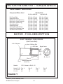
PUMP
MOTOR
BOOM
Service Manual
P/N 02969480
(Apr. 2004)
Alamo Industrial
1502 E. Walnut
Seguin, Texas 78155
830-372-1480
2004 Edition
©
2004 Alamo Group Inc.
INTRODUCTION
ABOUT THIS MANUAL:
The intent of this publications to provide the competent technician with the information
necessary to perform the CORRECT repairs to the Alamo Industrial Product. This will, in turn provide
for complete customer satisfaction
It is hoped that the information contained in this and other Manuals will provide enough detail to
eliminate the need for contact of the Alamo Industrial Technical Service Dept. However, it should be
understood that many instances may arrive wherein correspondence with the Manufacturer is
necessary.
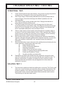
CONTACTING MANUFACTURER: (Please help us Help You! Before You Call! )
Alamo Industrial Service Staff Members are dedicated to helping you solve yours or your
customer’s service problem as quickly and efficiently as possible. Unfortunately, we receive entirely
to many calls with only a minimum amount of information. In some cases, the correspondent has never
gone out to look at the equipment and merely calls inquiring of the problems described to him by the
operator or customer.
Most calls received by Alamo Industrial Service can be classified into approx. 6 general categories.
1.
Hydraulic or Mechanical Trouble Shooting.
2.
Request for Technical Information or Specifications.
3.
Mounting or Fitting Problem.
4.
Special Service Problem.
5.
Equipment Application Problems.
6.
Tractor Problem Inquiries.
HOW YOU CAN HELP:
Make sure the call is necessary! Most of the calls received may not be necessary if the Dealer
Service Technician would do the following.
1.
Check the Service Information at your Dealership provided by Alamo Industrial, This
would include, Service Bulletins, Information Bulletins, Parts Manuals, Operators Manuals or
Service Manuals, many of these are available via the Alamo Industrial Internet site (Alamo - Industrial.
Com). Attempt to diagnose or repair problem before calling.
2.
If a call to Alamo Industrial is needed, Certain Information should be available and ready
for the Alamo Industrial Service Staff. Such information as, Machine Model, Serial Number, Your Dealer
Name, Your Account Number and Any other information that will be useful. This information is vital for
the development of a prompt and correct solution to the problem. This will also help to develop a
database of problems and related solutions, which will expedite a solution to future problems of a similar
nature.
3.
The technician may be asked to provide detailed information about the problem
including the results of any required trouble shooting techniques. If the information is not available, The
technician may be asked to get the information and call back. Most recommendations for repairs will
be based on the procedures listed in the Service Manual / Trouble Shooting Guide.
CONTACT ALAMO INDUSTRIAL:
Alamo Industrial, 1502 E. Walnut St. Seguin TX. 78155, Technical Service Dept. PH: 830-372-2708
Machete (Service Manual) 04/04
© 2004 Alamo Group Inc.
3
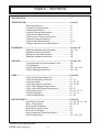
INDEX - REPAIRS
Page
INTRODUCTION........................................................................................ 3
SPECIFICATION.........................................................................................
Boom Specifications.....................................................
Cutting Circuit Specifications.........................................
Filtration Specifications..................................................
Hydraulic Cylinder Specifications...................................
Hydraulic Hose Specifications........................................
Hydraulic Hose Torque Specifications...........................
Hydraulic Pump Specifications......................................
Hydraulic Valve Specifications.......................................
General / Speceial Torque Specifications.....................
10 thru 13
10
10
10
11
12
14
11
12 -13
14
BLADE BAR................................................................................................
Blade Bar Assemble & Dis-Assemble..........................
Blade Bar Torque Specification.....................................
Blade Bolt Torque Specifications...................................
Blade Bar Installation Instructions..................................
121 thru 128
138 - 142
138
138
142
KING PIN.....................................................................................................
Tools Required List (Recommended Tools)................
Tool Description.............................................................
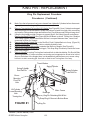
King Pin Removal Procedure.........................................
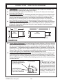
King Pin Bushing Replacement......................................
132 thru 135
132
134
132 - 133 - 134
134 - 135
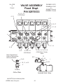
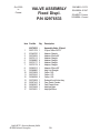
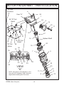
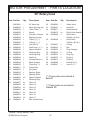
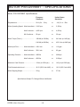
PUMP...........................................................................................................
Pump Charge Pump Adapter Asy..................................
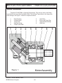
Pump Dis-Assembly Instructions...................................
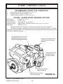
Pump Introduction...........................................................
Pump Manual Servo Control Asy....................................
Pump - Motor Engage Requirements.............................
Pump - Motor Dis-Engage Requirements......................
Pump Parts Location......................................................
Pump Re-Assembly.......................................................
Pump Rotaiting Kit Asy...................................................
61 thru 82
77
72 - 73
61 - 62 - 63
78 - 79 - 80
66
66 - 67
68 - 69 - 70 - 71
74 - 75 - 76
81 - 82
MOTOR CIRCUIT........................................................................................ 83 thru 94
Motor Electrical Control.................................................. 84 - 85 - 86 - 87 - 88
Motor - Pump Actions.................................................... 89 - 90 - 91
Motor System Schematic.............................................. 92
Motor Shuttle Valve Location.......................................... 93
Motor Service & Repair.................................................. 94
Motor Component Torque Specification........................ 111
Motor Dis-Assembly....................................................... 101 - 102 - 103
Machete (Service Manual) 04/04
© 2004 Alamo Group Inc.
4
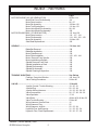
INDEX - REPAIRS
MOTORP/N 02967193 ( 60" HEAD MOTOR).............................................
Motor End Cover Dis-Assembly....................................
Motor Parts Location......................................................
Motor Re-Assembly........................................................
Motor Tool Descriptions.................................................
Motor Valve Block Dis-Assembly...................................
Motor Valve Block Re-Assembly....................................
MOTOR P/N 02979881 ( 50" HEAD MOTOR).............................................
Motor Parts Location.......................................................
Motor Dis-Assembly.......................................................
Motor Re-Assembly........................................................
Shaft Seal Replacement................................................
Page
95 thru 114
101
96 - 97
105 thru 110
111 thru 113
98 - 99
100
115 thru 130
116 - 117 - 118
119 - 120 - 122 - 123
124 thru 129
129
SPINDLE...................................................................................................... 138 thru 144
Blade Bar Removal......................................................... 138
Blade Bar Installation....................................................... 142
Motor Plate Removal....................................................... 139
Motor Plate Installation..................................................... 142 - 143 - 144
Motor Removal From Spindle......................................... 139
Motor Installation on Spindle............................................ 142
Spindle Removal From Deck.......................................... 139
Spindle Installation on Deck............................................ 142
Spindle Dis-Assembly.................................................... 140
Spindle Re-Assembly..................................................... 141
Spindle Cleaning & Inspection........................................ 139
TROUBLE SHOOTING.............................................................................. See Below
Problem, Cause And Solution........................................ 145 thru 178
Valve Testing Procedures.............................................. 54 thru 60
VALVE..........................................................................................................
Joystick Control / Trouble Shooting................................
Joystick Plug...................................................................
Joystick Wirineg Harness...............................................
Valve Components.........................................................
Valve Operation..............................................................
Valve Parts.....................................................................
Valve Trouble Shooting..................................................
Wiring Harness, General View.......................................
Wiring Harness, Plug.....................................................
Wiring Harness, Joystick...............................................
Hydraulic Flow, load Sensing.........................................
Hydraulic Flow, Fixed Displacement..............................
Machete (Service Manual) 04/04
© 2004 Alamo Group Inc.
5
15 thru 60
19 - 20 - 21
22 - 23 - 24
19 - 22 - 23 - 24 - 25
26 - 27 - 28 - 29 - 30
17-18
40 thru 45 & 46 thru 52
53 thru 60
16
25
22 - 23 - 24
31 - 32 - 33 - 34
35 - 36 - 37 - 38
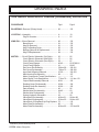
DRAWING INDEX
THIS INDEX INDICATES FIGURE (DRAWING) LOCATION
PROCEDURE
Fig.#
Pge.#
BLADE BAR...Removal (Rotary Head)............................... 85................. 122
JOYSTICK.....Assembly...................................................... 4................... 19
Plug Pin Location.......................................... 6.................. 22
KING PIN.......Boom Removal.............................................
Boom Mount..................................................
King Pin Removal.........................................
King Pin Bushing Driver................................
Bushing Removal & Replacement...............
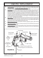
King Pin Replacement..................................
80................
81.................
81.................
82.................
83.................
84.................
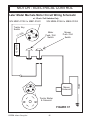
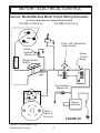
MOTOR.........Circuit Electric Schematic (Old Style)..........
Circuit Electric Schematic (Mid Style)..........
Circuit Electric Schematic (New Style)........
Circuit Pump Engage...................................
Circuit Pump Engage...................................
End Cover Dis-Assembly.............................
End Cover Re-Assembly..............................
Input Seal & Bearing Removal......................
Main Housing Re-Assembly..........................
Motor Components Torque Specifications...
Motor Repair Tools Descriptions..................
Output Shaft Assembly Removal.................
Rotating Group Dis-Assembly......................
Rotating Group Re-Assembly.......................
Parts Location...............................................
Shuttle Valve Dis-Assembly..........................
Shuttle Valve Re-Assembly..........................
System Hydraulic Schematic.......................
Valve Block Dis-Assembly............................
Valve Block Re-Assembly............................
Valve Block O-Ring/Back-Up Ring Replace.
Motor Plate Dis-Assembly............................
Motor Plate Re-Assembly.............................
36................. 85
37................. 86
38................. 87
40-42............ 65-67-89-91
41................. 66-90
56 thru 58..... 100-101
70 thru 73...... 108-109
47-59............ 102-103
69................. 107
------ ............. 111
77 thru 79..... 111 thru 113
60-61............ 103
63-64............ 104
65-66............ 105
46................. 96
44-45.............. 93
75................... 110
43................... 92
48 thru 51...... 98 thru 99
52 thru 55...... 99 thru 100
76................... 110
86................... 123
89 thru 95...... 127 thru128
Machete (Service Manual) 04/04
© 2004 Alamo Group Inc.
6
132
133
133
134
134
135
DRAWING INDEX
PROCEDURE
Fig.#
PUMP.............Electric Control.............................................
Circuit Motor Engaged..................................
Circuit Motor Disengaged.............................
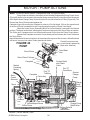
Charge Pump Adapter Assembly.................
Dis-Assembly................................................
Re-Assembly................................................
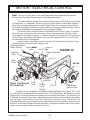
Parts Location...............................................
Port Locations...............................................
Rotating Kit Parts Location...........................
Pump / Motor Port Connections...................
39................... 88
40-42.............. 65-67-89-91
41................... 66 and 90
30-31.............. 77
27-28.............. 72 thru 73
29.................. 74
25-26.............. 68 thru 70
24................... 63
34................... 82
39................... 64
SERVO CNTRL.Control System.........................................
Control Assembly (Manual Type - Old Style)...
Control Assembly (Manifold Type - New Style).
Control Electric Control................................
40................... 65
32................... 79
33................... 80
39................... 88
SPINDLE....... Blade Bar Removal (Rotary Head)...............
Blade Bar Replace (Rotary Head)................
Motor Plate Removal (Rotary Head).............
Motor Removal (Rotary Head).......................
Spindle Dis-Mount from Deck (Rotary Head)
Spindle Dis-Assembly...................................
Spindle Re-Assembly...................................
Spindle Re-Mount to Deck............................
Motor Plate Installation..................................
85................... 138
85................... 138
86................... 139
86................... 139
86................... 139
87.................. 140
88.................. 141
89 thru 95....... 143 thru144
89 thru 95....... 143 thru144
VALVE, 5 SPLSpecific Section Operation...........................
Components.................................................
Hydraulic LocK Valve....................................
Operation......................................................
Part Numbers...............................................
Testing.........................................................
Type.............................................................
2.................... 17
11 thru 14....... 27 thru 30
3.................... 18
15 thru 18....... 32 thru 38
-----................ 40 thru 51
19 thru 23....... 56 thru 60
10.................. 26
WIRING SYS. Harness Schematic, Joystick End..............
Harness Schematic, Vlave End..................
Harness Valve Plug (Old Style)...................
Harness Valve Plug (Old & New Style).......
Control Valve Wiring....................................
Plug Pin Location........................................
7-8.................
9....................
5....................
35..................
1....................
6....................
Machete (Service Manual) 04/04
© 2004 Alamo Group Inc.
7
Pge.#
23 thru 24
25
22
84
16
22
Machete (Service Manual) 04/04
© 2004 Alamo Group Inc.
8
Specifications Section
Machete (Service Manual) 04/04
© 2004 Alamo Group Inc.
9
SPECIFICATIONS - MACHETE
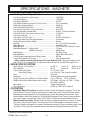
1. Cutting Circuit Specifications
Hyd. Pump Speed (Front Aux Pump)...................................... 1950 RPM
Hyd. Motor Speed.................................................................. 1220 RPM
Hyd. Motor Rated HP............................................................. 199 HP
Hyd. Motor Rotation (as viewed f/ Top of the Deck)................... CW (Clockwise)
Relief Valve Setting At Motor................................................. 4000 PSI
Relief Valve Setting At Pump................................................ 4500 PSI
Hyd. Pump Flow (Front Pump @ 1950 RPM).......................... 25.3 GPM
Hyd. Oil Operating Temperature.......................................... 95 Deg, (F) Above Ambient
Hyd. Oil Filtration, (Discharge f/ Charge Pump)......................... 10 Micron
Hyd. Tank Capacity............................................................... 17 Gal.
Hyd. Motor Circuit Oil Type *................................................ ISO AW 100 Hyd Oil
Hyd. Motor Start Stop Time (Approximate)........................... 6 Seconds
Cutting Diameter, (Rotary Head).......................................... 58 Inch
Spindle................................................................................... 4.5 “ by 9” Heat Treated Alloy
Blade Bar Type...................................................................... Stacked 3 Leaf
Blade Bar Size....................................................................... 1-1/4” Thick X 5" Wide (Ea. Leaf)
Blade Bar Material.... Bottom Leaf....................................... T1 Steel
Middle & Top Leaf............................. HRFB Steel
Blade Swing........................................................................... 360 Deg Swing
Blade Material........................................................................ High Carbon Alloy Steel
Cutter Weight. (Approximate w/ Rotary Head)..................... 950 lbs.
Cutter Deck Opening & Closing........................................... Hyd. Operated Door
* Older models recommended Universal Tractor Hydraulic Oil, This was changed to ISO
AW 100 Hyd. Oil, If changing Oil in Older units switch to New Oil, DO NOT Mix types of Oil.
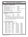
2. BOOM SPECIFICATIONS
Boom Reach 21 Foot Boom...............................
24 Foot Boom.......................................................
Frame (Old Low Frame).......................................
(New High Frame).....................................
Pins.......................................................................
Bushings...............................................................
Weight (vary w/ size of Boom not include Head)..
Weight, Head Only (Add to Boom when used).....
Boom Rest............................................................
Boom Mounting.....................................................
Up 20'-3"
Out 21'-4"
Down 12'-11"
Up 23'
Out 24'-2"
Down 14'-5"
4" X 6" Rect, Tube
4 X 4 Sq. Sq. Tube (formed corners)
Chromed
Self Lubricating (No grease needed)
21 ft = 2250 lbs. 24 ft = 2300 lbs.
60" Rotary = 950 lbs., 48" Flail = 770 lbs.,
FML100H = 990 lbs.
Tractor Axle Mounted
ROPS or CAB Tractor Optional
3. FILTRATION
Control Valve Functions: Control functions include All Hydraulic Cylinders, These are
powered by the Tractor Hydraulic System and are protected by the Tractors Filtration system.
Maintenance and specification of this should be per Tractor Manufacturer instructions. Later
Models Had an Inline Filter assembly (P/N 02976066) added to Filter Tractor System between
Valve and Tractor. Change Filter every 200 to 250 hrs. Operation recommended maximum.
Mower Head Functions: Mower Head Functions are operated by Pump, which is mounted
to the front of the Tractor Engine. This will have an inline Filter installed into hydraulic circuit,
This filter should be changed on a regular maintenance schedule. Filter are rated by Micron size
(10 Micron), Filter should be replaced with the same Micron and High Pressure rated Filter.
Machete (Service Manual) 04/04
© 2004 Alamo Group Inc.
10
SPECIFICATIONS - MACHETE
4. HYDRAULIC PUMP CIRCUIT
Pump Type..........................................................................
Pump Speed (Front Engine Mounted).................................
Relief Setting at the Pump...................................................
Pump Flow (Front Engine Mounted @ 1950 RPM).............
Oil Operating Temperature..................................................
Filter, Discharge from Charge Pump..................................
Hydraulic Tank Capacity......................................................
Hydraulic Oil Type (Pump & Motor Circuit)..........................
Motor Start / Stop Time (Approximate)................................
Piston Type
1950 RPM
4500 PSI
25.3 GPM
100 deg. (F) above Ambient Temp
10 Micron
17 Gallons
ISO AW 100 HYD OIL
6 Seconds
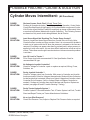
5. HYDRAULIC CYLINDERS SPECIFICATIONS
Hydraulic Cylinder Drift Rates:
Cylinder Function
Travel
Time
Lift ............................................. 1" Travel................... 8.0 minutes
Dipper........................................ 1" Travel................... 7.1 minutes
Tilt (w/hyd. lock closed)............. 1" Travel................... No Drift
Tilt (w/hyd. lock open)................ 1" Travel................... 5.8 minutes
Measured Cylinder Drift Rates are measured as the amount of time required for the rod
to move 1", The times shown represent the nominal times for a new machine. The
times should be expected to decrease somewhat over time. Drift rates exceeding the
times given (meaning that it takes LESS time for the Rod to move 1") may indicate a
leakage problem in the Cylinder, Lines or Valves.
Hydraulic Cylinder Pressure Rates:
See Valve Spool Functions & Specs for Rates.
Hydraulic Cylinder Repair Specs:
Cylinder
Cylinder
Piston Nut
Gland
Seal Kit
Part No.
Function
Torque ft. lbs.
Torque ft. lbs.
Part No.
02967172
02967172A
02967173
02967173A
02967174
02967174A
02967175
02967175A
02961480
02961480A
02970710
02970710A
02971423
02811000
02811000A
Swing (21' & 24')
Swing (21' & 24')
Lift (21' & 24')
Lift (21' & 24')
Dipper (21' & 24')
Dipper (21' & 24')
Tilt (21' & 24')
Tilt (21' & 24')
Door (Rotary)
Door (Rotary)
Door (Flail Axe)
Door (Flail Axe)
Slide (Timber Cat)
Door (Ditcher)
Door (Ditcher)
400-500
400-500
400-500
400-500
400-500
400-500
400-500
400-500
150-250
150-250
40-60
40-60
400-500
150-250
150-250
135-149 (Cap)
80-120 (Head)
135-149 (Cap)
80-120 (Head)
135-149 (Cap)
80-120 (Head)
135-149 (Cap)
80-120 (Head)
100-120 (cap)
80-120 (Head)
None (Lockwire)
80-120 (Head)
50-60 (Tie Rod)
None (Lockwire)
80-120 (Head)
02968612
02975530
02968610
02975527
02968610
02975527
02968612
02975530
02972147
02975528
02972762
02975532
02973505
02840600
02975528
Continued Next Page
Machete (Service Manual) 04/04
© 2004 Alamo Group Inc.
11
SPECIFICATIONS - MACHETE
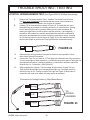
6. HYDRAULIC HOSE CODES
Hydraulic Hose Band Mark Color Codes:
Hose's and/or fittings are marked with a Color Coded Plastic Band around it. Some Bands
are a solid Color and some have a Colored Stripe. DO NOT remove these bands unless you
replace them. All Bands with Solid Colors connect to Rod End of Cylinder. All Bands with
Stripes connects to Butt End of Hydraulic Cylinder (or connections leading to them).
AlwaysCheck Hose Size & Color Code
Color
Tie
Color Tie
Abbreviation
Hose
Size
Hydraulic
Connection
Orange
Orange
Orange / White Stripe
Green
Green / White Stripe
Blue
Blue
Blue / White Stripe
Red
Red
Red / White Stripe
Yellow
Yellow / White Stripe
OR
OR
OR / W
G
G/W
B
B
B/W
R
R
R/W
Y
Y/W
Medium
Large
Medium
Medium
Medium
Medium
Large
Medium
Medium
Large
Medium
Small
Small
Lift Cylinder, Rod End
Return Flow from Motor
Lift Cylinder, Butt End
Swing Cylinder, Rod End
Swing Cylinder, Butt End
Dipper Cylinder, Rod End
Case Drain for Motor
Dipper Cylinder, Butt End
Tilt Cylinder, Rod End
Pressure Flow to Motor
Tilt Cylinder, Butt End
Door Cylinder, Rod End
Door Cylinder, Butt End
7. VALVE SPECIFICATIONS
Valve Type:
Electrically controlled, Pilot Operated, 5 Spool, Proportional Control Valve, Available as
Closed Center Load Sense (CCLS) or Open Center Fixed Displacement (OCFD) Option
depending on Requirements of Tractor Model / Series
Valve Construction:
Individual Spool with Tie Rod Bolt together type.
Valve Controller:
Electrical Joystick, Reaction Time = 300 Milliseconds, Voltage Rated = 12 Volt with a 11 to 15
Volt Range.
Valve Port Markings:
Ports Marked with letter "A" (solid marking hose bands) are for Functions Connected to Rod
End of Cylinders. Ports Marked with letter "B" (Striped marking hose band) are for Functions
Connect to Butt End of Cylinders. (See Decal # 02969106 Hydraulic Hose Hook-Up on Next
Page).
Continued Next Page
Machete (Service Manual) 04/04
© 2004 Alamo Group Inc.
12
SPECIFICATIONS - MACHETE
Note: Old style Valve (Apitech 10 Plug Wire Harness type) is not shown
Below, this is the later style 5 Plug Harness type.
Yel / Wht Red / Wht Blue / Wht Org / Wht
Grn / Wht
Pressure
Supply
"A"
"A"
"A"
"A"
"A"
Door
Tilt
Dipper
Lift
Swing
"B"
"B"
"B"
"B"
"B"
Return
Yellow
Red
Blue
Orange
Green
Tank
Solenoid Side Of Valve
8.
Valve Restrictors:
The Restrictors Vary in size from Spool to Spool, Some Ports do not use restrictors at all,
See parts page for types and sizes. Restrictors operate by controlling the rate of flow to or
from a Cylinder, This is most commonly done by the size of the Hole the Oil is sent through,
But can be done by Hose Size. There are also 1 way and 2 way restrictors, Check Parts
pages. DO NOT Remove, Change or Modify Restrictors.
Valve Spool Funtions & Specs:
Port
Marked
"A"
"B"
"A"
"B"
"A"
"B"
"A"
"B"
"A"
"B"
Spool
Cyl.
No. Function
1
Swing
1
Swing
2
Lift
2
Lift
3
Dipper
3
Dipper
4
Tilt
4
Tilt
5
Door
5
Door
Cyl.
Travel
Forward
Back
Down
Up
Out
In
Up
Down
Open
Close
Flow
GPM
2.3
3.5
4.5
6.5
4.0
5.5
4.0
4.0
2.5
2.5
Pressure
Rating
2000 psi.
2000 psi.
1000 psi.
2000 psi.
2300 psi.
1000 psi.
System
System
System
System
Restrictor
Size
0.040"
0.050"
--------0.070"
0.063"
---------0.050"
Lock Valve
-------------------
Cycle
Time
8.5 Seconds
9.0 Seconds
12 Seconds
11 Seconds
10 Seconds
10 Seconds
6.0 Seconds
8.0 Seconds
5.0 Seconds
6.0 Seconds
Valve Spool Functions & Specs:
In the Chart Cycle Times listed above are close approximations of actual times based on
machine testing, Times indicate the time for the Cylinder to travel the full amount of its extension or
retraction. The lift times up and down are taken with the dipper fully extended and begin with the Deck
flat on the ground. All Cycle times are measured at the rated Tractor RPM. Test Times should be close
to above but can vary some from unit to unit; Times listed are a guide to show approx. what Cycle
times for tour Unit should be.
Valve Leakage: Maximum internal Valve Leakage from the Cylinder. Ports to Tank at any Valve
Segment, Oil Pressure at 1450 PSI and Oil Viscosity at 102 SSU = 1.25 Cubic Inch / Minute
Standby (Pilot) Pressure:
Standby (Pilot) Pressure = 200 to 250 PSI.
Continued Next Page
Machete (Service Manual) 04/04
© 2004 Alamo Group Inc.
13
SPECIFICATIONS - MACHETE
9.
HOSE END FITTING TORQUE SPECS:
Hose End Type: 37 Degree Angle End Steel Hose End Fittings*
Dash
Nominal Cyl.
Torque
Torque
Size
Size (in.)
in. lbs.
ft .lbs.
-4
1/4"
140
12
-6
3/8"
230
19
-8
1/2"
450
38
-10
5/8"
650
54
-12
3/4"
900
75
-16
1"
1200
100
-20
1-1/4"
1600
133
-24
1-1/2"
2000
167
-32
2"
2800
233
* Straight Threads do not always seal better when higher torques are used. Too much torque
causes distortion and may lead to leakage. DO NOT over torque fittings and DO NOT allow any
contaminants to enter system through fittings when installing them.
10. Special Torque Specifications (Rotary Heads)
Motor to Spindle Housing.........................................................
Spindle to Deck........................................................................
Spindle to Adjusting Nut (Bearing Preload)..............................
Blade Bar Leaf Bolts Old Style 7/8" Bolts...............................
New Style 1-1/4" Bolts...........................
Blade Bar to Spindle Bolts.........................................................
Blade Bolts.................................................................................
Motor Plate.................................................................................
100 ft. lbs.
425 ft. lbs.
25 in. lbs. Rolling Torque
600 ft. lbs.
2000 ft. lbs.
400 ft. lbs.
400 ft. lbs.
See Set Up Instructions
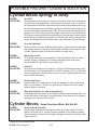
11. TORQUE VALUES - BOLTS: Recommended Torque, Ft. lbs.
& (Nm)
IMPORTANT! Listed below IS BOLT TORQUE and NOT APPLICATION TORQUE, Component
Application Torque will vary depending on what is bolted down and the type material (Metal) that is being
bolted together. Thread condition and lubrication will vary Torque settings.
Inche Sizes
Bolt
Dia.
inch
1/4
5/16
3/8
7/16
1/2
9/16
5/8
3/4
7/8
1
1-1/8
1-1/4
2 (B)
Metric Sizes
5 (D)
8 (F)
Plain Head 3 Dashes 6 Dashes
Not Used
Not Used
Not Used
35 (47)
55 (75)
75 (102)
105 (142)
185 (251)
160 (217)
250 (339)
330 (447)
480 (651)
10 (14)
20 (27)
35 (47)
55 (75)
85 (115)
130 (176)
170 (230)
300 (407)
445 (603)
670 (908)
910 (1234)
1250 (1695)
14 (19)
30 (41)
50 (68)
80 (108)
120 (163)
175 (230)
240 (325)
425 (576)
685 (929)
1030 (1396)
1460 (1979)
2060 (2793)
ALWAYS
CHECK
MARKINGS
ON
TOP
OF
BOLT
HEAD
OR
OTHER
BOLT
DESCRIPTIONS
Machete (Service Manual) 04/04
© 2004 Alamo Group Inc.
14
Bolt
Dia.
mm
6
8
10
12
14
16
18
20
22
24
27
30
33
36
4.8
5
11
20
37
60
92
118
160
215
285
450
600
800
900
8.8
7
20
40
70
100
155
216
270
330
500
875
1200
1600
2100
10.8
12
25
58
105
140
200
280
355
430
700
1000
1700
2300
3000
VALVE SECTION
MACHETE (Service Manual) 04/04
© 2004 Alamo Group Inc.
15
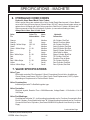
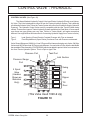
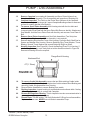
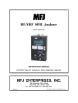
CONTROL VALVE - WIRING
(Used 1998 & Up)
Pressure Port
Tank Port
Inlet Section
P
T
A
5 Spool Valve
(Handles Shown
as Illistration Only)
B
Swing
A
B
Lift
A
B
Dipper
A
B
Tilt
B
Door
A
Ground
(Black)
Starter Solenoid
(Brown)
Solenoid Lock
Valve
H
R
Voltage Supply
(Red)
Junction Box
(Joystick)
Clamp
1
2
Pump Solenoid Connector
3
4
5
1 : Swing
2 : Lift
3 : Dipper
4 : Tilt
5 : Door
FIGURE 1
MACHETE (Service Manual) 04/04
© 2004 Alamo Group Inc.
16
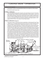
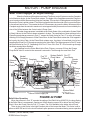
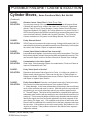
CONTROL VALVE - OPERATION
HYDRAULIC FUNCTIONS:
The Hydraulic Functions of the Machete Boom Mower are controlled by a Pilot operated
Electrically Actuated Control Valve.
GENERAL OPERATION:
This Section addresses the method of operation of the electrical part of controls. The function
of the Hydraulic Valve itself will be covered in another Section. Three Functions, The Lift, The
Dipper and the Swing are "Proportional" meaning that the Speed of operation can be slowed
down or Sped up according to the position of the Joystick Control. The Door and Tilt Functions
are "On" or "Off" only, Meaning that their speed of operation is dependent upon the volume
of Oil Flowing through the Circuit and cannot be controlled by the Joystick position. In Our
application the Oil Volume varies with the Tractor Engine Speed.
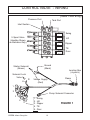
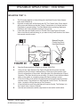
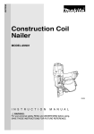
SPECIFIC OPERATION: (Figure 2)
The Electrical Power to operate the Circuits is obtained from a Switched and Fused Tractor
Voltage Source. This means that the Electrical Power Wire to the Joystick Controller should
only be connected to a Wire that has Voltage when the ignition is in the "On" Position. If
Connection of the Joystick Controller is to a constant current source it will cause power drain
on Battery and eventually Battery Failure. Furthermore the Master Switch on the Joystick
Console (Figure 5) must be in the "On" position to allow for the operation of any of the Control
Functions. To achieve Electrical Proportional Actuation, The main Spool Position is adjusted
so that it corresponds to an Electrical signal sent from the Joystick Controller. The Position
of the Joystick is Electrically sensed by a Coil and Magnet located in the Joystick Assembly
which sends the positioning information to the electric controller in the Valve. The Signal from
the Joystick is converted by the electronic Controller into Hydraulic Pressure by activating a
series of Hydraulic Valves. These Valves direct the Standby or Pilot Pressure Oil to the proper
end of the Spool to cause it to move. Likewise the position of the Spool is converted in the Spool
position transducer to feedback signal. This Signal is registered by the electronic controller
which will activate the series of valves as needed to move the spool in either direction until the
spool is positioned in accordance with the location of the Joystick. An equilibrium between the
Joystick and feedback signal is the end result.
Electric
Controller
Electric Signal for Joystick Controller
Pilot Pressure
Control Valve
B
A
Segment
Handle is shown
for Illustration
Only
FIGURE 2
Spool Positioning Valves
MACHETE (Service Manual) 04/04
© 2004 Alamo Group Inc.
Spool Position Transducer
17
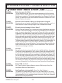
CONTROL VALVE - OPERATION
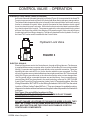
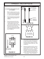
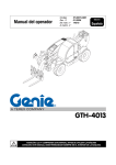
HYDRAULIC LOCK VALVE: (Head Tilt Function)
An Electric Solenoid Operated Hydraulic Lock Valve (Figure 3) is incorporated in the Head Tilt
Function to prevent excessive (Head Lift Cylinder) leak down during storage or transportation.
The Solenoid which operates this valve is normally in the Locked position until Head Lowering
function is actuated at Joystick. When Joystick is actuated to lower Head an electric signal
is sent to solenoid to open Lock valve. When the function to raise the Head is activated there
is no electric signal from Joystick. The pressure against the valve when head is being raised
will force Valve open like a relief Valve allowing Oil to pass through it. If this valve will not open
it could stop head from lifting or dropping. The valve is plumbed into the Hydraulic Circuitry of
the Head Tilt Function and is located near the Control Valve.
Hydraulic Lock Valve
FIGURE 3
ELECTRIC SIGNALS:
Electrical Signals are sent to the Controllers etc. through a Wiring Harness, The Harness
is supplied with a one way connector at the Joystick Console Box (So it can not be installed
Wrong). Connectors are supplied for each electric valve controller connection, These are
labeled (with Letter code A,B,C etc.) for the function which they are connected. The Plug
will only fit together one way and should always have right connections. BUT if the terminals
within this Plug are moved around or the connections at the valve end are changed then
the Plug would still be connected the same way and be Wrong. If any connections are
removed they MUST be placed back in the same order they came out of. (SEE FIGURE
5 and 6) See Figure 6 for Plug Connection (Letter Code) & Terminal locations, Also the
Wiring Schematic, BUT NOTE on the Wiring Schematic it WILL NOT be the actual
location of Wires (Letter Codes ABC etc.), They are changed to enable the wiring
diagram to be drawn with as few lines crossing each other as possible for illustration
purposes.
See Figure 6 for actual Wire locations in Plug.
DO NOT USE WIRE SCHEMATIC PIN LOCATION IN PLUG TO MAKE
CONECTIONS IN ACTUAL PLUG.
DO NOT CHANGE LOCATIONS OF PINS AND/OR WIRES IN PLUGS, THEY
MUST BE CONNECTEDTHE SAME WHEN REPLACED OR THE SYSTEM
WILL MALFUNCTION AND THIS COULD ALSO DAMAGE JOYSTICK
CONTROLLER COMPONENTS.
MACHETE (Service Manual) 04/04
© 2004 Alamo Group Inc.
18
CONTROL VALVE - JOYSTICK
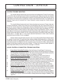
JOYSTICK FUNCTIONS: (Figure 4)
To operate a function the following series of events must work.
1.
2.
3.
4.
5.
6.
7.
The Joystick Controller is moved in the correct direction the required distance, During its
movement an electrical signal is sent to the electric Controller in the proper Valve Section
of the Control Valve.
The Electric Controller sends an electrical signal, which causes the Proportional Control
Valves to actuate the proper amount based on the signal from the Controller. EXAMPLE:
Valves 1 & 3 allow Pilot Pressure Oil to flow to the corresponding end of the Spool, Thus
causing it to move. Valves 2 & 4 allow the Oil from the opposite end of the Spool to return
to the Tank. (NOTE: Lift, Swing and Dipper functions are Proportional, Door and Tilt
functions are “ON” or “Off” Only, See later section for explanation of Proportional).
The Spool position Transducer sends an electrical signal to the Electronic Controller which
indicates the position of the Spool.
The Electronic Controller will continue to adjust the Valves (1 - 4) in order to maintain an
equilibrium between the Joystick signal and the feedback signal.
Reaction time from the time the Joystick is moved until the Spool moves is approximately
300 milliseconds.
The Rocker Type Switch on top of the Joystick is spring centered 3-function switch (Figure
4). When used alone the Rocker Switch controls the Head Tilt function, When used in
conjunction with the Trigger Switch the Rocker Switch opens and closes the Door, Both
of these functions are NOT controlled Proportionally. When the Toggle Switch is activated,
The electrical signal fully opens either Valve 1 or 3 and fully closes either valve 2 or 4 in the
correct Valve Section depending on which way the Spool needs to travel. The Electronic
Controller and the Spool position Transducer are not included in these functions.
Earlier Model Joysticks Master Switch was a 2 Push/Pull Switch type. Later Models have
one Push/Pull Switch with a Momentary Pull Start Switch built in to it and a Lighted Rocker
Master Switch.
Trigger
Switch
Pistol Grip
Handle Switch
Fuse
Rocker
Switch
Rocker Switch Only
Motor Start
Stop Switch
Master
Switch
© 2004 Alamo Group Inc.
Push Right
Push Left
=
=
Tilt Down
Tilt Up
Rocker & Trigger Switch
Push Right
Push Left
=
=
Door Close
Door Open
Pistol Grip Handle Switch
Push Front
Pull Back
Push Right
Push Left
Rotate Right
Rotate Left
FIGURE 4
MACHETE (Service Manual) 04/04
Joystick Functions
19
=
=
=
=
=
=
Lift Down
Lift Up
Dipper Up
Dipper Down
Swing Out
Swing In
CONTROL VALVE - JOYSTICK
JOYSTICK TROUBLE SHOOTING:
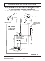
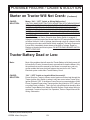
The Joystick Wiring Harness has 2 wire connections to link Machete to Tractor Power Supply
(12 Volt DC). One red colored wire (for Positive Connection) and 1 Black colored wire (for Ground
Connection). These wires will provide power to start the Front Auxilary Pump that runs the Cutting
Head Motor Circuit and power to operate the 5 spool Valve Electrical Circuits. The Hydraulics to
operate 5 Spool valve is furnished from Tractor Hydraulic System through the Tractors Internal
Hydraulics.
The Joystick Wiring Harness also has 2 other wires that must connect to Tractor; these are
2 Brown colored wires. These wires connect in to form the Safety Link in the Tractor Start Circuit to
prevent the Tractor Engine from being started when the Machete Electrical Circuit is energized.
These wires (Brown Colored) connect the Starter relay Circuit of the Tractor to the Master “On” / “Off”
Switch (Rocker Switch on later models) on the Joystick Console of the Machete. Caution: These 2
wires (Brown Colored) are to be spliced into Tractor Starter Relay Wire (approximately 3 “) behind
Starter Switch (normally Key Switch). DO NOT splice wires (Brown Colored) any further from Starter
Switch than 3”, if further than 3" it may cause electrical interference in other tractor electrical
operations when the Motor Circuit is engaged.
With the Switch (Keyed Switch) of tractor in the “On” position and the Rocker Master Switch
on Joystick Console in the “On” position a Green Light (on Master Switch) should be on. (Note: Early
models did not have a Lighted Master Switch only a Push / Pull Switch). This green light indicates
that electrical power is available to the five movement control circuits of the Valve, and to the start
system of front pump as well as start circuit of Motor. To Check this Current at Switch (Master or
Motor Stop Start Switch) it can be done with a test light or Voltmeter.
VALVE CONTROLS CONNECTION TROUBLE SHOOTING:
1.
2.
3.
4.
5.
6.
7.
8.
9.
Proportional Controlled Functions, Only the Swing, Lift and Dipper Functions are
Proportional Controlled, Therefore only these three functions will show progressive readings.
The Tilt and Door Functions are “On” or “Off, when checking keep track of which connection
is being check, as it will make a difference in reading on voltmeter
All Connections are marked on plug where they plug onto Valve (See Figure 5)
Make sure Tractor Engine is off and cannot be started while you are working on it.
Relieve Any Hydraulic Pressure, Make sure any Hydraulic Pressure in any Lines or
Cylinders has been relieved and Mower / Boom are resting on the Ground completely. This
should be done by working the Manual Overrides on Valve to be sure pressures are relieved.
Turn on Ignition Switch of Tractor to the “On” position (But DO NOT Start Engine)
Switch on the Master Rocker Switch (Push / Pull on older models) to the “On” position.
Remove the “Din” connector from the control Valve Section being tested to check voltage.
The Spade type Pins will be on the Section of the Valve and the plug will have slots where it
plugs on, Each of these connectors have numbers at the slot to ID which connections (see
Figure 5) connect where, these plugs cannot be reversed, will only plug on one way.
Voltage from the No. 1 Slot, Positive (12 Volt DC), Voltage will depend on Battery condition,
it cannot exceed the amount of the voltage in the battery and should not be less than Battery
Voltage when Joystick Switch is activated, So always Know what voltage is in Battery. (See
Figure 5)
MACHETE (Service Manual) 04/04
© 2004 Alamo Group Inc.
20
CONTROL VALVE - JOYSTICK
JOYSTICK TROUBLE SHOOTING:
VALVE CONTROLS CONNECTION TROUBLE SHOOTING: (Continued)
10.
11.
12.
13.
Voltage from the NO. 2 Slot, Positive (12 Volt DC) Voltage should be 1/2 of what reading
at Slot No. 1 is. With Voltmeter connected to the No. 2 Slot of Plug and the Joystick in Neutral
(Centered) position begins moving Joystick and watch Voltmeter, (be sure you are moving
Joystick to Match functions being checked). The Voltage should rise as Proportional to the
movement of Joystick (Proportional Sections Only) and “on” or “off” on sections without
proportional functions. (See Figure 5)
Tilt Function, The Tilt Section incorporates a ‘Lock Out Solenoid” on the down function side
that operates on 12 Volts, See previous page (Figure 3) for this Lock Out Solenoid Valve
Emergency Field Test, Can be performed without a Voltage Meter, But it is always best to
use a Voltmeter for electrical testing. NEVER use an extra 12 Volt hot wire to supply current
to connections for testing Valve or Joystick connections or components as it would damage
components.
Emergency Field Test, if in a remote location and you do not have a Volt Meter, You can test
the Joystick and Harness by temporally relocating (swapping) the plugs on the Valve to make
another action performs a different function. This will tell if the problem is in Joystick or
connections. Also in an emergency situation this method could be performed to get unit in
transport position or use method in next step. Note: be sure to move any swapped connection
back to their original location when diagnosing a problem.
Mechanical Valve Test, This test will tell if problem is in Valve or electrical Circuit. This can
also be used to put unit in a transport position or to move unit in emergency situations.
There is a manual override on the valve that will allow you to move the Components (Boom,
Head & Etc.) Manually. Follow the following steps.
A.
Use extreme caution while performing this operation, Know where every one around
you are at all the time! DO NOT do this if you are not experienced with the functions
of unit, Go back and learn Functions.
B.
Shut Tractor Engine Off.
C.
Turn “Off” Master Switch on Joystick Console, This will turn off all electric function
including Front Hydraulic Motor.
D.
Make sure no one is near Tractor, Boom or Head.
E.
Locate Control Valve, It will be mounted on Side Rail of earlier models or in Front at
Front Pump on later models.
F.
Remove all covers required to gain access to Valve.
G.
Restart Tractor Engine (DO NOT Turn on Joystick Console Master Switch).
H.
Go to Valve and look for a Hex Bolt Head sticking out of each valve section on the
opposite side of valve from the electrical connection at Valve. Older Models this was
a 1/2” Wrench size (old style “Apitech” Valve with 10 Plugs at Valve, 5 plugs on each
side of Valve) and on the later models it is a 9 mm Wrench size (later Valve has 5 Plug
at Valve, all 5 are on 1 side of Valve).
I.
Using Wrench as a Handle move Wrench to activate Valve section needed to move
component you want to move, Then go on to the next Valve section and move it.
MACHETE (Service Manual) 04/04
© 2004 Alamo Group Inc.
21
CONTROL VALVE - JOYSTICK PLUG
Numbered Slots on "DIN" Plugs at Valve (5)
(Only On Units with 5 Plug Harness, Late
Model)
#3
#1
#2
#3
Grnd
#2
#1
Grnd
=
=
=
=
Positive, 12 Volts DC
Positive, Should be 1/2 of voltage of # 1
This Slot is not used in this application
Negative, Common Ground (long Slot)
FIGURE 5
PIN PATTERN OF HARNESS PLUG & PLUG AT JOYSTICK CONSOLE
Below (Figure 6) is ths actual Pattern of Pins in Plug at Joystick Console and the
Pattern for plug on Wiring Harness. In Wire schematic drawing this Pattern is the
same for Illustration of Wire Routing, Some Wires cross each other in illustration
but actualy run along side each other in actual Harness. In the illustrations notice
some pins are connected together . Use Plug patterns in Wire Schematic to
Connect plugs is OK.
ACTUAL PIN
PATTERN
J
Wide
Notch
K
H
L
B
X
C
G
W
A
D
F
U
N
P
E
V
Narrow
Notch
M
R
S
T
FIGURE 6
MACHETE (Service Manual) 04/04
© 2004 Alamo Group Inc.
22
Narrow
Notch
CONTROL VALVE - JOYSTICK PLUG
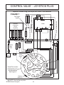
Joystick Console Plug (Old Style) w/2 Push / Pull Switches
FIGURE 7
Grn
2
C
Red
K
8
5
3
P
R
B
Red
B
7
M
L
A
D
F
H
X
G
Wht/Red
Gry/Blk
Wht/Blk
Push/Pull
Master
Switch
T
Org/Blk
Brn/Blk
B
12
A
Rocker Switches
M
Z-Output
1
Y-Output
- Negative
+ Positive
X-Output
J
6
4
Valve
Danfoss
Command
Circuit
(Joystick)
W
N
S
Push/Pull Motor Switch
Wht/Violet
Violet
Dbl Trigger
Switch
Red
Wide
Notch
(1)
J
K
H
L
B
X
C
G
A
W
Actual Pin Location
IS SHOWN for Plug
in this illustration,
See Figure 6
D
N
F
Narrow
Notch (2)
MACHETE (Service Manual) 04/04
P
E
V
U
© 2004 Alamo Group Inc.
M
R
T
23
S
E
CONTROL VALVE - JOYSTICK PLUG
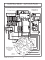
Joystick (New Style) w/ Push/Pull Motor Switch & Rocker Master Switch
C
K
Wht/Blk
B
E
Red
7
3
R
N
D
Ign
Acc
B
Brn/Blk
Org/Blk
Pwr
Motor Push / Pull
Switch With
D
Momentary Start
G
K
J
Wide
Notch
(1)
H
X
Actual Pin Location
IS SHOWN in this
Illustration, See
Figure 6
B
G
M
N
A
D
W
Narrow
Notch (2)
L
C
P
F
E
V
U
R
S
T
MACHETE (Service Manual) 04/04
© 2004 Alamo Group Inc.
Motor
Relay
X
Wht/Red
5
2
T
T
B
X
X
1 3 4 6
X
D
8
5
1
B
Grey/Blk
7
6
4
10 AMP
Grnd
Master Switch
D
P
2
Start
X-Output
D
S
Yel
Y-Output
J
Red
- Negatve
B
Z-Output
+ Positive
Danfoss Command
Circuit (Joystick)
B
J
D C K
FIGURE 8
Grn
Rocker Switch
Violet
Wht/Violet
Dbl Trigger Switches
24
CONTROL VALVE - WIRE HARNESS PLUG
FIGURE 9
Wire Harness Plug (New Style)
Actual Pin
Location in Plug
Illustrated
Narrow
Notch (2)
P
N
R
M
S
D
L
C
E
B
U
F
J
G
H
G
Start
Solenoid
Loop
E
V
X
B
T
A
K
W
A
Wide
Notch (1)
(+)
12V
T
Piston Pump
Solenoid
R
D
(-)
Grnd
H
Blk
J
Red
Blk
U
C
L
Red
Blk
V
K
F
Red
M
W
Blk
Red
R
H
S
Grnd
2
1
3
Grnd
2
1
3
Grnd
2
1
3
Grnd
2
1
3
SWING
LIFT
DIPPER
TILT
MACHETE (Service Manual) 04/04
© 2004 Alamo Group Inc.
25
Blk
N
Soleniod Lock
Valve
Red
X
P
Grnd
2
1
3
DOOR
CONTROL VALVE - HYDRAULIC
CONTROL VALVES: (See Figure 10)
The Alamo Machete Hydraulic Control Valve is an Electro-Hydraulic (Electric over Hydraulic) Valve. The Valve is designed to utilize Oil from the Tractors Hydraulic System. This is basically
considered a Selector Valve. Since the Tractor System is the Source of Hydraulic Supply (Hydraulic
Pressure). The Hydraulic Control Valve must be compatible with the type Tractor System being
utilized. There are two types of Tractor Hydraulic System available to be used (Note: in some cases
even these two type systems can vary from Tractor to Tractor Model, and make connections
different. See original Mount Kit Instruction for Connecting Hydraulic Supply from Tractor to Valve).
Type 1.
Type 2.
Load Sensing (Closed Center) Constant Pressure with Flow on demand.
Fixed Displacement (Open Center) Continuos Flow with Pressure on demand
Valve Shown Below use 1998 & Up, it has 5 Plugs on Wire Harness that plug onto Valve. Old Style
Valve used 1997 & Down had 10 Plugs on wire Harness, 5 on each side of Valve. Also the late Model
has an added Filter Assembly (P/N 02976066) which was added to protect Valve from contamination from Tractor Hydraulic System. This is a Spin on type Filter.
Pressure Port
Pressure Gauge
Port
Tank Port
Inlet Section
P
A
5 Spool
Valve
(Handles
Shown as
Illistration
Only)
T
B
Swing
A
B
Lift
A
B
Dipper
A
B
Tilt
B
Door
A
(This Valve Used 1998 & Up)
FIGURE 10
MACHETE (Service Manual) 04/04
© 2004 Alamo Group Inc.
26
CONTROL VALVE - HYDRAULIC
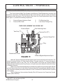
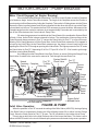
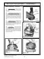
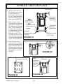
CONTROL VALVE COMPONENTS: Fixed Displacement Valve End Cap
The Control Valve for Both Type Systems (Load Sense or Fixed Displacement) consists of the
same basic components. The Difference between the Control Valves for the two systems involves the
components in the Inlet Section. The Inlet Section (End Cap) of the Fixed Displacement (Open Center)
Valve (Figure 11) contains the following components.
1.
3.
Pressure Bypass Adjustment Spool
Pressure Relief Valve
2.
4.
Pilot Reducing Valve
Load Sense Passage Plug
FIXED DISPLACEMENT VALVE END CAP
Pressure Relief
Pilot Reducing Valve
Tank Port ("T")
Pressure Port ("P")
Pressure Gauge Port
Plug
Shuttle Valve Circuit
Pressure Bypass Adjustment Spool
FIGURE 11
When the Tractor is Started and the Main Spool in the 5 Sections of the Control Valve are in The
Neutral (Centered) Position, Oil Flows from the Pump, Through connection “P” across the pressure
bypass adjustment spool to the Tank. The Oil Flow which is led across the Pressure Bypass
Adjustment Spool determines the Pump Pressure. (Pump Pressure at the Neutral Position will be equal
to Standby Pressure).
When one or more of the Main Spools are activated, the Load Pressure is fed through the Shuttle
(or Load Sense) Valve Circuit to the Spring Chamber behind the Pressure Bypass Adjustment Spool.
This completely or partially closes the connection to Tank; This allows Oil Pressure to flow to Cylinders
when needed.
The Pilot Reducing Valve maintains Standby (Pilot) Oil Pressure to the Proportional Control
System (200 to 250 PSI)
MACHETE (Service Manual) 04/04
© 2004 Alamo Group Inc.
27
CONTROL VALVE - HYDRAULIC
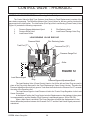
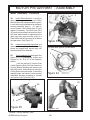
CONTROL VALVE COMPONENTS: Load Sensing Valve End Cap
The Control Valve for Both Type Systems (Load Sense or Fixed Displacement) consists of the
same basic components. The Difference between the Control Valves for the two systems involves the
components in the Inlet Section. The Inlet Section (End Cap) of the Load Sensing (Closed Center) Valve
(Figure 12) contains the following components.
1.
3.
5.
Pressure Bypass Adjustment Spool
Pressure Relief Valve
Load Sense Orifice
2.
4.
Pilot Reducing Valve
Load Sense Passage Outer Plug
LOAD SENSING VALVE END CAP
Pressure Relief
Pilot Reducing Valve
Tank Port ("T")
Pressure Port ("P")
Pressure Gauge Port
Orfice
FIGURE 12
Load Sense Signal
Plug
Pressure Bypass Adjustment Spool
The Load Sensing Valve (Closed Center) Version, An Orifice with an Outer Plug are used in
place of the Plug which was used in the Fixed Displacement (Open Center) Version. Therefore the
Pressure Adjustment Spool will only open to Tank when the Pressure in the Pressure Port “P” exceeds
the value of the Pressure relief.
The Load Sense Signal or Load Pressure is led to the Tractor Pump Regulator via the Load
Sense Connection.
In the Neutral Position the Pump Control sets the Displacement so that leakage in the system
is compensated for and the Standby (Pilot) Pressure is maintained (approx. 200 to 250 PSI).
When a Main Spool is activated, The Pump Regulator will adjust the displacement so that
the set differential pressure between the Pressure Port “P” and the Load Sense Signal pressure is
maintained.
MACHETE (Service Manual) 04/04
© 2004 Alamo Group Inc.
28
CONTROL VALVE - HYDRAULIC
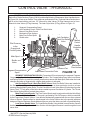
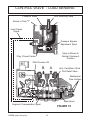
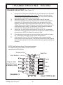
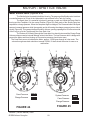
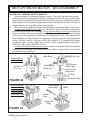
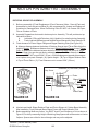
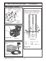
CONTROL VALVE COMPONENTS: Valve Section Components
Each of the 5 Valve Sections (Figure 13 & 14) contains the following Components. Note: Handles shown
in Figure 13 & 14 are not on Valves, They are shown as Illustration Only, On Actual Valve Section there
will be a Hex Head sticking out here, 1/2" Wrench for older Valves (10 Plug Harness) and a 9 mm
Wrench for later Valves (5 Plug Harness). The Later Style Valve (5 Plug) Shown in Figure 13.
1.
2.
3.
4.
5.
6.
Segment Compensating Spool
Anti-Cavitation Check / Work Port Relief Valve
Manual Over Ride Control
Mechanical Flow Limiters
Main Flow Control Spool
Shuttle valve
B
A
Anti-Cavitation /
Work Port Relief
Valve
Pilot Pressure
to the
Proportional
Control System
Manual
Control
Handle
Illustration
Only
Main Spool
Shuttle
Valve
Pressure Port
Segment Compensation
Spool
Load Sense Connection Ports
Mechanical
Flow Limiters
FIGURE 13
SEGMENT COPENSATING SPOOL, Pressurized Oil must pass by the segment Pressure
Compensating Spool before it is used by the Cylinders. The Compensating Spool uses Load Sense
and Spring Pressure to maintain constant pressure drop across the Main spool, Both when the Load
changes and when a Segment with a higher load pressure is activated.
Anti-Cavitation Check / Work Port Relief Valves, Work Port Relief Valves are installed in
the Swing, Lift and Dipper Circuits to limit the max pressure in those particular circuits to a lower
pressure than the Main System Relief. The Anti-Cavitation Check Valve allows Oil to be taken from the
return (Tank “T” Port) galley of the Valve when needed to prevent Cavitation of Cylinder. The Tilt and
Door Valve Sections do not contain these valves.
Main Flow Control Spools, The Flow Control Spools work in conjunction with the Valve Body
to direct the flow of Oil to the Cylinders. The spool is actuated by Pilot Oil Pressure, which is controlled
by the Proportional Control System. It can also be Mechanically operated with the use of an external
Lever or Wrench. Spools cannot be interchanged in the Valve Section due to the special individual
designs of Spools. Maximum Stroke Adjusters are pre-set at the factory and will not need Adjusting.
Load Sense Shuttle Valve, The Load Sense Shuttle Valve located in each Section insures
that the Load Sense Signal from the Valve Section with the highest Pressure is sent through the Load
sense Line.
MACHETE (Service Manual) 04/04
© 2004 Alamo Group Inc.
29
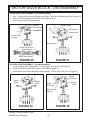
CONTROL VALVE - HYDRAULIC
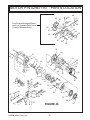
FIGURE 14
1
2
4
3
Manual Control
Handle f/ Illustration
Only
6
5
20
9 10 11
B
8
A
7
12
1
3
2 4
18
13
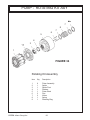
Item
1
2
3
4
5
6
7
8
9
10
17
14 15 16
Description
Pressure Relief
Pilot Reducing Valve
Load Sense signal
Pressure Gauge Port
Signal From Joystick
Orfice = Closed Center
Plug = Open Center
Pressure Bypass Adjustment Spool
Plug
Electric Controller
Spool Position Signal
Item
11
12
13
14
15
16
17
18
19
20
MACHETE (Service Manual) 04/04
© 2004 Alamo Group Inc.
30
19
Description
Pilot Pressure Flow
Anti-Cavitaion / Work Port Relief Valve
Pilot Pressure Control valve
Main Spool Position Transducer
Shuttle valve
Segment Compenstaion Spool
Pressure Port
Mechanical Flow Limiters
Main Spool
Manual Control Handle (illustration Only)
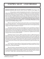
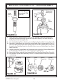
CONTROL VALVE - LOAD SENSING
GENERAL INFORMATION: Load Sensing Valve
The “Load Sensing” (Closed Centered) Systems are Commonly used on Tractors that
may employ either Fixed Displacement or Variable Displacement Pumps.
The Load Sense Feature may control Pump Output or in the case of the Fixed
Displacement Pump, Simply control delivery to the control Valve returning surplus Oil to the
tank.
The Goal of either System is to reduce wasted energy, wear and tear from pumping Oil
under Pressure when there is no demand on the system.
For the Purposes of this Manual, A Load Sense System will be defined as any system
that varies the Flow of Oil to Control Valve based on a demand signal sent through a separate
Load Sense Circuit, Closed Center System may or may not be load sensing systems.
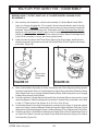
ENGINE RUNNING AND ALL FLOW CONTROL VALVES CENTERED:
(See Figure 15)
Oil from the Pump enters the Control Valve at the “P” (Pressure) Port on the Inlet Section
(End Cap) and is available at each Flow Control Spool, The Pilot Reducing Cartridge and the
Main Relief Valve. Oil flow is blocked by the Flow Control Spools, The Proportional Control
System Valves and the Main Relief Valves.
Pressure at Neutral will normally be referred to a “Standby Pressure” and will be at least
200 to 250 PSI in order to maintain Pilot Pressure. Oil passes through the Pilot Reducing
Cartridge and is blocked at each Proportional Control Valve. The Pilot Reducing Valve maintains
200 to 250 PSI in the Pilot Circuit.
The Main Relief is located in the Inlet Section (End Cap) of the Valve and limits the
Pressure in the “P” Port to a maximum 2700 PSI.
The Load Sense Circuit is connected to the Return “T” Circuit when all Spools are in the
Neutral (centered) Position.
With the Flow Control spools in their Neutral (centered) position, Oil Flows to and from
the Cylinder is blocked by the Spool. The centering of the Spool connects the Load Sense circuit
to the Return “T” Galley in the Control Valve. Since there is no Load Sense Signal being sent to
the Pump, The Pump only delivers enough Oil to maintain Pilot Pressure.
MACHETE (Service Manual) 04/04
© 2004 Alamo Group Inc.
31
CONTROL VALVE - LOAD SENSING
Pilot Reducing Valve
Pressure Relief
Return to Tank "T"
Load Sense
Signal
Pressure Bypass
Adjustment Spool
Valve is Shown In
Neutral (Centered)
Position
Plug, Closed Center
Pilot Pressure Oil
A
B
1
3
2
4
Anti - Cavitation / Work
Port Relief Valve
Mechanical
Flow Limiters
Main Spool
Segment Compensation Spool
FIGURE 15
MACHETE (Service Manual) 04/04
© 2004 Alamo Group Inc.
32
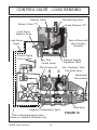
CONTROL VALVE - LOAD SENSING
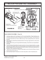
ENGINE RUNNING AND VALVE FUNCTION ACTIVATED: (See Figure 16)
When a function is selected and actuated by the controller, The Proportional Control
System directs the Pilot Pressure Oil to move the Main Spool in its bore. Two actions resulting from
the Main Spool Shifting in its bore now takes place. The Shifting of the Spool opens a passage to
connect one end of the selected Cylinder to Pressure (“P”) Galley and connect the other end to the
Return (“T”) Galley. The Shifting Spool also connects the Load Sense Circuit to the Pressure (“P”)
Circuit. The Pressure Signal is sent to the Pump Control System, which increases the Oil Flow to the
Control valve. The Pressure present in the (“P”) circuit and the Load Sense Circuit is the same
and is created by the Load on the Cylinder. (NOTE: The Load Sense Signal Shown in Figure
16 is an internal passage in Valve, it is shown here on the outside for illustration onlr and
cannot be seen if actually looking at valve).
Before the Pressurized Oil reaches the Flow Control Spool, it must first pass through the
Segment Compensation Spool. The Compensating Spool uses Load Sense and Spring Pressure
to maintain constant pressure drop across the Main spool, Both when the Load changes and when
a Segment with a higher load pressure is activated.
The maximum Pressure in the Swing, Lift and Dipper Circuits is controlled by the settings of
the Work Port Relief Valves of these Circuits. These Settings may be different for opposite ends of
the same Cylinder or Circuit. The Cartridge also incorporates Anti - Cavitation Check Valves to provide
make up Oil if required. These Valves will open to allow Oil from the Tank Galley to enter the Cylinder
whenever there is no more Oil being demanded by a Cylinder than is supplied (Such as with the
Lowering Function) in order to prevent Cavitation.
Proportional Control of the Lift, Dipper and Swing Functions is achieved through the
Proportional Control System of each Section (Tilt and Door Functions DO NOT have Proportional
Control, they are “Open” or “Closed” only). When an Electrical Signal is sent from the Joystick to the
Electric Controller in the Valve, The Pilot Pressured Oil is then allowed to flow to either end of the Spool
thus causing it to shift. The amount Pilot Pressured Oil to either end of Spool is varied with the Pilot
Oil Control Valve by the Electric Controller there by controlling the distance the Spool Shifts. This in
turn controls the volume of Oil sent to the Cylinders and consequently, the speed of actuation of the
Cylinders.
The Tilt and Door Functions (While not Proportionally Controlled) are controlled by Pilot Oil
Control Valves. However instead of opening or closing based on the Joystick position, these valves
will fully Open (or Close) when activated.
When the Function is returned to Neutral at the Joystick, The electrical current to the Valve
Controller is stopped. Therefore the Pilot Oil Control Valves return to their normal positions and the
flow of Pilot Pressure Oil to the Main Spool is stopped. The Springs on the Main Spool returns the Spool
to its Neutral (Centered) position. When the Spool is centered, The Load Sense Circuit is connected
to the Tank (“T”) Galley. With no Load Sense Signal, Pump returns to minimum.
MACHETE (Service Manual) 04/04
© 2004 Alamo Group Inc.
33
CONTROL VALVE - LOAD SENSING
Pressure Relief
Pilot Reducing Valve
Return to Tank ("T")
Pump Pressure ("P")
Load Sense
Signal to Pump
Load Sense
Signal
Valve is Shown with
Valve Function
Activated
Position Signal
From Joystick
Pressure Bypass
Adjustment Spool
Plug,
Closed center
Pilot Pressure Oil
B
A
Anti - Cavitation / Work
Port Relief Valve
Mechanical
Flow Limiters
Segment Compensation Spool
FIGURE 16
This is internal passage in Valve,
Shown on outside for illustration only
MACHETE (Service Manual) 04/04
© 2004 Alamo Group Inc.
Main Spool
34
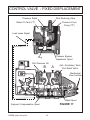
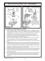
CONTROL VALVE - FIXED DISPLACEMENT
GENERAL INFORMATION: Fixed Displacement Valve
The “Fixed Displacement” (Open Centered) Systems Control Valve is designed to be
used on tractors that DO NOT have Load Sense (Closed Centered) Hydraulic Systems.
ENGINE RUNNING AND ALL FLOW CONTROL VALVES CENTERED:
(See Figure 17)
Oil from the Pump enters the Control Valve at the “P” (Pressure) Port on the Inlet Section
(End Cap), If there are no other Hydraulic functions being used; all of the flow from the Fixed
Displacement Pump must go through the Control Valve. The Flow of Oil is blocked by the Flow
Control Spools in each Valve Section, The Main Relief Valve, The Proportional Control System
valves, The Load Sense Passage Plug and the Bypass Adjustment Valve. The first Circuit to
be charged is the Pilot Circuit, Oil passes through the Pilot Reducing Cartridge which limits the
Pressure in the Circuit to approximately 200 PSI.
After the Pilot Circuit is charged, Additional Oil being pumped into the Valve increases
the pressure in the pressure (“P”) Circuit. When in Neutral, The Pressure in the pressure (“P”)
Circuit is limited to approximately 215 PSI by the Pressure Bypass Adjustment Valve Spring.
When the Pressure in the (“P”) circuit is enough to overcome the force of the Bypass Spring,
the Bypass Spool is shifted in its bore, Opening a passage between the Pump Oil (“P”) Circuit
and the Return (“T”) Circuit. The Bypass Spool maintains enough pressure (Pilot Pressure) in
the System to actuate the Flow Control Spools and returns any surplus Oil to Tank.
When the Flow Control Spools are centered (Neutral), the Load Sense Passage works in
conjunction with the Bypass Spring to limit the Main System Pressure in Circuit (“P”). Since
there is no pressure in the Load Sense Passage in Neutral (Centered) the force of the Spring
is the only factor determining System Pressure.
NOTE: The Load Sense Passage shown in figure 17 is an internal passage inside of Valve and
cannot be seen if looking at Valve, It is shown here outside Valve as Illustration Only.
MACHETE (Service Manual) 04/04
© 2004 Alamo Group Inc.
35
CONTROL VALVE - FIXED DISPLACEMENT
Pressure Relief
Pilot Reducing Valve
Pressure From
Pump ("P")
Return To Tank ("T")
Load sense Signal
Pessure Bypass
Adjustment Spool
Plug
Pilot Pressure Oil
B
A
Anti - Cavitation / Work
Port Relief Valve
Mechanical
Flow Limiters
1
3
2 4
Main Spool
FIGURE 17
Segment Compensation Spool
MACHETE (Service Manual) 04/04
© 2004 Alamo Group Inc.
36
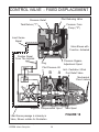
CONTROL VALVE - FIXED DISPLACEMENT
ENGINE RUNNING AND VALVE FUNCTION ACTIVATED: (See Figure 18)
When a function is selected and actuated by the Controller, The Proportional Control
System directs the Pilot Pressure Oil to move the Main Spool in its bore. Two actions resulting from
the Main Spool Shifting in its bore now take place. The Shifting Spool opens a Passage to connect
one end of the selected Cylinder to the Pressure (“P) Galley and connect the other end to the Return
(“T”) Galley. The Shifting Spool also allows the Load Signal created by gravity acting on the Cylinder
to connect to the Spring end of the Pressure Bypass Adjusting Spool. This acts with the Spools
spring to close the Passage to the Tank (“T”), and allows the correct amount of Oil to travel to the
Cylinders. Based on the Load Sense Pressure, The Pressure Bypass Adjustment Spool will allow
only the Oil needed at the Cylinder in accordance with the Controllers Position. Any excess Oil will
be allowed to return to Tank (“T”). The Pressure present in the (“P”) Circuit and the Load Sense
Circuit is the same and is created by the Load on the Cylinder.
Before the Pressurized Oil reaches the Flow Control Main Spool, It must first pass through
the Segment Compensation Spool, this Spool maintains a constant pressure differential (Flow)
between the Supply Pressure and the Cylinder Pressure at the Flow Control Main Spool. (Simple
Explanation: Function of Segment Spool is to keep a constant even pressure to Main Spool so
Cylinder cannot suck in Air).
The maximum Pressure in the Swing, Lift and Dipper Circuits is controlled by the settings
of the Work Port Relief Valves for these Circuits. These settings may be different for opposite ends
of the same Cylinder or Circuit. The Cartridge also incorporate Anti - Cavitation Check Valves to
provide make up Oil if required. These Valves will open to allow Oil from the tank Galley to enter the
Cylinder when ever there is no more Oil being demanded by a Cylinder than is supplied (Such as
with Lowering function) in order to prevent Cavitation.
Proportional Control of the Lift, Dipper and Swing Functions is achieved through the
Proportional Control System of each section. When an electrical signal is sent from the Joystick
to the Electric Controller in the Valve, The Pilot Pressured Oil is then allowed to flow to either end
of the Spool thus causing it to shift. The amount of Pilot Pressured Oil to either end of Spool is varied
with the Pilot Oil Control Valve by the Electric Controller there by controlling the distance the Spool
Shifts. This in turn controls the volume of Oil sent to the Cylinders and consequently, the Speed of
activation of the Cylinders.
The Tilt and Door Function, While not proportionally controlled are controlled by Pilot Oil
Control Valves. However instead of opening or closing based on Joystick Position, These Valve will
fully open or fully closed when activated, Tilt and Door Functional are not proportional they are open
full or closed full only.
When the Function is returned to Neutral at the Joystick, The Electrical current to the Valve
Controller is stopped. There fore the Pilot Oil Control Valves return to their normal positions and the
Flow of Pilot Pressure Oil to the Main Spool is stopped. The Springs on the Main Spool returns the
Spool to its centered (Neutral) Position. When the Spool is centered the Load Sense Signal stops.
With no Load Sense Signal present the Pressure Bypass Adjustment Spool allows most of the Oil
in the Pressure (“P”) Port to return to the Tank (“T”). The Pilot Reducing Valve retains Pilot (Standby)
Pressure in the Valve.
MACHETE (Service Manual) 04/04
© 2004 Alamo Group Inc.
37
CONTROL VALVE - FIXED DISPLACEMENT
Pilot Reducing Valve
Pressure Relief
Pressure From
Pump ("P")
Tank Return ("T")
Load Sense
Signal
Valve Shown with
Function Activated
Position Signal
From The Joystick
Pressure Bypass
Adjustment Spool
Plug
Pilot Pressure Oil
B
A
Anti - Cavitation / Work
Port Relief Valve
Mechanical
Flow Limiters
1
2
3
4
Segment Compensation Spool
FIGURE 18
Load Sense passage is internaly in
Valve, Shown outside for Illustration
MACHETE (Service Manual) 04/04
© 2004 Alamo Group Inc.
Main Spool
38
NOTES
MACHETE (Service Manual) 04/04
© 2004 Alamo Group Inc.
39
SWING
DIPPER
TILT
DOOR
LIFT
VALVE ASSEMBLY
Load Sense
P/N 02968851
May 1995
to
Dec.1997
S/N MB21-01001
S/N MB24--01001
to
S/N MB21-01109
S/N MB24--01046
VERY IMPORTANT
DO NOT Use Solenoids
as Handles
5
5,6,8 See Detail A
4
C2
1,9
2
3
Load Sense
Port
5.6.8
See Detail A
C1
5,7,8 See Detail A
NOTE: Make Certain That
Orfice Plate # 6 Goes to Swing Port C2
Orfice Plate # 7 Goes to Swing Port C1
Orfice Plate # 6 Goes to Tilt Plate Port C1
5
DETAIL A
5
6 or 7
8
To Valve
MACHETE (Service Manual) 04/04
© 2004 Alamo Group Inc.
Notch in Orfice Plate
Must Face away from
Valve as Shown
40
VALVE ASSEMBLY
Load Sense
P/N 02968851
May 1995
to
Dec 1997
Item Part No.
1
2
3
4
5
6
7
8
9
02968851
02761100
02822300
02960018
02967201
02968850
02969398
02969399
02969400
63042700
S/N MB21-01001
S/N MB24--01001
to
S/N MB21-01109
S/N MB24--01046
Qty
Description
-2
2
ref
1
8
2
1
3
2
Valve Asy. 5 Spool (Load Sense)
Adapter, Elbow, 90 Deg.
Adapter, Straight
Adaptor ,Elbow, 90 Deg.
Valve, Load sense, 5 Spool
Adapter, Straight
Orfice, for C2 Port, .055 Dia. Hole
Orfice, for C1 Port, .040 Dia. Hole
Adapter, Straight
Adapter, Straight
NOTE: To help ID Valve, The Wiring Harness on this valve has
10 Plugs, 5 on each side of the valve, The later version will only
have 5 plugs and they are only on one side of the valve
MACHETE (Service Manual) 04/04
© 2004 Alamo Group Inc.
P41
VALVE ASSEMBLY
Load Sense
P/N 02972175
Jan. 1998
to
Sep. 2000
S/N MB21-01110
S/N MB24--01047
to
S/N MB21-01571
S/N MB24--01246
16
17
5,6,12
See Detail A (.070)
5,6,13
See Detail A (.055)
SWING LIFT DIPPER TILT
DOOR
18
4
7
2,3
1
8
5,6,14
See Detail A (.040)
7
5,9,10,13,15
See Detail
A & B(.055)
5,6,11
See Detail A (.063)
21
19
Note orientation
of notch in plate
20
6 or 9
15
11,12,13 or 14
5,9,13
5
10
To Valve
DETAIL A
DETAIL B
MACHETE (Service Manual) 04/04
© 2004 Alamo Group Inc.
42
VALVE ASSEMBLY
Load Sense
P/N 02972175
Jan 1998
to
Sep. 2000
Item
Part No.
Qty
Description
1
2
3
4
5
6
7
8
9
10
11
12
13
14
15
16
17
18
19
20
21
02972175
02971378
63042700
02761100
02972178
02972113
02968850
02972177
02972179
02972180
001654
02972209
02972210
02969398
02969399
02972208
02974004
02974005
02974027
02974838
02975598
02975599
1
2
2
1
5
4
3
2
1
1
1
1
2
1
1
2
3
5
5
1
1
Valve Asy. 5 Spool
Valve, 5 Spool CCLS
Adaptor, Straight
Adaptor, Elbow 90°
Adapter, Elbow 90°
Adaptor, Straight
Adapter, Straight
Adapter, Straight
Adaptor, Straight
Adaptor, Straight
Adaptor, Elbow 90 Deg
Orifice, .063
Orifice, .070
Orifice, .055
Orifice, .040
Solenoid Lock Valve Asy
Electric Activation Module
Electric Activation Module
Seal Kit, O-Ring
Mech. Activation Module
Coil
Cartridge
S/N MB21-01110
S/N MB24--01047
to
S/N MB21-01571
S/N MB24--01246
NOTE: To help ID Valve, The Wiring Harness on this valve has
only 5 Plugs, 5 only on 1 side of the valve, The Earlier version
will have 10 plugs, and they are 5 on each side of the valve.
MACHETE (Service Manual) 04/04
© 2004 Alamo Group Inc.
P43
VALVE ASSEMBLY
Load Sense
P/N 02976688
Oct. 2000
to
Current
S/N MB21-01572
S/N MB24--01247
to
S/N MB21-Current
S/N MB24--Current
4,5,11,15
0.070 Orfice*
4,5,12,15
0.055 Orfice*
6,15
14,19
LIFT
SWING
LS
B
DIPPER
B
B
6,15,17
TILT
DOOR
3,7,14
B
B
T
2
P
1
A
A
A
A
3,7,14
4,5,15,18
0.040 Orfice*
6,15
4,5,10,15
0.063 Orfice*
*Note: Orientation of
Notch in Plate must be
notch up as shown
4,5,8,12,13,15,16
0.055 Orfice *&
Lock Valve
9,15
5 or 8
13
16
8
4,12
10, 11, 12 or 18
4
To Vakve
Orfice Plate
Solinoid Lock Valve
DETAIL A
DETAIL B
MACHETE (Service Manual) 04/04
© 2004 Alamo Group Inc.
44
VALVE ASSEMBLY
Load Sense
P/N 02976688
Oct. 2000
to
Current
Item Part No.
1
2
3
4
5
6
7
8
9
10
11
12
13
14
15
16
17
18
19
02976688
02971378
63042700
02976532
02972113
02968850
02972177
02972179
02962213
02968850
02972209
02972210
02969398
02972208
02957416
02963637
02975438
02976531
02969399
02972178
Qty
Description
1
1
1
5
4
3
2
1
1
1
1
2
1
3
8
1
1
1
1
Assembly Valve, 5 Spool
5 Spool Valve CCLS
Adaptor, Straight
Adaptor, Elbow 90°
Adapter, Straight
Adapter, Straight
Adapter, Straight
Adaptor, Straight
Adaptor, Elbow 90°
Adp, Hyd. Straight
Orifice, .063
Orifice, .070
Orifice, .055
Solenoid Lock Valve Assy
Cap, Plastic Female
Cap, Plastic Outer
Adp Hyd Stght
Adp Hyd Elbow
Orifice, .040
Adp Hyd Elbow
S/N MB21-01572
S/N MB24--01247
to
S/N MB21-Current
S/N MB24--Current
NOTE: To help ID Valve, Note the difference in detail B from
earlier Valve, The location of components in detail B. Lock Valve
MACHETE (Service Manual) 04/04
© 2004 Alamo Group Inc.
P45
SWING
LIFT
TILT
DOOR
DIPPER
VALVE ASSEMBLY
Fixed Displ.
P/N 02968854
May 1995
to
Dec 1997
S/N MB21-01001
S/N MB24--01001
to
S/N MB21-01109
S/N MB24--01046
VERY IMPORTANT
DO NOT Use Solenoids
as Handles
4
4
3
C2
5,1
2
4,6,7
See Detail A
C1
4
4
DETAIL A
4
6
7
To Valve
Notch in Orfice Plate
Must Face away from
Valve as Shown
MACHETE (Service Manual) 04/04
© 2004 Alamo Group Inc.
46
VALVE ASSEMBLY
Fixed Displ.
P/N 02968854
May 1995
to
Dec. 1997
S/N MB21-01001
S/N MB24--01001
to
S/N MB21-01109
S/N MB24--01046
Item
Part No.
Qty
Description
1
2
3
4
5
6
7
02968854
02761100
02822300
02968533
02968850
63042700
02969398
02969400
-2
2
1
8
2
2
1
Valve Asy. 5 Spool, OCFD
Adapter, Elbow, 90 Deg.
Adapter, Straight
Valve,Fixed Displ., 5 Spool
Adapter, Straight
Adapter, Straight
Orfice, .055 Dia. Hole
Adapter, Straight
MACHETE (Service Manual) 04/04
© 2004 Alamo Group Inc.
P47
Jan. 1998
to
Sep. 2000
VALVE ASSEMBLY
Fixed Displ.
P/N 02972176
S/N MB21-01110
S/N MB24--01047
to
S/N MB21-01571
S/N MB24--01246
14
15
4,5,11
See Detail A (.070)
6
SWING LIFT DIPPER TILT
DOOR
16
6
2,3
1
7
6
6
4,8,9,12,13
See Detail
A & B(.055)
4,5,10
See Detail A (.063)
19
17
Note orientation
of notch in plate
18
6 or 8
13
10,11,or 12
4,8,12
4
10
To Valve
DETAIL A
DETAIL B
MACHETE (Service Manual) 04/04
© 2004 Alamo Group Inc.
48
VALVE ASSEMBLY
Fixed Displ.
P/N 02972176
Jan. 1998
to
Sep. 2000
Item
Part No.
1
2
3
4
5
6
7
8
9
10
11
12
13
14
15
16
17
18
19
02972176
02971379
63042700
02761100
02972113
02968850
02972177
02972179
02972180
001654
02972209
02972210
02969398
02972208
02974004
02974005
02974027
02974838
02975598
02975599
MACHETE (Service Manual) 04/04
© 2004 Alamo Group Inc.
Qty
Description
1
2
2
3
2
5
2
1
1
1
1
2
1
2
3
5
5
1
1
Valve Asy. 5 Spool
Valve, 5 Spool OCFD
Adaptor, Straight
Adaptor, Elbow 90°
Adapter, Straight
Adaptor, Straight
Adapter, Straight
Adaptor, Straight
Adaptor, Straight
Adaptor, Elbow 90 Deg
Orifice, .063
Orifice, .070
Orifice, .055
Solenoid Lock Valve Asy
Electric Activation Module
Electric Activation Module
Seal Kit, O-Ring
Mech. Activation Module
Coil
Cartridge
P49
S/N MB21-01110
S/N MB24--01047
to
S/N MB21-01571
S/N MB24--01246
VALVE ASSEMBLY
Fixed Displ.
P/N 02976533
Oct. 2000
to
Current
S/N MB21-01572
S/N MB24--01247
to
S/N MB21-Current
S/N MB24--Current
4, 5, 11, 15
0.070 Orfice*
6, 15
6,15
LIFT
SWING
B
DIPPER
B
B
6, 15, 17
TILT
DOOR
3, 7, 14
B
B
T
2
P
1
A
A
A
A
3, 7, 14
6, 15
6, 15
4, 5, 8, 12, 13, 15, 16
0.055 Orfice *& Lock
Valve
4, 5, 10, 15
0.063 Orfice*
*Note: Orientation of
Notch in Plate must be
notch up as shown
9,15
5 or 8
13
16
8
4,12
10, 11, or 12
4
To Vakve
Orfice Plate
Solenoid Lock Valve
MACHETE (Service Manual) 04/04
© 2004 Alamo Group Inc.
50
VALVE ASSEMBLY
Fixed Displ.
P/N 02976533
Oct. 2000
to
Current
Item Part No.
1
2
3
4
5
6
7
8
9
10
11
12
13
14
15
16
17
02976533
02971379
63042700
02976532
02972113
02968850
02972177
02972179
02962213
02968850
02972209
02972210
02969398
02972208
02957416
02963637
02975438
02976531
Qty
Description
1
1
1
1
4
3
2
1
1
1
1
2
1
2
8
1
1
Assembly Valve, 5 Spool
5 Spool Valve OCFD
Adaptor, Straight
Adaptor, Elbow 90°
Adapter, Straight
Adapter, Straight
Adapter, Straight
Adaptor, Straight
Adaptor, Elbow 90°
Adp, Hyd. Straight
Orifice, .063
Orifice, .070
Orifice, .055
Solenoid Lock Valve Assy
Cap, Plastic Female
Cap, Plastic Outer
Adp Hyd Stght
Adp Hyd Elbow
MACHETE (Service Manual) 04/04
© 2004 Alamo Group Inc.
P51
S/N MB21-01572
S/N MB24--01247
to
S/N MB21-Current
S/N MB24--Current
Control Valve
Trouble Shooting
Section
Machete (Service Manual) 04/04
© 2004 Alamo Group Inc.
53
TROUBLE SHOOTING - BEGIN
MACHETE CONTROL VALVE
HYDRAULIC SYSTEM - POSITIONING - TEST PROCEDURES
NOTE: The Machete is equipped with manual override controls for the Control Valve. In case of
Emergency Electrical failure or for testing purposes, The positioning Hydraulics can be operated
manually. Refer to Isolation Test 2 for instructions or review Control Valve Section.
IMPORTANT NOTE:
1.
Repairing a failed Component is not always repairing the Cause of a failure,
When making repairs always check all associated components because one
component can be the cause of another component failure.
INFORMATION COLLECTION: Any information on Unit from operator will be helpful.
1.
2.
3.
4.
5.
6.
7.
8.
9.
10.
What is Model Unit, Size, Type Head, Type Tractor it is mounted on etc?
What is not working correctly? In as much detail as possible.
Has this malfunction existed for some time, just start suddenly, continuos
malfunction or off and on, when does malfunctions occur.
Did this malfunction result from an earlier malfunction? What if any repairs,
adjustment, modifications or any changes to any components have been made
to unit recently. (Repairs - Maintenance - Accidents - Operator Change)
Have all the obvious items been checked, Oil Levels (Tractor & Unit Reservoirs),
Electrical Supply (Dead Battery, Loose connections, etc.)
Does the malfunction affect all circuits, one, two or more?
Does malfunction affect both sides of the same function or just one (Example Lift
& Lower, in or out, etc)
Does malfunction happen when Cold or Hot, only Cold or only Hot, more when
Cold than Hot, more when Hot than Cold etc.
What Conditions? What is Unit doing when malfunction occurs, running at low?
RPM, High RPM, heavy Cutting, light Cutting, Level Ground, Slope Angle etc.
Any information that will help determine what may be causing the Malfunction or
to pin point the location of the malfunction.
VISUAL TEST:
1.
2.
Do Not Start Tractor till all visual inspections are done. Check All Fluid Levels
(Fluid Levels should be checked with oil warm and with all components filled
with Oil from operation), Remove any bolt on / Slip on Cover that prevent visual
inspection of general condition of components. Look for any Broken Components, Missing Components, Loose Components, Oil Leaks, Damaged Components. Look for any thing that is obvious to cause a problem.
Replace any missing / broken components, tighten any loose components,
repair any Oil Leaks before beginning any further test.
Machete (Service Manual) 04/04
© 2004 Alamo Group Inc.
54
TROUBLE SHOOTING - TESTING
OPERATIONAL TEST:
1.
2.
3.
4.
5.
6.
7.
8.
Visual Test should have been done already, If not go back one page and perform
visual test now. Pump and/or Valve covers should be removed.
Start Tractor Engine, When starting Machete Boom functions always listen to
sound of Engine, Sound should change when Boom Hydraulics are in the
working position.
With Tractor Engine running operate each Circuit, Paying close attention to
every thing the unit does or does not do.
The Engine speed should drop (the Sound Change) when the Valve spool
moves and the Pump comes under a load, If the Engine sound does not change
when the Circuit is activated (on a Load Sense System) it is an indication that
there is a possible malfunction in the Load Sense Circuit.
Observe each function of the Joystick control throughout its complete range of
movement. Check the Cylinder speeds, Look for “Jerky” operation (the Cylinder
should respond smoothly to the movement of the Joystick). Look for time delay
between movement of Joystick and movement of Cylinders.
After checking each function, attempt to duplicate the malfunction described by
Operator, Using the information gathered in the Operator Interview. If you are not
able to get machine to malfunction, see if operator can get the machine to
malfunction.
When the Malfunction occurs, take note of all conditions that exist during the time
of the malfunction, Some things to take note of are,
A.
Engine Speed or Sound.
B.
Position of Articulating Members.
C.
Operating Temperature
D.
Length of time Unit has been running
E.
Position of Joystick before and during malfunction.
F.
Position and Condition of Tractor
G.
Any other condition you might notice.
Duplicate the conditions that existed when the malfunction occurred to determine if the malfunction will occur every time that the same conditions exist. Try
different combinations of conditions to determine which conditions actually
affect the malfunction and which ones just happened to be there when the
malfunction occurred.
ISOLATION TEST 1:
1.
This test must be performed while the malfunction is occurring. This Test is used
when one or more functions are inoperative (either constant or intermittent) This
procedure applies to units utilizing a general application, Read directions as to
which series of Valve, there are early model versions and late model versions.
The following is for the late model version.
Machete (Service Manual) 04/04
© 2004 Alamo Group Inc.
55
TROUBLE SHOOTING - TESTING
ISOLATION TEST 1:
2.
3.
(Continued from previous page)
Re-check to make sure all fluid levels are OK. The Control Valve Cover should
still be removed. Make sure that the Tractor Transmission is in Neutral and the
Park Brake is set and Holding, Test Park Brake before continuing. Make sure
that Boom and Cutting Head are resting on the ground.
With the help of an assistant, One Person stand outside the Tractor in a position
to observe the Manual override control, which is 9 mm Hex head (on Later
Version, 1/2" on early models) located on each Valve Section, (See Figure 19)
The other person will operate the Joystick from the Operators Seat. If Manual
override is not moving check the electrical connections.
123456
123456
123456
123456
Manual Override
Control use 9 mm
Hex Head Wrench
12
12
FIGURE 19
4.
5.
123
123
123
1234567890
1234567890
1234567890
12345678901
12345678901
12345678901
While the malfunction is occurring, one person should actuate the Joystick while
the other observes the manual override control for that specific function (See
Figure 19). The Manual Override control should move in relation to the movement of the Joystick movement. Each Valve Section will have one of these Hex Head
Overrides.
If the Manual Override control moves properly when the Joystick is moved:
A.
The Joystick is working.
B.
Wiring Harness is OK.
C.
Solenoid valve(s) are working.
D.
Pilot Pressure Oil is Present.
E.
Valve Spools are moving.
F.
Cause is most likely in Valves, Hoses or Cylinders.
Machete (Service Manual) 04/04
© 2004 Alamo Group Inc.
56
TROUBLE SHOOTING - TESTING
ISOLATION TEST 2:
1.
This Procedure applies to Units utilizing the Late Model Control Valve Assemblies used 1998 and up.
Re-check to make sure all fluid levels are OK. The Control Valve Cover should
still be removed. Make sure that the Tractor Transmission is in Neutral and the
Park Brake is set and Holding, Test Park Brake before continuing. Make sure
that Boom and Cutting Head are resting on the ground.
Locate the manual override control on Control Valve (See Figure 20) for the
Valve circuit that is malfunctioning (or you want to test). Each Section of the Valve
has manual override control.
2.
3.
12345
12345
12345
12345
12345
Manual Override
Control use 9 mm
Hex Head Wrench
12
12
12
12
12
FIGURE 20
4.
5.
6.
7.
8.
1234567890
1234567890
1234567890
1234567890
1234567890
1234567890
Start the Engine and let the Engine run at least 1000 RPM
Using a 9 mm Open Wrench (See Figure 20) actuate the manual override
controls for the Circuit that is malfunctioning. Take note of the reaction of the
Circuit to all positions of the control. Also take note of the Smoothness of Spool
Operation. The Spool should move smoothly. If it doesn’t it can indicate contamination in the system or something wrong with Spool causing it to bind.
If the Circuit fails to work with the Joystick and works properly with the manual
override control, The problem is in the Electrical Control Circuit, The Solenoid
Valve, Joystick or Wiring Harness or Pilot Pressure.
If the circuit fails to work using the Manual Override Control, The Problem is in
the Control Valve, Hoses or Cylinder.
Use this test to determine which components to test and/or trouble shoot.
Machete (Service Manual) 04/04
© 2004 Alamo Group Inc.
57
TROUBLE SHOOTING - TESTING
SOLENOID VALVE TEST: (See Figure 21)
1.
2.
3.
4.
5.
6.
Using this test to determine if the Malfunction is in the Solenoid Valve Assembly
after having performed Isolation Test 1 and 2. This test is used when some
circuits are operating and one or more are not, The Circuit will work manually
as described in Isolation Test 2 but not electrically.
Start with the Engine “OFF” and the Control Valve Cover still removed.
Connect the Solenoid Valves of the inoperative Valve Section to the Harness
connections of a Valve section that is known to be operational (See Valve
Diagram), remember some are proportional and some are not. Connect (for
Testing) Swing, Lift and Dipper Functions (Proportional) or connect Door to Tilt
(Non-Proportional) for testing. In other words connect (Swap) the Harness
connection from Questionable Circuit with a good Circuit.
Operate the Joy stick function for Both swap Circuits, (NOTE: You swapped
connections so the movement of Joystick one way will have a different Cylinder
movement now). KEEP this different movement in Mind.
If the inoperative circuit begins to work now and the former function is inoperative, The problem most likely is in the Joystick Wiring Harness.
If the Inoperative Circuit STILL FAILS to operate, and the Known operative
circuit continues to function properly, The problem is most likely in the Solenoid
Valve (Providing that the Circuit functioned when Manually operated with Manual
Override).
NOTE: See Directions above, Disconnect connector
for malfunctioning circuit and recoonect to a known
operational circuit for testing.
Pressure Port
Inlet Section
Tank Port
P
A
5 Spool Valve
(Handles Shown
as Illistration Only)
T
B
Swing
B
Lift
A
B
Dipper
A
B
Tilt
B
Door
A
FIGURE 21
(Used 1998 & Up)
Machete (Service Manual) 04/04
© 2004 Alamo Group Inc.
58
TROUBLE SHOOTING - TESTING
The Slots are numbered:
No. 1 Positive, 12 Volts DC
No. 2 Positive, Should be 1/2 Voltage
of Slot No. 1 to Ground (6 Volts
if 12 Volts etc.) because current
is being reduced
No. 3 This Slot is not used at all Grd.
Negative, Common Ground, A
long Slot, (Not Marked ).
No.3
No.2
No.1
Grd
Harness
Plug
THE ABOVE INFORMATION IS FOR TESTING THE NEW
STYLE VALVE ONLY
USE A VOLT METER TO TEST. THE NEW STYLE CAN BE ID BY THE 5
PLUGSON ONE SIDE WHERE HARNESS CONNECTS TO VALVE, THE OLD
STYLE HAD 10 PLUGS, 5 ON EACH SIDE>
MAKE SURE
IF OLD STYLE OR NEW STYLE
VALVE IS USED BEFORE TESTING
THIS IS IMPORTANT
THE INFORMATION ON THE NEXT PAGE IS FOR TESTING OLD
STYLE VALVE ONLY
To ID Old Style Valve it will have 10 Plugs on Wiring Harness where it plugs on to Valve,
The Newer Style Only has 5, For testing new Style see Previous Pages. DO NOT USE
THESE to Test Newr Style Valves with5 Plug Harness.
Machete (Service Manual) 04/04
© 2004 Alamo Group Inc.
59
TROUBLE SHOOTING - TESTING
JOYSTICK - WIRING HARNESS TEST: (See Figure 22 & 23) Old Style Valve testing
1.
2.
Perform this Test when Isolation Test 1, Isolation Test 2 and Solenoid Valve
Test have been Completed and indicates that the cause of an inoperative or
intermittent complaint is located in the Joystick or Harness.
A Handy TIP to make a tester is shown in Figure 19, To make this tool use a
discarded Plug (or purchase one Locally) and wire a 12 volt bulb into it, If doing
a lot of testing might want to consider making one for each connection. By
making this type tester you will be able to test the positive (+) and negative (-)
connection at the same time and this would allow the test to be performed by
one person and decrease the chance of making a connection wrong. A normal
12 volt test Light can be used as shown in Figure 23, but this method normally
requires two people to perform and Test Light Must be connected correctly.
FIGURE 22
3.
4.
5.
Disconnect the Wiring Harness Connector at Valve for the inoperative Circuit
at the Valve Solenoid Connection.
Connect the Test Tool you built (or 12 Test light) to the Harness end of the connector,
(If using a test light to check a positive (+) connection be sure to ground Test Light to a
good ground connection, if testing a Negative (-) connection it would be required to
reverse the + to - Connection. (See Figure 22)
While actuating the Joystick, Test for voltage at the connect (if using Tool you
Built the Bulb should light up or test light should light up). If test light comes on
then this circuit is OK, If using a normal Test Light see Figure 23 both sides of
connection will need to be tested; this may require an assistant
(Connection for Testing Positive (+) Side Shown Below)
+
-
Swing
+
-
Lift
+
-
Dipper
TO
WIRING
HARNESS
FIGURE 23
Machete (Service Manual) 04/04
© 2004 Alamo Group Inc.
60
PUMP SECTION
Machete (Service Manual) 04/04
© 2004 Alamo Group Inc.
61
PUMP - GENERAL
INTRODUCTION:
The information in this Section of Book is re-printed with Permission of the Eaton Corp. This
Section of Book provides service information for the Servo Controlled Piston Pump P/N 02967192.
Step by Step instructions for the complete dis-assembly and re-assembly of the Pump are given. In
Most diagrams there are no Component Part Numbers Listed, Only Item numbers and Descriptions,
This is because most parts shown as break-down in drawings are for location & identification only and
are not available as replacement parts. NO Dirt at all should be around Parts during repairs.
BEFORE STARTING REPAIRS: Service Rules (READ THIS)
1.
2.
3.
4.
5.
6.
7.
8.
9.
Remove Front Cover. Clean Pump and surrounding area completely before removing
any connections or Lines. NO DIRT OR DEBRIS CAN BE ALLOWED ON OR NEAR
HYDRAULIC SYTEM IF IT IS BEING WORKED ON, ANY DIRT OR CONTAMINANTS
IN SYSTEM NO MATTER HOW SMALL WILL DAMAGE SYSTEM!
After cleaning around all connections thoroughly, Dis-connect all connections, Lines,
Hoses, Wiring and Remove the Pump Completely from the Tractor. Plug all hoses and
Lines on Tractor and on Pump, DO NOT leave any open Lines. NO Contamination
Should be allowed into system at all.
Clean Area, Clean all Tools, Pans etc. The cleaning of Area and Tools MUST be done
before moving (Cleaned) Pump there. Drain Oil from Pump, Recheck outside of
Pump to Make Sure it is Clean
After dis-assembly of Pump wash all metal components in clean solvent.
Use compressed Air to dry parts after washing (Compressed air must be filtered and
moisture free). DO NOT wipe them dry with Paper Towels or Cloth as these will leave
lint and/or dust contamination. DO NOT USE Compressed Air to spin any component
(Such as Bearings or Plates) as this will damage them and could be dangerous.
Always use new Seals when re-assembling Hydraulic Pumps, Lubricate the new
rubber Seals with a Petroleum Jelly, (Vaseline) before installing them.
DO NOT reinstall worn or damaged Parts back in Pump, DO NOT Use a worn or
damaged Pump Housing.
Torque all Bolts over Gasketed Joints. Then repeat the Torque sequence to make
sure Bolts are tight, some times Gaskets can give a Torque reading that is OK but is
not, so always re-check Torque.
Verifying the accuracy of Pump Repairs on an authorized test stand is essential.
REQUIRED TOOLS:
1.
2.
3.
4.
5.
6.
7.
8.
9.
10.
11.
12
Hex Allen Wrench (Qty 5) (9/16", 5/32", 5/16", 3/32", 5/64"
Retaining Ring Pliers (Qty 3), 1 each of Internal (Straight .070 tip) internal (Straight .090
tip) & 1 each External (Straight 0.90 tip)
Retaining E-Ring Applicator (Qty 2), 1 each 9/32" & 1 each 1/2".
O-Ring Pick (Qty 1)
End Wrench (Qty 4), 1 each of 7/16", 9/16", 3/4", 1"
Torque Wrench (Qty 1), 0 to 100 ft. lbs. (135.6 nm) capacity
Hammer, Soft Face (Qty 1)
Seal Driver Set (Qty 1)
Arbor Press (Qty 1)
Sockets (Qty 3) 7/16", 9/16", 3/4" (Drive Size should match Torque Wrench Drive)
Light Petroleum Jelly (Vaseline)
Locktite, # 222 and #277 or equivalent (Qty 1 tube each)
.
Machete (Service Manual) 04/04
© 2004 Alamo Group Inc.
62
PUMP - REPAIR TOOLS
RECOMMENDED GAUGES FOR DIAGNOSTICS:
1.
2.
3.
Inlet Vacuum: 30 PSI to 30 in Mercury (207 bar to 0 bar)
System Pressure Gauge: 6,000 PSI (700 bar)
Charge Pressure Gauge: 0 to 500 PSI (0 to 25 bar)
SYSTEM / CHARGE RELIEF PRESSURE SETTINGS:
Inlet Vacuum:
Case Pressure:
Charge Pressure:
System Pressure:
Motor Relief:
6 in Mercury (.203 bar)
25 PSI (1.7 bar)
250 to 300 PSI (17.24 to 20.68 bar)
4500 PSI Max / 3000 PSI Continuos
4000 PSI (272 bar)
(306 bar Max 207 bar Continuos)
The High Pressure relief Valves are all Factory Pre-Set and Cannot be re-adjusted.
The Pressure Setting is stamped on each valve with a three digit Code number. To identify,
Multiply this stamped number by 10 to get the Valves pressure settings, Example 500 stamped in valve
is 10 X 500 = 5000 PSI (345 bar).
Later Models Lever not Used,
Replaced by Block w/ 2 wire
Electric Solenoid (Not Shown)
Charge Pump Suction Port
Tee in Line to Check Inlet
Vacuum
Pressure Ports Tee
in Line to Check
System Pressure
Auxillary Port Check
Charge Pressure
Drain Port Tee in Line to
Check Case drain
Machete (Service Manual) 04/04
© 2004 Alamo Group Inc.
63
FIGURE 24
PUMP CIRCUIT - MOTOR ENGAGE
Note:
The Servo Control Valve, Lever and Solenoid have been replaced by a manifold and
Solenoid valve Cartridge, Please make note on all diagrams and text.
The Method used on the Machete to transmit Engine Power to the Mowing Head is called
a “Closed Loop” or “ Hydrostatic” System (Figure 39). Engine Power is converted to Hydraulic
Power by the Variable Displacement Hydraulic Piston Pump. Oil is sent to the Fixed Displacement Motor through the Hoses that run down the Boom. Oil passing through the Motor converts
the Hydraulic Power Back into Mechanical Power to Rotate the Blades.
The Shuttle Valve in the Motor returns 8 GPM back to the Tank for Cooling. The remainder of the return oil remains in the Closed Loop. Some of the advantages of using a Closed
Loop System for the Motor Circuit are, 1. A Smaller quantity of Oil is required, 2. System acts
as its own “Brake” slowing down the Blades and 3. Less Fuel consumed due to “No Load”
condition when Motor Circuit is disengaged.
Another feature of the Alamo System is that the Oil is filtered after it leaves the Charge
Pump and before it enters the High Pressure Loop.
Solenoid Activation
Control Relief
Wires (2 Wire)
Valve
Manifold
Servo
Line To Filter
FIGURE
Return From Filter
39
Port "C"
Servo
Piston
MOTOR
D"
rt "
o
P
CCW
SERVO CONTROLLED
PISTON MOTOR
Case
Drain
Charge
Pump R/V
Charge
Pump
Suction
Port "A"
From Shuttle
Valve to Tank
The Motor Circuit is engaged by two Manually Operated Switches (See Figures 36, 37, & 38
in Motor Repair Section for Types Used). These Switches have varied from “On - Off” to “Momentary’,
But all have served the same purpose. Closing the Switches completes a Circuit through the Solenoid.
The Purpose of a “Solenoid” is to actuate a Pump Control, which actuates a Valve to turn on the Pump;
this has varied some over the years. This movement causes the Camplate in the Pump to move.
Movement of the Camplate when the Pump is turning causes the length of Piston Stroke to Change,
Causing Oil to too be moved. The Greater the Angle, the longer the stroke, The longer the stroke the
more Oil is Pumped, and the more oil pumped means faster the motor turns.
Machete (Service Manual) 04/04
© 2004 Alamo Group Inc.
64
PUMP CIRCUIT - MOTOR ENGAGE
Note:
The Servo Control System, (Changed see “Note” on Previous Page)
Movement of the Variable Displacement Pump Control Lever (Figure 40) starts pump Output. As
Lever is rotated, it moves the Spring centered Servo Control Spool first. Movement of the Spool allows
Charge Pump Oil past the Spool to one side of the Servo Piston (Figure 40). The Pressurized Servo Piston
pushed against the Camplate (figure 40) causes the Camplate to rotate to a Pre-Set Angle. Oil from the
opposite end of the Servo Piston is exhausted to the Pump Housing through the Control Valve Spool.
When the Control Lever (Solenoid & Block on Current Models) is returned to the Neutral position, The
Spool centers itself, allowing the Pressure on both ends of the Servo Piston to equalize. The Piston and.
Camplate return to a Neutral position and Oil flow from the Piston Pump ceases.
Orifices between the Control Valve and the Servo Piston control speed of the Camplate movement.
Neutral Adjustment Screw is to set Servo in Neutral position to prevent flow to motor, a Buzz Bar Head will
have a screw on both sides. Rotary head shown below.
Control Lever (removed
FIGURE 40
PUMP
Servo Piston
on later Model, replaced by
Block with Solenoid)
Sp
oo
l
Feed Back
Line
Servo Piston Follower
Camplate
Neutral
Centering
Spring
Camplate
Servo
Control
Solenoid
Port "D"
To Motor
Piston Asy.
System Relief
and Check
Valve
Port "C"
From Motor
Gerotor
Charge
Pump
Charge
Pump
Suction
Spool
Servo
Pressure
Line
Case Drain
Neutral Adjust Screw
Servo Piston
Charge Pump
Relief Valve
System Relief &
Check Valve
Servo Control Supply Oil
Machete (Service Manual) 04/04
© 2004 Alamo Group Inc.
65
PUMP CIRCUIT - MOTOR DIS-ENGAGE
Motor Circuit Disengage (w/ Engine Running)
The Alamo Closed Loop Motor Circuit ic considered to be Neutral when there is no output
being generated by the Variable Displacement Pump, as the Shaft, Internal components and Charge
Pump are being driven by Tractor Engine. The Canplate is in the centered position and the length
of Stroke of the Pistons is equal, therefore there is no flow being generated by the pump
At this point the Charge Pump is drawing Oil through a Suction Screen from the Tank to
provide flow to perform the following functions.
1. Keep the Circuit Primed and make up internal leakage.
2. Maintain Back Pressure on Pump asnd Motor Pistons
3. Operate Control Funtions to Start Pump.
4. Maintain Temperature Control, to prevent Oil Heating in Pump.
Oil from the Charge Pump is directed to two dual pupose system Relief and Check Valves
(Figure 41). Since the Charge Pressure is greater than the pressure in either side of the Closed Loop
, The Check Valves open and charged Oil (at Charge Pressure) is available to both sides of the
closed Loop. When the System is primed, any excess Oil is relieved through the Charge Pump relief
Valve, which maintains a pressure of 250 to 300 PSI.
The Piston Pump remains in Neutral as long as the Camplate remains in the centered
position, this is controlled by the Servo Control System, If Pump does not stay in neutral check the
Neutral Adjusting screw. This is usually noticed by Motor wanting to run.
Solenoid
Servo
Control
System Relief &
Check Valve
Port "D"
Neutral
To Motor
Centering
Spring
Camplate
Piston Asy.
Port "C"
From Motor
Gerotor
Charge
Pump
Charge
Pump
Suction
Charge
Pump
Relief
Valve
Case Drain
Servo Piston
Neutral Adjustment
Servo Control Supply Oil
System Relief
& Check Valve
FIGURE 41 PUMP
Machete (Service Manual) 04/04
© 2004 Alamo Group Inc.
66
MOTOR CIRCUIT - PUMP ENGAGE
Motor Circuit Engaged (w/ Engine Running)
When the Switch and Solenoid are activated, The Servo control System moves the Camplate
to its Maximum Angle. As the Piston Block rotates, The Angle of the Camplate causes the Pistons to
move in and out of thier Bores as they follow the Camplate, This results in Oil being drawn into the Piston
Bore as the Piston is pulled outward, and Oil being expelled into the other side of the Loop as the Piston
is forced back into its bore, This creates the flow of Oil necessary to power the Motor. Movement of the
Camplate angle from the neutral to maximum is set a approximatly 6 seconds and is controlled by the
size of the Orfice between the Control valve & Pump Case.
Oil under charge pressure is available at the Check Seats of the combination System Relief
& Check Valves. As the Piston is drawn outwards in its bore, The combination of lower pressure in the
Piston Bore and charge pressure in Port "C" causes the Check Valve for Port "C" to come off its seat,
Allowing Oil At Charge pressure to fill the Piston Bore. As the Piston Block rotates the Oil is trapped in
its bore by the Valve Plate. As the Piston Block rotates more, the piston is forced back into its bore
expelling the Oil into Port "D" through an opening in the Valve Plate. The Higher pressure in Port "D" seats
the Check Valve for Port "D", Seperating Oil in Port "C" frpm Oil in Port "D". Oil is forced to go through
the Motor causing Motor Rotation.
Any Leakage from the Piston Block Valve Plate, Pistons, or excess Oil from the Charge Pump
Relief Valve is vented to the case and is returned to Tank through the case Drain Port.
Solenoid
Servo
Control
Neutral
Port "D"
Centering Camplate
To Motor
Spring
Piston Asy.
System Relief & Port "C"
Check Valve
From Motor
Gerotor
Charge
Pump
Charge
Pump
Suction
Charge
Pump
Relief
Valve
Case Drain
Servo Piston
Neutral Adjustment
Servo Control Supply Oil
Relief Valve Operation:
System Relief
& Check Valve
FIGURE 42 PUMP
When the pressure in Port "D" exceeds the setting of the Relief Valve (4500 PSI), the large Spring
in the Relief Valve is compressed, Opening an Orfice allowing excess Oil to relieve into the Charge
Circuit, Since the Check Valve for Port "C" is open, The Oil is available to the intake side of Pump
There is also a relief Valve in the High Pressure side of the Loop at the Motor. This Valve is set to
relieve at 4000 PSI and is in the circuit to absorb spike pressure encountered during severe operation.
Machete (Service Manual) 04/04
© 2004 Alamo Group Inc.
67
PUMP - PARTS LOCATION
See Item # 48 the lever Servo Control removed and
replaced by a 2 wire Solenoid Block Asy.
38-1
7
28-3-1
38
34
36
47
48
28-3
51
53
14
26
16
8
10
61
12
28-6
28-4-3
52
28-4
11
28-4-1
28-4-2
18
28-5
40
40-1
39-1
39
Serial Code and
Product Number
Location, Left
Side
28-6
9
41-1
41
28-1
28-2
12
17
61
7
31
4
43
19
20
19
4
6
60 2
37
48-1
3
FIGURE 25
45
4
19
20
19
4
3
16-1
Machete (Service Manual) 04/04
© 2004 Alamo Group Inc.
68
63
PUMP - PARTS LOCATION
Item
2
3
4
6
7
8
9
10
11
12
14
16
16-1
17
18
19
20
21
21-1
22
22-1
23
24
25
26
27
28
28-1
28-2
28-3
28-3-1
28-4
28-4-1
28-4-2
28-4-3
28-5
28-6
29
29-1
29-2
Qty
1
1
2
1
8
1
1
1
1
2
1
1
1
1
1
2
1
1
1
1
1
4
2
2
6
1
1
1
1
1
1
1
2
1
1
2
2
1
1
1
Description
Jam Nut
Retaining Ring
Retaining Ring
Seal Washer
Bolt, #10-24 X 1" (25.4 mm) Long
Rotating Kit Asy.
Servo Piston Asy.
Servo Piston Follower
Cover Plate
Gasket, Cover Plate
Gasket, Housing
Gasket, Control Housing (Used 1997 & Down)
Gasket, Solenoid Servo Asy, (Used 1998 & Up)
Cover Plate
Camplate
Thrust Race
Thrust Bearing
Relief Valve, For Port "C"
O-Ring, .097" Dia. X .755" ID, (2.46 mm Dia. X 19.18 mm ID)
Relief Valve, For Port "D"
O-Ring, .097" Dia. X .755" ID, (2.46 mm Dia. X 19.18 mm ID)
Bolt, 3/8"-16 X 2-1/4" (57.2 mm Long)
Bolt, 3/8"-16 X 3-1/5" (88.9 mm Long)
Bolt, 3/8"-16 X 4" (101.6 mm Long)
Bolt
Valve Plate
Housing Asy (Includes Following Items)
Housing Only
Bearing, Press Fit
Plug, Sub-Asy.
O-Ring, .064" Dia X .239" ID (1.63 mm Dia X 6.1 mm ID)
Cradle Sub-Asy
Dowel Bushing
Bushing
Bolt, Button Head
Bolt
Seal, Sub-Asy.
Back Plate Asy.
Bearing, Press fit
Roll Pin
Note: If replaced with a new Pump it will be the Electric Solenoid Servo Control Type, Reference
to Insert Sheet # 02970224 for Electric Servo Control Manifold Asy.
Machete (Service Manual) 04/04
© 2004 Alamo Group Inc.
69
PUMP - PARTS LOCATION
K3
35
46
25
62
32
44
K2
24
21
29
K2-1
49
21-1
32
62
29-2
42
50
42
33
57
49
56
56
29-1
22-1
27
55
Inner Gerotor and
11 tooth Coupler
59
58
22
VALVE PLATE
IDENTIFICATION
Note "V" Notch
Location
LH Rotation
Valve Plate
Item # 27
FIGURE 26
Machete (Service Manual) 04/04
© 2004 Alamo Group Inc.
35
70
RH Rotation
Valve Plate
Irem # 27
PUMP - PARTS LOCATION
Item
31
32
33
34
35
36
37
38
38-1
39
39-1
40
40-1
41
41-1
42
43
44
46
47
48
48-1
49
50
51
52
53
57
58
59
60
61
62
63
Qty
1
1
1
1
2
1
1
1
1
1
1
1
1
1
1
1
1
1
1
1
1
1
1
1
1
1
1
1
1
1
1
8
3
1
Description
Drive Shaft
O-Ring, .0625" Dia X 3.25" ID (1.59 mm Dia. X 82.55 mm ID)
O-Ring, Molded
Nut (Used 1997 & Down)
Bolt, 3/8"-16 X 1" (25.4 mm Long)
Lockwasher
Washer
Plug
O-Ring, .087" Dia. X .644" ID (2.21 mm Dia. X 16.36 mm ID)
Plug
O-Ring, .087" Dia. X .644" ID (2.21 mm Dia. X 16.36 mm ID)
Plug
O-Ring, .116" Dia. X .924" ID (2.95 mm Dia. X 23.47 mm ID)
Plug
O-Ring, .116" Dia. X .924" ID (2.95 mm Dia. X 23.47 mm ID)
Key
Cover Plate
Shaft Seal
Charge Pump Adapter Asy.
Control Arm (Used 1997 & Down)
Manual Servo Control Asy.( used 1997 & down)
Solenoid Servo Control Manifold Asy, (Used 1998 & Up) Not Shown
Inner Ring Gerotor
Outer Ring Gerotor
Supply Orfice
Control Valve Orfice
Control Arm Orfice
Dump Valve Actuator of Plug
Retaining Ring
Quad Ring .062" Dia. X .625" ID (1.59 mm Dia. X 15.9 mm ID)
Washer
Washer
Washer
Adapter Wire Harness, 3 wire to 2 wire (P/N 02970201) used only
when converting pre-1997 units to later Pumps. See Insert Sheet #
02970224 for instructions.
Machete (Service Manual) 04/04
© 2004 Alamo Group Inc.
71
PUMP - DIS-ASSEMBLY
PUMP DIS-ASSEMBLY:
The following instructions apply to a single Servo Controlled Piston Pump with or without
Gerotor Charge Pump. A Tandem Pump Assembly should be separated into individual Pumps before
dis-assembly
1.
Position the Pump into a protected Jaw Vise (make sure Vise is Clean), Clamping onto
the outer portion of the flange (DO NOT OVER TIGHTEN IN VISE), with the Bolts up,
Mark the relationship of the working Ports (for re-assembly identification) to the Servo
Control Assembly with a Scribe (Make a Line). Remove the four bolts retaining the Back
Plate. (If no Gerotor Charge Pump Skip to Step 6).
2.
Lift the Charge Pump Adapter Assembly straight up off Back Plate, Shaft and Gerotor.
Gerotor may stay in adapter or on Back Plate.
3.
Remove O-Ring from Charge Pump Adapter.
Remove Outer Gerotor Ring from either the Charge Pump Adapter of the Inner
4.
Gerotor Ring.
5.
Remove the Inner Gerotor Ring and Key from the Drive Shaft or Inner Gerotor Ring
and Coupler Assembly from Shaft.
6.
Lift Back Plate straight up off Shaft and Housing. Remove Valve Plate from Back Plate
or from rotating Kit Assembly, Still in Housing.
7.
From Back Plate, remove Dump Valve Retaining Ring, Dump Valve or Plug, and
Relief Valve Assemblies. NOTE: Mark the Relief Valve in relationship to the Cavity
it was removed from, for Re-Assembly purposes.
8.
Back Plate inspection (See Figure 27).
Check the Bearing (Press Fit) in Back Plate, If Needles remain in cage, Move freely
and settings is at the Dimension shown in Figure 27, removal of Bearings is not
required. Check Roll Pin in Back Plate, If tight and set to dimensions shown in Figure
27 , removal is not required.
Numbered End
.09" (2.29mm)
.173" (4.39 mm)
FIGURE 27
9.
10.
11.
Remove Housing Gasket from Housing of Back Plate.
With Pump Still in Vise, remove the six Bolts retaining the Manual Servo Control
Assembly (or Solenoid Servo Assembly 1998 & Up). Remove the Control Assembly
and Control Housing Gasket from the Housing, remove the Orifice Plates noticing the
Location for Re-Assembly. Remove Nut and Lock Washer from control Arm, Note
position of Control Arm for Re-Assembly on Manual Servo Assembly (1997 & Down).
(Refer to Appendix B for Dis-Assembly and Inspection of Control Assembly)
To remove Rotating Kit Assembly from housing first remove Pump from Vise
holding the Rotating Kit assembly in position. Lower Pump so that the Shaft end
(Flange End) is up. Set the rear of Housing onto table with Housing flat and Rotating
Kit Assembly at rest on table. (Hole in table for protruding Shaft is required). Lift and
remove the Housing and Shaft from Rotating Kit Assembly and Camplate.
Machete (Service Manual) 04/04
© 2004 Alamo Group Inc.
72
PUMP - DIS-ASSEMBLY
12.
13.
14.
15.
16.
17.
18.
Remove Camplate from rotating kit Assembly and Servo Piston follower from
Camplate. (Refer to Appendix C for dis-assembly and inspection of Rotating Kit).
Camplate Inspection, The Finish on the Piston Shoe Surfaces of the Camplate
should show no signs of scoring at all. Inspect Camplate Bushing surface for wear and
surface for coating transfer from Bushing.
To remove Servo Piston Assembly from Housing start with the four bolts and
washers retaining each cover plate.
In removing the Cover Plate from the Servo Piston Bolt. Remove Jam Nut, Washer and
Seal Washer. Hold the Servo Piston Plate with Hex Key and unscrew Cover Plate off
Bolt.
Remove Servo Piston Assembly and Seal Sub-Assemblies (Two Sets) from
Housing. Note: Dis-Assembly of Servo Assembly is not required.
Remove retaining Ring from the Cover of the Housing. Press the Shaft, Shaft Seal or
Spacer and Washer from Housing, Remove Retaining Ring Thrust Washer, Thrust
Bearing, Second Thrust Washer and second Retaining Ring from Shaft.
Housing Inspection (See Figure 28), Check the Bearing (Press Fit) in Housing. If
needles remain in cage, move freely and set at the dimension shown in Figure 28,
Removal of Bearing will not be required.
Flange End of Housing
Numbered End
.07" (1.78mm)
FIGURE 28
19.
20.
21.
22.
23.
To remove Cradle Sub-Assembly remove the two Bolts retaining Cradle inside
Housing. Move the Cradle Sub-Assembly back-an-forth to release Dowel Bushing and
removing Cradle Sub-Assemblies from Housing.
Remove Button Head Bolts to remove Bushing from cradle.
Bushing Inspection, Inspect bushing for contamination embodiment within Coating
of Bushing surface coming in contact with Camplate.
Remove All Plugs from Housing, This for inspection to make sure contamination is
not caught under plugs or in passages.
Discard Parts, This will include, The Shaft Seal and all O-Rings from all assemblies,
Replace with new ones; NEVER use old Seals to assemble Pump.
Machete (Service Manual) 04/04
© 2004 Alamo Group Inc.
73
PUMP - RE-ASSEMBLY
PUMP RE-ASSEMBLY:
The following instructions apply to a single Servo Controlled Piston Pump with or without
Gerotor Charge Pump. A Tandem Pump Assembly should be separated into individual Pumps before
dis-assembly and assembled back the same way.
1.
2.
3.
4.
5.
All Parts should have been cleaned and critical moving parts lubricated as described in Steps
below Before Starting Re-Assembly. (Also Listed in Previous Introduction Page)
A.
After dis-assembly of Pump wash all metal components in clean solvent.
Use compressed Air to dry parts after washing (Compressed air must be filtered and
B.
moisture free). DO NOT wipe them dry with Paper Towels or Cloth as these will leave
lint and/or dust contamination. DO NOT USE Compressed Air to Spin any component
(such as Bearings or Plates) as this will damage or Blow them apart. Secure any part
before using compressed Air to dry it.
C.
Always use new Seals when re-assembling Hydraulic Pumps, Lubricate the new
rubber Seals with a Petroleum Jelly, (Vaseline) before installing them.
D.
DO NOT reinstall worn or damaged Parts back in Pump, DO NOT use a worn or
damaged Pump Housing.
If Bearings are being replaced in Housing Press them in now, See Figure 28 for dimension on
how far to press them in, This is a critical dimension and make sure the numbered end of
Bearing is pointing outward.
Install the two new Seal Sub-Assemblies into the Servo Piston cavity of Housing
Screw the Cover Plate onto the Servo Piston Assembly, Install new Cover Plate Gasket
in place on Housing. Install Servo Piston Assembly and Cover Plate into Servo Piston bore in
right side of housing (as shown in Figure 29). Retain Cover Plate with four each Washers and
Bolts, Torque these Bolts to 40 to 48 in. lbs. (4.5 to 5.4 nm).
Servo Piston Neutral Adjustment, Centering the Servo Piston Assembly is required.
Measure in from the left side and set Servo Piston .5" (12.7 mm) from the surface of Housing
Servo Bore as shown in Figure 29. (Final adjustment may be require after Pump is installed
and operating to obtain Neutral). Special Note: if Unit is equipped with Buzz Bar Head it will have
a Neutral (Centering) Adjustment on one side of Servo Piston and piston travel limiting Screw
on the other side.
1/2" (12.7 mm)
Left Side
Install Servo
Piston in This
Direction
Right Side
Front Flange - Drive
Shaft End of Pump
FIGURE 29
Machete (Service Manual) 04/04
© 2004 Alamo Group Inc.
74
Adjust to Center
(Neutral) Piston
PUMP - RE-ASSEMBLY
6.
7.
8.
9.
10.
11.
12.
13.
14.
15.
16.
17.
Install New Seal Washer, Washer and Jam Nut to Servo Piston Bolt (Only do this after
Centering of Servo Piston has been done). Holding Servo Piston Bolt with Hex Key
Wrench Torque Jam Nut to 150 to 160 in. lbs. (17 to 18 nm). Recheck Servo Piston
Measurements (See Figure 29) If Measurement is OK install Cover Plate and Cover
Plate Gasket on Left Side of Servo Piston, Retain cover with 4 each of # 10-24 Bolts,
Torque these Bolts to 40 to 48 in. lbs. (4.5 to 5.4 nm). Note: If on Buzz Bar Head units
there is Flow Limiter Bolt and Nut added in LH side cover plate, this looks like the
Adjusting Centering Bolt on RH Side. This adjusting bolt on the LH side cover is only
to limit the Flow to the Buss Bar Head. The Left Hand side cover is added as Servo
Piston Travel Limiting Adjusting Bolt.
To Assemble Cradle Sub-Assembly, Press Dowel Bushing into Cradle and install
Bushing into Cradle retaining with Button Bolt. Torque Button Bolt to 14 to 16 in. lbs.
(1.6 to 1.8 nm).
Place Cradle Sub-Assembly into Housing making sure Dowel Bushings and
Cradle is completely seated into Housing. Retain Cradle Sub-Assembly with two
Bolts that have Locktite # 277 (or equivalent) applied to the end of the threads. Torque
these Bolts to 25 to 28 in. lbs. (34 to 38 nm)
To Install Shaft Components, Place Exterior Retaining Ring, Thrust Race, Thrust
Bearing, Second Thrust Race and second Retaining Ring onto Shaft. Position Washer
and Shaft Seal or Spacer onto Shaft.
Install Servo Piston Follower onto Camplate Dowel Pin, Install Camplate carefully
onto Bushing (Coat Bushing Surface with Hydraulic Oil), Aligning Servo Piston
Follower with Slot in Servo Piston Assembly. (Refer to Appendix C for Re-Assembly
of Rotating Kit Assembly).
To Install Rotation Kit Assembly, Leave Housing and Shaft in the Horizontal position.
Holding Camplate into position with Screw Driver through Controller Linkage passageway at the top of the Housing, Place Rotating Kit Assembly over shaft and into Housing
until Pistons are in against Camplate. Make sure all parts are in Housing completely
and properly positioned. Return the Pump to the Vise with open end of Housing up.
Clamping Housing on the outer portion of the flange.
Install Gasket on Housing, Install New Gasket on Housing now.
If necessary, Press New Bearing and Roll Pin in to Back Plate to dimension
shown in Figure 34. Bearing MUST be installed with the numbered end of Bearing
Outward. Roll Pin must be installed with split in Roll Pin away from Bearing.
Install Relief Valve, Always Install New O-Rings on Relief Valves, Install Relief Valves
in its original cavity in Back Plate that it was taken out of is recommended, but if they
are switched it should not affect anything as they are both the same setting. Torque
Relief Valves (Tighten) to 100 to 110 ft. lbs. (136 to 149 nm).
Install New Quad Ring on Dump Valve or Plug, Install Dump Valve or Plug and retain
with Retaining Ring into Back Plate. Note: Make sure paddle of Dump Valve is
perpendicular to relief valve axis prior to installing or damage could occur.
Apply a small amount of Petroleum Jelly to the Steel Side of Valve Plate to hold
it in place for installation. Aligning the Index Pin, Place the Valve Plate in position onto
the Back Plate with the Steel side against Back Plate.
Install Back Plate Assembly into Housing Assembly; Make sure Ports are positioned correctly, Valve Plate and Gasket stay in place. If No Gerotor Charge Pump
Skip to step 22
Machete (Service Manual) 04/04
© 2004 Alamo Group Inc.
75
PUMP - RE-ASSEMBLY
18.
19.
20.
21.
22.
23.
24.
25.
Install Key and Inner Ring Gerotor onto Shaft or Coupler Assembly, Lubricate Inner
Ring Gerotor before Assembly. (Refer to appendix A for Re-Assembly of Charge Relief
Valve in Adapter Plate).
Install O-Ring and Outer Ring Gerotor onto Adapter Plate, Lubricate both O-Ring
and outer ring to hold in position during assembly of adapter plate, Install adapter plate
onto Back Plate. Make sure O-Ring and Gerotor Ring stay in place.
Retain Back Plate and Adapter Plate (when used) with four Bolts, Torque these
Bolts to 27 to 31 ft. lbs. (37 to 42 nm). (refer to Appendix B for Re-Assembly of Manual
Servo Control Assembly).
Install Control Housing Gasket onto Housing, Install Orifices into Control Assembly and retain in position with Petroleum Jelly (Vaseline). Install Manual Servo Control
Assembly onto housing making sure feed back link entered small groove in Servo
Piston Assembly (Manual Servo Control on units 1997 & Down). Units 1998 & Up have
Solenoid Servo Manifold Assembly to install here.
Retain Servo Control Assembly with six Bolts. Torque these Bolts to 40 to 48 in.
lbs. (4.5 to 5.4 nm)
Install Control Arm. Only applies to units 1997 & Down with Manual Servo Control.
Install Control Arm onto Control Assembly input Arm, Retain with Lock Washer and
Nut, Torque from 4 to 6 ft. lbs. (5 to 8 nm).
Install Plugs; Install new O-Ring on all Plugs into Housing, Torque 3/4" Plugs from 21
to 24 ft. lbs. (28 to 32 nm) and torque 1-1/4" Plugs from 40 to 45 ft. lbs. (54 to 61 nm).
Check all Assembly Steps before Testing and Re-Installing Pump back on
Tractor, Follow Start-Up procedures as outlined in Operators Manual. Pump MUST be
Pre-Lubed prior to starting up or Pump will be damaged. This is done by putting
recommended Hydraulic Oil into pump, See Specification chart for type Oil recommended. On Models (Machete) where the tank is higher than the pump the suction
line will have positive Oil flow and usually Pre-Lube itself.
NOTES
Machete (Service Manual) 04/04
© 2004 Alamo Group Inc.
76
PUMP - CHARGE PUMP ADAPTER ASY
CHARGE PUMP ADAPTER DIS-ASSEMBLY:
1.
The following instructions apply to Charge Pump Adapter Dis-Assembly
(See Figure 30 & 31)
Clean, Make Sure that every thing, Pump, Connections, Tools, Work Bench, Vise and
all general conditions are very clean before beginning any work.
Remove Plug, Shims, Springs, and Poppet from Adapter Assembly
Inspect Charge Pump Relief Valve Seat inside the Charge Pump Adapter. Check
to insure that seat is smooth and free of Burrs or other defects or damage.
Inspect the Charge Pump Relief Valve Spring, Make sure it is not bent or broken.
Inspect the Bearing or Bushing inside the Charge Pump Adapter. The Bearing
Needles must remain in the bearing Cage at dimensions shown in Figure 36. The
Bushing (if used) must have no excessive scoring.
2.
3.
4.
5.
6.
Flange
Numbered End of Bearing
FIGURE 30
.095" (2.41 mm)
Gerotor Pocket
CHARGE PUMP ADAPTER RE-ASSEMBLY:
1.
New Bearing or Bushing in Adapter Assembly, If necessary Press New Bearing or
Bushing into Adapter Assembly. The Bearing must be installed to dimensions as listed
in Figure 30. The Numbered end MUST be install Outward toward Flange as Shown
in Figure 30
The Bushing, if used must be pressed flush to .010" (.254 mm) recessed
Install Poppet, Spring, Shims, and New O-Ring on Plug. Screw Plug into Adapter
Assembly (See Figure 37). Torque Plug to 27 to 30 ft. lbs. (36.6 to 40.7 nm)
2.
3.
1
Bearing
2
Gerotor Ring
Pocket
Item
1
2
3
4
5
6
7
Qty
1
1
1
1
1
a/r
1
1
Description
Chrage Pump Adapter
Bearing (Press Fit)
Bushing (Press Fit)
Plug
O-Ring
Shims
Spring
Poppet
Bushing
7
6
5
4
3
Machete (Service Manual) 04/04
© 2004 Alamo Group Inc.
77
Charge Pump
Suction Port
FIGURE 31
PUMP - MANUAL SERVO CONTROL ASY
MANUAL SERVO CONTROL DIS-ASSEMBLY: (Used 1997 & Down)
1.
2.
3.
4.
5.
6.
7.
The following instructions apply to Manual Servo Control Dis-Assembly
(See Figure 32)
Clean, Make Sure that every thing, Pump, Connections, Tools, Work Bench, Vise and
all general conditions are very clean before beginning any work.
Input Shaft Removal, Remove Wiper Seal (item 16) with Screwdriver. Remove Set
Screw (item 13) retaining Input Shaft (item 14) and remove it from Control Housing.
Valve Spool Plug, Remove Set Screw (item 8) from Plug (item 2) retaining Valve
Spool (item 7) and remove Plug. Remove O-Ring (item 3) if it did not come out with
plug or remove after Valve Spool is removed.
Feedback Link and Bell Crank, Remove E-Ring (item 11) from Pin (item 10)
retaining Feedback Link (item 9). Remove Feedback Link and Bell Crank from Control
Housing, Head Pin (item 17) is a press fit into Bell Crank, Removal of Head Pin is not
required as part of repair unless it is damaged.
Valve Spool, Remove Valve Spool (item 7) from Housing after Step 5 is done, Compress
Spring (item 6) on Spool and remove E-Ring (item 4), This allows Spring Retainer (item
5), Spring (item 6) and other Spring Retainer (item 5) to slide off of Valve Spool.
O-Rings and Cleaning Parts, Make sure all O-Rings are removed from Housing,
(Throw away all old O-Rings). Inspect and clean all parts, clean all Parts with Clean
Solvent and Dry with Compressed Air Only (See introduction section for more cleaning
information). Lubricate all parts in preparations for re-assembly.
MANUAL SERVO CONTROL RE-ASSEMBLY: (Used 1997 & Down)
1.
2.
3.
4.
5.
6.
7.
8.
The following instructions apply to Manual Servo Control Re-Assembly
(See Figure 32)
Clean, Make Sure that every thing, Parts, Tools, Work Bench, Vise and all general
conditions are very clean before beginning any work. Make sure all parts are lubricated.
Valve Spool Spring, Install Spring Retainer (item 5), Spring (item 6) and second
Spring Retainer (item 5) onto Valve Spool (item 7). Compress Spring by pushing on outer
Spring Retainer and install E-Ring (item 4) onto Valve Spool.
Valve Spool, Install Valve Spool assembled into Control Housing (item 1) making sure
that the metering notches (See Figure 32) are facing outward and can be seen through
the Metering Ports, Check the notches at this time, if the notches cannot be seen it will
not work.
Feedback Link and Bell Crank, Bell Crank (item 12) should have Head Pin (item 17)
already installed. Position Bell Crank in Housing, Slide Feedback Link (item 9) into
position between Clevis on Valve Spool aligning holes, install Retaining Dowel Pin (item
10) and E-Ring (item 11).
Input Shaft, Install New O-Ring (item 15) onto Input Shaft (item 14), Hold Bell Crank
in position with Feedback Link Slot and align Splined Hole of Bell Crank with Input Shaft
Cavity. Install Input Shaft into Control Housing and Bell Crank. Apply Locktite # 242 or
equivalent to Set Screw (item 13) and install it to retain Input Shaft. Tighten Set Screw till
it bottoms out against Input Shaft and then back it out 1/4 turn.
Wiper Seal, Install Wiper Seal (item 16) on Input Shaft and seat into Control Housing.
Valve Spool Plug, Install New O-Ring (item 3) onto Valve Spool Plug (item 2) and install
Plug, Tighten Plug till there is no play in Valve Spool with Input Shaft held stationary. Lock
in place with Set Screw (item 8), Torque Set Screw to 17 to 25 in. lbs. (2 to 3 nm)
Machete (Service Manual) 04/04
© 2004 Alamo Group Inc.
78
PUMP - MANUAL SERVO CONTROL ASY
2
USED 1997 & Down
3
5
6
5
Metering
Notches
Wiper
Seal
16
7
4
14
15
1
Metering Notches
Wide Band Neutral Spool ID Mark
8
12
10
9
FIGURE 32
13
11
17
Pin is Press Fit
NOTE: SOLENOID SERVO CONTROL MANIFOLD ASSEMBLY, (Used 1998 & Up See Figure
39), The Manual Servo Control Assembly Shown in Figure 32 was used through 1997, at which time
it was replaced by a Solenoid Servo Manifold, There are not really any repairs to be done to this later
version, other than replacing the complete manifold assembly or the Solenoid. Also many of the
earlier units were upgraded to this later Manifold by using up-grade Kit # 02970206 See Pump
Conversion Kit Insert Sheet # 02970224 (See Figure 33 on next pages).
Machete (Service Manual) 04/04
© 2004 Alamo Group Inc.
79
PUMP - SERVO CONTROL MANIFOLD ASY
USED 1998 & Up
3
5
2
8
Solenoid Servo Manifold
Asy Bolts Here
4
1
FIGURE 33
Solenoid Servo Control Manifold Assembly
Item
Part No.
Qty
1
2
3
4
5
02970206
02970207
02970209
02970208
02970205
1
1
1
6
1
6
7
8
02970201
02970224
02969527
02969527RB
1
1
1
ref
Description
Solenoid Servo Control Manifold Kit (w/ items 2 through 7)
Solenoid Manifold Assembly w/ Solenoid
Gasket
Bolt
Wire Harness Adapter 3 wire to 2 (only used if converting
old style Manual Servo to Solenoid Type.
Decal Instructions (Not Shown)
Insert Sheet for Conversion (Not Shown)
Pump Assembly w/ Item # 1 (New Pump)
Pump Assembly w/ Item # 1 (Re-Built Pump)
NOTE: Listed above (Item 1) is a Conversion Kit to convert old style Manual Servo Control
to New Style Solenoid Control Servo, Also listed is Pump Assembly Complete, To Convert
over and use the Wire adapter will have to be used.
Machete (Service Manual) 04/04
© 2004 Alamo Group Inc.
80
PUMP - ROTATING KIT ASY
ROTATING KIT DIS-ASSEMBLY: (See Figure 34)
1.
2.
3.
4.
5.
6.
7.
8.
9.
10.
The following instructions apply to Rotating Kit Assembly Dis-Assembly
Dis-Assembly of Rotating Assembly is required for inspection Only, There are no
repairable Parts that can be replaced. (See Figure 34)
Clean, Make Sure that every thing, Tools, Work Bench, Vise and all general conditions
are very clean before beginning any work.
Inspection, Examine the outside diameter of the Pistons for finish condition. They should
not show wear or deep scratches, Inspect the shoes for a snug fit on the ball end of the
Pistons and a flat smooth surface that comes in contact with the Camplate. DO NOT LAP
the Piston Shoes. (Do Not Lap means do not sand, file or try to smooth machined
surface).
Piston Shoes, If Piston Shoes are rough DO NOT LAP them.
Spider, Examine Spider for wear in the Pivot area, Examine Pivot to insure smoothness
and no signs of wear.
Piston Block, Inspect the Piston Block surface that makes contact with Valve Plate. This
surface should be smooth and free of deep scratches, DO NOT LAP Piston Block
Pistons, The Pistons should move freely in Piston Block Bore. If they are sticky in the
Bore, Examine the Bore for scoring or contamination.
Pins and Spring, To inspect Pins and Spring CAUTION should be taken in removing
Spring, The Spring is highly compressed and the retaining Ring should not be removed
without compressing the Spring safely.
Piston Block Dis-Assembly, The following Tools will be needed to dis-assemble Piston
Block.
A.
Flat Washers, 2 ea. 3/8" ID X 1-1/8 OD
B.
Bolt, 1 ea. 3/8" X 3-1/4" NC
C.
Nut, 3/8" NC
To remove Spring, Place one of the Flat Washers over the 3/8" X 3-1/4" NC Bolt, Put
Bolt through the center of the Piston Block and apply the second Flat Washer. Let the
Washer rest on the three Pins and retain with Nut. Turning Nut and compressing Spring
inside Block. Use a pair of Retaining Ring Pliers and remove the Internal Retaining Ring.
Remove the Nut, Bolt and two Flat Washers from Block, removing the Washer, Spring,
Second Washer, Three Pins and Pin Keeper at the same time.
ROTATING KIT RE-ASSEMBLY: (See Figure 34)
1.
2.
3.
4.
5.
The following instructions apply to Rotating Kit Assembly Re-Assembly
Re-Assembly of Rotating Assembly. (See Figure 34)
Clean, Make Sure that every thing, Tools, Work Bench, Vise and all general conditions
are very clean before beginning any work. Make sure all parts are lubricated with Hydraulic
Oil prior to re-assembly.
To reassemble the rotating Kit Assembly complete the following, Compress the Pin
Keeper and install in Spline of the Piston Block. Install the three Pins with the Head end
to the inside of the Block and position in Special grooves of the Piston Block Spline.
Install the Washer, Spring and second Washer into the Piston Block, Use the two 3/8"
ID Flat Washers, the 38" Nut and the 3/8" x 3-1/4" Bolt to compress Spring and retain with
Retaining Ring. Remove the Nut, Bolt and two washers.
Install Pivot onto the three Pins, Spider on the Pivot and Piston Assemblies through the
Spider and into Piston Block, resting on Spider.
Machete (Service Manual) 04/04
© 2004 Alamo Group Inc.
81
PUMP - ROTATING KIT ASY
9
7
8
7
6
5
4
2
3
1
FIGURE 34
Rotating Kit Assembly
Item
Qty
Description
1
2
3
4
5
6
7
8
9
9
1
1
1
1
3
2
1
1
Piston Assembly
Spider
Spider Pivot
Retainer
Piston Block
Pins
Wsher
Spring
Retaining Ring
Machete (Service Manual) 04/04
© 2004 Alamo Group Inc.
82
Motor Circuit Section
Machete (Service Manual) 04/04
© 2004 Alamo Group Inc.
83
MOTOR - ELECTRICAL CONTROL
MOTOR CONTROL SWITCH (See Wiring Schematic in This section)
Earlier Model Machetes: FIGURE 36 (w/1 Push Pull Switch &1 Momentary Push Button
Switch)
The Cutting Head Hydraulic Motor circuit is engaged by two Manually operated Switches located on the Joystick controller One is a Push Pull Switch the other is a Push Button Switch, Both
Switches must be actuated in sequence before the Motor Circuit will engage. (Figure 35)
Power is taken from the Ignition Switch through a fuse to the normally open contacts on a
“Push / Pull” Switch. When the Push / Pull Switch is pulled out, it completes a Circuit to the “Hold
Coil” of the Solenoid located on the Pump. The “Hold Coil” does not have enough pull by itself to
move the Control Lever on the Pump so a “Pull Coil” is employed. The “Pull Coil” takes power from
the “Hold Coil” Circuit downstream of the Push / Pull Switch and goes to a manually closed position, A Spring Opened (Normally Open) Switch called a “Momentary Switch”. When this Switch is
Pushed after the Push / Pull Switch is Pulled, The Pull Coil is energized which moves the control
Lever on the Pump. After the Pump has been engaged the Hold Coil will keep the Control Lever in
the engaged position.
Adjustment of the Solenoid Linkage is Critical to prevent premature burnout of the Solenoid. With the Solenoid engaged, adjust the Linkage so that the Valve lever is fully actuated.
Later Model Machetes:
FIGURE 37 (w/ 2 Push Pull Switches)
The Cutting Head Hydraulic Motor circuit is engaged by actuating a single On - Off Switch
located on the Joystick controller. The System works in much the same way as the earlier system
except that later machines utilize a Solenoid Valve with a single Coil instead of the earlier arrangement, No Momentary Switch is required.
The “Push / Pull” Switch also acts as a Neutral Start Switch for the motor Circuit, The starting
Circuit of the Tractor is wired through the Switch so that the Starter Circuit is open when the Motor
Circuit is Closed preventing the Operator from starting Tractor while the Motors engaged.
Current Model Machetes: FIGURE 36
(w/ 1 Push Pull Switch & 1 Lighted Rocker
Switch)
The Cutting Head Hydraulic Motor circuit is engaged by actuating a Push / Pull Switch with a
built in Momentary Switch, The Momentary Switch is actuated by pulling up on Pull Knob after
Push / Pull Switch has been turned on, This is a Spring loaded start and will pull it self back in
when released.
ID Early Model from Late Model:
1. Look at Type Switches mounted in Joystick Console, 2 Push / Pull Switches is Early (Old)
Model and 1 Push Pull Switch with 1 Lighted Rocker Switch is Later (New) Model.
2. The Pump Solenoid Connection changed from 3 Wire Connection to 2 Wire, (See Figure 35)
Below for Plug Design at Pump Solenoid). The early Model Did Not use Plug.
FIGURE 35
Later Model Pump Solenoid 3 Wire Plug
Corrent Model Pump Solenoid 2 Wire Plug
Machete (Service Manual) 04/04
© 2004 Alamo Group Inc.
84
MOTOR - ELECTRICAL CONTROL
Early Model Machete Motor Circuit Wiring Schematic
w/ 1 Push / Pull Switch & 1 Momenentary Push Button Switch
S/N MB21-01001 to MB21-01107
S/N MB24-01001 to MB24-01045
Bat.
Start
Ign.
Bat.
Start
R
N.C.
N.O.
Push / Pull Shown in
Normally Closed
Position (Pushed In)
N.O.
Momentary
Switch
# 16 Black
# 16 Yellow
N.C.
N.O.
10 Anp Fuse
MOTOR
CIRCUIT
# 16 Red
Tractor Key Switch
Ignition Side 12 Volt
Supply
# 16 Black
Tractor Key Switch
# 12 Brown
# 12 Bowrn
Tractor Starter
& Soleniod
Pull Coil
Hold Coil
Piston Pump Solenoid
(10 AMPs Max)
FIGURE 36
Machete (Service Manual) 04/04
© 2004 Alamo Group Inc.
85
MOTOR - ELECTRICAL CONTROL
Later Model Machete Motor Circuit Wiring Schematic
w/ 2 Push / Pull Switches Only
S/N MB21-01108 to MB21-01481
S/N MB24-01046 to MB24-01052
Tractor Key
Switch
olts
V
12
Start
Mater
Push / Pull
Switch
Mower
Push / Pull
Switch
Bat.
Mower
Solenoid
R
Start
Tractor Starter
& Solenoid
FIGURE 37
Machete (Service Manual) 04/04
© 2004 Alamo Group Inc.
86
Ground
12 AMPS
Bat.
Ign
MOTOR - ELECTRICAL CONTROL
Current Model Machete Motor Circuit Wiring Schematic
w/ 1 Push / Pull Switch & 1 Lighted Rocker Switch
S/N MB21-01482 & Up
S/N MB24-01053 & Up
Ign
Start
Bat.
Push / Pull / Momentary
Control Switch
12 AMPS
Green
Indicator
(Power On)
Mower
Control
Relay
Master Rocker
Switch
Red Indicator
(Mower On)
R
Start
Mower
Solenoid
Tractor
Startor &
Solenoid
FIGURE 38
Machete (Service Manual) 04/04
© 2004 Alamo Group Inc.
87
Ground
Bat.
MOTOR - ELECTRICAL CONTROL
Note:
The Servo Control Valve, Lever and Solenoid have been replaced a manifold and
Solenoid valve Cartridge, Please make note on all diagrams and text.
The Method used on the Machete to transmit Engine Power to the Mowing Head is called
a “Closed Loop” or “ Hydrostatic” System (Figure 39). Engine Power is converted to Hydraulic
Power by the Variable Displacement Hydraulic Piston Pump. Oil is sent to the Fixed Displacement Motor through the Hoses that run down the Boom. Oil passing through the Motor converts
the Hydraulic Power Back into Mechanical Power to Rotate the Blades.
The Shuttle Valve in the Motor returns 8 GPM back to the Tank for Cooling. The remainder of the return oil remains in the Closed Loop. Some of the advantages of using a Closed
Loop System for the Motor Circuit are 1. A Smaller quantity of Oil is required, 2. System acts as
its own “Brake” slowing down the Blades and 3. Less Fuel consumed due to “No Load” condition when Motor Circuit is disengaged.
Another feature of the Alamo System is that the Oil is filtered after it leaves the Charge
Pump and before it enters the High Pressure Loop.
Solenoid Activation
Control Relief
Wires (2 Wire)
Valve
Manifold
Servo
Line To Filter
FIGURE
Return From Filter
39
Port "C"
Servo
Piston
MOTOR
D"
rt "
o
P
CCW
SERVO CONTROLLED
PISTON MOTOR
Case
Drain
Charge
Pump R/V
Charge
Pump
Suction
Port "A"
From Shuttle
Valve to Tank
The Motor Circuit is engaged by two Manually Operated Switches (See Figures 36, 37, & 38
for Types Used). These Switches have varied from “On - Off” to “Momentary’, But all have served the
same purpose. Closing the Switches completes a Circuit through the Solenoid. The Purpose is for
a “Solenoid” to actuate a Pump Control, which actuates a Valve to turn on Pump; this has varied some
over the years. This movement causes the Camplate in the Pump to move. Movement of the
Camplate when the Pump is turning causes the length of Piston Stroke to Change, Causing Oil to too
be moved. The Greater the Angle, the longer the stroke, The longer the stroke the more Oil is Pumped,
and the more oil pumped means faster the motor turns.
Machete (Service Manual) 04/04
© 2004 Alamo Group Inc.
88
MOTOR - PUMP ACTIONS
Note:
The Servo Control System, (Changed see “Note” on Previous Page)
Pump Output is started by movement of the Variable Displacement Pump Control Lever
(Figure 40). As the Lever is rotated, it moves the Spring centered Servo Control Spool first. Movement
of the Spool allows Charge Pump Oil past the Spool to one side of the Servo Piston (Figure 40). The
Pressurized Servo Piston pushed against the
Camplate (figure 40) causing the Camplate to rotate to a Pre-Set Angle. Oil from the opposite end
of the Servo Piston is exhausted to the Pump Housing through the Control Valve Spool.
When the Control Lever (Solenoid & Block on Current Models) is returned to the Neutral
position, The Spool centers itself, allowing the Pressure on both ends of the Servo Piston to equalize.
The Piston and. Camplate return to a Neutral position and Oil flow from the Piston Pump ceases.
Speed of the Camplate movement is controlled by orifices between the Control Valve and
the Servo Piston.
Neutral Adjustment Screw is to set Servo in Neutral position to prevent flow to motor, a Buzz Bar Head
will have a screw on both sides. Rotary head shown below.
Control Lever (removed
on later Model, replaced by
Block with Solenoid)
FIGURE 40
PUMP
Servo Piston
Sp
oo
l
Feed Back
Line
Servo Piston Follower
Camplate
Neutral
Centering
Spring
Camplate
Servo
Control
Solenoid
Port "D"
To Motor
Piston Asy.
System Relief
and Check
Valve
Port "C"
From Motor
Gerotor
Charge
Pump
Charge
Pump
Suction
Spool
Servo
Pressure
Line
Case Drain
Neutral Adjust Screw
Servo Piston
Charge Pump
Relief Valve
System Relief &
Check Valve
Servo Control Supply Oil
Machete (Service Manual) 04/04
© 2004 Alamo Group Inc.
89
MOTOR - PUMP DIS-ENGAGE
Motor Circuit Disengage (w/ Engine Running)
The Alamo Closed Loop Motor Circuit is considered to be Neutral when there is no output being
generated by the Variable Displacement Pump, as the Shaft, Internal components and Charge
Pump are being driven by Tractor Engine. The Camplate is in the centered position and the
length of Stroke of the Pistons is equal, therefore there is no flow being generated by the pump
At this point the Charge Pump is drawing Oil through a Suction Screen from the Tank
to provide flow to perform the following functions.
1. Keep the Circuit Primed and make up internal leakage.
2. Maintain Back Pressure on Pump and Motor Pistons
3. Operate Control Functions to Start Pump.
4. Maintain Temperature Control, to prevent Oil Heating in Pump.
Oil from the Charge Pump is directed to two dual purpose system Relief and Check
Valves (Figure 41). Since the Charge Pressure is greater than the pressure in either side of the
Closed Loop, The Check Valves open and charged Oil (at Charge Pressure) is available to both
sides of the closed Loop. When the System is primed, any excess Oil is relieved through the
Charge Pump relief Valve, which maintains a pressure of 250 to 300 PSI.
The Piston Pump remains in Neutral as long as the Campmate remains in the centered
position, this is controlled by the Servo Control System, If Pump does not stay in neutral check
the Neutral Adjusting screw. This is usually noticed by Motor wanting to run.
Solenoid
Servo
Control
System Relief &
Check Valve
Port "D"
Neutral
To Motor
Centering
Spring
Camplate
Piston Asy.
Port "C"
From Motor
Gerotor
Charge
Pump
Charge
Pump
Suction
Charge
Pump
Relief
Valve
Case Drain
Servo Piston
Neutral Adjustment
System Relief
& Check Valve
Servo Control Supply Oil
FIGURE 41 PUMP
Machete (Service Manual) 04/04
© 2004 Alamo Group Inc.
90
MOTOR - PUMP ENGAGE
Motor Circuit Engaged (w/ Engine Running)
When the Switch and Solenoid are activated, The Servo control System moves the Camplate
to its Maximum Angle. As the Piston Block rotates, The Angle of the Camplate causes the Pistons to
move in and out of their Bores as they follow the Camplate, This results in Oil being drawn into the Piston
Bore as the Piston is pulled outward. The Oil being expelled into the other side of the Loop as the Piston
is forced back into its bore, This creates the flow of Oil necessary to power the Motor. Movement of the
Camplate angle from the neutral to maximum is set at approximately 6 seconds and is controlled by the
size of the Orifice between the Control valve & Pump Case.
Oil under charge pressure is available at the Check Seats of the combination System Relief
& Check Valves. As the Piston is drawn outwards in its bore, The combination of lower pressure in the
Piston Bore and charge pressure in Port “C” causes the Check Valve for Port “C” to come off its seat,
Allowing Oil At Charge pressure to fill the Piston Bore. As the Piston Block rotates the Oil is trapped in
its bore by the Valve Plate. As the Piston Block rotates more, the piston is forced back into its bore
expelling the Oil into Port “D” through an opening in the Valve Plate. The Higher pressure in Port “D” seats
the Check Valve for Port “D”, Separating Oil in Port “C” from Oil in Port “D”. Oil is forced to go through
the Motor causing Motor Rotation.
Any Leakage from the Piston Block Valve Plate, Pistons, or excess Oil from the Charge
Pump Relief Valve is vented to the case and is returned to Tank through the case Drain Port.
Solenoid
Servo
Control
Neutral
Port "D"
Centering Camplate
To Motor
Spring
Piston Asy.
System Relief & Port "C"
Check Valve
From Motor
Gerotor
Charge
Pump
Charge
Pump
Suction
Charge
Pump
Relief
Valve
Case Drain
Servo Piston
Neutral Adjustment
Servo Control Supply Oil
Relief Valve Operation:
System Relief
& Check Valve
FIGURE 42 PUMP
When the pressure in Port “D” exceeds the setting of the Relief Valve (4500 PSI), the large Spring
in the Relief Valve is compressed, Opening an Orifice allowing excess Oil to relieve into the Charge
Circuit, Since the Check Valve for Port “C” is open, The Oil is available to the intake side of Pump
There is also a relief Valve in the High Pressure side of the Loop at the Motor. This Valve is set to
relieve at 4000 PSI and is in the circuit to absorb spike pressure encountered during severe operation.
Machete (Service Manual) 04/04
© 2004 Alamo Group Inc.
91
MOTOR - SYSTEM SCHEMATIC
Motor CCW
4.6 CID
B
4500 PSI
4500 PSI
250 PSI
4000 PSI
160 PSI
A
.84
3.0
PUMP
FIGURE 43
Machete (Service Manual) 04/04
© 2004 Alamo Group Inc.
92
MOTOR - SHUTTLE VALVE
Motor Shuttle Valve:
(Figure 44 & 45)
The Shuttle Valve is located in the Motor Housing, The purpose of the Shuttle valve is to direct
a controlled amount of Oil out of the Hydrostatic Loop and back to the Tank for Cooling
The Spool (item 3) is centered in its bore by springs on each end. While the Pump Shaft is
turning and the Camplate is in the neutral Position (Figure 44), Both ends of the Shuttle Spool are
exposed to a charge pressure. When the Camplate Angle is changed, The Pressured side if the Spool
sees an increased pressure while the opposite end is still seeing the charge pressure (return side of
circuit) (Figure 45). This causes the Spool to shift in its bore, opening a passage for Oil in the return side
of the Loop to go to the Tank through the Case Drain Line.
The Volume of Oil flowing through the Case drain Line should not exceed the Charge Pump
Volume unless excessive internal leakage exists in the Motor. The low Pressure relief is designed to
prevent the Motor seal from blowing out if excessive pressure should enter case.
The Case Drain serves to lubricate the Motor, approx. 3 GPM goes through to Lube motor. The
volume through case drain should not exceed 8 GPM, if it does check the motor for wear or a
malfunction.
1
2
1
3
Case Pressure
1234567890
1234567890
1234567890
2
3
System Pressure
Charge Pressure
Case Pressure
Charge Pressure
FIGURE 45
FIGURE 44
Machete (Service Manual) 04/04
© 2004 Alamo Group Inc.
93
1234567890
1234567890
1234567890
12345678901
12345678901
12345678901
12345678901
MOTOR - SERVICE / REPAIR
Motor Dis-Assembly or Assembly Comments:
The purpose of this Section is to provide Service information and procedures for DisAssembly and Re-Assembly of the Hydrostatic Fixed Displacement Motors. Motors with Valve Blocks,
Motors with integral Shuttle and Low Pressure Relief Valves are covered. The Procedures in this Manual
will allow better Service of Motors. This Manual will show some Components Dis-Assembled that are
not available as replacement parts, Some Sub-Assemblies that are to be Dis-Assembled for cleaning
or inspection only. There are Special Tools that may be required. SEE BACK PAGES for Tool Drawings.
Tools Required:
1.
2.
3.
4.
5.
6.
7.
8.
9.
10.
11.
12.
13.
14.
15.
16.
17.
18.
19.
20.
21.
22.
23.
Recommended Tools for Service / Repair Work on Motor
Stationary Seal Puller (1/4" X 20 UNC Cap Screw, 3" to 4" Long)
Rotating Seal Puller, (Special Tool)
Retaining Ring Pliers, (No. 5 and No.7)
Ratchet Wrench or Breaker Bar (Drive Size Optional)
Wrench, Box End / Open End Combination, (1-3/8")
Wrench, Box End / Open End Combination, (1")
Socket, (Drive Size Optional)
Torque Wrench, (200 ft. lb. Capacity Drive Size Optional)
Hex Bit Socket, (1/4")
Hex Key, (1/4")
Tube Locktite (No. 271)
Pliers
Punch
Magnetic Base Indicator Dial
Hammer
Bearing Press or Driver
Light Petroleum Jelly (Like Vaseline)
Cleaning Solvent (CLEAN UN-USED NON-CONTAMINATED), Non-Petroleum Base
Two Headless Cap Screws, (5/16" X 5" to 6" Long) Special
Micrometer or Vernier Calipers
Small Screwdriver, (1/8" Blade)
Low Clearance Bearing Puller, (Special)
Filtered Moisture Free Compressed Air / Clean Lint Free Rags (IF NOT LINT FREE, DO NOT USE THEM)
GENERAL NOTES:
1.
DO NOT Dis-Assemble anything till everything has been thoroughly cleaned on or around
Motor, Connections and Head.
2.
Seal All Opening to Hydraulic System when opened to keep Contamination Out, This will
include opening in all Fittings, Hoses and Motor.
3.
Whenever a Unit is dis-assembled and cleaned lubricate Parts with Clean Lubricant as soon
as possible to keep moisture off of them.
4.
Always use New Seal to Re-Assemble and lubricate them with Petroleum Jelly (Vaseline).
5.
Cleanliness is extremely important when repairing ANY HYDRAULIC Components. The
Work Area, Tools and anything that comes in contact with components. Always clean parts
in clean Solvent and Blow Dry with filtered moisture free Air is best.
Machete (Service Manual) 04/04
© 2004 Alamo Group Inc.
94
MOTOR P/N 02967193
Parts Location & Assembly Instructions
This Section is for Motor Asy P/N 02967193
Used on 60 inch Rotary Head
Machete (Service Manual) 04/04
© 2004 Alamo Group Inc.
95
MOTOR P/N 02967193 - PARTS LOCATION
25
End Cover with Integral Shuttle
and Low Pressure Relief Valve
(Used on Machete Motor)
22
27
48
52
26
53
51
50
49
50
54
55
48
56
57
49
47
29
59
58
30
25
26
10
4
11
5
31
12
13 14
6
32
22
33
27
7
9
34
28
8
29
35
30
15
1
2
41
43
17
45
46
40
37
38
38
39
35
37
37
38
38 39
21
19
41
40
20
22
23
24
FIGURE 46
Machete (Service Manual) 04/04
© 2004 Alamo Group Inc.
36
18
44
43
3
45 44
16
42
40
39
96
22
MOTOR P/N 02967193 - PARTS LOCATION
Motor Assembly P/N 02967193
Item
Qty
Description
Item
Qty
Description
1.
2.
1
1
Retaining Ring
Stationary Seal
33.
34.
2
2
Back-Up Washer
O-Ring
3.
4.
2
2
Rotating Seal & O-Ring
Cap Screw
35.
36.
1
4
Valve Block Asy.
Hex Head Bolt
5.
6.
1
1
Washer
Dowel Pin
37.
38.
3
4
Gauge Port Plug & O-Ring
Back-Up Ring
7.
8.
1
1
Plug, Pipe (Socket Head)
Case Drain Plug & O-ring
39.
40.
3
3
O-Ring
O-Ring
9.
10.
1
1
ID Tag & Screws
Motor Housing
41.
42.
2
1
Relief Cartridge, Hi-Pressure
Relief Cartridge, Lo-Pressure
11.
12.
1
1
Output Shaft Brg. (Cup & Cone)
Retaining Pin
43.
44.
2
2
Shuttle Valve
Shuttle Spring
13.
14.
1
1
Motor Drive Shaft
Swash Plate
45.
46.
2
1
Shuttle Valve Plug & O-Ring
Shuttle Spool
15.
16.
1
9
Thrust Plate
Piston & Slipper Asy.
47.
1
17.
18.
1
4
Slipper Retainer Plate
Spacer
48.
2
End Cover w/ Integral Shuttle &
Lo-Pressure Relief valve.
Shuttle Valve Plug & O-Ring
19.
20.
2
4
Retaining Strap
Cap Screw
49.
50.
2
2
Shuttle Spring
Shuttle Valve
21.
22.
1
5
Cylinder Barrel Asy.
Dowel Pin (5/16" X 5/8" Long)
51.
52.
1
1
Shuttle Spool
Gauge Port Plug & O-Ring
23.
24.
1
1
Bearing Plate
Valve Plate
53.
54.
2
4
Gauge Port Plug & O-Ring
Bolt, Hex Head
25.
26.
1
var.
Brg, End Cover (Cup & Cone)
Shim (End Cover Brg Shims)
55.
56.
2
1
Bolt, Socket Head
Plunger
27.
28.
1
1
Gasket (End Cover)
End Cover (Standard Motor)
57.
58.
1
var.
Spring
Shim, Lo-Pressure Relief Valve
59.
1
29.
30.
2
2
Lifting Strap
Hex Head Bolt
Lo-Pressure Relief Valve Plug &
O-ring
31.
32.
6
1
Hex Head Bolt
Square Cut seal
Var. - Shims Vary in Qty, Use as required, Item #
28 & # 47 used one or the other not both.
Machete (Service Manual) 04/04
© 2004 Alamo Group Inc.
97
MOTOR VALVE BLOCK - DIS-ASSEMBLY
VALVE BLOCK / INTEGRAL SHUTTLE REMOVAL:
1.
Position the Motor on its mounting Flange as shown in Figure 48. If the Motor has a Integral
Shuttle and Low-Pressure Relief see Figure 49, Valve Block see Figure 48 loosen all of the Relief
Valve Plugs in the Valve Block. Keep track of how many Shims are removed with each Relief Plug.
Remove the four bolts that hold the Integral Shuttle valve or Valve Block to the Motor, Remove the
Integral shuttle Valve or Valve Block (See Figure 48 or 49)
2.
Removes O-Rings and Back-Up Rings f/ the Motor that is under Valve Block on top of Motor.
On Motor with Valve Block (Figure 48) use 1-3/8" Wrench to remove Valve Block Low Pressure
3.
and High Pressure Relief Valve Cartridge, The Low Pressure Relief will not have white Back-Up
Rings only O-Ring in lower groove. High Pressure Relief Valves will have two white Back-Up Rings
and one O-Ring in lower groove, This will help to ID Pressure Relief Valves. Low & High Pressure
Relief Settings are Pre-Set at factory, The Stampings of three digit codes on Cartridge identifies
setting. 1 St. Digit = 1000 Th., 2 Nd. digit = 100 Th. and 3 rd digit = 10 Th. (example Low Pressure
Codes # 061 code = 160 PSI (11 Bar), 022 = 220 PSI (15 Bar), or High Pressure Codes # 500 =
5000 PSI (344 Bar), 400 = 4000 PSI (275 Bar).
On Motor with Integral Shuttle Valve (Figure 49), Unscrew Low Pressure Relief Valve, Note the
Shims as you dis-assemble Low-Pressure Relief, Count Shims, as this is how many should be
re-installed during re-assembly.
Valve Block
Standard Motor
w/ Valve Block
Standard
End Cover
FIGURE 48
Motor w/ Integral
shuttle and Low
Pressure Relief
Valve (Built into
End Cover) Type
High Pressure
Relief Valve
Back-Up
Ring
Low Pressure
Relief Valve
Shuttle
Valve
Gauge Port
Plugs
FIGURE 49
Machete (Service Manual) 04/04
© 2004 Alamo Group Inc.
98
Gauge Port Plugs
High Pressure
Relief Valve
Low Pressure
Relief Valve
O-Ring
Square Cut Ring
Shims
MOTOR VALVE BLOCK - DIS-ASSEMBLY
VALVE BLOCK DIS-ASSEMBLY: (On Standard Motor)
1. Use 1" Hex Wrench to remove Shuttle Valve Plugs, The remove Shuttle valve Plugs (Figure 50)
2. Remove Shuttle Valves and Shuttle Spools (Figure 50 & 51)
3. Remove Gage Port Plug Assemblies.
Shuttle
Valve Plugs
Shuttle Valve
Valve Block
Valve Block
Shuttle Valve
Shuttle Valve
Springs
Shuttle Spool
Shuttle Valve Plugs
Shuttle Valves
Shuttle Spool
Shuttle Valve Spring
FIGURE 50
FIGURE 51
VALVE BLOCK RE-ASSEMBLY: (On Standard Motor)
1. Install 3 Gage port Plug Assemblies, Torque Plugs to 16 ft. lbs (22 nm) Figure 52
2. Install Shuttle Spool and Shuttle Valves in Valve Block. Figure 52
3. Install Shuttle valve Plugs and Shuttle Valve Springs. Torque to 68 ft. lbs. (92 nm) Figure 53
Shuttle
Valve Plug
Valve
Block
Shuttle
Valve
Valve
Block
Shuttle
Valve Plug
Shuttle Valve
Springs
FIGURE 52
FIGURE 53
Machete (Service Manual) 04/04
© 2004 Alamo Group Inc.
99
MOTOR VALVE BLOCK - REASSEMBLY
4.
5.
6.
Install 2 High Pressure Relief Valves as Shown in Figure 54, Torque to 25 ft. lbs. (34 nm)
Install Low Pressure Relief Valve as Shown in Figure 55, Torque to 75 ft. lbs. (100 nm).
Install Valve Block back on Motor if this all that was being repaired or set it aside for now if more
work is being done on motor.
Valve Block
Valve Block
Low Pressure
Relief Valve
Low Pressure
Relief
O-Rings
O-Rings
Back-Up
Rings
Back-Up
Rings
FIGURE 54
Square Cut
Ring
FIGURE 55
INTEGRAL SHUTTLE / LOW PRESSURE
RELIEF VALVE (END COVER)
RE-ASSEMBLY:
(On Machete Motor) See Figure 56
1.
2.
3.
4.
5.
Install Low Pressure Relief Valve Make
sure to install the same amount of
Shims back into Relief Valve as was
removed.
Install Shuttle Valves in End Cover
Install Gauge Port Plugs
DO NOT TIGHTEN ANY of these
components at this time unless this is
all that is being repair, If so go to
Figures 75 and 76 later in this Manual
for Torque Settings and more detailed
Assembly instructions.
See Previous Page Figure 44, 45 and
49 on Dis-Assembly more details on
the End Cover.
Low Pressure
Relief Valve
Shims
End Cover
Shuttle
Valve
Gauge Port
Plugs
FIGURE 56
Machete (Service Manual) 04/04
© 2004 Alamo Group Inc.
Square Cut
Ring
100
MOTOR P/N 02967193 - DISASSEMBLY
End Cover
(Standard End
Cover Shown)
8 Bolts
Input
Rotation
Rotation
Gasket
Bearing Shim
Bearing Cup
Pump
Motor
Housing
Motor
FIGURE 58
Valve Plate
Bearing Plate
Metering
Slots
Dowel Pins
Bearing Cone
Work
Bench
FIGURE 57
VALVE PLATES: Helpful Hint!
Shown above (Figure 58) is Pump
and Motor Valve Plates for comparison,
Pump Valve Plate (Left) has two Metering Slots and is Directional (Which is
Clockwise). The Motor Valve Plate (Right)
is bi-directional and has four Metering
Slots, (Which allows for Clockwise or
Counter Clockwise Rotation). Make sure
correct Valve Plate is installed in Motor or
Pump. HANDLE VALVE PLATES &
BEARING PLATES with extreme care.
Both Plates are lapped to extremely close
tolerances for flatness.
END COVER DIS-ASSEMBLY: (Figure 57)
(On Standard Motor or Integral Shuttle & Low Pressure Relief Valve End Cover)
1.
2.
3.
4.
There are two different End Covers for this Motor, The Same procedure to remove the either
the Standard End Cover or Integral Shuttle with Low Pressure Relief Valve End Cover from the
Motor is the same. Check which one you have, See Figure 57 or Figure 56.
Remove 6 of the 8 Hex Bolts from End Cover (leave 1 tight at each end of cover), USE
CAUTION, Internal Parts are Spring Loaded. To avoid internal Part Damage Slowly (Alternately) from one bolt to the other loosen the remaining 2 Bolts, Holding Pressure down on End
Cover Slowly remove the other 2 bolts. KEEP PRESSURE on End Cover.
With pressure on End Cover start to release pressure and End Cover should start to rise, If it
doesn’t rise, Keep your hand on it and tap it with a hammer lightly to loosen it up from housing.
Let End Cover rise till there is no Pressure pushing up. Remove End Cover.
Carefully remove Gasket and two End Cover Dowel Pins, DON’T drop any parts (See Valve
Plate Above Comment), Valve Plate, Bearing Cup or Shims which May or May Not stick to End
Cover.
Machete (Service Manual) 04/04
© 2004 Alamo Group Inc.
101
MOTOR P/N 02967193 - DISASSEMBLY
Motor Dis-Assembly:
GENERAL RULES:
1. DO NOT Dis-Assemble anything till everything has been thoroughly cleaned.
2. Cleanliness is extremely important when repairing ANY HYDRAULIC Components. The Work
Area, Tools and anything that comes in contact with components. Always clean parts in clean
Solvent and Blow Dry with filtered moisture free Air is best. (DO NOT SPIN BEARINGS WITH
COMPRESSED AIR WHILE CLEANING)
3. All Torque specifications are for Clean (Good Un-Damaged) threads. Bolts for Gasketed Surfaces
should be re-torqued a second time.
4. Replace All Seal with new ones whenever unit is dis-assembled; always lubricate Seals (except
metal sealing surfaces of Shaft Seal Assembly) with Petroleum Jelly (Vaseline), Use only clean
recommended Oil when Re Assembling Motor.
SHAFT SEAL REMOVAL: (See Figure 47)
1. Use a Pair of Retaining Ring Pliers to remove Retaining Ring (Figure 47).
2. Insert Stationary Seal Puller into threaded hole of Stationary Seal Assembly to pull Seal Assembly
from Output Shaft (Figure 47).
3. Use Rotating Seal Puller (Owatonna Tool Company Tool No. CAS 1844) to grip outside diameter
of Bronze Rotting Seal, Remove Seal from Output Shaft.
4. O-Ring may remain in Rotating Seal Recess, If O-Ring is not found in Recess, Remove O-Ring
from main Motor Shaft. You don’t want this O-Ring left un-accounted for as this could cause a
problem during re-assembly later.
Retaining Ring
Staionary Seal Assembly
Retaining Ring
Pliers
Rotating Seal
O-Ring
Puller Bolt
(1/4-20)
Seal
Puller
Machete (Service Manual) 04/04
© 2004 Alamo Group Inc.
102
FIGURE 47
MOTOR P/N 02967193 - DISASSEMBLY
BEARING CONE, OUTPUT SHAFT, CYLINDER BARREL & SWASH PLATE DIS-ASY:
1.
2.
3.
4.
5.
6.
7.
Bearing Puller and
(Special Tool )
Low Clearance
Bearing Puller
Use of Low Clearance Bearing Puller is
recommended for removal of end Cover
Bearing Cone (Figure 59). The Bearing
Puller pulls against Bearing Rollers, Not
against Inner Race. It is designed to prevent Bearing Cone and Cylinder Barrel Face
from being damaged, Close clearance between End Cover Bearing and Cylinder
Lint Free Cloth
Barrel makes it difficult to use any other
type Bearing Puller (See Recommended
Tool List in previous pages of Motor Section
for Bearing Puller information).
Use Lint free Cloth (or other Lint free
Material) as a cover to prevent contamination from getting in while removing Bearing.
Install Bearing Puller and remove Bearing
Cone from Output Shaft (Figure 59)
Carefully reposition Motor on its side (Figure 60). Using 1/4" Hex Bit Socket, Remove the two
Cap Screws that retain Swash Plate in Housing. Remove and discard the Washers on these
Cap Screws, DO NOT reuse them. Always use new Washers.
Push Output shaft Assembly inward to dislodge Swash Plate from its Pocket in Housing.
Carefully remove Cylinder Barrel Assembly in the Up position, Remove Output Shaft Assembly
(Figure 61)
When Output Shaft Bearing Cone must be replaced, Use a Press to remove Cone from Shaft.
You Must use Special Stop Limit Tool when installing new Bearing Cone on Output Shaft.
FIGURE 59
Cap Screw
Swash Plate / Output
Shaft Assembly
Washer
Pin
Socket Bit Plug
FIGURE 60
FIGURE 61
Machete (Service Manual) 04/04
© 2004 Alamo Group Inc.
103
MOTOR P/N 02967193 - DISASSEMBLY
Critical
Sealing
Area
To Drive Out
Bearing Cup
Note: See Bearing
Cone removel Tool
(Figure 59)
Drift
Punch
Main
Housing
FIGURE 62
8.
9.
10.
11.
12.
13.
FIGURE 63
When removing or installing Bearing Cone, DO NOT damage Output Shaft Sealing area
(Stepped area between Bearing Journal and Output Shaft Splines) This area is critical for
sealing Output Shaft Seal (Figure 62).
Use suitable Bearing Puller or Punch to remove Bearing Cup from Main Housing (Figure 63)
Reposition Cylinder Barrel and Swash Plate so that Swash Plate is in down position. Use 1/4"
Hex Key to remove Cap Screws from retaining straps on one side of Swash Plate. Loosen Cap
Screws on other Retaining Strap; this will make it easier to remove Cylinder Barrel from Swash
Plate (Figure 64)
Carefully reposition Cylinder Barrel and Swash plate in the Up position. Remove Swash Plate
by lifting it slightly and sliding it over to dis-engage from retaining Strap.
Remove Cap Screws, retaining Strap, Spacers and Thrust Plate from Swash Plate (Figure 64).
Dis-Assemble Cylinder Barrel Assembly; Place it on a clean protective surface for inspection
and cleaning.
Bolts
Retaining
Piston /
Cylinder
Swash
Thrust
Strap
Slipper
Asy
Barrel Asy
Plate
Plate
Spacers
FIGURE 63
FIGURE 64
Machete (Service Manual) 04/04
© 2004 Alamo Group Inc.
104
MOTOR P/N 02967193 - ASSEMBLY
ROTATING GROUP RE-ASSEMBLY:
1.
2.
3.
Before re-assembly of Fixed Displacement (Fixed Clearance) Motor, Clean all Parts and
Assemblies in clean Solvent and Blow Dry with compressed Air. Inspect and Replace all
Scratched or Damaged Parts. When Re-Working Parts DO NOT use Coarse Grit Paper,
Files or Grinders on Parts.
Assembly Preparations that need to be done prior to Assembly, This will provide start up
lubrication to Motor.
A.
Lubricate O-Ring with Petroleum Jelly (Vaseline) for retention during Assembly.
B.
Freely Lubricate all Bearings and finished Parts surfaces with Clean Hydraulic Oil.
Fixed clearance of Piston Slipper Flange and Slipper Retaining Plate (See Figure 66),
A. Measure distance between the bottom of Retainer Strap to top of Thrust Plate this is the
height of Spacer. B. Measure distance from top of Slipper Retainer Flange to top of Thrust
Plate. C. Measure the distance between bottom of Retaining Strap and the top of Slipper
Retainer Strap. You can also get this by subtracting distance in B from distance in A. Fixed
Clearance MUST NOT exceed .008" (.20 mm). If fixed displacement exceeds this measurement replace worn parts. Example, (A.) Spacer Height - (B) Top of Slipper Retainer Plate
to Top of Thrust Plate = (C.) Fixed Clearance not to exceed .008" (.20 mm)
Cap Screw
Clearance (C) .008" Max (.20mm)
Piston
Retaining
Strap
Slipper Retainer
Plate
Spacer
Swash Plate
Piston Slipper
Flange
Thrust Plate
FIGURE 65
4.
5.
FIGURE 66
Lubricate and install Slipper Retainer Plate and Piston Slippers in Cylinder Barrel Assembly.
After installation, Freely lubricate Brass Slipper Faces with Clean Hydraulic Fluid.
Before assembling Motor any further, You MUST check Fixed Clearance of Unit as shown in
Figure 66, Do this by measuring Height of Retaining Strap Spacer with a Micrometer or Vernier
Calipers. Spacers are critical to the unit design and may not be adjusted.
Machete (Service Manual) 04/04
© 2004 Alamo Group Inc.
105
MOTOR P/N 02967193 - ASSEMBLY
BEARING CONE / OUTPUT SHAFT ASY. & CYLINDER BARREL & SWASH PLATE
RE-ASSEMBLY:
1.
2.
After checking fixed clearance, continue with assembly of Cylinder Barrel Swash Plate,
Apply 1 or 2 drops of Loctite (No. 271 or equal) in first and second thread in each of the four
holes (Figure 67). CAUTION: Loctited parts must contact only those surfaces intended for
assembly, Wipe any excess Loctite from Swash plate with Non-Petroleum Base Solvent
applied to a Lint free Cloth. DO NOT apply Loctite to threads more than 15 minutes before
installing Cap Screws, If Locktite stands for more than 15 minutes, Repeat Loctite application
(It will not be necessary to remove previously applied Loctite.
Lightly lubricate and then install Thrust Plate, Aligning Cap Screw Holes, Install Spacers,
retaining strap and Cap Screws on one side of the Swash Plate. DO NOT tighten Cap screws
at this time. (Figure 68)
Apply Loctite
(4 Threaded
Holes)
FIGURE 67
3.
4.
5.
6.
FIGURE 68
Place Cylinder Barrel Assembly on Clean, Flat Surface with Piston Slippers pointing upward,
Carefully install Swash Plate on Cylinder Barrel by slightly lifting side without Retaining Strap.
Slide Swash Plate over to engage installed Retaining Strap. Slide Swash plate over to engage
installed Strap around Piston retainer.
Carefully reposition Cylinder Barrel and Swash Plate with Swash Plate in down position. Install
remaining Spacers, Retaining Strap and Cap Screws in Swash Plate (remember Loctite Rule
in Step 1). Tighten all four Cap Screws 16 to 19 ft. lbs. (22 to 26 nm)
An alternate method of checking fixed clearance is using a Feeler Gauge. If using this method,
make sure Gauge is inserted between Retaining Strap and Slipper Retainer Plate Only. Piston
Slipper faces could be damaged if Gauge is inserted between Piston Slippers and Thrust Plate.
Carefully reposition Cylinder Barrel Assembly and Swash Plate so that Cylinder Barrel Face is
on Clean Flat Surface. Lubricate and install Output Shaft Sub-Assembly (Figure 62) in Barrel
Sub-Assembly (Figure 68).
Machete (Service Manual) 04/04
© 2004 Alamo Group Inc.
106
MOTOR P/N 02967193 - ASSEMBLY
Guides Bolts
(Headless Cap Screws qty 2)
Socket Head Plug
Main
Housing
Pin
Cap Screws with
Special Washer (2)
Lint
Free
Cloth
Guides Bolts
(Headless Cap Screws qty 2)
FIGURE 69
Output Shaft
Sub-Asy - Cyl &
Barrel Asy.
MAIN HOUSING RE-ASSEMBLY: (Figure 69)
1.
2.
3.
4.
5.
6.
Install two headless 5/16" Cap Screws (5 to 6") Long in Swash Plate. These Cap Screws can
be made by sawing off Head and Grinding end to a smooth semi-blunt point. These Cap Screws
will Guide Swash Plate into Pocket of Main Housing. These Headless Bolts are for assembly
use only.
When installing Cylinder Barrel and Swash Plate into Housing, Align Dowel Pin in with notch in
Swash Plate.
Carefully slide Housing over Output Shaft Sub-Assembly, Swash Plate and Cylinder Barrel
Assembly.
Carefully Holding Cylinder Barrel Assembly in position in Housing, Reposition Motor on its side
and remove the Headless Cap Screw and replace them with the retaining Cap Screw with NEW
Special Washers on them, Do this by removing ONE Headless Cap Screw and replacing it then
the other. ONLY snug the two cap Screws.
Tighten the two Cap Screws in increments alternating from one to the other till they are torqued
to 20 to 24 ft. lbs. (27 to 33 nm).
After Assembly keep this Component covered to keep Dust or other Contaminates out.
Machete (Service Manual) 04/04
© 2004 Alamo Group Inc.
107
MOTOR P/N 02967193 - ASSEMBLY
Shaft
Bearing
Cone
Driver
Temporarily
Assemble
without Valve
or Brg. Plate
Brg Cup
Shim
Dowel
Pin
Standrard End Cover
or Integral Shuttle &
Low Pressure Relief
End Cover, Install the
same
FIGURE 70
FIGURE 71
END COVER & END COVER BEARING RE-ASSEMBLY:
1. Position and support Motor on Mounting Flange as shown in Figure 71, Support the Output
Shaft in a slightly raised position. Use a Press or Bearing driver and install Bearing Cone onto
Output Shaft as shown in Figure 70. Bearing Cone MUST seat against shoulder of Output Shaft.
REMEMBER: Do not install Bearing Cone unless Output Shaft is supported on Bottom.
2. Install two Dowel Pins in Main Housing and Install Gasket on End Cover (Figure 71)
3. Lubricate and install Bearing Cup Shims and Bearing Cup into End Cover, Be sure Bearing Cup
and Shims are seated completely in End Cover (Figure 71)
4. Check Output Shaft Sub-Assembly endplay by installing End Cover without installing either
Valve or Bearing Plates. This removes Cylinder Barrels tension against Output Shaft.
5. Install Cap Screws in End Cover and slowly and evenly tighten them. Torque Cap Screws to
39 ft lbs.
6. Place and support Motor Assembly on End Cover, Gently tap Output Shaft inward with Hammer.
7. Install Magnetic Base Indicator on Mounting Flange with Gauge on Output Shaft end (Figure 72).
Use Pliers to grip Output Shaft as low as possible. Pry Upward to determine Shaft EndPlay.
Indicator must read .002" to .007" (.05 to .17 mm) Shaft endplay. If endplay is incorrect, adjust
by adding or removing Shims under Bearing Cup in End Cover.
8. After adjusting endplay, Reposition Motor on mounting flange, remove End Cover (Figure 73)
9. Install two Dowel Pins in face of Cylinder Barrel Sub-Assembly, Freely lubricated Bearing Plate
with clean Hydraulic Fluid, Align Bearing Plate with Dowel Pins (Figure 73) and install it on
Cylinder Barrel Assembly
10. Install Valve Plate Dowel Pins in face of End Cover. Using Petroleum Jelly, Lightly coat side
of Valve Plate facing End Cover. This will retain plate during Assembly. Install Valve Plate
over Bearing Cup, Aligning it with Dowel pins, Valve Parts must rest flat and be flush with
End Cover.
Machete (Service Manual) 04/04
© 2004 Alamo Group Inc.
108
MOTOR P/N 02967193 - ASSEMBLY
.002"
.007"
Valve Plate
Held Firmly
in position
Magnetic
Base
Indicator
Valve Plate
FIGURE 72
Final Assembly
with Valve
and Bearing
Plates
Brg Plate
11. Hold Valve Plate firmly in position. Install
End Cover on Housing. (Figure 73)
12. Install Cap Screws in End Cover, Slowly
and evenly in a star pattern tighten them.
Torque Cap Screws to 39 ft. lbs. Then a
Standrard End Cover
second time go back and recheck Torque
or Integral Shuttle &
Low Pressure Relief
making sure they are 39 ft. lbs. (53 nm)
End Cover, Install the
using the star pattern.
same
13. IMPORTANT: Get the New Shaft Seal.
The New Shaft Seal is coated with a Rust
Preventative that MUST be removed before installation. Clean the Seal Parts
with a suitable solvent then Blow Dry. The Retaining Ring
Stationary Seal Asy.
Metal to Metal Sealing Surfaces are
CRITICAL; The Solvent MUST EVAPORotating Seal
RATE without leaving a residue. DO NOT
touch the Sealing surfaces after cleaning.
14. Lubricate Inner O-Ring of Rotating Seal. O-Ring
Then install Rotating Seal with Seal Puller
Seal Puller
(Owatonna Tool Co. No. CAS-1844).
Inner O-Ring
Ensure that Rotating Seal O-Ring is
placed inside the Rotating Seal before
assembling onto the Drive Shaft.
15. Lubricate O-Ring Seal of Stationary Seal assembly (Figure 74). Then install Stationary Seal
Assembly .
16. Use a No. 5 or No. 7 retaining Ring Pliers to install Retaining Ring, Be Sure to install Retaining
Ring with Beveled Side Out.
FIGURE 73
FIGURE 74
Machete (Service Manual) 04/04
© 2004 Alamo Group Inc.
109
MOTOR P/N 02967193 - ASSEMBLY
Low Pressure
Relief Valve
Shuttle
Valve
O-Ring
Shims
Back-Up Ring
Gauge Port
Plugs
FIGURE 75
FIGURE 76
INTEGRAL SHUTTLE AND LOW PRESSURE RELIEF VALVE INSTALLATION: (Figure 75)
1. If you have not assembled this yet (See Figure 56 on previous Pages) assemble Shuttle Valve
and Low Pressure Relief Valve now, See Figure 75.
2. Install the Gauge Port Plug Assemblies, The two outer Ports have smaller plugs. Torque all
three plugs 25 to 31 ft. lbs. (18 to 23 nm).
3. Lubricate and install the Shuttle Spool, (Figure 75) it slides into hole between Shuttle Valve Plugs
into the End Cover. Make sure the Shuttle valves are installed correctly, With the smaller ends
facing the center of the Spool.
4. Install the Shuttle Valve Springs and Plugs (Figure 75). Torque Plugs 68 to 82 ft. lbs. (92 nm).
5. Install the Low Pressure Relief Valve Plunger and Spring. Lubricate and insert the Shims in the
relief Valve Plug, Remember use same amount of Shims that was taken out. Install New
(Lubricated) O-Ring on Plug, Install Plug over Spring making sure the Shims are not dislodged.
Screw the Plug in and Torque it 68 to 82 ft. lbs. (92 nm).
VALVE BLOCK INSTALLATION: (Figure 75)
1. Valve Block should already be Assembled (See Figures 52, 53, 54 and 55 on previous pages).
2. Install O-Rings and Back-Up Rings on the Valve Block, The High Pressure Ports require an
O-Ring and Back-Up Ring. The O-Ring goes on first, then the Back-Up Ring as shown in Figure
76. Install the Square Cut Ring in Low Pressure Port of Valve Block. Note: DO NOT damage
O-Rings and Back-Up Rings. Use clean Petroleum Jelly to hold O-Rings in place during block
Installation.
3. Install Valve Block on End Cover, install four Hex Hex Bolts, and Torque them 28 ft. lbs. (38 nm)
4. There is a Valve Block Seal Kit # 02972094 that will included these O-Rings and Back-Up Rings
in it, These need to be replaced any time the Motor is removed.
Machete (Service Manual) 04/04
© 2004 Alamo Group Inc.
110
MOTOR P/N 02967193 - TORQUE SPEC'S
TORQUE SUMMARY SPECIFICATIONS:
Component Where Used
End Cover Bolts
Gauge Port Plugs
Relief Valve, (Low-Pressure)
Relief Valve, (High Pressure)
Relief Valve, (Feathering)
Shuttle Valve Cap
Socket Pipe Plug
Swash Plate Cap Screws
Swash Plate Retaining Strap
Valve Block Mountin Bolts
Model (C.I.D)
3.3, 3.9, 4.6 C.I.D.
5.4, 6.4 C.I.D.
39 ft. lbs. (53 nm)
25 ft. lbs. (34 nm)
75 ft. lbs. (100 nm)
25 ft. lbs. (34 nm)
25 ft. lbs. (34 nm)
68 ft. lbs. (92 nm)
16 ft. lbs. (22 nm)
24 ft. lbs. (32 nm)
19 ft. lbs. (26 nm)
28 ft. lbs. (38 nm)
63 ft. lbs. (85 nm)
25 ft. lbs. (34 nm)
75 ft. lbs. (100 nm)
25 ft. lbs. (34 nm)
25 ft. lbs. (34 nm)
68 ft. lbs. (92 nm)
16 ft. lbs. (22 nm)
24 ft. lbs. (32 nm)
26 ft. lbs. (26 nm)
28 ft. lbs. (38 nm)
MOTOR - TOOL DESCRIPTION
SHAFT BEARING CONE DRIVER
(End Cover End)
.12 X 45 degrees
Knurl 2.00 from End
Break Corner
.06 R. Max
Dim. C
Dim. B
Dim. D
Dim. A
Stamped Model No.
(Used On)
Material
C.R.S. Harden to Rc 50 - 55
Model (C.I.D) Dim. A
3.3, 3.9, 4.6 4.0
5.4, 6.4
4.0
Dim. B
1.5
1.5
Dim. C
1.01
1.30
FIGURE 77
Machete (Service Manual) 04/04
© 2004 Alamo Group Inc.
111
Dim. D
1.25
1.48
MOTOR P/N 02967193 - TOOL DESC.
TOOL - Shaft Rotating
Seal Puller (Available from
Owatonna Tool Co. No.
CAS-1844)
6.38"
Reinforcment Optional 5"
.87 R.
(Typ.)
1.12 R.
.19" / .21"
(Typ.)
Material - SAE 1074 Spring Steel
16 Ga. X .75" Wide
.75"
Pump Input Shaft
Remove Head &
Grind to Point
(5 to 6 " Long)
Bearing Cone
II A .001
Tool - Limit
Stop for
Bearing Cone
Installation
Tool - Headless
Cap Screw
(Built Special)
Material - Steel
Dim. A
C. Dim.
.010 Dia
D. Dim.
A
1.50 / 1.70
Model
B.
X
Dim.
5.00/6.00 Dia.
C.I.D.
+ or - .001
Dim. A
Dim. B
3.3, 3.9, 4.6
5.4, 6.4
5.803
6.682
1.00/1.20 2.20/2.30
1.30/1.32 2.25/2.35
Dim.C
Dim.D
3.00 Min.
3.00 Min.
Machete (Service Manual) 04/04
© 2004 Alamo Group Inc.
5/16" - 18 UNC
Cap screw, 2 Req.
112
FIGURE 78
MOTOR P/N 02967193 - TOOL DESC.
LOW CLEARANCE BEARING PULLER
3/8 - 16 UNC - 28 Thread
as Shown 2 Places
B
2
Places
.740 Dia. 2 Places
.760
1.135
1.115
.510
.375 .490
Dia.
.490
2 Places
3.510
3.490
Flat
A
A
4.010
3.990
Dia.
Stenter / 45 - 55 Rc
NOTE: Grind Bore to
Size After Splitting
and Heat treatment
.021
Model Number Etched
on This Face
in 1" letters
.052
.041
.072
Cone Bearing Puller
Displacement Cu. in. / Rev
3.3, 3.9, 4.5
B
C
D
E
1.050
1.070
1.565 ref.
.135
.129
13 deg.
5.4, 6,4
1.115
1.135
1.603 ref.
.141
.135
20 deg.
F
1.907
1.913
2.223
2.229
G
2.020
2.026
2.318
2.324
H
2.622
2.628
2.747
2.753
16
F Dia.
C Dia.
E
G Dia.
Section A - A
FIGURE 79
Machete (Service Manual) 04/04
© 2004 Alamo Group Inc.
E
E
113
NOTES
Machete (Service Manual) 04/04
© 2004 Alamo Group Inc.
114
MOTOR P/N 02979881
Parts Location & Service Instructions
This Section is for Motor Asy P/N 02979881
Machete (Service Manual) 04/04
© 2004 Alamo Group Inc.
115
MOTOR P/N 02979881 - PARTS LOCATION
"A" Port
Pressure
5
View "A"
25
1
29 "A" Port
Relief
24
B
2
15
18
31
17
B
31
16
27
37
14
38
"B" Port
Return
35
30 "B" Port
Relief
28
20
19
36
36
6
7
33
34
Splined Shaft
32
33
35
VIEW
"A"
22
23
10
11,13
NOTE: Item 28 has a "B" stamped in it, the
motor has a "B" stamped in it also, these are
aligned when installing Item 28 to motor.
8
Machete (Service Manual) 04/04
© 2004 Alamo Group Inc.
21
34
116
9
12
MOTOR P/N 02979881 - PARTS LOCATION
50" Rotary Head
Qty
Description
Item Part No.
Qty
Description
02979881
-
50" Motor Asy
26.
02980565
1
Safety Valve
1.
2.
02980529
02980530
1
1
Barrel Housing Asy.
Vlalve Plate (*)
27.
28.
02980547
02980571
1
1
Guide Pin
Relief Manifold
4.
5.
02980536
02980537
1
1
Nozzle
Plug Asy. Hexagon
29.
02980570
02960568
a/r
1
Relief Valve Seal Kit
Relief Valve,
6.
7.
02980538
02980539
1
1
Bearing Housing
O-Ring (*) (**)
1
280 Bar (A-Port)
Relief Valve,
8.
9.
02980540
02980541
1
1
O-Ring(*) (**)
Seal Carrier
31.
02980237
2
330 Bar (B-Port)
O-Ring
10.
11.
02980542
02980543
1
1
Shaft Seal (*) (**)
Spacer Washer
33.
34.
02980532
02980533
2
2
Ball
Plug, Hexagon
12.
13.
02980544
02980545
1
1
Retaining Ring
Retaining Ring
35.
36.
02980534
02980535
2
2
O-Ring
Plug, Asy.
14.
15.
02980546
02980548
1
1
Shaft Asy
Cylinder Barrel (*)
37.
38.
02980572
02980573
2
1
Plug Asy.
Plug Asy.
16.
17.
02980549
02980550
1
7
Barrel Support
Piston Asy. (*)
39.
40.
02980566
02980567
1
1
Rebuild Kit (*)
Seal Kit (**)
18.
19.
02980551
02980552
21
1
Piston Ring
Ring Gear
20.
21.
02980553
02980554
1
1
Bearing, Roller
Bearing, Roller
22.
23.
02980555
02980556
a/r
1
Spacer Washer
Retaining Ring
24.
02980557
02980558
a/r
a/r
Shim 0.5
Shim 0.2
02980559
02980560
a/r
a/r
Shim 0.4
Shim 0.6
02980561
02980562
a/r
a/r
Shim 0.8
Shim 1.0
02980563
02980564
a/r
4
Shim 0.7
Bolt, Socket Head
Item Part No.
25.
30.
02980569
(**) These parts are included in
Seal Kit
(*) These parts are included in
Rebuild Kit
Machete (Service Manual) 04/04
© 2004 Alamo Group Inc.
117
MOTOR P/N 02979881 - SPECIFICATIONS
Motor P/N 02979881 Specifications
3
European
Standards
Displacement.............................................
or
4.9 (Cu. In. / Rev
Motor Operating Speed. Max Intermittent... 5,200 rpm
or
5,200 rp
Max Continous.... 4,000 rpm
or
4,000 rp
Min Continous..... 50 rpm
or
50 rpm
128 NM (at 100 Bar)
or
94 ft.lbs. (at 1450 psi)
614 NM (at 480 Bar)
or
453 ft. lbs (at 6960 psi)
Motor Input Flow............ Max Intermittent.... 418 L/min
or
110 gpm
Max Continous.... 322 L/min
or
85 gpm
Operating Pressure....... Max Intermittent.... 480 Bar
or
6960 psi
Max Continous..... 420 Bar
or
6100 psi
or
145 psi (at 1500 rpm)
Motor Torque (Theor.)...............................
80.4 (Cm / Rev)
United States
Standards
Maximum Case Pressure............................ 10 bar (at 1500 rpm)
Fluid Contamination Level........................... 18/13 (ISO Code 4406) or
18/13 (ISO Code 4406)
Motor Shipping Weight................................ 26 kg
57 lbs.
or
Specifications Subject To Change Without Notification
Machete (Service Manual) 04/04
© 2004 Alamo Group Inc.
118
MOTOR P/N 02979881 - PARTS LOCATION
General Information:
The Motor P/N 02979881 is Sperical Piston design. This motor is used on the Rotary
Head (the 50 inch only at this time March 2004). This is a high Torque Motor, with heavy duty
roller bearings. See Figure 1 below for component location.
1.
3.
5.
7.
9.
1
Barrel Housing
Cylinder Barrel
Timing Gear
Bearing Housing
Output / Input Shaft
2
3
2.
4.
6.
8.
4
5
6
Valve Plate
Piston with Piston Ring
Tapered Roller Bearing
Shaft Seal
7
8
9
123456789012
123456789012
123456789012
123456789012
123456789012
123456789012
123456789012
123456789012
123456789012
Figure 1
P/N 02979881
Motor Assembly
Machete (Service Manual) 04/04
© 2004 Alamo Group Inc.
119
MOTOR P/N 02979881 - DISASSEMBLY
Motor Disassembly:
1.
Clean Outer Surface Motor , hose
and deck surfaces Before removing any components. Motor and hoses must be completely clean, dry the exterior of the motor and
hoses. Make certain that you have proper
containers to catch any oil that will drain out.
Plug all hoses that are removed and plug all
opening of motor fittings. Make certain the
work area and all tools are clean. No contamination can be allowed to get into system.
Refer to the previous parts page for part
location in disassembly instructions, It works
well to print a copy and have it laying to one
side as you read these instructions. Instructions should be read all the way through prior
to beginning disassembly
25
Figure 2
1
2.
Remove Barrel Housing. Clamp Motor in a vise as shown in figure 1. There are
4 bolts (item 25) located on top of the Barrel
Housing Assembly (item 1). Remove these
four bolts. Lift Barrel Housing (item 1) as
shown in Figure 2. Use caution to make
certain the valve plate ( Item 2) doesn't fall out
when lifting the Barrel Housing off. By lifting
straight up you should be able to use your
finger to make certain the valve plate (item 2)
does not fall out and get damaged. Make a
note of which side of Valve plate is up and
which side is down, this will be important
during reassembly.
2 (under item
1 & not seen)
Figure 3
15
3.
Remove Cylinder Barrel. Remove
the Shim (item 24) and set it aside. Lift the
Cylinder Barrel up and out (See Figure 4),
This will leave the barrel support components
(item 16) sticking up out of the shaft. Support
components (item 16) are an assembly of
four parts. The pistons (item 17) will also be
sticking up. Make certain all the removed
components are laid in a clean area.
24
Figure 4
Machete (Service Manual) 04/04
© 2004 Alamo Group Inc.
120
MOTOR P/N 02979881 - DISASSEMBLY
Motor Disassembly: Continued
4.
Lift Out Barrel Support . Lift the barrel
support out (item 16), make certain that all the parts
in barrel support are accounted for. (See Figure 5)
16
5.
Remove the Pistons (item 17), there are
7 pistons and 21 piston rings (item 18) that will
be removed. There are 3 piston rings per piston.
(See Figure 6)
6.
Remove Bearing Housing Sealing O-Ring.
There is an O-Ring (item 7) that is used to seal
barrel housing assembly (item 1) to bearing housing (item 6). Remove this O-ring (See Figure 7)
This will leave Shaft Assembly (item 14) still in
Bearing housing (item 6)
Figure 5
17
7.
Remove Retaining Snap Ring. Remove the
Bearing Housing Assembly from vise and turn it
over so the shaft end is pointing upward and reclamp it into vise as shown in figure 8. Using
internal Snap Ring pliers to remove the snap ring
that retains the seal carrier (item 9). Note: Smooth
Shaft shown, actual shaft is splined in this motor.
Figure 6
Splined
Shaft
12
7
6
Figure 7
Figure 8
Machete (Service Manual) 04/04
© 2004 Alamo Group Inc.
121
MOTOR P/N 02979881 - DISASSEMBLY
Motor Disassembly: Continued
Splined Shaft
9
8.
Remove Seal Carrier . Using small pry
tool lift seal carrier (item 9) up and slide it off of shaft
as shown in Figure 9.
9.
Remove sealing O-Ring. There is an ORing (item 8) under seal carrier that you can reach
and pull out. (See Figure 10)
Remove External Snap Ring From Shaft,.
10.
Looking down on the shaft as shown in Figure 11,
there are spacer washers (items 11, 13 & 22) and
external snap ring. Make certain to make a note of
where they are located and how many there are.
Use snap ring pliers to remove retaining ring, do not
pry it off of shaft as this would scratch the shaft.
11.
Remove Spacer Washer. Under the Snap
Ring. Remove any spacer washer under the snap
ring, noting their quantity and location. (See Figure
12). Make certain to keep all Spacers in the same
order they came off.
Small Pry
Tool
Figure 9
Splined
Shaft
8
Figure 10
Splined
Shaft
Splined
Shaft
11, 13, 22
23
Figure 11
Figure 12
Machete (Service Manual) 04/04
© 2004 Alamo Group Inc.
122
MOTOR P/N 02979881 - DISASSEMBLY
Motor Disassembly: Continued
12.
Remove Shaft. Remove Bearing housing
from Vise and move to a press. Set the Housing in
press where the bottom is open as the shaft will
come out the bottom,. (See Figure 13) Make certain you support the shaft in a way that will not allow
it to fall out when pressed and hit the floor. It will not
take a lot of pressure to remove shaft so you
should be able to catch it with your hand.
Splined
Shaft
Press
14
6
13.
Remove Small Lower Bearing Cone. The
lower bearing cone (item 21) will lift out of the
housing once the shaft is removed. (See Figure
14)
Figure 13
14.
Remove the Bearing Cups from Bearing
Housing (item 6). This will only need to be done if
they are being replace. Using a hammer and a
mandre, tap the small bearing ring off. (See Figure
15 & 16) The Bearing Cups will drive out from the
opposite side of each other. The lower bearing cup
is tapped from the top and the upper Bearing cup
will be tapped from the bottom side of the housing.
21
Figure 14
Figure 15
Figure 16
Machete (Service Manual) 04/04
© 2004 Alamo Group Inc.
123
MOTOR P/N 02979881 - DISASSEMBLY
Motor Disassembly: Continued
15.
Remove Gear and Upper Bearing Remove upper bearing cone and gear at the same
time. Sit Shaft down over a tube that will support
the gear (item 19). Using press on Shaft (item 14)
, Shaft will slide down through the gear and
bearing at the same time. Make certain to support
Shaft in such a way it will not fall through and hit the
floor. (See Figure 17) Figure 16
16.
Inspect all parts. The Motor is now disassembled. Inspect all of the disassembled part for
wear and damage. Replace worn and/or damaged parts. After cleaning and washing parts keep
them in clean area. If the motor is to remain
disassembled for any period of time, lightly coat
the surfaces of the parts with hydraulic oil and
store them in a closed container to prevent the
parts from rusting or becoming contaminated.
Press
Splined
Shaft
19
Tube
Figure 17
Machete (Service Manual) 04/04
© 2004 Alamo Group Inc.
14
124
MOTOR P/N 02979881 - ASSEMBLY
Motor Assembly:
Press
1.
Install Gear & Bearing Cone on Shaft. Install
Gear (item 19) down over shaft (item 14), make
certain Gear is on in correct direction and the guide
pin (item 27) is installed. Slide Bearing Cone (item
20) down onto Shaft with small part of Bearing Cone
up as shown in Figure 18. Using a tube sleeve (tool
shown in last figure of this section) press Bearing
cone and Gear down onto shaft with a press. The
tube must only contact the inner edge of the bearing.
See Figure 40 at the end of this section for tool
dimensions.
Install Bearing Cups into Bearing Hous2.
ing. This will need to be done if the bearing cups were
removed. Install bearing cups (1/2 of item 20) into
Bearing housing using a press and tube that is close
to the size of the bearing cup. Make certain the
Bearing cups are completly seated. (See Figure 19)
Tube
Figure 18
20
19
14
Press
Bearing
Cup Driver
3.
Install Shaft Assembly into Bearing Housing.
Install the Shaft Assembly (Shaft, Gear and Bearing)
into the Bearing housing. Slide the Lower Bearing
cone down over Shaft. You will need to support shaft
while pressing Bearing Cone onto shaft, make certain to support it with something that will not damage
it or get contamination on it. Using a tube and a press
to push bearing down until it is seated in Bearing cup,
Press Bearing Cone on until the proper Bearing
preload is achieved. Proper Bearing Preload is the
removal of the slack in the bearing, remove end play.
Bearing
Housing
Figure 19
Press
4.
Remove Bearing Housing with Shaft From
Press. Remove assembly from press and reinstall
it into the vise as was done during disassembly
process. Install it with the spline end of the shaft
pointing up.
Tube
5.
Install The Lower Bearing and Spacer Washers. Press lower bearing onto shaft until Zero End
play is achieved. Install Lower bearing spacer washer
(item 22) Quantity will vary as these shim type
spacer washer are used to maintain zero bearing
end play. Start with the same quantity that was
removed and check. Adjust quantity as required to
achieve proper bearing load. (See Figure 21)
20
6
Figure 20
Machete (Service Manual) 04/04
© 2004 Alamo Group Inc.
125
MOTOR P/N 02979881 - ASSEMBLY
Motor Assembly: Continued
6.
Install Bearing Retaining Ring. This is an
external snap ring (item 23). Use snap ring pliers to
slide snap ring down over shaft. (See Figure 22).
Check Bearing load after snap ring is installed to
make certain shaft has zero end play with bearings, If end play is not correct, the snap ring will
need to be removed and the quantity of spacer
washers will have to be changed.
Splined
Shaft
22
7.
Install O-Ring Seal. Install the O-Ring seal
(item 8) into Bearing housing making certain it is
straight and seated into housing. (See Figure 23)
8.
Install Seal into Seal Carrier. Drive the old
Seal out of Seal Carrier (See Figure 24) Install new
seal (item 10) using a seal driver. Coat the ID of
seal with a light coat of oil. (See Figure 25)
Figure 21
Snap Ring
Pliers
Splined
Shaft
9.
Install Seal and Seal Carrier. The Seal
Carrier (item 9) has a shaft seal (item 10) that is
installed into it. This needs to be installed before
Seal carrier is installed into Bearing housing. (See
Figure 26)
23
10.
Install Seal Carrier Retaining Ring. Using
Internal Snap Ring Pliers Install the retaining ring
(item 12) into bearing housing. This will complete
the lower end assembly. (See Figure 27) Remove
the bearing housing from the vise and turn it over.
Reinstall it into the vise with the gear end up. (See
Figure 28)
Figure 22
Splined
Shaft
8
10
Figure 23
Figure 24
Machete (Service Manual) 04/04
© 2004 Alamo Group Inc.
126
9
MOTOR P/N 02979881 - ASSEMBLY
Motor Assembly: Continued
11.
Install O-Ring Seal. Install the O-Ring
Seal (item 7) into bearing housing (See
Figure 28).
Seal
Driver
12.
Install Pistons & Piston Rings. Coat
the pistons (item 17) with hydraulic oil, make
certain all 7 pistons have 3 rings (item 18)
each on them. (See Figure 29). Piston will lay
over to the side as shown in figure 29 but will
slip down into the holes as shown in Figure
30.
13.
Install Barrel Support. The Barrel Support (item 16) is a 4 piece assembly that
installs in the center of the shaft, make certain
all components of the barrel support is installed. (See Figure 30)
Seal
Figure 25
Seal
Carrier
14.
Install Shims.
Install the bearing
housing shims (item 24) onto bearing housing (See Figure 31), These shims are various
thickness and the quantity required will vary,
start with the same amount and thickness
that was removed.
Splined
Shaft
9 & 10
Figure 26
Splined
Shaft
7
12
Figure 27
Figure 28
Machete (Service Manual) 04/04
© 2004 Alamo Group Inc.
127
MOTOR P/N 02979881 - ASSEMBLY
Motor Assembly: Continued
15
Install Cylinder Barrel. When installing the
cylinder barrel (item 15), it must be timed.
There are punch marks on the Shaft Gear and the
gear of cylinder barrel, these marks must be
aligned as shown below. (See Figure 32) Set this
assembly aside for now.
17 & 18
16.
Install Valve Plate, Coat Valve plate (item
2) with a coat of grease (See Figure 33) will be to
hold valve plate in housing during assembly. With
the Barrel Hosing assembly in vise install the valve
plate into it. This plate must be installed with the
correct side down and the correct side up. (See
Figure 34). Note the location of the notch in OD of
valve plate.
Install Barrel Housing. Clamp Bearing
17.
housing and Shaft assembly back into the vice.
With the barrel housing assembly turned up as
shown in figure 35. Make certain the Valve plate
(item 2) is installed inside the barrel housing and
facing the correct direction. Make certain the Shims
(item 24) are still installed on the Bearing housing.
Sit the barrel housing (item 1) down over the
bearing housing (item 6). Install the four bolts (item
25), and Torque these four bolts using an alternating pattern to 75 ft. lbs. +/- 7 ft lbs (See Figure 36)
Figure 29
16
Figure 30
15
24
Figure 31
Figure 32
Machete (Service Manual) 04/04
© 2004 Alamo Group Inc.
128
MOTOR P/N 02979881 - ASSEMBLY
Motor Assembly: Continued
2
18.
Install Relief Manifold. It would not
have been required to remove the Relief
Manifold (item 28) to disassemble the motor,
it could have been left attached to the Barrel
Housing Assembly (item 1) . If it was removed, inspect the O-Rings (item 31) and
replace if nessacary. The reliefs (item 29 &
30) would not have had to be removed, but if
they were make certain to replace them the
same way they were removed, there is a
Relief Valve Seal Kit (See item 28) available
as repair parts. (See Figure 37)
1
Figure 33
19.
Inspect all assembly steps done and
make certain every thing is clean, all opening
should be plugged and remain plug until
hoseconnections are attached.
This side down against Cylinder Barrel
2
20
If only replacing Seal as a repair See
Figure 8 & 9 in disassembly section and
Figures 24, 25, 26 & 27 in the assembly
section.
It will be required to remove Seal
Carrier Retaining Ring, Pull Seal Carrier out
of pump Bearing Housing and remove seal
from seal carrier. Make certain to check the
O-Ring Seal under seal carrier, it should be
replaced when seal carrier is removed and
reinstalled. Reverse procedure to reinstall
seal carrier. (See Figure 38 & 39)
Figure 34
1
25
25
25
6
Figure 35
Figure 36
Machete (Service Manual) 04/04
© 2004 Alamo Group Inc.
129
MOTOR P/N 02979881 - ASSEMBLY
Motor Assembly: Continued
"A" Port
Relief
Pressure To Motor
31
Return From
Motor
B
A
Pressure
This tool can be machined from
tubing to create a bearing driver to
install bearings on motor shaft.
31
B
Return
"B" Port
Relief
Figure 37
Seal Carrier Retaining Ring
30°
30°
.12
.06
Seal
02 x 45°
"C"
"B"
Figure 38
"A"
Seal Carrier
Diminsions
Remove Old Seal From
Seal Carrier carefully as
shown
"A"
"B"
"C"
=
=
=
Figure 40
Figure 39
Machete (Service Manual) 04/04
© 2004 Alamo Group Inc.
130
2.91" + 0 / -.04
2.75"
2.441" + .008 / - 0
King Pin Replacement
Section
Machete (Service Manual) 04/04
© 2004 Alamo Group Inc.
131
KING PIN - REPLACEMENT
King Pin Replacement Procedure:
Caution:
Care must be taken when removing and replacing the KingPin to prevent damage to the
King Pin Bushings. When the Pin is properly aligned, it should slide easily in through the Bushing.
DO NOT align the holes by driving the Pin with a Hammer this will destroy the Bushings.
NEVER check Hole alignment with your Fingers at any time, this would be very dangerous
to check alignment on anything that might possibly slip, with your fingers in it you could be injured.
ONLY CHECK alignment of Holes with your EyeSight.
Tools Required (Recommended):
1.
2.
3.
4.
5.
6.
Combination End Wrench, (1 - ea. 1/2" and 2 - ea. 3/4")
Pry Bar, Flat End
Hammer, (2 # approx.)
Over Head Hoist
Floor Jack, (1 Ton or Larger)
Support Stand, (Large enough to Support Boom)
Procedures:
1.
2.
3.
4.
5.
6.
7.
8.
9.
Clean all components of Boom and Tractor, Remove all Dirt and any other material that
may contaminate components as being dis-asembled or when dis-assembled
Move Tractor to Level and Firm Ground, Concrete Floor is Best.
Swing the Boom to the Side of the Tractor; Extend Boom out till fully extended.
With head still attached to Boom (Head helps to stabilize Boom laterally) sit Boom Down
till Head is flat on the floor. Make Sure to relieve all pressure from Cylinders.
Fully apply the Park Brake on Tractor.
Place all Gears in Tractor in the Neutral Position.
Shut Off Tractor, remove Key and disable Tractor so it cannot be started till you are ready
to have it started.
Support the Boom with a suitable Hoist, Attach Hoist as shown in Figure 80.
Put Support Stand under Boom for safety support before beginning any removal of parts.
Keep This Safety Stand under Boom at all times.
FIGURE 80
Approximate Lift Point
Support Here With
Safety Stand
Machete (Service Manual) 01/03
© 2003 Alamo Group Inc.
132
KING PIN - REPLACEMENT
King Pin Replacement Procedure:
Procedures: (Continued)
10.
11.
12.
13.
14.
15.
16.
17.
Make Sure that all pressure has been released from Hydraulic Cylinders before disconnecting any Hoses or removing any Pins.
Remove Top retaining Pin from the Lift Cylinder (See Figure 80). Once Cylinder has dropped
down at top from Pin remove Bottom Cylinder Pin to Move Cylinder Out of way, If dis-connecting
any hoses or Fittings always clean around them first. Plug all hoses and Fittings to keep clean.
Using the Hoist apply enough Pressure to support Boom, Set Safety Support under Boom.
Remove the Boom Pivot Pin (See Figure 80) and lift Boom up above Turning Arm. Readjust
Your Safety Support Stand under Boom till there is no space between them, Leave Hoist
connected to Boom for Support.
Remove the Swing Cylinder Pin on the Rod End, Push Cylinder Back out of way. (Figure 81)
Support Turning Arm with another Hoist or suitable Hydraulic Jack.
Remove the retaining Bolt and Nut located at the Bottom of kingpin (See Figure 81).
Remove the Retaining Snap Ring for kingpin, This Snap Ring is located up inside the Lower
boss below kingpin.
Remove kingpin by moving Turning Arm back and forth to alleviate binding, Pin Should Slide
out through Bottom, If it does not make sure turning arm is supported so as not to be in bind,
Also on the bottom of the kingpin there is a threaded hole which allows you to screw a long
bolt into it to aid in removing pin. Use Jack or Hoist to set Turning Arm out of way.
Thrust Washer
Swing Cylinder
Swing Cylinder
Rod End Pin
Swing Cylinder
Tube End Pin
Boom
Mounting
Pivot Pin
Hole
Lift Cylinder
Lower Mounting
Hole
Turning Arm
Bushings
Main Frame
King Pin Retraining Bolt & Nut
Snap Ring & Groove in Bottom Boss
FIGURE 81
King Pin
Machete (Service Manual) 01/03
© 2003 Alamo Group Inc.
133
KING PIN - REPLACEMENT
18. Thrust Washer, Be sure to remove the Thrust Washer on top of Upper Pivot Bushing, This
washer should be replaced when making these repairs.
19. There are Bushings in the Boom Pivot Pin Holes, The Cylinder Pin Holes and in the Kingpin
Pivot holes, (See Figure 81)
20. Kingpin Bushing Removal, The Old Bushing will need to be driven out, this must be done with
a suitable Bushing Driver (Alamo Industrial Bushing Driver # 02972281) shown in Figure 82.
Care must be taken when doing this to avoid damage to the Bushings and Bosses that
Bushings are in. If old bushing had any kind of adhesive applied when it was installed, it will
have to possibly be peeled out and hole cleaned up before new bushing can be installed.
21. Cylinder Pin & Boom Bushing Removal, The Old Bushing will need to be driven out, this must
be done with a suitable Bushing Driver (Alamo Industrial Bushing Driver # 02972282) shown
in Figure 82. Care must be taken when doing this to avoid damage to the Bushings and
Bosses that Bushings are in.
Turning Arm Bushing Driver
1.49"
P/N
02972282
1.875"
P/N
02972281
7"
2.497"
2.742"
4.315"
Cylinder and Boom Bushing Driver
FIGURE 82
22. Kingpin Bushing Replacement, The New Bushing will need to be driven in, this must be done
with a suitable Bushing Driver (Alamo Industrial Bushing Driver # 02972281) shown in Figure
82. Care must be taken when doing this to avoid damage to the Bushings and Bosses that
Bushings are in. The Bushings should be installed so that the Top Bushing is Flush with the
Bottom of the Frame Bore and The Bottom Bushing is Flush with the Top of the frame Bore as
Shown in Figure 83. Note: some people use an adhesive (Locktite) on exterior of Bushing, this
will not harm anything, but if used bushing must be installed before it dries.
23. Cylinder Pin & Boom Bushing Replacement, The New Bushing will need to be driven in, this
must be done with a suitable Bushing Driver (Alamo Industrial Bushing Driver # 02972282)
shown in Figure 82. Care must be taken when doing this to avoid damage to the Bushings and
Bosses that Bushings are in. The Boom Pivot Bushing should be driven in till the end no longer
protrude past Hole
Install the Top Bushing
Flush with the Bottom of
the Frame Bore
Install the Bottom
Bushing Flush with the
Top of the Frame Bore
Thrust Washer
FIGURE 83
Machete (Service Manual) 01/03
© 2003 Alamo Group Inc.
134
NOTE: Inspect the Fit between
the Bushings and the Frame
Bore. The Fit should be a Press
Fit. If any looseness between the
Bushing and frame is Observed,
Or if the Frame bores are out of
round, further repairs may be
necessary. Contact Alamo Industrial Customer Service dept.
KING PIN - REPLACEMENT
24.
25.
26.
27.
28.
29.
Install Turning Arm, Put Turning Arm back on Mainframe using Hoist or suitable Jack to support
and align Turning Arm (DO NOT USE Fingers to align Holes), Make sure Thrust Washer is on
top between Turning Arm and Top Bore of Frame. (See Figure 84)
Install Kingpin by moving Turning Arm back and forth to alleviate binding, This can be done with
a jack or hoist. Blocks can be used to support Turning Arm to help with alignment, there a
numerous ways to align Turning Arm. Pin should slide up through from Bottom, If it does not
make sure Turning Arm is supported so as not to be in bind, When Pin is installed on the bottom
of the Kingpin there is a threaded hole which allows you to screw a long bolt into it to aid in
moving pin. Insert the Retaining Bolt into Hole (See Figure 84), This Bolt will hold Pin in, Next
Install the Snap Ring into lower Frame Bore up under Kingpin, This Snap Ring Holds Kingpin
In the event the retaining Bolt Should Break.
Replace Boom, Move Boom back into position with Hoist (Bushings should have already been
Replaced, If not see Steps 21 and 23), Lower Boom down over to Turning Arm aligning Holes
in Boom with Hole in top of Turning Arm. Align using Hoist, Pin should slide through without a
great amount of effort, Install Retaining Nut and Lock on Pin.
Replace Swing Cylinder Pin in Rod End and Tube End of Hydraulic Cylinder, Install retaining
Bolts.
Reconnect Lift Cylinder, Lower Pin (if it was removed) and Top Pin (Rod End), Also reconnect
any Hoses that were removed.
If Oil loss refill with Oil, Run and Test for operation, Note: if hoses were disconnected and there
was Oil loss Unit may have Air in it and may have to be worked out, this can normally be done
by cycling Cylinders in and Out.
Thrust Washer
Swing Cylinder
Swing Cylinder
Rod End Pin
Swing Cylinder
Tube End Pin
Boom
Mounting
Pivot Pin
Hole
Lift Cylinder
Lower Mounting
Hole
Turning Arm
Bushings
Main Frame
King Pin Retraining Bolt & Nut
Snap Ring & Groove in Bottom Boss
FIGURE 84
King Pin
Machete (Service Manual) 01/03
© 2003 Alamo Group Inc.
135
NOTES
Machete (Service Manual) 01/03
© 2003 Alamo Group Inc.
136
Spindle Repair Section
(Rotary Head Only)
SPINDLE - REPAIR
Procedures: Remove Blade Bar
1.
2.
3.
4.
5.
6.
7.
8.
9.
Clean all components of Boom and Head, Remove all Dirt and any other material that may
contaminate components as being dis-assembled or after it has been disassembled.
Move Tractor to Level and Firm Ground, Concrete Floor is Best.
Swing the Boom to the Side of the Tractor; Extend Boom out till fully extended. Stand Head Up
so Blade Bar is facing out away from Tractor in the folded up position.
Fully apply the Park Brake on Tractor.
Place all Gears in Tractor in the Neutral Position.
Shut Off Tractor, remove Key and disable Tractor so it cannot be started till you are ready
to have it started.
This procedure can be done with head connected to Boom or with it removed, But if removed
you will have to lift Head to remove Blade Carrier Assembly.
Remove Blade Bar Assembly, Use Caution the Blade Bar is very heavy Do Not remove the
retaining bolts till it is secure to where it will not fall. An easy way to support Blade Bar when
removing it is to only remove 2 of the 4 retaining bolts. Get 2 long bolts with same size and
threads but longer than what was removed, cut the heads off of these 2 longer bolts and screw
them in where you removed the 2 retaining bolts. This will support Blade carrier while you
remove the other 2 bolts, this allows the Blade carrier to slide off. The four Blade Bar Retaining
Bolts are Torqued to 400 ft. lbs. and are tight. It may be required to hold Blade Bar when
removing them, This can be done by connecting a Chain to Blade Bar and securing it to Deck.
Make Note of the length of the four Blade Bar Retaining Bolts in center Blade Bar (See Figure
85), Never put Bolts back in that are longer or Shorter they will damage Spindle Shaft.
It will not be required to dis-assemble Blade Bar Carrier Assembly once it has been removed
from Spindle. But if you do dis-assemble it the 4 Blade Bar Assembly Bolts, 2 long and 2 short,
are torqued to 2000 ft. lbs., Blade Bolts Torque to 400 ft. lbs. These Torque Values are based
on Clean, Lubricated and undamaged threads. These Components must be torqued back to
these setting when re-assembled.
Blade Bar Asy Bolts & Washers,
2 Short and 2 Long
(Torque 2000 ft. lbs.)
Top Blade Bar
Blade Bolt Nut, Washer
& Roll Pin
(Torque 400 ft. lbs.)
Middle Blade Bar
Bottom Blade Bar
Blade Bar Retaining
Bolts and Washers
(Torque 400 ft.lbs.)
Blade
FIGURE 85
Blade Bolt
Machete (Service Manual) 04/04
© 2004 Alamo Group Inc.
138
SPINDLE - REPAIR
Procedures: Remove Motor and Spindle
1.
2.
3.
4.
5.
Remove the Motor Hold Down Tie Rod Nuts on the Top side of motor that are screwed on to
Motor Hold Down Tie Rods (See Figure 86), It may be required to hold Ties Rods, This can be
done with a Pipe Wrench or other round surface gripping Tool.
On Older Models remove the four Bolts in the Center of the Motor Hold Down Plate, On Later
Models the four Bolts are in a recess under Hold Down Plate and are not visible till Plate is
removed. On the later models these four Bolts will not have to be removed. These four bolts
hold Valve Block on top of Motor, After you Lift the Hold down Plate off you will need to secure
this Block to the top of Motor with alternate Bolts or it will fall off (on older Models). USE
EXTREME CAUTION when removing Valve Block, make sure no foreign material gets into
Ports, Also All O-Rings and Back-Up Rings will have to be replaced if this Valve Block is taken
loose. See earlier steps about cleaning.
Remove the four Bolts that Retain Motor to Spindle, Working Motor side to side lift it away from
Spindle. If the Head is standing up on side Oil may run out of Spindle when seal of Gasket is
broken, be ready to catch it in a container. It will not be necessary to remove Hoses or
connections to motor, you will be able to set motor aside with Hoses connected.
Remove Spindle from deck, There are six bolts that hold Spindle down to Deck, remove these
Bolts and Nuts to remove Spindle from Deck. You will need someone on bottom side of Deck
to hold the Bolts as you take the Nuts off. Spindle will lift off deck from top of Deck.
Move Spindle to work Bench; Older Models used a 000 Grease (Thick Oil) that will Drain Slowly,
the later models use a Grease that will not drain at all. It is Best to remove grease when Spindle
has been dis-assembled.
Vlave Bolck Bolts (Under
Plate on Later Models)
Moter Hold
Down Plate
Motor Hold Down
Tie Rod Nut
Hose
Connection
Motor Hold Down
Tie Rods
Motor
Motor Retaining Bolt
Hose
Connection
Deck
FIGURE 86
Machete (Service Manual) 04/04
© 2004 Alamo Group Inc.
139
SPINDLE - REPAIR
Procedures: Dis-Assemble Spindle
1.
2.
3.
4.
5.
6.
Spindle Dis-Assembly, (See Figure 87) The Spindle Shaft is held in with 2 notched round Nuts
and a Tabbed Locking Washer, first use small Blunt Chisel to bend tab out away from Notch
on Round Nut, Using Tabbed Socket ( consult your local Tool supplier) un-screw outer Locking
Nut, Lift tabbed Washer off Shaft, un-screw lower Bearing Adjusting Nut. It is best to replace
Tabbed Washer with new one.
Remove Spindle Shaft, Because of fit of Upper Bearing Cone it will be required to Press Shaft
out through bottom of Housing, This should not take a great deal of effort but some. Put a soft
Metal Pin (Brass) into top hole of Shaft, (Do Not put one in that will be too big and get stuck). Using
Press; push Pin and Shaft Down, It will come out through bottom of Housing.
Remove Bearing Cones, Upper Bearing Cone will have stayed in Housing, reach in from to top
to remove it, Lower Bearing Cone should have come out and still be on Spindle, For Cleaning
and inspecting this Bearing Cone should be removed. You may need a Bearing Puller to remove
Lower Bearing Cone from Shaft.
Remove Lower Seal from Housing, Discard Old Seal Do Not re-use it only install new Seals.
Remove Bearing Cups, Bearing Cups will need to be driven out of Housing with a driver or
Pressed out, But they do Need to come out straight, DO NOT DRIVE them out from one side
only, keep equal force all the way around them when taking them out or Housing could be
damaged.
Cleaning Housing, Clean the Housing completely, No Oil or Grease left in it, Completely inspect
all areas of Housing, Bearing Cup Bore, Seal Bore, Flanges, Inner and Out surface of Housing
for scratches, cracks, Burrs (especially Seal Area for Burrs), Always Dry Parts after Cleaning,
Make sure there is no Solvent residue on them that will pollute lubricant, After Cleaning if Parts
are not to be assembled right a way put a coat of Oil over ID of Housing and over Gasket area
at the top to prevent rust, Un-painted Clean steel will rust very rapidly if left dry of Oil. Keep it
covered to keep dust and dirt from collecting on oiled surface.
Upper Bearing
Adjusting Nut
Tab Washer
Oil / Grease Relief Plug
Lower Bearing
Adjusting Nut
Upper Bearing Cup and Cone
Oil Plug / Grease Fitting
Lower Bearing
Cup and Cone
Spindle Shaft
Lower Seal (Spring
around ID of Seal Lip)
Lower Seal
FIGURE 87
Spindle Shaft
Machete (Service Manual) 04/04
© 2004 Alamo Group Inc.
140
SPINDLE - REPAIR
Procedures: Re-Assemble Spindle
1.
2.
3.
4.
5.
6.
7.
8.
9.
10.
Spindle Re-Assembly, (See Figure 88) Make sure Housing is Clean and in Good Shape.
Install Bearing Cups, Using a Driver or Press install Upper and Lower Bearing Cups, Make sure
they are seated completely into Housing.
Install Lower Seal, Inspect Lower Seal area one more time, Make sure there are no burrs around
surface, Install lower Seal Using a Driver (consult your local Tool supplier), After installed coat
ID of Seal with light coat of Grease.
Install Lower Bearing Cone, Inspect Spindle Shaft Condition. Lower Bearing Cone is installed
on Spindle Shaft and pressed down till seated on bottom lip on Shaft. Be careful pressing
Bearing on, do not damage Bearing. Coat lower Bearing with light coat of Grease.
Install Spindle Shaft, Put light coat of Grease on Seal area of Shaft, this will help Shaft go into
Seal. Insert Spindle Shaft with lower Bearing Cone installed on it into Spindle Housing from the
Bottom, Use Caution when lower part of Shaft reaches lower Seal. work shaft into seal carefully.
Install Upper Bearing Cone, Support Spindle Shaft from Bottom and Press (New type is press
on and Older type pushed on) Upper Bearing Cone on to Spindle Shaft, Don’t press on Bearing
Rollers or Cage as this will damage Bearing. It is installed till it is seated into Bearing Cup,
Remember to keep Spindle Shaft supported at bottom.
Install lower Bearing Adjusting Nut with chamfer up, Tighten Nut till it contacts Bearing Cone,
But do not torque at this time. Clamp Spindle to Bench (or Vise) so that Spindle Shaft can rotate.
Tighten till it takes 25 in. lbs. to rotate Spindle Shaft, Tap Shaft with a Hammer to make sure
Bearings seat straight and recheck Rolling Torque (must be be 25 in. lbs. of rolling Torque).
Install Tabbed Washer on to Spindle, Inner tab in slot and Outer tabs facing up.
Before Installing Top Nut with chamfer on Nut facing down, Make sure Shaft is locked (Clamped)
so it will not Turn in Spindle Housing, Torque this top Nut to 100 ft lbs. Bend the Tab of the Locking
Washer to fit into one of the Grooves on top nut. Recheck Rolling Torque of Shaft, it should be
25 in lbs. Rolling Torque.
Install Grease Plug in bottom hole and Grease Relief Plug in the upper hole. Note: When grease
is cold it could force bottom Seal out of Housing. Let grease warm before filling begins.
Excessive Pressure of Air Grease Gun could force Seal out, Use low Pressure.
Upper Bearing
Adjusting Nut
Tab Washer
Oil / Grease Relief Plug
Lower Bearing
Adjusting Nut
Upper Bearing Cup and Cone
Oil / Plug Grease Fitting
Lower Bearing
Cup and Cone
Spindle Shaft
Lower Seal (Spring
around ID of Seal Lip)
Lower Seal
FIGURE 88
Spindle Shaft
Machete (Service Manual) 04/04
© 2004 Alamo Group Inc.
141
SPINDLE - INSTALLATION
Procedures: Install Spindle, Motor and Blade Carrier
1. Install Spindle on Deck, Slide Spindle into Deck from Top Side, Install Hardened Washers on Bolts
then Insert eight 3/4" Retaining Bolts up from Bottom of Deck, Install the eight Locknuts on Bolts.
Torque these Bolts in an alternating Pattern to 300 to 320 ft. lbs. DO NOT leave off hardened Flat
Washers, Use Lock Nuts only, do not use Lock Washers,
2. Install Spindle Housing Gasket, Install Spindle Gasket on top of Spindle. Make sure old Gasket was
removed and not stuck to Bottom of Motor.
3. Install Motor onto Spindle Housing, Set Motor down onto Spindle making sure Motor sets down flat and
is fully seated against Spindle Housing. Make sure Motor is installed correctly, Look at the four Bolts
that hold the Valve Body on, Notice two bolts are 2-1/2" (center) apart and the other two are 2-1/4" apart;
the two that are 2-1/4" apart goes to the front (toward Door), This is important that Motor be installed
correctly so Case drain comes out in right place. The Valve body bolts torque 25 to 30 ft lbs. in an
alternating pattern. Insert the four 1/2" retaining Bolts that holds Motor to Spindle, Tighten these four
Bolts till Motor seats against Spindle Housing, If Motor will not sit Flat against Housing DO NOT force
it, Something is wrong, Check everything or you could break Flange off of Motor. torque the four 1/2"
bolts 100 to 110 ft. lbs.
4. Fill Spindle with Grease, Make Sure that Spindle Grease Relief Plug is installed, Fill Spindle with
Grease, (Older Models had Oil in them, These older models can be filled with Grease). Fill with Grease
till it comes out the Relief Plug. When grease is cold, removing Grease relief Plug will help to prevent
Seal from blowing out during filling, replace plug after filled with grease. Wipe away excess Grease.
5. Install Motor Plate (Old Style), Note: This Plate has a front and Back and MUST be installed correctly
for the four bolts that go down through the Plate to hold the Valve Block to fit, See Figure 91 on next
page or read step 3 above. If working on an older model where the Four Bolts for the Valve Block went
through the Motor Plate (see Figure 86), remove the temporary Bolts you installed to hold Valve Block
on. Install New O-Rings and Back up Rings on Valve Block. Install Motor Plate down over Tie Rods;
Install the four Bolts into Motor Plate that goes through Valve Block and tighten them down. DO NOT
tighten the Nuts on the Tie Rods yet. Note to convert old style Motor Plate to new style, use a 13/16"
Drill Bit and drill out (Recess) the 4 holes to a depth of 5/8" minimum, this will allow plate to sit down
over Bolt Heads for Valve Body on top of Motor.
6. Install Motor Plate (New Style), Note: This Plate has a front and Back and MUST be installed correctly
for the four bolts that go down through Valve Block to fit into the four recessed holes on the under side
of Plate. See Figure 91 on next page or read step 3 above. If working on new Style the four Bolts that
retain the Valve Block on top of Motor should not have been removed. Set Motor Plate down over Tie
Rod Bolts, Make sure all the Washer are on and Plate is setting square. DO NOT tighten the Nuts on
the Tie Rods yet.
7. Tightening Nuts on Ties Rods will require measuring and adjusting the Upper Nuts under Plate, As
the Tie Rods were not remove this measurement should not be far off, BUT they MUST be correct,
so using the next two pages and drawings as a guide and instructions, Tighten and adjust Plate
Retaining Nuts as Shown. If you are installing components new then, The tightening procedure will
have to be done from beginning for the Motor Plate and Tie Rods.
8. Install Blade Bar Carrier, As Bar Blade Carrier was only removed and not dis-asembled it should only
be a matter of bolting the Assembly on and Torqueing it down? If Bar Blade Carrier was DisAssembled it will have to be assembled and components Torqued as specified, See Figure 85 on
previous Pages. Blade Bar Assembly Bolts MUST be torqued to 2000 ft. lbs., There are four of these
Bolts, 2 long and 2 short, They MUST be torqued BEFORE Blade Bar is bolted to Spindle. The Blade
Bolts must be torqued to 400 ft. lbs. and Roll Pin Installed. The Blade Bar Retaining Bolts (Socket Head
Bolts) and lock washer must be installed, These will torque to 400 ft. lbs.
9. After Assembly is completed check all steps to be sure they are completed, Test run Head then Stop
and recheck all components including Grease Level in Spindle. Spindle temperature can reach 200
F. after running, so do not check the Temperature by touching it.
Machete (Service Manual) 04/04
© 2004 Alamo Group Inc.
142
SPINDLE - MOTOR PLATE
60" MACHETE HEAD MOTOR PLATE
ATTACHMENT
1.
Before installing the rods run two
nuts on each end of the rods down
2". Place a hardened Flat Washer
on each end (See FIGURE 89).
2.
Place the straight rods in the holes
marked 1 through 4 (See FIG
URE 90).
3.
12
12
12
12
12
123
123
123
123
2"
123
123
123
2"
Once the rods are in the holes
through the Buck Plate align the
rods through the holes on the
mount plate and place the mount
plate on top of the relief block. The
valve block bolts on top of the
motor is not equally spaced.Make
sure the pockets align accordingly.
(See FIGURE 91).
12
12
12
12
12
12
12
12
12
123
123
123
123
123
12
12
12
12
12
12
12
12
12
12
12
Hardened
Flatwasher
Jam Nuts
Jam Nuts
Hardened
Flatwasher
FIGURE 89
2
4
3
1
Front of Deck
(Door Opening)
2-1/2"
2
3
Front of Deck
Door Opening
FIGURE 90
4
4.
Place thread locking compound on the
threads and install the Hardened Washers and Toplock Nuts on the Rods extending through the bottom of the deck.
Torque these rods to 230 Ft-Lbs. (See
FIGURE 91).
5.
Measure the distance that the rods extend through the top mount plate, this
needs to be 7/8" to 15/16". To get this
height adjust the two jam nuts by the
buck plate. Once the required distance
is achieved place thread locking compound on the threads and lock the two
nuts together. (See FIGURE 92).
1
2-1/4"
FIGURE 91
91
FIGURE
Machete (Service Manual) 04/04
© 2004 Alamo Group Inc.
143
SPINDLE - MOTOR PLATE
7/8" to 15/16"
6. Check to make sure the
Flat washer is not contacting the bottom of the
mount plate. There should
be a 1/4" gap between the
Flat Washer and the mount
plate, (See FIGURE 93).
12
12
12
12
12
12
12
12
Locktite Threads
& the 2 Nuts
together
12
12
12
12
12
12
12
12
12
Hardened
Flatwasher & Top
Lock Nuts
12
12
12
12
12
12
12
12
12
12
Jam Nuts &
Hardened
Flatwashers
Jam Nuts &
Hardened
Flatwashers
Loctite & Torque
to 177 ft. lbs.
FIGURE 92
8. Place Thread Locking
Compound on the threads
and run the Hardened Flat
Washers and Jam Nuts up
tight against the bottom of
the Mount Plate. Lock Jam
Nuts together. (See FIGURE 95).
1/4"
1/4"
FIGURE 93
Place Loctite on Threads
& Torque to 100 ft. lbs.
2
4
3
1
Place
Locktite on
Threads &
Lock Jam
Nuts Together
Top Lock Nut & Hardened
Flatwasher
FIGURE 95
Machete (Service Manual) 04/04
© 2004 Alamo Group Inc.
12
12
12
12
Front of Deck
(Door Opening)
7. Place Thread Locking
Compound on the threads
and install the Hardened
Flat Washers and Toplock
Nuts. Torque these Nuts
to 100 Ft.-Lbs. in three increments and following the
positions 1 through 4.
Example: torque to 35 ft
lbs, 70 ft. lbs. then to 100
ft. lbs. Re-check torque values after reaching the final
torque. (See FIGURE 94).
FIGURE 94
12
12
12
144
Possible Failure
Cause and Solution
Section
NOTE;
This Section is written to give a POSSIBLE CAUSE of a problem and the POSSIBLE SOLUTION
of a problem, it is also to aid in finding problems and to correct problems. There may be more
than one cause to a problem as there may be more than one solution. Inspection and testing by
you at the Unit site can diagnose these problems, This section cannot be used as absolute
diagnose of a problem as well as not to give the absolute solution. It can only suggest where to
check and what to repair.
General:
Cracks in mowing Decks or Booms can be generally attributed to Severe Usage and/or
Vibration caused by an imbalance in the rotating parts. It should be remembered that vibrations occur
as a result of operation when cutting Heavy Material or hitting stationary object that cause a component
to bend, break or lose pieces etc. In some cases it may be the result of a design or application, this
is something that will have to be determined through investigation of circumstance.
Simply welding up a Crack will not usually yield a satisfactory repair; simply welding may cause
another weak spot during welding process. The condition that caused crack may still be present. It is
usually advisable to grind down the weld and add a plate over the weld to span the site of the original
crack.
Adding a reinforcing piece (or Extra Brace) may not be as good as it sounds a number of
reasons this is not advisable. Because you could be making an area that needs to flex some to relieve
stress is being eliminated; the added weight may change the balance of unit or component.
A good suggestion for future reference is to take photos of cracks (Failures) before the repairs
are made; this will aid you in future failures to see what happened in the past ones. This is a good idea
because the failed area may not always cause the failure, it may be caused by something else and
it is sometimes hard to explain what the failure looked like before it was repaired.
Always repaint any area that has been re-welded to prevent rust as well as cosmetic
appearances.
Machete (Service Manual) 04/04
© 2004 Alamo Group Inc.
145
POSSIBLE FAILURE / CAUSE & SOLUTION
SUB - INDEX
Possible Failure
Page
Boom Breaks Back Too Easily...........................................................
Boom Drops When Two Functions Actuated.....................................
Boom Moves On Its Own (Under Power w/ no function actuated)....
Cylinder Boom Positioning..................................................................
Cylinder Excessive Drift.....................................................................
Cylinder Leaks At Fittings....................................................................
Cylinder Leaks At Rod.........................................................................
Cylinder Moves On Its Own (Under Power w/ no function actuated)..
Cylinder Moves Wrong Way (Not the function that was actuated).....
Cylinder Moves intermittent (all functions)..........................................
Cylinder Moves Spongy or Jerky.........................................................
Cylinder Moves Some Functions (But Not All)....................................
Cylinder Rod Bent...............................................................................
Cylinder Rod Came Out of Cylinder...................................................
Cylinder Won't Move At All (No Power)...............................................
Cylinder Won't Move Under Load (Low Power)..................................
Deck Cracks........................................................................................
Deck Worn On Underside (Cutting Head Only)..................................
Hydraulic System Noise (Squeal)........................................................
Hydraulic System Overheating............................................................
Motor Flange Breaking.........................................................................
Motor Inoperative (Won't Run).............................................................
Motor Overheating................................................................................
Motor Shaft Seal Leaking......................................................................
Motor Runs Too Slow (or Slows Down Under Load)...........................
Motor Stops (Stops Under Load)..........................................................
Pump Seizure (Pump Locks Up)..........................................................
Pump Wear (Rapid Excessive Wear)..................................................
Spindle Leaking At Motor.......................................................................
Spindle Leaking Around Bottom Seal....................................................
Spindle Leaking At Relief Vent...............................................................
Spindle Overheating...............................................................................
Spindle Shaft Loose or Falls Out...........................................................
Spindle Locks Up (Siezes and Won't Turn)...........................................
Starter On Tractor Won't Crank.............................................................
Tractor Battery Dead or Low (Continous Power Draining)....................
131
131
135
132
133-134
134
135
135-136
136
137
138
138-139
143
143-144
140
141-142
144
144-145
145-146
146-147-148
148
149
149-150-151
152
152-153-154
155-156
156
157
158
158
159
159
160
161
161-162
162
Machete (Service Manual) 04/04
© 2004 Alamo Group Inc.
146
POSSIBLE FAILURE / CAUSE & SOLUTION
Boom Breaks Back Too Easily: Boom is designed to break
back if tomuch resistance is meet for safety reason.
CAUSE:
SOLUTION:
Work Port Relief for Swing Cylinder Malfunction?
Test for Pressure required to Break Back the Boom. If Pressure is lower or higer
than Specified, Adjust or Replace Work Port Relief Valve.
CAUSE:
SOLUTION:
Cutting Head Positioned Too Close To The Ground?
This is an Operational Problem, The Operator will be required to adjust the way
the unit is being run and raise the Head Up.
CAUSE:
SOLUTION:
Operator Running Into Too Heavy Material or Traveling Too Fast?
This is an Operational Problem, The Operator will be required to adjust the way
the unit is being run and Adjust Operating procedures to eliminate this.
CAUSE:
SOLUTION:
Inadequate Bracing?
This is a difficult subject, It is recommended that you consult with the factory
before making modifications of this type, Adding additional pieces may change
many components functions, the weight that would be added changes the
balance weight ratio. The Hydraulics ability to lift and even lower could be
affected. Adding weight is not recommended.
Boom Drops When Two
Functions Actuated:
CAUSE:
SOLUTION:
Low Oil Level in Tractor Hydraulic System?
Fill and Bleed all Cylinders (Run All Cylinders through thier Cycle), Then fill
Tractor Hydraulic Oil to Proper Level, Run Cylinders through thier Cycle again
and recheck Hydraulic Sump Oil Level again. If the Cylinders are not Filled then
Oil Level brought to Specs the Oil Level could be low during operation causing
damage to Tractor Hydraulic System.
CAUSE:
SOLUTION:
Too Rapid Drop Of Boom? (Too Rapid Drop in Cylinder)
Restrictors damaged or removed, Check restrictors if they have them, Make
sure correct size Hoses are installed to cylinders. Repair or Replace as
needed.
CAUSE:
SOLUTION:
Defective or Damaged Joy Stick Controller?
There are very few replaceable Parts in Joy Stick Controller, See the Repair
Section for Testing and repairing the Joystick. DO NOT Replace Joystick till all
Test have been performed to pin down the problem area. There are a number
of tests to locate problem area that can be used, these are listed through out
sections of the repair Manual as well as some listed in the Operators Manual.
Machete (Service Manual) 04/04
© 2004 Alamo Group Inc.
147
POSSIBLE FAILURE / CAUSE & SOLUTION
Cylinder Boom Positioning:
Cyl. Continue to move after Joy Stick released.
Boom Moves on its Own (Electronic Joystick).
Joystick does Not return to Neutral.
CAUSE:
SOLUTION:
Defective or Damaged Joy Stick Controller?
There are very few replaceable Parts in Joy Stick Controller, See the Repair
Section for Testing and repairing the Joystick. DO NOT Replace Joystick till all
Test have been performed to pin down the problem area. There are a number
of test to locate problem area that can be used, these are listed through out
sections of the repair Manual as well as some listed in the Operators Manual.
CAUSE:
SOLUTION:
Oil Contaminated?
If the Filters are Not Maintained properly on the Tractor Hydraulic System, Fine
contaminates can get into the Solenoid valves, this prevents them from seating
Properly. This can result in Boom Circuits moving without input from the
Joystick Controller. When Filters get full, It causes the Bypass valve on the Filter
to Open and allow unfiltered Oil to go throughout the System. Once this is
allowed to happen even though the Filters are later changed, it is no guarantee
that the malfunction will not re-occur because the contamination could be any
where in the system waiting to break free and travel on through the system.
Later Models (Machete) had an add on filter added which has a lower Micron
Rating than Tractor Filter, This was added to keep Contamination from Tractor
System from going through the Boom System, Both Tractor and add on Boom
Filter will have to be changed an a regular maintance schedule, See Operators
manual.
Control Valve Spool or Spools Sticking
CAUSE:
SOLUTION:
Control Valve Bolted to Mounting Plate Incorrectly?
Loosen bolts and re-tighten 1 turn at a time using a criss-cross pattern. The
Valve Body can be placed in a bind if the mounting bolts are tightened un-evenly.
This can cause the Spool to stick in the bore or cause the Valve to leak internaly.
CAUSE:
SOLUTION:
Contamination in Valve Spool?
Find Contamination source and correct it, Clean Valve, Change Filters, Replace Oil (if required to remove contamination), Re-Assemble and Test.
CAUSE:
SOLUTION:
Faulty Valve Spool or Section?
Replace Valve Section, If the valve Section is defective, The Malfunction will
most likely occur immediately after being placed in service. If the Unit has been
operating for sometime, the problem is most likely to be a failure not a defective
part there fore more checking maybe needed to determine why the Valve Spool
failed.
Machete (Service Manual) 04/04
© 2004 Alamo Group Inc.
148
POSSIBLE FAILURE / CAUSE & SOLUTION
Cylinder Excessive Drift:
NOTE:
All Cylinder Hydraulic Systems have some amount of drift or leakage in the system.
All parts have tolerances and all parts Must have clearance in order to function.
Clearance necessary to allow the part to function also results in some internal
leakage. Cylinder Drift can also be refered to as "Leak Down" or "Settling", In most
cases, the cause of Cylinder Drift will be found in the Cylinder, Valve (s) or Lines.
Components have a different leakage rate. Reducing the amount of drift also has its
drawbacks. "Tight" components are very sensitive to contamination, Seizure due to
high operating temperatures, Seizure due to contamination. Valves have a tight
clearance, restrictors have small openings. Leaking External Lines cause Cylinder
Drift but this is the easiest problem to correct as it is the easiest type to find. There
fore most causes listed below will deal with Internal Leakage. See "Cylinder Drift Rate
Chart" in Specification Section of Product Repair Manual to determine if drift rate is
excessive. See Cylinders Leak Section for Cylinder leak Problems.
CAUSE:
Cylinder Pistons Seals Bypassing? Dual Function Cylinders have 2 lines and have
pressure both ends, Single Function Cylinders have 1 line and pressure on one end
and Vent Plug on other, Piston bypass in Single Action Cylinders it will not require this
test, If they leak the Oil will leak out of Vent Plug.
Raise load and support it safely. Drain Pressure off Line after Load is supported and
before removing any lines. Drain Pressure can be done with Tractor "Off" and open
valve to lower Load. Remove and solidly plug lines to the Cylinder. Remove Load
Support (Hoist will be reqiured), Document the time it takes for the load to drift down.
(See Cylinder Drift Chart) If the Piston Seal is cause of excessive Drift down this will
tell you. Reseal or Repair Cylinders as required. Note Piston Seal bypass can be
caused by damaged Seals, oversized or worn Cylinder Bores. Some Cylinders don't
function through out the intire length of their stroke, So the oversize wear could only
be in part of the bore, When checking Bore size it is recommended to check entire
length of Bore if the length of stroke is not known.
SOLUTION:
CAUSE:
SOLUTION:
Work Port Relief Valves Not Seating Properly?
Test Cylinders for Bypassing as above. If OK, Leakage must be occurring in the
Control Valve Spool or Work Port Reliefs (if Equipped). Suspend the Load with
the Cylinders and place Valve Lever in "Hold" (Neutral / Centered) position. Use a
"Stethoscope" Tool (or equivelant), Listen to the Valve Body next to the Work Port that
is suspect. The Oil will be making a shrill whistling sound as it leaks past the Work
Port Poppet. If Leakage is evident, Lower the Load and inspect to Work Port Relief
Valve, replace if needed.
Machete (Service Manual) 04/04
© 2004 Alamo Group Inc.
149
POSSIBLE FAILURE / CAUSE & SOLUTION
Cylinder Excessive Drift:
(Continued)
CAUSE:
SOLUTION:
Leakage Past Control Valve Spool?
If excessive Cylinder Drift is confirmed and the Cylinder and Work Port Relief Valves
have been eliminated, The possibility is the Control Valve Spool itself. If clearance
between the Control valve Spool and Body are causing the drift, the Only Solution is
to replace the Valve Section. Keep in mind that the cause for excess clearance must
be found and corrected. Frequently the cause is pre-mature wear from abrasive
material (Contamination) in the Oil. If this is not corrected failure will re-occur.
CAUSE:
SOLUTION:
Abrasive Contamination In Oil?
Abrasive Contaminants (Dirt, Iron Particles, Clutch Disc Material etc.) in the Oil Sump
/ System is a major contributor to all of the above internal leakage problems. It is
especially likely if the Positioning Hydraulics are using Oil from the Tractor Hydraulic
System. If the Tractor Hydraulic System is not properly maintained, Materials from
Gears, Clutch Disc and Etc. can enter the Control Valve and Cylinders causing
excessive Pre-mature Wear. If Abrasive material Wear is found the complete system
Should be flushed and cleaned. On Some Later Models an additional Filter System
has been added as additional Filtering of Tractor Hydraulic Oil. But even this add on
Filter, if not maintained, will run through the Filter Bypass and contaminate System.
KEEP FILTERS CLEAN and/or Replace on a good Maintenance Schedule.
CAUSE:
SOLUTION:
Electrical Short Circuit?
Electrical short causing controls to emit electrical current even though controller
is in neutral position. Check all wire connections and try to determine where electrical
short is, Repair or replace as needed. Usually this type of problem will allow drift to
be rapid unless Short is through Joystick controller, There should be no electrical
current when Valve and Joystick are in centered (neutral) position
Cylinder Leaks At Fittings:
CAUSE:
SOLUTION:
Loose or Wrong Fittings?
Make sure correct Fittings are installed and are torque to correct specification. Boss
Fittings may have damaged O-Ring, Check and repair as required.
CAUSE:
SOLUTION:
Port Cracked at Fitting?
Repair or Replace Cylinder and/or Fitting. This type failure is more common on
Cylinders with Pipe Fittings than the ones with O-Ring Boss Fittings. The reason is
because the Pipe Thread is tapered and can be over tightened and the tapered
thread acts as a wedge. Don’t over tighten any fittings, Don’t use Teflon tape at all,
if using a Semi Liquid Pipe Thread Sealer Don’t put excessive amount on fitting and
Never put sealer into ID of Port, It will get into system and contaminate it.
CAUSE:
SOLUTION:
Deformed or Damaged Fitting? (JIC)
Replace damaged Fittings and/or Hose, Over tightening of JIC Fittings can deform
the Flares on the Fitting and create leaks. See Torque Specification for proper
Torque Values.
Machete (Service Manual) 04/04
© 2004 Alamo Group Inc.
150
POSSIBLE FAILURE / CAUSE & SOLUTION
Cylinder Leaks Around Rod:
CAUSE:
SOLUTION:
Faulty Seals On Cylinder Gland?
Dis-Assemble and Re-Seal Gland. Seals can be damaged by foreign objects, or
worn by abrasive material such as Dirt getting into Seal and/or Rod. Seals can also
be damaged during Assembly and this type of damage will almost always show up
shortly after being put in service.
CAUSE:
SOLUTION:
Damage To Cylinder Rod?
Determine the cause of the Damage, Dent, Scratch, Rust and/or something stuck
to Rod. The Damage and cause should always be identified and corrected before
any repairs are made, Repairing the failure and leaving the cause will result in more
failure. In Some cases a Cylinder Rod can be cleaned up with CROCUS CLOTH
(a very fine abrasive material), DO NOT USE anything more abrasive than crocus
cloth. A major problem for cylinders is storage when unit is not being used for a while,
The Rods are a chrome alloy but if subjected to moisture long enough they will rust,
This is not a problem when being operated as they are be cleaned with every in and
out stroke. If Unit is going to be stored for an extended time you can coat Rods
(Exposed Part) with Oil or Grease to protect them, But If you do this it must be
cleaned off before running to remove the Dust that will have collected on rod from
Oil and grease.
CAUSE:
SOLUTION:
Cylinder Rod Bent?
Determine and correct cause of bent Rod, Replace Rod and Re-Seal Cylinder.
Cylinder Moves On Its Own: (Under Power)
CAUSE:
SOLUTION:
Control Valve Spool Stuck?
Locate stuck Spool, repair or replace Spool, Determine why Spool is stuck, Debris,
Foreign Objects, Contamination, Broken Spool Components and etc. If just the
Spool is replaced and the reason it failed is not corrected, it will fail again.
CAUSE:
SOLUTION:
Return Spring Broken in Control Valve?
Repair or Replace Spring, Determine why it broke.
CAUSE:
SOLUTION:
Binding of Control Cables or Linkage? (Remote Cable Control Models)
Determine cause of Cable Binding or Sticking, repair or replace as required.
Sometimes it may be the Linkage sticking or binding and not the Cable, It may be
required to disconnect Cables from Linkage to determine which is sticking, If it is
the Linkage repair as needed. Cables may stick because of internal abrasion inside
calve Housing, Some times this damage is not visible.
Machete (Service Manual) 04/04
© 2004 Alamo Group Inc.
151
POSSIBLE FAILURE / CAUSE & SOLUTION
Cylinder Moves On Its Own: Under power (Continued)
CAUSE:
SOLUTION:
Controller Not Returning to Center? (Electronic Joystick Control Models)
Test Joy Stick Controller as shown in Repair Manual, Repair or Replace as needed.
Note: Do Not replace Joystick till Test have been performed to eleminate other
possible failures, Other Malfunctions can appear like Joystick Failures.
CAUSE:
SOLUTION:
2 Way Radio RF Interference? (Models will Electronic Controllers)
Radio Frequency interference is a common problem with all electronic controllers
in all equipment and vehicles. Normally keying the microphone of the radio will result
in some unwanted or unexpected operation. In the case of a boom mower on of the
boom functions may slowly begin to move.
The resolution of this problem requires that power to the controller be disconnected
when operating the radio. To accomplish this, simply switch off the power switch
on the controller box prior to using the radio.
This may affect Tractors that are equipped with two way radios and when using
radio to send, When Radio Receives there should be no interference.
Cylinder Moves Wrong Way:
(Opposite of direction it should per Control Movement)
CAUSE:
SOLUTION:
Hoses Routed incorrectly? (On New or Repaired Units)
Route hoses per Hose Diagram in Parts Manual.
CAUSE:
SOLUTION:
Incorrect Valve Operation Plate? (On New or Repaired Units)
Replace with correct Plate.
CAUSE:
SOLUTION:
Wire Harness improperly connected? (On New or Repaired Units with Joystick)
Change connectors to other solenoid valve on Same Circuit and test. Applies to Old
Apitech valve Models (Ten Connector Wiring harness 5 on each side of Valve,)
CAUSE:
SOLUTION:
Confusion On Direction Travel of Joystick or Switch Application ?
The Function of Joystick is specific to type or combinations of movement that is
made to perform that function, If the system was not connected correctly when first
assembled the the movements may not match what is expected. See Operators
Manual, Parts Manual or Repair Manuaul for what action or combination of actions
should operate what function.
Machete (Service Manual) 04/04
© 2004 Alamo Group Inc.
152
POSSIBLE FAILURE / CAUSE & SOLUTION
Cylinder Moves Intermittent:
(All Functions)
CAUSE:
SOLUTION:
Obvious Causes Check First? (Check These First)
Perform all Operational checks, Tank Oil Level , Pump Operation, Control Valve
Circuit (Electrical Supply & Hyd Supply), All Circuits affected or only some Circuits.
If All Circuits will not work the Problem is most likely up-stream of the control Valve
or an electrical Problem (Models with Joystick Controller). The Following Causes
are based on Only some circuits being affected, Not all Circuits.
CAUSE:
SOLUTION:
Load Sense Signal Not Reaching The Tractor Pump Control?
Remove, Inspect and clean Signal Lines from Control Valve to Priority Valve.
Check all orfices to make sure they are clear. Note: it is not unusual for the debris
to drain out of system with the Oil when the pressure is released or the lines are
removed. Everything can appear clear then be pushed back in when pressure is
applied or it may never return, this can be a difficult malfunction to find as well as
correct. This means even though it was checked once it does not mean the problem
is not there.
CAUSE:
SOLUTION:
Low Oil Level In Tractor ?
Fill to Proper Level with recommended Oil. See Specification Chart for
recommended Oil type.
CAUSE:
SOLUTION:
No Voltage to Joystick Controller?
Check for Voltage to Controller. repair or replace as required, Wiring, Fuses,
Switches, etc.
CAUSE:
SOLUTION:
Faulty Joystick Controller ?
Check for Voltage output from Controller. With power to Controller and Joystick
function actuated, Check for Voltage at Harness end of Solenoid Valve Connector
for that function that is actuated. If there is no Output Voltage from Controller, check
Controller End of Harness, If still no Voltage Repair or Replace Controller as
needed. If Voltage at Controller then check Harness and Repair or Replace as
needed. (see pages 56 and 57 trouble Shooting / Testing)
CAUSE:
SOLUTION:
Faulty Tractor Hydraulic System ?
Perform Hydraulic ? Electrical isolation Test. If Tractor System is at Fault, Trouble
Shoot and Repair Tractor per Tractor Manufactures Guidelines.
CAUSE:
SOLUTION:
No or Low Pilot Pressure?
Check Pilot Pressure. Test, Adjust or Replace Pilot Pressure Valve as required
Machete (Service Manual) 04/04
© 2004 Alamo Group Inc.
153
POSSIBLE FAILURE / CAUSE & SOLUTION
Cylinder Moves Spongy or Jerky:
CAUSE:
SOLUTION:
Air in Oil?
Run the System for a few minutes. Check for Air in the Oil in the Tank. Air entrained
Oil will have a foamy appearance. If Air is present, find the Air Leak and correct it.
Air Leak can be in the Suction Line and Oil may not leak out because there may only
be Oil in that location when the Pump is sucking it in. With the Tractor Engine “Off”
you can find a leak by pressurizing the Tank, This will not take but a few pounds of
pressure (3 to 5 PSI or less). Look for leakage in the Suction Lines, Because the
Oil Pick-Up is lower than the Oil Level this will force Oil out the leak. Leaks in Hoses
and at Fittings can draw Air into System as Oil Flows Past. Systems that have had
severe or prolonged Air Entry Problems may have Experienced Pump Damage.
CAUSE:
SOLUTION:
Air in the Cylinders?
Remove Air from Cylinders by Bleeding the System. Operate Cylinders and Hold
at maximum stroke for several seconds. Repeat several times to purge Air from
Cylinder. Repeat for other Cylinders till condition no longer exist.
CAUSE:
SOLUTION:
Wrong Type of Oil?
Fill to Proper Level with recommended Oil. See Specification Chart for recommended Oil type. If changing Oil in Old type Unit always use most recent
recommended Oil Type but do not mix types of Oil.
CAUSE:
SOLUTION:
Cold Oil?
Run Unit at low Speed until Oil warms up. If Oil is to cold and flows slowly it can
cause Cavitation, this will damage Pump. DO NOT Operate if Oil is so thick that
you have this problem, wait till it warms up or move unit To a Building where Oil can
warm up before operating.
CAUSE:
SOLUTION:
Faulty Pump Drive?
Inspect Pump Drive Components for wear and damage, or other reason pump
May not run smoothly. If Pump is not smooth then Pressure will not be steady
causing surges in pressure.
CAUSE:
SOLUTION:
Work Port Relief Set Too Low for Application?
Install proper work Port Relief. If the Pressure needed to operate the function Can
exceed the setting of the valve in certain positions, it will cause the Oil to bypass,
causing jerky movement of the function.
Cylinder Moves,
CAUSE:
SOLUTION:
Some Functions Work, But Not All:
Faulty Joystick Controller?
Check Output voltage at the harness end connector for the affected Function,
(Switch ON, Engine OFF, Joystick Function Actuated). If No Voltage is present,
Check Harness, If Harness is OK, Repair or Replace Controller as needed. (See
Page 56 and 57)
Machete (Service Manual) 04/04
© 2004 Alamo Group Inc.
154
POSSIBLE FAILURE / CAUSE & SOLUTION
Cylinder Moves,
Some Functions Work, But Not All:
(Continued)
CAUSE:
SOLUTION:
Obvious Causes Check First? (Check These First)
You may have enough Oil to operate one function but not all because Some
Cylinders will require more volume than others will. Perform all Operational
checks, Tank Oil Level, Pump Operation, Control Valves Circuit (Electrical
Supply and Hydraulic Oil Supply), All Circuits affected or only some Circuits. If
All Circuits will not work the Problem is most likely up-stream of the control Valve
or an electrical Problem? (Models with Joystick Controller). The Following
Causes are based on Only some circuits being affected, Not all Circuits.
CAUSE:
SOLUTION:
Faulty Solenoid Valve?
If Pilot Pressure is present with engine running, Voltage is delivered to the Coil
and/or Module, the function operates manually but not Electrically, it is likely that
the valve is the Problem. Repair or replace as needed.
CAUSE:
SOLUTION:
Control Valve Bolted to Mount Plate Incorrectly?
Loosen Bolts and retighten 1 turn at a time using a criss cross pattern. The Valve
Body can be placed in a bind if the mounting bolts are tightened incorrectly. This
can cause the Spool to stick in the Bore or results in Internal Valve Leakage.
CAUSE:
SOLUTION:
Contamination in the Valve Spool?
Clean Valve, Check complete System for contamination, Flush and Clean as
required. Reassemble and Test.
CAUSE:
SOLUTION:
Faulty Valve Spool or Section?
Determine what caused Valve Spool to be Faulty, is it a failure or a defect, A
Defect usually shows up soon, Failure can be any time. If Defect Repair or
Replace as needed, If Failure determine cause of Failure, Repair Failure cause
and Repair or replace Spool Section.
CAUSE:
SOLUTION:
Faulty Control Module? (electric over hydraulic new style (5 wire) valve only.
Valve control modules may develop one of two modes of failure:
1. Water damage: In this case condensation will develop in the circuit board
cavity of the controller and result in a short. With this mode, the controller will
stop working in one or both directions and will very seldom regain function.
2. Thermal Fatigue: This failure will be identified as a module which performs
adequately when cold but will stop working in one or both directions as the unit
warms up. This is caused by fatigue of the wire strip located inside the module.
Identify the signal wire from the joystick attached to the faulty segment of the
valve (swing, lift, dipper, etc). Use a phillips screw driver to remove the wire.
Remove the wire attached to the module next to the faulty segment and swap
the two wires. If the problem moves to the new location, the problem is in the
Joystick or harness. If the problem continues in the affected valve segment,
replace the module.
Machete (Service Manual) 04/04
© 2004 Alamo Group Inc.
155
POSSIBLE FAILURE / CAUSE & SOLUTION
Cylinder Won’t Move At All: (No Power)
CAUSE:
SOLUTION:
Obvious Causes Check First? (Check These First)
Perform all Operational checks, Tank Oil Level, Pump Operation, Control Valve
Circuit (Electrical Supply & Hydraulic Supply), All Circuits affected or only some
Circuits. If All Circuits will not work the Problem is most likely up-stream of the
control Valve or an electrical Problem (Models with Joystick Controller). The
Following Causes are based on only some circuits being affected, Not all circuits.
CAUSE:
SOLUTION:
Incorrect Hose Routing? (Unit has never worked or been repaired)
Check Hose Routing with Parts Manual and Assembly Guide to make sure Hoses
are routed correctly. Move and reconnect Hoses as required.
CAUSE:
SOLUTION:
Work Port Relief Installed Improperly? (Unit has never worked or been repaired)
Determine correct positioning of Work Port Relief’s. If relief’s are incorrectly
installed, Install correctly and Test.
CAUSE:
SOLUTION:
Work Port Relief Malfunction?
Determine if one or both sides are affected. Make sure Work Port Relief’s are in
proper position, Swap Hoses with another circuit or swap Work Port relief’s with
another circuit to determine where problem lies. Repair or replace faulty Parts as
required.
CAUSE:
SOLUTION:
Control valve or Remote Control Malfunction?
Observe actuation of Valve Spool in relation to Control Lever. Repair any faults.
CAUSE:
SOLUTION:
Restrictions in System?
Look for Kinked, Plugged, Pinched Hoses or Lines. Observe as Cutting Head is
moved throughout its range of movement. Do not forget the possibility of foreign
objects being lodged in Restrictors, Hoses, Tubes, Fittings and/or Lines
CAUSE:
SOLUTION:
Piston has come off of Rod?
This can be difficult to diagnose, if the Piston comes completely off of Rod it can be
pushed to bottom of Barrel below Port, Then Oil just circulates around through
Piston with little or no resistance, This makes it appear there is no Pressure or valve
is not working. The best way to check would be with a Flowmeter in Cylinder Line.
Check, Repair or Replace as required.
CAUSE:
SOLUTION:
Vent Plug Block or Not Installed? (Power One Way Cylinders)
This applies to Cylinders that only Stroke in or Out under pressure, The return
Stroke under gravity. Remove Plug, Clean or Replace as needed. If No Vent Plug
is there determine if one is needed and install as required. (See Parts / Operators
Manual for Vent Plug requirements).
Machete (Service Manual) 04/04
© 2004 Alamo Group Inc.
156
POSSIBLE FAILURE / CAUSE & SOLUTION
Cylinder Won’t Move Under Load: (Moves Slowly)
CAUSE:
SOLUTION:
Obvious Causes Check First? (Check These First)
Perform all Operational checks, Tank Oil Level, Pump Operation, Control Valve
Circuit (Electrical Supply & Hydraulic Supply), All Circuits affected or only some
Circuits. If All Circuits will not work the Problem is most likely up-stream of the
control Valve or an electrical Problem (Models with Joystick Controller). The
Following Causes are based on only some circuits being affected, Not all Circuits.
CAUSE:
SOLUTION:
Incorrect Hose Routing? (Unit has never worked or been repaired)
Check Hose Routing with Parts Manual and Assembly Guide to make sure Hoses
Are routed correctly. Move and reconnect Hoses as required.
CAUSE:
Work Port Relief Installed Improperly? (Unit has never worked or has been
repaired or worked on)
Determine correct positioning of Work Port Relief’s. If reliefs are incorrectly
installed, Install correctly and Test.
SOLUTION:
CAUSE:
SOLUTION:
Work Port Relief Malfunction?
Determine if one or both sides are affected. Make sure Work Port Relief’s are in
proper position, Swap Hoses with another circuit or swap Work Port relief’s with
another circuit to determine where problem lies. Repair or replace faulty Parts as
required.
CAUSE:
SOLUTION:
Control valve or Remote Control Malfunction?
Observe actuation of Valve Spool in relation to Control Lever. Repair any faults.
CAUSE:
SOLUTION:
Restrictions in System?
Check Hoses and Lines for Kinks / Obstructions. Hoses have an inner lining that
can turn loose and block a hose. If Assembly or Repair work has been performed,
recheck all connections for correct location. Some may not be visible without some
dis-assembly. Unplanned restrictions cause increased backpressure, loss of
usable power, excess Heating of Oil and failure of Shaft Seals.
Restrictions can sometimes be found by measuring the temperature of the Oil (or
fittings) at various points in circuit as heat will usually be higher at the restriction. The
restriction should be located at or upstream of the increased temperature point.
Restrictions are sometimes caused by foreign objects that get into the system, This
can happen during servicing, maintenance or repairs. It is not uncommon to find
bolts, nuts, plastic plugs, paper or rags stuck into system when it was being
repaired or assembled then forgotten about.
Restrictions sometimes can be a piece off of a failed component up stream or a
Component such as a Hose built wrong.
Machete (Service Manual) 04/04
© 2004 Alamo Group Inc.
157
POSSIBLE FAILURE / CAUSE & SOLUTION
Cylinder Won't Move Under Load: (Continued)
CAUSE:
SOLUTION:
Piston has come off of Rod?
This can be difficult to find, If the Piston comes completely off of Rod it can be
pushed to bottom of Barrel below Port, Then Oil just circulates through Cylinder
with little or no resistance, This makes it appear there is no Pressure or valve isn’t
working. The best way to check would be with a Flowmeter in Cylinder Line. Check,
Repair or Replace as required.
CAUSE:
SOLUTION:
Restrictor Valve Installed in Wrong Line, Backwards or Plugged?
Determine the correct location of installation for Restrictor and make sure it is in
correct location. Inspect for being Plugged, Clean or Replace as needed.
CAUSE:
SOLUTION:
Excessive Internal Leakage in Pump / Motor?
Perform Flow and Pressure Test. If results aren’t within Specifications, determine
the cause of the internal leakage, correct the cause. Replace worn or damaged
parts. It is good to replace the Filter any time the Pump and/or Motor are repaired
or replaced. Pump and/or Motor wear usually occurs over a long period and are
gradual loses of power and excess heating of Oil. This may go un-noticed until it is
severe making the operator think it just started, this can make this type of failure hard
to determine. Pre-Mature Pump and/or Motor Failure wear occurs quickly, The
problem for these failures must be found and repaired or the failure will be repetitive.
The Most common cause of Pre-Mature Failure is Cavitation, Oil Contamination, Oil
Aeration and/or Defects in Pump and/or Motor. MACHETE SPECIFIC, When
performing the Flow Test on the Machete, The flow going to Motor and either the
return from the Motor or the Case drain must be determined. These figures will
indicate internal leakage in the Motor.
CAUSE:
SOLUTION:
Air in Oil?
Run the System for a few minutes. Check for Air in the Oil in the Tank. Air entrained
Oil will have a foamy appearance. If Air is present, find the Air Leak and correct it.
Air Leak can be in the Suction Line and Oil may not leak out because there may only
be Oil in that location when the Pump is sucking it in. With the Tractor Engine “Off”
you can find a leak by pressurizing the Tank; This will not take but a few pounds of
pressure (3 to 5 PSI or Less) look for leakage in the Suction Lines, Because the Oil
Pick-Up is lower than the Oil Level this will force Oil out the leak. Leaks in Hoses
and at Fittings can draw Air into System as Oil Flows Past. Systems that have had
severe or prolonged Air Entry Problems may have Experienced Pump Damage.
CAUSE:
SOLUTION:
Engine RPM Too Slow?
Run Tractor Engine at required Speed to achieve GPM through Pump, See
Specification Section in Repair Manual.
CAUSE:
SOLUTION:
Vent Plug Block or Not Installed? (Power One Way Cylinders)
This applies to Cylinders that only Stroke in or Out under pressure, The return
Stroke under gravity. Remove Plug, Clean or Replace as needed. If No Vent Plug
is there determine if one is needed and install as required. (See Parts / Operators
Manual for Vent Plug requirements).
Machete (Service Manual) 04/04
© 2004 Alamo Group Inc.
158
POSSIBLE FAILURE / CAUSE & SOLUTION
Cylinder Rod Bent:
CAUSE:
SOLUTION:
Excessive Load Applied to Cylinder?
This is an Operational Problem or Operational Accident. The Mode of failure would
be that an excessive load was applied while the Control Valve Spool was in “Hold”
and there was no Work Port Relief in circuit (or it was malfunctioning). Corrective
action is to counsel the operator to avoid conditions that resulted in bending. repair
or replace Cylinder and any other damaged component. A good example would be
using Tractor Wheel Power to put pressure against boom and Valve closed so
Cylinder can not give (Exceeding Break-A-Way).
CAUSE:
SOLUTION:
Misalignment of Cylinder Lugs?
make sure something has not been bent, Frame, Lugs and etc. Align Cylinder Lugs
(may require cutting and Welding) or replace faulty Parts as needed. Mis-Alignment
of Lugs place a side load on Rods that can cause them to bend. Usually this
alignment is noticeable.
CAUSE:
SOLUTION:
Work Port Relief Malfunction?
Check relief Pressure of Valves that are in the affected circuit. Adjust or replace
them as needed to bring them to specification (See Repair Manual). Do not operate
with Relief Setting incorrect, this will cause damage. Also check to make sure that
Port Relief’s are installed correctly and in the proper places.
CAUSE:
SOLUTION:
Interference with Another Part of Component?
Repair or Replace the damaged cylinder. Slowly actuate the Implement throughout
its full range of motion, utilizing all possible Cylinders. Observe for interference with
any other Part. Correct cause of interference as needed.
Cylinder Rod Came Out of Cylinder:
CAUSE:
SOLUTION:
Piston Nut Backed Off of Rod?
Replace damaged Parts and Assemble. Make sure Piston Nut is Correct and
Properly Torqued. This problem is usually caused by improper assembly (Nut Not
Torqued) but can also be caused by a faulty Nut and/or Rod threads, This failure
would show Rod Threads that are damaged most likely. Some times Threads will
show damage from Piston working on Rod because it has been operated while Nut
was loose.
CAUSE:
SOLUTION:
Wrong Nut On Rod?
Replace with correct Piston Nut, Check Piston Nut that it is not too Thin, Wrong
Threads or Insufficient Thread engagement on Rod.
Machete (Service Manual) 04/04
© 2004 Alamo Group Inc.
159
POSSIBLE FAILURE / CAUSE & SOLUTION
Cylinder Rod Came Out of Cylinder: (Continued)
CAUSE:
SOLUTION:
Relief Valve Setting Too High?
After Replacing the damaged Parts, test the Settings of the Relief Valve, Test this
by slowly pressurizing the Cylinder to determine the Relief Pressure, a Pressure
Gauge installed inline for testing will show this Relief Pressure. If Pressure exceeds
what Relief Should be stop. Repair or replace Relief Valve and retest. IF RELIEF IS
TO HIGH DO NOT CONTINUE WITH PRESSURE UNTILL RELIEF IS REPAIRED
OR DAMAGE WILL RESULT. Note: Usually Rods that have Nuts pulled off due to
Pressure to high will have Threads pulled off of Rod.
Deck Cracks:
CAUSE:
SOLUTION:
Severe Usage?
Prepare and Repair, Weld, Grind Down, Add Scab Plate and Re-Paint Repaired
Area.
CAUSE:
SOLUTION:
Vibration?
Locate and correct cause of Vibration problem. Prepare and Repair, Weld, Grind
Down, Add Scab Plate and Re-Paint Repair Area.
CAUSE:
SOLUTION:
Poor or Missing Welds, Missing Bracing?
Prepare and Repair, Weld, Grind Down, Add Scab Plate and Re-Paint Repaired
Area. As this will usually be found rather quickly from delivery date it should be covered
under warranty, always take photos of this before any repairs as they may be
requested by factory.
CAUSE:
SOLUTION:
Inadequate Bracing?
This is a difficult subject, It is recommended that you consult with the factory before
making modifications of this type, Adding additional pieces may change many
components functions, the weight added could affect balance weight ratio and the
Hydraulic Functions ability to lift.
Deck Worn on Underside:
CAUSE:
SOLUTION:
Mowing Over Sand or Other Abrasive Material? Under side of deck has Sand
Blasted appearance. This Sand Blasted appearance will also be visible on Blades
and Carrier, most severe on Fan Blades (Up-Lift Blades).
1.
Run Mower with as low a Tractor RPM as Possible (Decreased PTO Speed )
and still get a satisfactory Mowing job done. Use Flat non Up Lift Blades is available.
Try to do the mowing at a time when the ground is still damp (earlier in day).
2.
Check to make sure mower is operating at correct RPM (540 or 1000 as
required by mower components). If a 540 RPM mower was connected to a 1000
RPM Tractor the Blade Tip Speed would be way to high and this would create severe
amount of Sand and Dust under deck.
Machete (Service Manual) 04/04
© 2004 Alamo Group Inc.
160
POSSIBLE FAILURE / CAUSE & SOLUTION
Deck Worn on Underside: (Continued)
CAUSE:
SOLUTION:
Deck being Worn and Ripped away by Heavy Debris?
Make sure material being cut is not to heavy, large or thick for unit being used, This
type wear will be accompanied by dents and large scratches. The best solution for
this is to make sure that Unit is suited for job. Make sure job is not over tasking Unit.
CAUSE:
SOLUTION:
Deck Worn from Continuous Use?
The Deck will wear over time, If Deck had severe wear by sand or other debris at one
time causing excess (premature) wear, then this will make it wear that much faster
and the only solution would be to replace Deck.
Hydraulic System Noise:
CAUSE:
SOLUTION:
CAUSE:
SOLUTION:
(Squeal)
Restrictions in System? A Squeal may be normal in some Valves when the
lowering function is actuated as Oil is going over restrictors.
Check Hoses and Lines for Kinks / Obstructions. Hoses have an inner lining that
can turn loose and block a hose. If Assembly or Repair work has been performed,
recheck all connections for correct location. Some may not be visible without
some disassembly. Unplanned restrictions cause increased backpressure,
loss of usable power and excess heating of Oil. Restrictions can sometimes be
found by measuring the temperature of the Oil (or fittings) at various points in
circuit as heat will usually be higher at the restriction. The restriction should be
located at or upstream of the increased temperature point. Foreign objects that
get into the system sometimes cause restrictions, This can happen during
servicing, maintenance or repairs. It is not uncommon to find bolts, nuts, plastic
plugs, paper or rags stuck into system when it was being repaired or assembled
then forgotten about. Restrictions sometimes can be a piece off of a failed
component up stream or a Component such as a Hose built wrong
Relief Valve Malfunction?
Perform Flow Pressure Test. If Flow is correct and Pressure is Low, remove
Relief Valve and inspect for damaged Seals, Contamination or other abnormalities. Re-Seal, Adjust or replace the Valve as needed. Leakage through the Valve
(from Low Pressure setting) or leakage around the Valve from damaged Seals
will cause heating of the Oil and Low Power complaints. NOTE: There may be
situations when Pump Flow is insufficient to reach Relief Pressure. Therefore it
is important to test for proper Flow before condemning the Relief Valve.
Machete (Service Manual) 04/04
© 2004 Alamo Group Inc.
161
POSSIBLE FAILURE / CAUSE & SOLUTION
Hydraulic System Noise:
(Continued)
CAUSE:
Cavitation? Cavitation is caused by inadequate amount of fluid reaching the Pump,
Cavitation will damage Pump, so do not run with a Cavitation problem any more than
necessary to check system. If Suction side is pulling Air in the Oil will usually cause
Oil to Foam after running some.
SOLUTION: Cavitation is usually caused by a restriction of some sort in the suction lines, but can
also be caused by an un-vented tank which creates a vacuum when the pump has a
demand for Oil. Other problems such as plugged Suction Screens or very thick Oil can
cause cavitation. The cause must be found and corrected before a new Pump is
installed as cavitation will damage a Pump. Repair or Replace components a required.
CAUSE:
Wrong Oil? (Oil to Thick or Viscous)
SOLUTION: Make sure correct Oil is used, Recommended Hydraulic Oil only should be used. Do
not mix grades and types of Oil, if wrong oil has been used it must be completely
remove before adding different types Oil. See Specification Chart for recommended
Oil type
Hydraulic System Overheating:
Note:
1.
Overheating of the Hydraulic System can have many individual causes. Before
going too far into trouble shooting an overheating complaint it would be well to
understand exactly the difference between HOT and TO HOT.
2.
Heat is produced anytime a Hydraulic System is working. Heat is generated
when the Oil moves from an area of High Pressure to an area of Low Pressure. These
“Pressure drops” occur when work is performed by the System and normally occurs
in Pumps, Motors, Hoses and Valves. They are expected and allowed for in the design
of the System.
3.
Alamo Industrial’s Systems are designed to operate at approximately 100
Degrees F. above ambient temperature (Ambient Temperature measured close to
Tank) with the proper Oil Level in tank and System. Small variances can be expected
due to normal wear in the System and other environmental conditions. A System is not
considered to be overheating unless it significantly exceeds 100 degree F. over
ambient temperature. This is not to be measured by touching, use a temperature
measuring device to measure temperature to avoid being burnt.
4.
When Discussing the Problem with a Customer, it is important to determine the
condition under which the Symptoms occur. For example, Ask if the Symptom has
existed for the life of the machine, has been gradually getting worse, or if it has occurred
suddenly. A sudden occurrence might indicate that foreign material entered the
system when work was being performed. Gradual worsening would indicate internal
leakage (Wear or Breakage). Symptoms that occur with specific operators would
indicate a possible operational problem. Symptoms that have been present for some
time could be any of the above problems.
Machete (Service Manual) 04/04
© 2004 Alamo Group Inc.
162
POSSIBLE FAILURE / CAUSE & SOLUTION
Hydraulic System Overheating: (Continued)
CAUSE:
Restrictions? Just as indicated, an unintentional obstruction to normal Oil Flow
through the circuit.
SOLUTION: Check for an unwanted increase in pressure, The obstruction would be down stream
from the Pressure increase, so you would want to check pressure going back toward
pressure inlet. As Oil passes through the obstruction it causes Heat increase, a check
of temperatures will generally be near restriction, a heat sensing gun works well for
this. Some Examples of Restrictions are:
Kinked, Mashed or Internally Broken Hoses.
Obstruction by foreign materials in lines.
Plugged Filter or Wrong Filters installed
Open (Stuck) By Pass Valve
Wrong Size Hoses or fittings installed.
Repair work done and parts assembled wrong.
The number of possibilities is numerous, Do not forget when checking especially for
kinks in hoses it may be required to run the cylinders through their complete range of
movement to check them. Know what repair work or modifications were performed.
CAUSE:
Wrong Type Valve being Used For Tractor? (Tractor Hydraulics Only)
SOLUTION: Determine type of Control Valve for Tractor, Is tractor a Fixed Displacement (Open
Center) System or a Load Sense (Closed Center) System. Make Sure the Valve that
is installed is the correct one for the Type Tractor Hydraulics be used. If the Wrong
System is Used it will cause a Heating problem.
CAUSE:
Spool Valve Stuck In Open or Partially Open Position?
SOLUTION: Repair or Replace Valve components as needed.
CAUSE:
Relief Valve Set to Low? (Load Sense / Closed Center Only)
SOLUTION: Relief Valve for Mower Positioning Control Valve must be set higher than Tractor Relief
Valve, Otherwise the Oil will bypass continuously and overheat rapidly.
CAUSE:
Leakage?
SOLUTION: This type Leakage is Internal, an External Leak will not cause Heating unless it causes
enough Oil loss to effect the Oils cooling. Another type leakage would be Air entering
the system on the suction side, This may not leak externally when system is engaged
because it would be a suction. Some internal leakage is always present because of
tolerance in the components, Valve, Pump, Motor and other components. But usually
this is compensated for in the design of the system and components. Internal leakage
will normally increase with wear and age on the system components. Heating from
normal internal leakage is usually not severe or noticeable until it reaches advanced
stages. It usually occurs gradually and is accompanied by a gradual loss of power.
Test System for leakage by running Pressure and flow Test, Rebuild or Replace as
required.
Machete (Service Manual) 04/04
© 2004 Alamo Group Inc.
163
POSSIBLE FAILURE / CAUSE & SOLUTION
Hydraulic System Overheating: (Continued)
CAUSE:
Excessive Pump or Motor Wear? These will be accompanied by a Power Loss
when Mower Head is Cutting. Rapid Pump and/or Motor wear can be from damage
caused by Cavitation (restricted Oil Supply), Contamination, Aeration, or defects in the
Pump and Motor. Air Leaks (Air being sucked into system) causes Air Bubbles to be
entrained into the Oil. These Air Bubbles will reduce the lubricating ability of the Oil
causing adhesive wear to the Pump and Motor and a rapid increase in internal leakage,
Air entrained Oil will have a foamy look after the system has run for a while.
SOLUTION: Test System for excessive Pump and Motor Wear or Cavitaion by running Pressure
and flow Test, Repair or Replace as required.
CAUSE:
Engine RPM Too High?
SOLUTION: Run Tractor Engine at required Speed to achieve GPM through Pump, See Specification Section in Repair Manual.
CAUSE:
Malfunctioning Valves? (Main Relief, Priority Valves and Logic Valves)
SOLUTION: Test the above Valves, they are on the High Pressure Side of the system, these act
on a pressure differential and are spring loaded. The Typical failure is a Leaking Seal
between the Valve Cartridge and the Valve Block. An improper Low setting of Relief
Valve to Low a Pressure can cause rapid Heating as the Oil passes from the High
Pressure to the Low-Pressure area. The same is true for the other Spring Type Valves
such as the Priority Valve (Governors).
CAUSE:
Operational Problems? (Cutting Excessively Heavy Material, Traveling to Fast for
Conditions, Improper Cutting Height)
SOLUTION: Make sure Cutting Height is not so low Blades are hitting Ground. Make sure that Travel
Speed while cutting does not exceed cutting capacity of Model Design. Make sure
something too heavy for this model is not being cut. Make Sure the Tractor Engine is
running at the correct RPM to run Hydraulics at the correct Speed. All of these can
cause Over Heating by forcing the system pressure over relief (causing Relief Valves
to Open and heating the Oil as it passes across the Valve). If the system pressure is
going over relief too frequently or for too long at a time, The Oil capacity will not be
sufficient to maintain the desired operating temperature. Travel Speed is always
dependent on the material being cut.
Motor Flange Breaking:
CAUSE:
Insufficient Support on Upper End of Motor?
SOLUTION: 1.
Make sure that the Motor Plate is installed on top of Motor and that it is installed
correctly, These Plates must be installed with clearance dimensions and Torque
settings, See the Spindle repair instruction in the Operators / Product Service Manual.
2.
Some Units built prior to 1996 did not have this Motor Plate on it, There was a
kit made to add to these early units. Kit P/N 02970754 can be used to add Motor Plate
to Units made prior to 1996.
CAUSE:
Motor to Spindle retaining Bolts not Tight?
SOLUTION: Check and Tighten Motor to Spindle Mounting Bolts.
Machete (Service Manual) 04/04
© 2004 Alamo Group Inc.
164
POSSIBLE FAILURE / CAUSE & SOLUTION
Motor Inoperative: (Won’t Run)
CAUSE:
Low Oil Level or No Oil?
SOLUTION: Check and Correct Oil Level, If oil level was extremely Low or Empty, Pump Damage
most likely has occurred, This will also have to be checked. Repair any cause of Oil
loss before continuing.
CAUSE:
No Oil Flow to Motor? Front Pump Inoperative, No Pump Pressure reaching Motor.
SOLUTION: Oil Level is correct but no Oil Flow to Motor. Check Pump connection to Tractor, Shafts,
Couplers and Adapters, make sure they are not stripped or broken. Check to make sure
Pump is “ON” if equipped with Pump “Shut Off”. Check to make sure Motor is “ON”
when equipped with “Shut Off”. Check for any malfunctions in Drive System and Shut
Off Components.
CAUSE:
No Voltage to Solenoid Valve? (If Equipped)
SOLUTION: Check Fuse (if used), replace if required and try again. With Tractor Ignition Switch
“ON”, and Mower Switch “ON” Test for voltage at the Solenoid Valve. A quick test is to
turn switches on (With Tractor Engine “Off”) and see if a small metal object such as
a paper clip or washer will stick to the end of the Valve when the mower is turned “ON”.
If it does not, The Coil is not magnetizing the Valve. Test for Voltage at the Wire using
a test Light or Voltmeter. If no Voltage is present, trace the circuit back through the
wiring, the Mower Switch, The Fuse and the Tractor Wiring to locate the faulty part.
If Current is available to the Solenoid but Solenoid won’t turn on motor replace Solenoid.
CAUSE:
Spindle Locked Up?
SOLUTION: The Spindle can be locked up causing Motor not to Start, This can usually be felt or seen
in the System trying to run but having to bypass. Sometimes the Spindle is not seized
but only tight, this can prevent motor from starting right away from a dead Stop or slowly
start, The tightness is not enough to prevent motor from running once it is started, See
the Spindle Section for more information.
Motor Over Heating: (Motor Over Heating is considered when the
Operating temperature exceeds 100 degrees F. over ambient Temperature).
CAUSE:
Oil Level Too Low?
SOLUTION: Make sure it is filled to proper level with recommended Oil. Determine reason for low
Oil Level (leaks, etc.) and correct problem, Run Mower and check temperature, it
should not exceed 100 degree F. above ambient Temperature.
CAUSE:
Incorrect Oil Used?
SOLUTION: Use recommended Hydraulic Oil, DO NOT mix Oils that are not compatible, in some
cases it may be required to drain and replace all the oil. See Specification Chart for
recommended Oil Type. When repairing unit it is recommended that Oil be update to
recommended Oil.
Machete (Service Manual) 04/04
© 2004 Alamo Group Inc.
165
POSSIBLE FAILURE / CAUSE & SOLUTION
Motor Over Heating: (Continued)
CAUSE:
SOLUTION:
Air in Oil?
Run the System for a few minutes. Check for Air in the Oil in the Tank. Air
entrained Oil will have a foamy appearance. If Air is present, find the Air Leak
and correct it. Air Leak can be in the Suction Line and Oil may not leak out
because there may only be Oil in that location when the Pump is sucking it in.
With the Tractor Engine Off you can find a leak by pressurizing the Tank, This
will not take but a few pounds of pressure (10 PSI or Less) look for leakage in
the Suction Lines, Because the Oil Pick-Up is lower than the Oil Level this will
force Oil out the leak. Leaks in Hoses and at Fittings can draw Air into System
as Oil Flows Past. Systems that have had severe or prolonged Air Entry
Problems may have Experienced Pump Damage.
CAUSE:
SOLUTION:
Engine RPM Too High?
Run Tractor Engine at required Speed to achieve GPM through Pump, See
Specification Section in Repair Manual.
CAUSE:
Excessive Ground Speed for Mowing Conditions? (Operational Problem)
This will usually also have a Heating Problem if continuing to mow. Observe
(or Ask Operator) mowing conditions, Material being Cut etc. Correct Ground
Speed is always relative to Material and conditions of mowing. One indication
of Excessive Ground Speed is considerable wear on tips of blades but this is
not exclusive of Excessive Ground Speed as the Wear can be caused by other
factors. So Blade Wear alone is not definite Travel Speed problem. The Cut is
Choppy and uneven, the material is coming from under deck in Lumps instead
of being distributed across width of Deck. These conditions can force the Oil to
go over relief because of excessive Load on Motor. A Change of Ground Speed
and/or material being cut by unit will cure this problem.
SOLUTION:
CAUSE:
SOLUTION:
Excessive Ground Contact with Blades? (Operational Problem)
Inspect Blades, Blade Carrier and Blade Bolts for wear, Excessive wear could
indicate frequent contact with the ground, Check cutting Height of Blades above
Skid Shoes, Check for proper Blades and Skid Shoe condition, Repair or
Replace as required.
CAUSE:
SOLUTION:
Incorrect Oil Installed?
Incorrect Oil installed may produce internal wear, which will overheat the motor.
Use only the recommended Oil for the model being used. See Specification
Chart for correct Oil type. Do not mix Oil Types as the may not be compatible,
if types of Oil are being changed over, completely change the Oil, Drain and
flush the system before installing the new Oil.
Machete (Service Manual) 04/04
© 2004 Alamo Group Inc.
166
POSSIBLE FAILURE / CAUSE & SOLUTION
Motor Over Heating: (Continued)
CAUSE:
SOLUTION:
Excessive Internal Leakage in Pump / Motor?
Perform Flow and Pressure Test. If results are not within Specifications,
determine the cause of the internal leakage, correct the cause. Replace worn
or damaged parts. It is good to replace the Filter any time the Pump and/or Motor
are repaired or replaced. Pump and/or Motor wear usually occurs over a long
period and are gradual loss of power and excess heating of Oil. This may go
un-noticed until it is severe, making the operator think it just started, this can
make this type of failure hard to determine. Pre-Mature Pump and/or Motor
Failure wear occurs quickly, The problem for these failures must be found and
repaired or the failure will be repetitive. The Most common cause of Pre-Mature
Failure is Cavitation, Oil Contamination, Oil Aeration and/or Defects in Pump
and/or Motor. MACHETE SPECIFIC, When performing the Flow Test on the
Machete, The flow going to the Motor and either the return from the Motor or the
Case drain must be determined. These figures will indicate internal leakage in
the Motor.
CAUSE:
SOLUTION:
Relief Valve Malfunction?
Perform Flow Pressure Test. If Flow is correct and Pressure is Low, remove
Relief Valve and inspect for damaged Seals, Contamination or other abnormalities. Re-Seal, Adjust or replace the Valve as needed. Leakage through the Valve
(from Low Pressure setting) or leakage around the Valve from damaged Seals
will cause heating of the Oil and Low Power complaints.
NOTE: There may be situations when Pump Flow is insufficient to reach Relief
Pressure. Therefore it is important the proper Flow be present before condemning the Relief Valve.
CAUSE:
SOLUTION:
Restrictions in System?
Check Hoses / Lines for Kinks/Obstructions. Hoses have inner linings that can
turn loose to block it. If assembly or Repair work has been performed, recheck
all connections for correct location. Some may not be visible without some
disassembly. Unplanned restrictions cause increased backpressure, loss of
usable power and excess Heating of Oil. Restrictions can sometimes be found
by measuring the temp of the Oil (or fittings) at various points in circuit for higher
heat. The restriction should be located at or upstream of the increased temp.
point. Foreign objects sometimes cause restrictions in the system,
This can happen during servicing, maintenance or repairs. It is not uncommon
to find bolts, nuts, plastic plugs, paper or rags stuck into system when it was
used as being repaired or assembled then forgotten about. Restrictions
sometimes can be a piece off of a failed component up stream, a Component
such as a Hose built wrong.
CAUSE:
SOLUTION:
Insufficient Flow From Charge Pump? (MACHETE SPECIFIC)
Measure Flow from charge Pump (Install Flowmeter in series upstream of
Charge Filter). If Flow is significantly less than 6 GPM at rated RPM. Replace
the Pump Assembly and retest for proper Flow.
Machete (Service Manual) 04/04
© 2004 Alamo Group Inc.
167
POSSIBLE FAILURE / CAUSE & SOLUTION
Motor Shaft Seal Leaking:
CAUSE:
SOLUTION:
Excessive Back Pressure on return side of Motor? (Constant or Intermittent)
Check for restrictions on the return side of Motor (See Overheating in General).
Check all return Plumbing for kinked hoses or hoses that can Kink in various
positions of the Cutting Head or Boom. Look for plugged Lines or a Plugged Filter.
Check also for other Valves or add-on components downstream of the motor that
can stop or restrict the Flow of Oil. Do not just replace the Seal without curing the
problem, if you do it will likely happen again.
CAUSE:
SOLUTION:
Incorrect Oil Used?
Use recommended Hydraulic Oil, DO NOT mix Oils that are not compatible, in
some cases it may be required to drain and replace all the oil. See Specification
Chart for recommended Oil Type. When repairing unit it is recommended that Oil
is updated to recommended Oil.
CAUSE:
SOLUTION:
Shaft Seal Worn?
This is usually visible damage. Replace Seal if Shaft is NOT also worn, If Shaft is
worn (Groove or scratches in Shaft) it is advisable to replace the Motor. Seal and
Shaft wear are normally caused by abrasive material (dirt) getting around the Seal,
Damage can also occur from damaged Spindle Assembly. What ever the cause
it must be corrected before new Motor is installed.
CAUSE:
SOLUTION:
Shaft Seal Coming Out of Bore?
Check Seal retainer if equipped to make sure that retainer is of proper size and
installed properly. Install New Seal and proper retainer, But always try to find the
cause of Seal blowing out to correct the problem.
CAUSE:
SOLUTION:
Faulty Motor?
Motors can leak at the Shaft Seal due to internal wear, Damaged Internal Seals or
Improper Assembly. Repair or Replace as required.
Motor Runs Too Slow:
(Or Slows Down under Load)
Note:
The Motor on the Cutting Head running too slow can be a result of many causes and
not all caused by the Motor itself. It needs to be determined whether the Symptom
occurs by itself or if it is accompanied by other symptoms such as overheating,
unusual noise, etc. The question should be asked whether the symptom occurs when
the mower is freewheeling or only when the Mower is cutting under a load (light or heavy
grass). If the Motor only slows when under a load see Motor Stop Section. If Mower
Loads and not under a Load see the following Section Motor runs to Slow.
Machete (Service Manual) 04/04
© 2004 Alamo Group Inc.
168
POSSIBLE FAILURE / CAUSE & SOLUTION
Motor Runs Too Slow:
(Continued)
CAUSE:
SOLUTION:
Engine RPM Too Slow?
Run Tractor Engine at required Speed to achieve GPM through Pump, See Specification Section in Repair Manual.
CAUSE:
SOLUTION:
Pump Drive Damaged?
Inspect Pump Drive components for wear or damage, If Pump is not being driven
properly, repair or replaced parts as required.
CAUSE:
SOLUTION:
Faulty Logic Valve in Motor Control Circuit? (If Equipped)
Remove and inspect Logic Cartridge for damaged seals or contamination, Repair,
Reseal or Replace as needed. If the Seals on the Logic Valve repeatedly fail, it will likely
be required to replace the Valve Block due to damage or erosion in the Valve Bore.
CAUSE:
SOLUTION:
Air in Oil?
Run the System for a few minutes. Check for Air in the Oil in the Tank. Air entrained
Oil will have a foamy appearance. If Air is present, find the Air Leak and correct it. Air
Leak can be in the Suction Line and Oil may not leak out because there may only be
Oil in that location when the Pump is sucking it in. With the Tractor Engine Off you can
find a leak by pressurizing the Tank, This will not take but a few pounds of pressure
(10 PSI or less) look for leakage in the Suction Lines, Because the Oil Pick-Up is lower
than the Oil Level this will force Oil out the leak. Leaks in Hoses and at Fittings can draw
Air into System as Oil Flows Past. Systems that have had severe or prolonged Air
Entry Problems may have Experienced Pump Damage.
CAUSE:
SOLUTION:
Restrictions in System?
Check Hoses / Lines for Kinks/Obstructions. Hoses have inner linings that can turn
loose to block it. If Assembly or Repair work has been performed, recheck all
connections for correct location. Some may not be visible without some dis-assembly.
Unplanned restrictions cause increased backpressure, loss of usable power and
excess Heating of Oil. Restrictions can sometimes be found by measuring the
temperature of the Oil (or fittings) at various points in circuit for higher heat. The
restriction should be located at or upstream of the increased temperature point.
Foreign objects sometimes cause restrictions in the system, This can happen
during servicing, maintenance or repairs. It is not uncommon to find bolts, nuts, plastic
plugs, paper or rags stuck into system when it was used as being repaired or
assembled then forgotten about. Restrictions sometimes can be a piece off of a failed
component up stream, Component such as a Hose built wrong.
CAUSE:
Damaged O-Ring on Solenoid Valve? (If Equipped)
SOLUTION: Remove Valve and inspect Seals, replace if damaged.
CAUSE:
Insufficient Flow From Charge Pump? (MACHETE SPECIFIC)
SOLUTION: Measure Flow from charge Pump (Install Flowmeter in series upstream of Charge
Filter). If Flow is significantly less than 6 GPM at rated RPM. Replace the Pump
Assembly and retest for proper Flow.
Machete (Service Manual) 04/04
© 2004 Alamo Group Inc.
169
POSSIBLE FAILURE / CAUSE & SOLUTION
Motor Runs Too Slow: Continued
CAUSE:
SOLUTION:
Excessive Internal Leakage in Pump / Motor?
Perform Flow and Pressure Test. If results are not within Specifications, determine
the cause of the internal leakage, correct the cause. Replace worn or damaged
parts. It is good to replace the Filter any time the Pump and/or Motor are repaired or
replaced. Pump and/or Motor wear usually occurs over a long period and are gradual
loss of power and excess heating of Oil. This may go unnoticed till it is severe making
the operator think it just started, this can make this type of failure hard to determine.
Pre-Mature Pump and/or Motor Failure wear occurs quickly, The problem for these
failures must be found and repair or the failure will be repetitive. The Most common
cause of Pre-Mature Failure is Cavitation, Oil Contamination, Oil Aeration and/or
Defects in Pump and/or Motor.
NOTES:
Machete (Service Manual) 04/04
© 2004 Alamo Group Inc.
170
POSSIBLE FAILURE / CAUSE & SOLUTION
Motor Stops: (Mower Quits Under Load)
CAUSE:
SOLUTION:
Incorrect Oil Used?
Use recommended Hydraulic Oil, DO NOT mix Oils that are not compatible, in some
cases it may be required to drain and replace all the oil. See Specification Chart for
recommended Oil Type. When repairing unit it is recommended that Oil is updated
to recommended Oil.
CAUSE:
SOLUTION:
Air In Oil?
Run the System for a few minutes. Check for Air in the Oil in the Tank. Air entrained
Oil will have a foamy appearance. If Air is present, find the Air Leak and correct it. Air
Leak can be in the Suction Line and Oil may not leak out because there may only be
Oil in that location when the Pump is sucking it in. With the Tractor Engine Off you
can find a leak by pressurizing the Tank, This will not take but a few pounds of
pressure (10 PSI or Less) look for leakage in the Suction Lines, Because the Oil PickUp is lower than the Oil Level this will force Oil out the leak. Leaks in Hoses and at
Fittings can draw Air into System as Oil Flows Past. Systems that have had severe
or prolonged Air Entry Problems may have Experienced Pump Damage.
CAUSE:
SOLUTION:
Engine RPM Too Slow?
Run Tractor Engine at required Speed to achieve GPM through Pump, See Specification Section in Repair Manual.
CAUSE:
SOLUTION:
Excessive Ground Speed For Mowing Conditions? (Operational Problem)
This will usually also have a Heating Problem if continuing to mow. Observe (or Ask
Operator) mowing conditions, Material being Cut etc. Correct Ground Speed is
always relative to Material and conditions of mowing. One indication of Excessive
Ground Speed is considerable wear on tips of blades but this is not exclusive of
Excessive Ground Speed as the Wear can be caused by other factors. So Blade
Wear alone is not definite Travel Speed problem. The Cut is Choppy and uneven, the
material is coming from under deck in Lumps instead of distributed across width of
Deck. These conditions can force the Oil to go over relief because of excessive Load
on Motor. A Change of Ground Speed and/or application will cure this problem.
CAUSE:
SOLUTION:
Excessive Internal Leakage in Pump / Motor?
Perform Flow / Pressure Test. If results are not within Specifications, determine
cause of the internal leakage, correct the cause. Replace worn / damaged parts. It
is good to replace the Filter anytime the Pump and/or Motor are repaired or replaced.
Pump and/or Motor wear usually occurs over a long period and are gradual loss of
power and excess heating of Oil. This may go unnoticed till it is severe making the
operator think it just started, this can make this type of failure hard to determine. PreMature Pump and/or Motor Failure wear occurs quickly, The problem for these
failures must be found and repaired or the failure will be repetitive. The Most common
cause of Pre-Mature Failure is Cavitation, Oil Contamination, Oil Aeration and/or
Defects in Pump and/or Motor.
Machete (Service Manual) 04/04
© 2004 Alamo Group Inc.
171
POSSIBLE FAILURE / CAUSE & SOLUTION
Motor Stops: (Mower Quits) Continued
Low Relief Valve Setting?
CAUSE:
SOLUTION: Best Tested with Pressure / Flowmeter, Some Relief Valve can be Repaired, Some
Only Replaced, See Assembly set up instruction on Relief Valves, See Specification
Section on Relief valve Settings. DON’T exceed recommended Relief Settings. Before
condemning Relief Valve do a Flow and Pressure Test, The Pump under some
conditions can’t build enough pressure to make the relief open and this would appear
Relief Valve is stuck, A Flowmeter will show when Pressure Relief opens.
CAUSE:
Restrictions in System?
SOLUTION: Check Hoses / lines for Kinks / Obstructions. May not be visible without disassembly.
Unplanned restrictions cause increased back pressure, loss of usable power and
excessive heating of Oil (Usually at the restriction). Restrictions can sometimes be
found by checking different locations for the temperature, The restriction will generally
be upstream of heated spot. There are a number of things that can cause this heating
problem, Most common Problem, Contamination, Kinked or Damaged Hose,
Pump Seizure: (Pump Locking Up)
CAUSE:
Lack of Oil? (Lubrication)
SOLUTION: This is normally caused by failure to Pre-Lube the Pump before starting or cavitation
(Air or Lack of Oil) during operation. A Lack of Pre-Lube failure will occur soon after start
up if Pre-Lube is not done when unit is assembled. Obstruction or damage to Intake
(Suction) Side of Pump or Lines can cause this problem. The solution would be to
determine what is damaged and why was Oil Low, Repair or Replace as required
CAUSE:
Improper Assembly?
SOLUTION: Damage can be caused by over torquing the Pump components, incorrect alignment or
location of components. Improper Torquing or Assembly will normally show up very soon
after start up. The solution would be to determine what is damaged and why, Repair or
Replace as required
CAUSE:
Faulty - Defective Pump?
SOLUTION: Sometimes Oil passages are not open inside the Pump during Manufacturing. These
problems will show up as early Bearing failures or Pump not working when installed and
very seldom occur after being run for awhile unless there is debris or other contamination
blocking something. The solution would be to determine damage, why, and Repair or
Replace as required
CAUSE:
Foreign Material? (Contamination)
SOLUTION: Objects left in Tank or fall in during service. This can include, Dirt, Pieces of Hose, Plugs,
Rags or any other object can be left or get into system. Keep everything clean and
account for every thing used when serviced. The solution is to determine what is
damaged and why, Repair/ Replace as required.
Machete (Service Manual) 04/04
© 2004 Alamo Group Inc.
172
POSSIBLE FAILURE / CAUSE & SOLUTION
Pump Wear: (Rapid Excessive Wear)
CAUSE:
SOLUTION:
Contamination In System?
Locate and correct source of contaminants, This could include the complete system,
Pump, Motor, Valves, Hoses, Tank, Oil, Filter System or any other component including
your source of replacement Oil Supply. The Contaminants must be found and completly
removed and stopped. The Solution is to repair or replace worn parts, Completly Flush
and Clean all Hydraulic Components, Install New Clean Recommended Oil.
CAUSE:
SOLUTION:
Cavitation?
Cavitation is caused by inadequate amount of Fluid (Hydraulic Oil) reaching Pump,
Usually a restriction of some sort in the suction lines but can also be caused by an
unvented Tank. This will cause a vacuum when the Pump starts demanding Oil, The
Pump cannot pull Oil out of this vacuum. Other Problems such as plugged Suction
Screens or very Thick Oil can cuase cavitation. This must be found and corrected
before repairing old Pump ot installing new one.
CAUSE:
SOLUTION:
Air In The Oil?
Run System for a few minutes. Check for Air in the Oil in the Tank. Air entrained Oil
has a foamy appearance. If Air is present, find the Air Leak and correct it. Air Leak
can be in the Suction Line and Oil may not leak out because there may only be Oil in
that location when the Pump is sucking it in. With the Tractor Engine Off you can
find a leak by pressurizing the Tank, This will not take but a few pounds of pressure
(10 PSI or Less) look for leakage in the Suction Lines, Because the Oil Pick-Up is
lower than the Oil Level this will force Oil out the leak. Leaks in Hoses and at Fittings
can draw Air into System as Oil Flows Past. Systems that have severe or prolonged
Air Entry Problems may have Experienced Pump Damage.
CAUSE:
SOLUTION:
Pump Not Pre-Lubed before Starting?
Repair or Replace Pump, Fill Pump with Oil during Assembly and or before Starting,
This can be done by pouring Oil into the Suction Hose and letting it run into Pump as
you are connecting Suction Hose, The Pump should have been Assembled using
lubricant as it was assembled. The Machete and Brahma this is not required as the
Pump is lower than the tank. This will make the suction line full of Oil to Pump
CAUSE:
SOLUTION:
Incorrect Oil Used?
Use recommended Hydraulic Oil, DO NOT mix Oils that are not compatible, in some
cases it may be required to drain and replace all the oil. See Specification Chart for
recommended Oil Type. When repairing unit it is recommended that Oil is updated
to recommended Oil.
CAUSE:
SOLUTION:
Water In Oil?
Moisture in Oil adversely affects the lubricating ability of the Oil. The Source of the
Moisture entry must be found and corrected, The System cleaned and flushed, All
damaged components replaced. DO NOT operate system with moisture in it
because the moisture will turn to Steam when heated, Steam will pit and damage
components of Pump, Valves and Motors. As well as the Lubricating ability of the
Oil will be diminished.
Machete (Service Manual) 04/04
© 2004 Alamo Group Inc.
173
POSSIBLE FAILURE / CAUSE & SOLUTION
Spindle Leaking at Motor:
CAUSE:
SOLUTION:
Filling Spindle with Hydraulic Oil? Motor Seal Leaks.
Determine and correct cause of Motor Shaft Seal Leaking, Re-Seal Motor,
Clean Repack or rebuild Spindle as required. Note: Be sure to determine what
caused Seal to Blow out and repair that problem before considering the repair
to be done. If you just put in New Motor Seal you have not cured the cause of
the Problem. See Motor Seal Leaking for possible cause of Seal problems.
CAUSE:
SOLUTION:
Motor Loose or Bolts Missing?
Tighten Motor to Spindle retaining bolts, If they will not tighten? check and repair
threads. Notice this problem will let Spindle Oil Leak but will not let Hydraulic Oil
from Motor Leak.
CAUSE:
SOLUTION:
Gasket Torn or Damaged?
Remove Motor, Check surface of Spindle Housing and surface of Motor, Clean
Surfaces of both, Check for Burrs or deep Scratches. Burrs can be removed
by carefully filing surface, If you file surface caution must be taken to keep filings
out of Spindle. If Scratches they can be filled with a sealer. Make Sure Sealer
is Oil compatible?
CAUSE:
SOLUTION:
Pressure in Spindle Housing? Excess Backpressure.
Make sure Relief Plug installed or Relief Plug is not clogged, Check Spindle Oil
level so it is not overfull, Notice this will be Spindle Oil leaking out not Hydraulic
Oil.
Spindle Leaking around Bottom Seal:
CAUSE:
SOLUTION:
Seal Damaged? Could be damaged by foreign material.
It will be required to replace Seal and refill Spindle with Lubricant. Before
replacing Seal always check to make sure Shaft Bearings have not lost
Pre-load (Shaft will be loose in Housing) as this will make Seal Leak and will
damage Seal. If Shaft is Loose see next cause / Solution. Always Check
condition of Shaft surface at Seal Area that it is not damaged, Always coat ID
of Seal with light coat of grease before installing.
CAUSE:
SOLUTION:
Bearings Loose?
If Bearings are Loose the Bearing Pre-Load is lost and Bearings are most likely
damaged, Remove Motor, Dis-assemble Spindle, clean and Inspect, Rebuild
and Fill with Lubricant. (See Spindle Repair / Product Service manual).
Machete (Service Manual) 04/04
© 2004 Alamo Group Inc.
174
POSSIBLE FAILURE / CAUSE & SOLUTION
Spindle Leaking at Relief Plug:
CAUSE:
SOLUTION:
Relief Fitting Installed in Wrong Hole?
1. First Determine what is leaking, Spindle Oil or Hydraulic Oil, If it is Spindle Oil
continue, If it is Hydraulic Oil See Motor Seal Leaking.
2. Sometimes the Fill Plug (Grease Fitting on Spindles that are filled with
Grease) and the Relief Fitting are installed in the wrong Holes. The relief Fitting
should be in the Upper Hole (Hole closest to the Motor) if there are 2 holes.
Note: There were changes made to Spindle in 1996 to add another Hole near the
top of the Housing (above Oil Level) for the Relief Fitting to be installed, a Plug
was installed into the lower hole where the relief/fill plug was installed as the early
spindle only had the one hole. Spindle should always be installed with Pressure
and Fill Plugs pointing away from Tractor.
CAUSE:
SOLUTION:
Spindle Overfilled?
Continue running (Only continue to Run if sure Leak is because Spindle is Over
Filled) and clean up the mess until the leakage stops or remove some of the
lubricant with possibly a suction gun,
Spindle Over Heating: Spindle will operate up to 200 F. which is
considered within tolerance range and is not considered over heating, DON’T
Check for over heating with the touch of your Hand, The Temperature is to high
and will burn you.
CAUSE:
SOLUTION:
CAUSE:
SOLUTION:
CAUSE:
SOLUTION:
Low Oil Level in Spindle?
Find causes of Low Oil Level and correct it. If Spindle was run Low Lubricant it
is likely to be Bearing Damage from lack of Lubricant. The Spindle should be
dis-assembled, Inspected and reassembled replacing any damaged parts.
Always use New Seals.
Excessive Bearing Pre-load? (Bearings to Tight)
Bearing need to be removed and inspected for damage from running too tight.
Rebuild Spindle replacing Parts as required, Always replace with new Seal.
Set Bearing Pre-Load and Lock Adjusting and Locking Nut down as instructed
in Spindle repair section to correct Specifications, always double check to make
sure Nuts are Locked in place.
Bolts Holding Blade Bar to Spindle replaced and New Bolts to Long?
Check that Blade Bar Retaining Bolts are not to Long to cause them to bottom
out and jam through Spindle damaging Shaft. Always make sure same Length
Bolts are installed that came Out. If to long of Bolts have been installed in
Spindle, it will have to be rebuilt.
Machete (Service Manual) 04/04
© 2004 Alamo Group Inc.
175
POSSIBLE FAILURE / CAUSE & SOLUTION
Spindle Shaft Loose or Falls Out:
Note:
When Spindles are properly assembled and lubricated, The Shaft should not loosen
up in service. Shaft loosening up is an indication of a serious internal problem. Merely
tightening up the adjusting Nut will not correct the cause of the problem.
CAUSE:
Bearing Adjusting Nut Backed Off? (Not Properly Locked)
SOLUTION: Dis-Assemble Spindle and inspect Parts for damage, All components have a
possibility of being damaged if ran with Bearings Loose. Install required replacement
parts and re-assemble. See Spindle repair section for assembly and settings.
CAUSE:
Bearing Cups or Bearing Cones Not Seated Properly?
SOLUTION: 1.
IF MOWER HAS NOT BEEN RUN since Spindle was assembled, Find out
why Bearings are not seated and correct problem, readjust Bearing Pre-load and
make sure Bearings are seated properly, Fill with Lubricant and Test.
2.
IF MOWER HAS BEEN RUN since Spindle was assembled. Dis-Assemble
Spindle and inspect Parts for damage, All components have a possibility of being
damaged if ran with Bearings Loose. Install required replacement parts and reassemble. See Spindle repair section for assembly instructions and settings.
CAUSE:
Shaft Falls Out of Spindle Housing? (Lost Bearing Pre-Load))
SOLUTION: Remove Motor from Spindle Housing and Remove Spindle from Deck. Clean and
inspect all Parts, try to determine what part failed and why. Replace Parts as required
and re-assemble spindle assembly. Note: Pay close attention to the threads on top
of the Shaft where Bearing Adjusting Nuts screw on if using old shaft, make sure that
Shaft and Nut Threads are in good shape and compatible. DO NOT use old parts if
the fit of them is not correct.
Machete (Service Manual) 04/04
© 2004 Alamo Group Inc.
176
POSSIBLE FAILURE / CAUSE & SOLUTION
Spindle Locks Up: (Seizes and will not turn)
CAUSE:
SOLUTION:
Low Oil Level in Spindle? (Causing it to Over Heat)
This will damage almost all parts in Spindle Assembly, the only way to find out
is to completely dis-assemble the spindle. Repair and / or Replace as required.
CAUSE:
SOLUTION:
Excessive Bearing Pre-load? (Bearings to Tight)
Bearing needs to be removed and inspected for damage from running too tight.
Rebuild Spindle replacing Parts as required, Always replace with new Seal.
Set Bearing Pre-Load and Lock Adjusting and Locking Nut down as instructed
in Spindle repair section to correct Specifications, always double check to
make sure Nuts are locked in place.
CAUSE:
SOLUTION:
Bolts Holding Blade Bar to Spindle replaced and New Bolts to Long?
Check that Blade Bar Retaining Bolts are not too long to cause them to bottom
out and jam through Spindle damaging Shaft. Always make sure same Length
Bolts are installed that came out. If to long of Bolts have been installed in
Spindle, it will have to be rebuilt.
CAUSE:
Seal Protector Damaged? (Component Bent), The Seal Protector, there has
been two types, Old Type was a Cup type that slid up on to bottom of Shaft. This
type usually would not stop the Spindle from spinning while running if it got bent,
but it could prevent the spindle from starting. The New Type is a Steel Wing that
is welded to Blade Bar, it is thicker than old type but it can get bent.
Check Seal protector type and if damaged repair or replace as required Seal
protector can be straighten if damage will allow, as long as it does not hit
Housing and protect Seal it will be OK.
SOLUTION:
Starter on Tractor Will Not Crank:
Note:
Most of the problems that will cause the Tractor not to fail to crank will be found
in the Tractor, However there are some causes that involve the Mower. Only
those problems that are caused by the Mower are covered here, and only
mower models that have electrical systems that are tied in with Tractor
Electrical system could affect Tractor Starting Circuit.
CAUSE:
SOLUTION:
Mower “ON” / “OFF” Switch Engaged?
Move Mower Switch to the “Off” Position and retry Tractor Starter System.
Tractor is not supposed to start when Mower Switch is on, This is a safety
feature and is not to be bypassed. When Mower Switch is “Off” the System is
internally bypassed to allow the Tractor to Start. Therefore if Switch is “Off” and
Starter circuit is not complete through switch, Check Wiring and Switch.
Repair or Replace as needed.
Machete (Service Manual) 04/04
© 2004 Alamo Group Inc.
177
POSSIBLE FAILURE / CAUSE & SOLUTION
Starter on Tractor Will Not Crank:
CAUSE:
SOLUTION:
(Continued)
Mower “ON” / “OFF” Switch or Wiring Malfunction?
CAUTION, MAKE SURE TRACTOR IS IN NUETRAL WITH PARKING BRAKE
SET! MAKE SURE ENGINE IS DISABLED TO SO THAT IT WILL NOT
SUDDENLY START SHOULD IT START CRANKING, ALSO MAKE SURE
EVERYONE AROUND YOU KNOWS THAT THE TRACTOR ENGINE MAY
SUDDENLY START CRANKING! THIS BECAUSE WHEN DEALING WITH A
SHORT OR LOOSE CONNECTION YOU MAY MOVE IT AND MAKE IT START
TO OPERATE!
Check for Voltage at Starter Solenoid when Starter Switch is engaged. If
Voltage is not present make Sure Mower Switch is “Off” and recheck for Voltage
at Starter Solenoid. If still no Voltage check through circuit till voltage is found
(checking must be done with Starter Switch engaged). The faulty component
is most likely immediately down stream of the point of voltage. Repair or
Replace as needed and retest system. DO NOT BYPASS MOWER SWITCH
SAFETY FEATURE!
Tractor Battery Dead or Low:
Note:
Most of the problems that will cause the Tractor Battery to fail drain power will
be found in the Tractor, However there is a cause that involves the Mower. Only
the problem that could be caused by the Mower is covered here, and only
mower models that have electrical systems that are tied in with Tractor
Electrical system could affect Tractor Battery Circuit.
CAUSE:
SOLUTION:
“ON” / “OFF” Switch or Joystick Wired Incorrectly?
Power Wire from Tractor to Mower control system must be wired through the
Tractor Ignition (Key) Switch to where it only has current when Tractor (Key)
Ignition Switch is “ON”. If the Mower Power Source is connected where it has
Power (Constant Power) when Tractor Ignition (Key) Switch is “OFF” it will put
a constant Drain on Battery. This is the only one problem that should be able
to affect Tractor Battery from Mower Electrical System. Check where Wiring is
connected, Correct as required, See Operators, Parts or Repair Manuals for
Wiring Schematics.
Machete (Service Manual) 04/04
© 2004 Alamo Group Inc.
178
Machete (Service Manual) 04/04
© 2004 Alamo Group Inc.
Machete Boom
Service Manual
Archive
2004 Edition
P/N 02969480