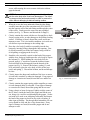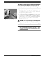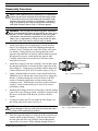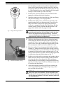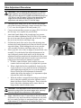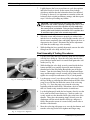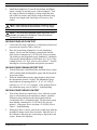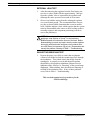
1
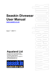
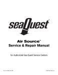
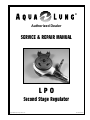
®
Authorized Dealer
SERVICE & REPAIR MANUAL
LPO
Second Stage Regulator
Copyright ©2000 Aqua Lung America, Inc.
Doc. No. XXXX-XX
Contents
Introduction .................................................................................................... 1
Warnings, Cautions, & Notes ........................................................................................... 1
Scheduled Service ........................................................................................................... 1
General Guidelines ........................................................................................................... 1
Initial Inspection Procedure .......................................................................... 2
External Inspection ........................................................................................................... 2
Pressure Test .................................................................................................................... 2
Disassembly Procedures ............................................................................... 3
Reassembly Procedures................................................................................ 6
Valve Adjustment Procedures....................................................................... 8
Final Assembly & Testing Procedures ......................................................... 9
Second Stage Air Flow Test ............................................................................................ 10
Second Stage Opening Effort Test ................................................................................. 10
Second Stage Purge Flow Test ...................................................................................... 10
External Leak Test .......................................................................................................... 11
Subjective Breathing Test ............................................................................................... 11
Table 1 – Troubleshooting Guide ................................................................ 12
Table 3 – Standard Parts Replacement Schedule ..................................... 13
Table 2 – Recommended Tool List .............................................................. 13
Table 5 – Test Bench Specifications ........................................................... 14
Table 4 – Torque Specifications .................................................................. 14
Procedure A – Cleaning & Lubrication....................................................... 15
Table A – Recommended Lubricants & Cleaners ...................................... 16
Schematic Drawing – LPO Second Stage .................................................. 17
Doc. #XXXX-XX
Service & Repair Manual - LPO Second Stage Regulator
Introduction
GENERAL GUIDELINES
This manual provides factory prescribed procedures for the service and repair of the LPO second
stage regulator. It is not intended to be used as an
instructional manual for untrained personnel. The
procedures outlined within this manual are to be
performed only by personnel who have received
factory authorized training through a factory sponsored Aqua Lung Service & Repair Seminar.
If you do not completely understand all of the
procedures outlined in this manual, contact Aqua
Lung to speak directly with a Technical Advisor
before proceeding any further.
1.
2.
Warnings, Cautions, & Notes
Pay special attention to information provided in
warnings, cautions, and notes that are accompanied
by one of these symbols:
A WARNING indicates a procedure or situation
that may result in serious injury or death if
instructions are not followed correctly.
3.
4.
A CAUTION indicates any situation or technique that will result in potential damage to the
product, or render the product unsafe if instructions are not followed correctly.
A NOTE is used to emphasize important
points, tips, and reminders.
Scheduled Service
5.
Regulators should be given the same care and
maintenance as life support equipment. It is therefore important to perform scheduled overhaul service
for the LPO, complete with first stage, according to
the procedures outlined in this manual; at least once 6.
a year with normal or infrequent use.
NOTE: A unit that receives heavy or frequent
use, such as in rental, instruction, or commer7.
cial applications, should be serviced at least
twice each year - or more often - depending on
the conditions of use and the manner in which
it is maintained. (Refer to the care and maintenance procedures outlined in the Regulator
Owner’s Manual.)
In order to correctly perform the procedures
outlined in this manual, it is important to follow
each step exactly in the order given. Read over
the entire manual to become familiar with all
procedures before attempting to disassemble or
service the LPO second stage, and to learn
which specialty tools and replacement parts will
be required. Keep the manual open beside you
for reference while performing each procedure.
Do not rely on memory.
All service and repair should be carried out in a
work area specifically set up and equipped for
the task. Adequate lighting, cleanliness, and
easy access to all required tools are essential for
maintaining a professional repair facility.
Before beginning any disassembly, it is important to first perform the Initial Inspection procedure, and refer to Table 1 - Troubleshooting to
determine the possible cause of any symptoms
which may be present.
As each individual regulator is disassembled,
reusable components should be segregated to
prevent them from mixing with non-reusable
parts or parts from other regulators. Delicate
parts, and those which contain critical sealing
surfaces, must be protected and isolated from
other parts to prevent damage during the cleaning procedure.
Use only genuine Aqua Lung parts purchased
directly from Aqua Lung when servicing any
Aqua Lung product. Substitution with another
manufacturer’s parts constitutes an after-market
modification of the product, and renders the
original warranty null and void.
Do not attempt to reuse mandatory replacement
parts under any circumstances, regardless of the
amount of use the product has received since it
was manufactured or last serviced.
When reassembling, it is important to follow
every torque specification prescribed in this
manual, using a calibrated torque wrench. Most
parts are made of either marine brass or plastic,
and can be permanently damaged by undue
stress caused by overtightening.
LPO Second Stage Service & Repair Manual
2
Initial Inspection Procedure
EXTERNAL INSPECTION
1. Visually inspect the sintered filter to check for any signs that
contaminants may have entered the system, such as moisture,
rust, aluminum oxide, or charcoal.
NOTE: A green discoloration positively indicates that moisture has entered the regulator, and internal corrosion is
therefore likely to be found in the first stage. A white or rust
colored residue usually indicates that the regulator has been
used with a corroded aluminum or steel cylinder. Advise the
customer of the proper methods for maintaining the regulator, and the possible need to obtain service for their cylinder.
2.
Slide back the hose protector(s) to inspect the condition of the
LP hose at its fittings and along its length. Check closely for
any signs of blistering or abrasion, or corrosion of the fittings.
3.
Inspect the condition of the mouthpiece to check for torn bite
tabs, holes, or deterioration.
PRESSURE TEST
1.
Prior to performing any disassembly, ensure that the second
stage is connected to a first stage with a stable intermediate
pressure of 135-140 psi, with no open ports or hoses.
2.
Listen closely to check for any signs of leakage from the
second stage. If necessary, immerse the second stage in water
to locate the source of any leakage found and refer to Table 1
- Troubleshooting to determine its possible cause.
CAUTION: If the second stage freeflows uncontrollably,
immediately shut the cylinder valve and proceed directly to
the Disassembly Procedure. Do not attempt to further
inspect the regulator while pressurized.
3.
Depress the purge button to determine whether sufficient
airflow is provided to clear the second stage of water. Immediately after releasing the purge button, listen closely to
ensure that no air continues to flow from the second stage.
4.
Turn the cylinder valve shut and depress the second stage
purge button to depressurize the regulator before proceeding
to the following Disassembly Procedure.
© 2000 Aqua Lung America, Inc.
LPO Second Stage Service & Repair Manual
3
Disassembly Procedures
NOTE: Before performing any disassembly, refer to Table 4,
which references all mandatory replacement parts. These
parts must be replaced with new, and must not be reused
under any circumstances - regardless of the age of the
regulator or how much use it has received since it was last
serviced.
CAUTION: To prevent damage to critical sealing surfaces,
use only a plastic or brass O-ring removal tool (P/N 9440-22)
when removing O-rings. Once an O-ring sealing surface has
been damaged, the part must be replaced with new in order
to prevent the possibility of leakage. DO NOT use a dental
pick, or any other type of steel instrument.
1.
While holding the inlet fitting(19) of the second stage secure
with a 19mm open end wrench, apply a 17mm (n") openend wrench to the female fitting of the LP hose(23). Turn the
fitting counter-clockwise to loosen and remove the hose from
the second stage. Remove the O-rings(22&24) from the hose
and discard. Set the hose aside.
2.
Carefully snip the plastic mouthpiece clamp(14) and remove
the mouthpiece(13) from the box bottom(15). Inspect the
mouthpiece to ensure it is free of any tears or cuts that may
cause leakage of water into the second stage or other discomfort. Discard the mouthpiece or set it aside to be reused,
depending on its condition.
3.
While holding the second stage secure, firmly grasp the color
ring(2) which holds the purge cover(1), and turn it counterclockwise to loosen and remove from the box bottom.
4.
While holding the color ring with both hands, press inward
against the top of the purge cover to remove it from the color
ring. Closely examine the color ring for any signs of thread
damage, and inspect the purge cover to check for any signs of
deterioration, distortion, or other damage. Replace with new
if any damage is found, or set these parts aside if they are in
reusable condition.
5.
Lift out the diaphragm(4) with retaining ring(3) and separate
these items to closely inspect the diaphragm for any signs of
tears, deterioration, or other damage. If deterioration or
damage is found, discard the diaphragm and do not attempt to
reuse.
6.
While holding the box bottom secure, apply a 19mm open
end wrench to the inlet fitting(19). Hold the lever(10) depressed, and carefully turn the fitting counter-clockwise to
loosen and remove. Remove and discard the O-ring(18).
7.
Apply a medium blade screwdriver to the slotted head of the
crown(20) inside the inlet fitting, and hold the inlet fitting
© 2000 Aqua Lung America, Inc.
LPO Second Stage Service & Repair Manual
4
secure while turning the crown counter-clockwise to disengage the threads.
NOTE: Because the crown is O-ring sealed, it will not freely
exit the valve body after it has been disengaged. The following step must be performed correctly in order to remove the
crown without damaging its delicate sealing surface.
8.
When the crown has been unthreaded from the inlet fitting,
carefully insert the pin of the extraction tool (P/N 1094-36)
into the opposite end of the inlet fitting and through the center
of the crown. Gently press the crown out onto a padded
surface (see Fig. 1). Remove and discard the O-ring(21).
9.
Closely examine the crown with the use of magnifier to check
for any scoring, nicks, or other damage to the polished sealing
surface. If damage is found, discard the crown, and do not
attempt to reuse. If it is in reusable condition, set it aside on a
soft surface to prevent damage to the sealing edge.
Fig. 1 – Crown Removal
10. Press the valve body(9) with lever assembly into the box
bottom by inserting a finger through the inlet opening. Gently lift the assembly out of the box bottom, being careful to
avoid pulling or tugging on the lever(10).
11. Stand the valve assembly vertical on the head of the poppet,
with the lever facing up, and depress the valve body to expose
the locknut(12). While holding the valve body fully depressed, apply a 4" nut driver to turn the locknut counterclockwise until it has disengaged from the threads of the
poppet (see Fig. 2). Remove the locknut, washer(11), and
lever, and slowly relax the valve body to lift it off the poppet(6) and spring(7). Discard the locknut, and do not attempt
to reuse.
12. Closely inspect the shape and condition of the lever to ensure
it is not bent, corroded, or otherwise damaged. If any signs of
damage or corrosion are found, discard the lever and do not
reuse.
13. Closely examine the poppet spring with a magnifier to ensure
it is not damaged (bent) or corroded. If any signs of damage
or corrosion are found, discard the spring and do not reuse.
14. Using a plastic or brass O-ring tool, lightly stick the center of
the LP seat(5) inside the head of the poppet and lift the seat
out, being very careful to avoid damaging the poppet. Set the
seat aside to be used as an aid during reassembly, and inspect
the head of the poppet to check for any nicks, scratches, or
other signs of damage. The through-hole beneath the LP seat
cavity should be clear and free of any obstructions. If any
signs of damage are found, discard the poppet and do not
attempt to reuse.
© 2000 Aqua Lung America, Inc.
Fig. 2 – Disassembly of Valve
LPO Second Stage Service & Repair Manual
5
NOTE: The used LP seat is an essential aid to the reassembly procedure for the valve body. Do not discard the seat
until the reassembly and final adjustment procedures have
both been performed, and the regulator is functioning satisfactorily.
15. Place the handle of the extraction tool directly over the poppet
bearing(8) in the top center of the valve body, and press
downward until the poppet bearing has dropped out. Discard
the poppet bearing, and do not reuse.
16. To remove the exhaust valve diaphragms(16), it is not necessary to remove the exhaust cover(17). Instead, use a pair of
needle nose pliers to pull each of the diaphragms through the
grill of the exhaust cover (see Fig. 3). Discard both diaphragms, and do not reuse.
Fig. 3 – Removing Exhaust Diaphragms
CAUTION: Aqua Lung recommends that the exhaust cover
should not be removed unless it appears to be damaged and
requires replacement. If removal and replacement is necessary, proceed with caution, being careful to avoid damaging
the box bottom.
This concludes the disassembly of the LPO second
stage. Refer directly to Procedure A and Table A, titled
Cleaning & Lubrication, before proceeding to the Reassembly Procedures.
© 2000 Aqua Lung America, Inc.
LPO Second Stage Service & Repair Manual
6
Reassembly Procedures
NOTE: Before performing any reassembly, it is important to
inspect all parts, both new and those that are being reused,
to ensure that every part and component is perfectly clean
and free of any dust, corrosion, or blemishes. Check all Orings to ensure they are clean and supple before dressing
with either Christo-Lube® or Dow 111 silicone grease.
WARNING: Use only genuine Aqua Lung parts, subassemblies, and components whenever assembling any Aqua Lung
product. DO NOT attempt to substitute an Aqua Lung part
with another manufacturer’s, regardless of any similarity in
shape, size, or appearance. Doing so may render the product unsafe, and could result in serious injury or death.
1.
Install each exhaust valve diaphragm(16) into the box bottom(15) by feeding the stem of the diaphragm through the
exhaust cover(17) and into the center hole of the valve in the
box bottom. Gently pull the stem through the hole on the
opposite side inside the box bottom, until the barb has passed
through and is securely seated against the opposite side.
Carefully snip off the excess material of each stem with a
small pair of scissors.
2.
Install the O-ring(21) onto the crown(20), and carefully insert
the threaded end of the crown into the hose connection of the
inlet fitting(19). Gently press it in further with the blunt end
of the extraction tool (P/N 1094-36) until it stops (see Fig. 4).
3.
Apply a medium blade screwdriver to the slotted head of the
adjustable crown, and turn the crown clockwise to engage the
threads. Continue turning the crown clockwise to the full
extent of its thread engagement, and stop turning when
resistance is felt. Then turn the crown out counter-clockwise
exactly 22 turns counterclockwise to arrive at its correct
preliminary setting.
4.
Stand the inlet fitting vertical on a flat surface with the sealing
edge of the crown facing up inside. Install the O-ring(18) into
the groove at the base of the threads, just above the hex
feature.
5.
Lay the previously used LP seat inside the inlet fitting, over
the sealing edge of the crown (see Fig. 5).
NOTE: It is essential to use a spare LP seat in order to
prevent damage to the new seat while performing the following steps of the reassembly procedure.
6.
Place the poppet bearing(8) over the pin of the extraction tool
with the square feature facing up. Guide the pin of the tool
into the open end of the valve body(9) and out through the
square hole in its center. While sighting through the top of
© 2000 Aqua Lung America, Inc.
Fig. 4 – Crown Installation
Fig. 5 – Using Old LP Seat as Spacer
LPO Second Stage Service & Repair Manual
7
the valve body, rotate the tool as needed to align the square
feature of the poppet bearing with the square hole, and press
the tool upward to seat the bearing securely in place (see Fig.
6). When finished, check to ensure that the top of the poppet
bearing is flush with the top of the valve body.
Fig. 6 – Poppet Bearing Installation
7.
Press the new LP seat(5) into the cavity in the head of the
poppet(6), with the smooth side facing out.
8.
Stand the poppet on its head inside the top of the inlet fitting,
and place the spring(7) over the poppet shaft.
9.
Hold the inlet fitting secure, and mate the valve body with
poppet bearing down over the poppet shaft. Press the valve
body downward to compress the spring while turning it
clockwise to engage the threads of the inlet fitting, and then
continue turning it slowly until the threaded portion of the
poppet shaft stands outside the poppet bearing.
CAUTION: If resistance is felt, immediately stop and unscrew the valve body from the inlet fitting to check the alignment of the poppet shaft and poppet bearing. Excessive
force and misalignment will otherwise result in damage to the
poppet bearing, requiring its replacement.
10. While the inlet fitting and valve body are laying horizontal,
rotate both parts until the outlet ports of the valve body face
towards 6 O’clock. Lay the arms of the lever(10) inside the
groove of the valve body, straddling the poppet shaft, so that
the curved portion of the lever faces towards 12 O’clock.
1-2 threads
Fig. 7 – Locknut Preliminary Setting
11. Place the washer(11) over the poppet shaft, followed by the
locknut(12), with the flat side facing down. Being careful to
avoid disturbing the lever, turn the locknut clockwise by hand
to engage the threads of the poppet, and then apply a 4" nut
driver to turn it further; only until 1 thread of the poppet shaft
is visible above the top of the locknut (see Fig. 7).
12. Hold the valve body and lever stationary and upright with one
hand, and slowly unscrew the inlet fitting counter-clockwise
to loosen and remove from beneath it, while watching to
ensure that the lever rises slightly as the poppet shaft retracts
into the valve body. Remove and discard the previously used
LP seat from the inlet fitting.
13. After removing the previously used LP seat, reconnect the
valve body and inlet fitting and tighten finger snug so that
they are flush with each other.
NOTE: This concludes the preliminary reassembly procedures of the main valve assembly. Do not proceed to reassemble the LPO second stage any further until first following
the adjustment procedures for the valve assembly outlined in
the following section.
© 2000 Aqua Lung America, Inc.
LPO Second Stage Service & Repair Manual
8
Valve Adjustment Procedures
CAUTION: Prior to adjusting and testing the LPO second
stage regulator, the accompanying first stage must be correctly serviced, adjusted to a stable intermediate pressure of
135-140 psi, and fully tested. Refer to the appropriate first
stage service manual before attempting to perform the
adjustment and testing of the LPO second stage.
1.
2.
3.
4.
5.
Thread the male fitting of the IP hose into the low pressure
port of the first stage, and apply a torque wrench with 17mm
(n") crow-foot to tighten to 40 inch-pounds (±2).
Connect an intermediate pressure test gauge (P/N 1116-10) to
the first stage via a separate low pressure hose.
Attach the female fitting of the second stage low pressure
hose to the Inline Adjustment Tool (P/N 1001-95) by mating
the swivel nut onto the male threaded end of the tool. Turn
the swivel nut clockwise until finger snug.
Pull back the knob of the tool to retract the adjusting stem,
and mate the female threaded end of the tool onto the second
stage inlet fitting. While holding the tool secure, turn the
valve assembly clockwise until finger snug (see Fig. 8).
Slowly open the valve of the air supply to pressurize the valve
assembly. Press the knob of the inline adjustment tool inward, and gently turn the knob until it can be felt that the
adjustment stem has mated into the slotted head of the crown.
Continue to hold the knob inward, in order to prevent it from
being pressed outward by the internal air pressure.
a. If airflow cannot be heard, slowly turn the crown out
counter-clockwise only until a very slight leak is present.
b. When a slight leak has been established, slowly turn the
crown clockwise in very small increments of adjustment
while lightly depressing the lever to cycle the regulator.
Pause to listen after each adjustment to determine
whether the airflow has stopped. It is important to adjust
only until the airflow has stopped.
c. When the airflow is stopped and no leakage can be heard
after cycling the regulator, proceed to adjust the crown
further clockwise exactly 180 degrees. Then, release the
knob of the inline adjustment tool to ensure that it no
longer makes contact with the crown.
Fig. 8 – Inline Tool Connection
1–2 mm freeplay while pressurized
CAUTION: Over-adjustment of the orifice crown will cause
excessive spring load in the second stage valve, and may
severely degrade the performance of the regulator.
6.
Apply a hand driver with 4" tapered hex to turn the locknut
clockwise in very small increments of adjustment; only until
the lever stands just below its maximum height; with a very
slight amount (1–2 millimeters) of freeplay (see Fig. 9).
© 2000 Aqua Lung America, Inc.
Fig. 9 – Lever Height Adjustment
LPO Second Stage Service & Repair Manual
7.
9
Lightly depress the lever several times to cycle the regulator
and listen closely to check for the return of any leakage,
which may indicate that the locknut has been over-adjusted.
If leakage is detected, it is important to return the crown and
locknut to their original preliminary settings, and then repeat
steps 5-6 before proceeding any further.
CAUTION: Over-adjustment of the locknut will retract the
poppet from the crown, resulting in leakage past the LP seat.
Do not attempt to correct this condition by only readjusting
the crown further in clockwise. Doing so may increase the
opening effort and inhalation resistance of the regulator due
to excessive spring load in the second stage valve.
8.
When the crown and locknut are properly set with no leaks
and the lever is standing at its correct height, turn the valve of
the air source completely shut, and lightly depress the lever to
depressurize the system. Disconnect the in-line adjustment
tool from the second stage valve assembly.
9.
While holding the lever partially depressed, unscrew the inlet
fitting from the valve body and set it aside.
Final Assembly & Testing Procedures
Fig. 10 – Installing Valve Assembly
1.
Lay the valve body and lever assembly inside the box bottom
with the lever facing up. Mate the valve body into the inlet
port of the box bottom until it is seated flush against the wall
inside (see Fig. 10).
2.
While holding the valve body securely seated inside the box
bottom and the lever partially depressed, mate the shorter
threaded end of the inlet fitting through the port of the box
bottom. Turn the inlet fitting clockwise by hand until finger
snug, and then apply a torque wrench with a 19mm socket to
tighten it to a torque measurement of 50 (±5) inch-pounds.
3.
Lay the purge cover(1) over the top of the color ring(2) with
the logo facing up, and align the indexed tab on the side of the
purge cover with the slot inside the center of the color ring
(see Fig. 11). Press the purge cover into the color ring,
beginning with the indexed tab. When done, check to ensure
that it is seated evenly around its entire circumference.
4.
Lay the diaphragm(4) inside the box bottom, directly over the
lever, with its raised center facing up. Check to ensure it is
evenly seated over the shoulder on all sides at the base of the
threads. Then, place the retaining ring(3) directly over the
diaphragm with the raised shoulder facing up, and press it
firmly downward to ensure it is seated evenly on all sides at
the base of the threads.
5.
Mate the color ring with purge cover over the box bottom, and
turn the color ring clockwise to tighten until finger snug.
Fig. 11 – Purge Cover Alignment
© 2000 Aqua Lung America, Inc.
LPO Second Stage Service & Repair Manual
10
6.
Install the mouthpiece(13) onto the box bottom, and lightly
fasten a clamp(14) onto the groove of the mouthpiece. Turn
the clamp so that the locking tab is facing toward the inlet
side of the box bottom, and pull the clamp sufficiently snug.
Snip the extra length with a small pair of scissors or wire
cutters.
NOTE: Before performing the following procedure, refer to
Table 5, titled Test Bench Specifications - LPO 2nd Stage.
NOTE: If an accurately calibrated airflow test bench is not
available, proceed to the Subjective Tuning Procedures
provided on the following page.
SECOND STAGE AIR FLOW TEST
1.
Connect the first stage regulator to a calibrated test bench and
pressurize the system to 3000 (±100) psi.
2.
Place the second stage mouthpiece over the mouthpiece
adapter. Slowly turn the flowmeter control knob until the
flow reaches a minimum of 15 SCFM (425 liters per minute).
The reading on the Magnahelic gauge (inhalation / exhalation
effort gauge) should indicate no more than +6.O" H2O. If the
reading exceeds +6.0" H2O, refer to refer to Table 1 - Troubleshooting for corrective guidelines and specific procedures.
SECOND STAGE OPENING EFFORT TEST
1.
Turn the flowmeter control knob shut, and then slowly reopen
while watching both the Magnahelic gauge and the intermediate pressure gauge.
2.
When the intermediate pressure gauge begins to drop below
the intermediate pressure “lockup,” the Magnahelic gauge
should indicate an opening effort of +.8" to +1.4" of H2O
(primary) or +1.2" to +1.8" (octopus). If the opening effort is
not within this range, refer to Table 1 - Troubleshooting.
SECOND STAGE PURGE FLOW TEST
1.
Turn off the flowmeter control knob. Next, while the second
stage is still mounted on the mouthpiece adapter, watch the
flowmeter gauge and depress the purge button until the
second stage valve is completely open. The flowmeter gauge
must indicate a minimum of +5.0 SCFM (142 Liters per
minute.). If the purge flow is less than +5.0 SCFM, refer to
Table 1 - Troubleshooting.
2.
When purge flow is correct, remove the second-stage from the
mouthpiece adapter on the flow test bench. Shut the valve of
the test bench, and purge the second stage to depressurize the
system. Remove the regulator.
© 2000 Aqua Lung America, Inc.
LPO Second Stage Service & Repair Manual
11
EXTERNAL LEAK TEST
1.
After disconnecting the regulator from the flow bench, connect it to a scuba cylinder filled to approximately 3,000 psi.
Open the cylinder valve to repressurize the regulator, and
submerge the entire system in a test tank of clean water.
2.
Observe any bubbles arising from the submerged regulator
over a one minute period. The recommended time is necessary due to slower bubble formation that occurs in smaller
leaks. Bubbles indicate a leak, which requires that the system
must be disassembled at the source to check sealing surfaces,
assembly sequence and component positioning in order to
correct the problem(s).
NOTE: Extremely small leaks may be better detected by
applying a soap solution or Snoop™ to the leak area.
Bubble streams will indicate the source of the leak. Before
disassembling to correct any leaks, rinse the entire regulator
thoroughly with fresh water and blow out all residual moisture with filtered, low-pressure (50 psi) air. Disassemble and
remedy the problem, referring to Table 1 - Troubleshooting.
SUBJECTIVE BREATHING TEST
1.
Depress the purge cover fully to ensure that an adequate
volume of air needed to clear the second stage flows through
the mouthpiece. Then, inhale slowly but deeply from the
mouthpiece. A properly serviced and adjusted regulator
should deliver air upon deep inhalation without excessive
inhalation effort, freeflow, or “fluttering” of the second-stage
diaphragm. When exhaling, there should be no fluttering or
sticking of the exhalation valve. If any of these problems
occur, refer to Table 1 - Troubleshooting.
This concludes annual service procedures for the
LPO Second Stage.
© 2000 Aqua Lung America, Inc.
LPO Second Stage Service & Repair Manual
12
Table 1
Troubleshooting Guide – LPO Second Stage
SYMPTOM
Leakage or freeflow from
second stage
Low purge or excessive work
of breathing (full cylinder)
External air leakage
Water entering second-stage
POSSIBLE CAUSE
TREATMENT
1. High first-stage intermediate pressure.
(should be 135-140 psi)
1. Refer to first-stage Troubleshooting Guide.
2. LP seat(5) damaged or worn.
2. Replace LP seat.
3. Crown(20) and/or locknut(12) adjusted
incorrectly, lever set too high.
3. Reset crown and locknut to
preliminary settings, and repeat
Adjustment Procedures.
4. Crown(20) sealing surface damaged.
4. Replace crown.
5. Poppet spring(7) damaged.
5. Replace poppet spring.
1. Low intermediate pressure.
(should be 135-140 psi)
1. Refer to first-stage Troubleshooting Guide.
2. Crown(20) and/or locknut(12) adjusted
incorrectly, lever set too low.
2. Reset crown and locknut to
preliminary settings, and repeat
Adjustment Procedures.
3. Intermediate pressure hose(23)
clogged or obstructed.
3. Clean or replace hose.
1. Intermediate pressure hose(23) loose.
(Immersion Test)
1. Tighten to 40 inch-lbs at female
second-stage fitting.
2. Crown O-ring(21) damaged.
2. Disassemble and replace O-ring.
3. Box bottom(15) damaged.
3. Disassemble and replace box
bottom.
1. Hole in mouthpiece(13).
1. Replace mouthpiece.
2. Demand diaphragm(4) damaged.
2. Replace demand diaphragm.
3. Exhaust diaphragm(16) damaged.
3. Replace exhaust diaphragm(s).
4. Diaphragm(4) improperly seated
between box bottom(15) and
retaining ring(3).
4. Remove color ring(2) and properly reassemble sealing ring with
diaphragm . (Check for distortion.)
5. Box bottom(15) damaged.
(Check exhaust valve sealing surface.)
5. Disassemble and replace box
bottom.
6. Valve insert O-ring(18) damaged.
6. Disassemble and replace O-ring.
CAUTION: Recommended treatments which require disassembly of the regulator
must be performed during a complete overhaul, according to the prescribed procedures for scheduled, annual service. Do not attempt to perform partial service.
NOTE: This is a partial list of possible problems and recommended treatments. For
more information, refer to the second-stage troubleshooting guide, or contact the
Repair Department for assistance with problems not described here.
© 2000 Aqua Lung America, Inc.
LPO Second Stage Service & Repair Manual
13
Table 2
Recommended Tool List
PART NO.
1116-10
DESCRIPTION
APPLICATION
I.P. test gauge
Intermediate pressure testing
0-120 inch-lbs torque wrench
Inlet & hose fittings installation
O-ring tools
O-ring removal & installation
N/A
Magnifier w/ illumination
Sealing surface inspection
N/A
Ultrasonic cleaner
Brass & stainless steel parts cleaning
N/A
Medium blade screwdriver
Crown removal/ installation
N/A
17mm (n") wrench & crow foot
IP hose fitting
N/A
4" nut driver
Valve disassembly/ assembly/ adjustment
1094-36
Seat extraction/installation tool
Crown removal & installation
1001-95
In-line adjustment tool
Final adjustment & tuning
N/A
9440-22
Table 3
Standard Parts Replacement Schedule
PART NUMBER
DESCRIPTION
KEY NUMBER
QTY
1025-10
Locknut
12
1
1041-34
Poppet Bearing
8
1
1067-38
LP Seat
5
1
8200-11
O-ring
24
1
8200-10
O-ring
21 & 22
2
8200-15
O-ring
18
1
1049-13
Clamp
14
1
1078-22
Exhaust Diaphragm
16
2
© 2000 Aqua Lung America, Inc.
LPO Second Stage Service & Repair Manual
14
Table 4
Torque Specifications
PART NUMBER
DESCRIPTION / KEY NUMBER
TORQUE
0900-39
LP Hose Female Fitting / 23
40 (±3) inch-lbs
1041-06
Inlet Fitting/ 19
50 (±5) inch-lbs
Table 5
Test Bench Specifications
TEST
CONDITION
ACCEPTABLE RANGE
Leak test
Inlet 2,500-3,000 (±100) psi
None
Intermediate pressure
Inlet 2,500-3,000 (±100) psi
135-140 psi
Intermediate pressure creep Inlet 2,500-3,000 (±100) psi
5 psi max between 5 to 15 seconds
after cycling regulator (purge)
Opening effort
Inlet 2,500-3,000 (±100) psi,
intermediate pressure 135-140 psi
+.8 to +1.4 inch H20 (primary)
+.8 to +1.8 inch H20 (octopus)
Flow effort
Intermediate pressure 135-140 psi
at 15 SCFM
+6 inches H20 (maximum)
Purge flow
Intermediate pressure 135-140 psi
5.0 SCFM flow rate (minimum)
© 2000 Aqua Lung America, Inc.
LPO Second Stage Service & Repair Manual
15
Procedure A
Cleaning & Lubrication
(All Aqua Lung Regulators)
1. Acid Bath - Aqua Lung strongly recommends ChromeSafe™ regulator cleaner (P/N 0201-05) for cleaning all reusable brass and stainless steel parts. ChromeSafe™ is a specially formulated cleaner that does
not harm rubber or Teflon parts, yet effectively removes silicone grease, corrosion, and grime from metal
parts, leaving only a brilliant shine. For best results, soak parts in an ultrasonic cleaner for 5 to 15
minutes, unless the chrome finish is chipped or flaking. Parts with damage to their chrome finish should
be cleaned separately outside the ultrasonic cleaner to avoid agitation. Be certain to isolate more delicate
parts, such as orifice cones, to prevent damage to sealing surfaces.
CAUTION: Harsh acids, such as muriatic acid, may cause damage to parts and must be strictly
avoided. White vinegar, although less effective, is one suitable substitute for ChromeSafe™.
CAUTION: Ultrasonic cleaning times in excess of 15 minutes may damage the chrome finish of certain
parts. Be certain to use a timer, and do not leave parts unattended while cleaning.
NOTE: Although ChromeSafe™ contains a degreasing agent, cleaning heavily greased parts in
ChromeSafe™ will shorten the effective life of the solution, and require it to be replaced on a more
frequent basis. Heavily greased parts may be degreased in a solution of warm water and mild dish
detergent prior to being placed in the acid bath.
2. Fresh Water Rinse - If tap water is extremely “hard,” distilled water may be used to prevent any mineral
residue. Remove parts from the acid bath and place directly into this rinse. Agitate lightly, and allow to
soak for 5-10 minutes. Remove and blow dry with low pressure (25 psi) filtered air, and inspect closely
to ensure proper cleaning and like-new condition.
ANODIZED ALUMINUM, PLASTIC & RUBBER PARTS
Anodized aluminum parts and parts made of plastic or rubber, such as box bottoms, box tops, dust caps,
etc., may be soaked and cleaned in a solution of warm water mixed with mild dish soap. Use only a soft
nylon toothbrush to scrub away any deposits. Thoroughly blow dry, using low pressure filtered air.
HOSES
If buildup of corrosion is severe, it is permissible to soak only the hose fittings in ChromeSafe™ cleaner
as needed, and not allow any solution to enter the hose. Rinse in fresh water and allow to dry with the
cleaned ends hanging down. Blow filtered air through them prior to installing onto the regulator.
LUBRICATION AND DRESSING
All O-rings should be lubricated with either Christo-Lube® (preferred for high pressure systems) or Dow
Corning® 111 food grade silicone grease . Dress the O-rings with a very light film of grease, and remove
any visible excess by running the O-ring between thumb and forefinger. Avoid applying excessive
amounts of silicone grease, as this will attract particulate matter that may cause damage to the O-ring.
Hoses and other black rubber parts may be dressed and preserved using a clean cloth impregnated with a
pump silicone milk.
CAUTION: Aerosol spray silicone must be strictly avoided. Do not attempt to use as a substitute for
silicone grease.
CAUTION: Do not apply any form of silicone lubricant to silicone rubber parts, as this will cause them
to deteriorate prematurely.
© 2000 Aqua Lung America, Inc.
LPO Second Stage Service & Repair Manual
16
Table A
Recommended Lubricants & Cleaners
(All Aqua Lung Regulators)
LUBRICANT / CLEANER
APPLICATION
SOURCE
Christo-Lube®
All O-rings seals; cylinder valve threads
(preferred for high pressure DIN systems)
Lubrication Technologies
310 Morton Street
Jackson, OH 45640
(614) 286-2644
Dow Corning® 111
(pure silicone grease)
All O-ring seals
Dow Corning Corp.
P.O. Box 1767-T
Midland, MI 48640
800-248-2481
CAUTION: Silicone rubber requires no lubrication or preservative treatment. DO NOT
apply silicone grease or spray to silicone rubber parts. Doing so will cause a chemical
breakdown and premature deterioration of the material.
Silicone Pump™
(non-aerosol silicone milk spray)
General preservative/conditioner for
hoses, instrument console boots, etc.
McNett Corp.
P.O. Box 996
Bellingham, WA 98227
800-221-7325
CAUTION: Aerosol spray silicone should be avoided because (1) common aerosol
propellants may attack plastic and rubber parts, and (2) because only a slight amount
of silicone remains after the solvent evaporates, and provides no lasting benefit.
Anti-Seize Lubricant #80208
M.A.S. cylinder adapter - female threads
Micra ADJ adjustment screw
Permatex Industrial Corp.
705 N. Mountain Rd.
Newington, CT 06111
(860) 520-5000
ChromeSafe™
(ultrasonic cleaning solution)
Degreaser and acid bath for reusable
stainless steel and brass parts.
Aqua Lung P/N 0201-05
(1 quart)
Oakite #31
Acid bath for reusable stainless
steel and brass parts.
Oakite Products, Inc.
50 Valley Road
Berkeley Heights, NJ 07922
White distilled vinegar
(100 gr.)
Acid bath for reusable stainless
steel and brass parts.
"Household" grade
CAUTION: DO NOT use muriatic acid for the cleaning of any parts. Muriatic acid,
even when strongly diluted, can harm chrome plating, and may leave a residue that is
harmful to O-ring seals and other parts.
Liquid dishwashing detergent
(diluted with warm water)
Degreaser for brass and stainless steel parts,
general cleaning solution for plastic, rubber,
and anodized aluminum parts.
"Household" grade
Snoop™
Leak testing
Nupro Company
400 E. 345th St.
Willoughby, OH 44094
440-951-7100
© 2000 Aqua Lung America, Inc.
LPO Second Stage Service & Repair Manual
17
LPO Second Stage
1
2
3
4
5
6
7
8
10
13
9
12
20
21
19
11
18
14
23
22
15
16
16
17
24
25
Key # Part #
----- 9000-11
1 ----- 1009-04
2 ----- 1009-06
3 ----- 1009-09
4 ----- 1001-81
5 ----- 1067-38
6 ----- 1041-22
7 ----- 1041-27
8 ----- 1041-34
9 ----- 1009-45
10 ---- 1009-23
11 ---- 1041-29
12 ---- 1025-10
13 ---- 1058-31
Description
Overhaul Parts Kit
Purge Cover
Color Ring
Retaining Ring
Diaphragm
LP Seat
Poppet
Spring
Poppet Bearing
Valve Body
Lever
Washer
Locknut
Mouthpiece
Key # Part #
14 ---- 1049-13
15 ---- 1009-03
16 ---- 1009-22
17 ---- 1009-07
18 ---- 8200-15
19 ---- 1041-06
20 ---- 1078-05
21 ---- 8200-10
22 ---- 8200-10
23 ---- 0900-39
24 ---- 8200-11
25 ---- 1009-24
Description
Clamp
Box Bottom
Exhaust Valve Diaphragm
Exhaust Cover
O-ring
Inlet Fitting
Adjustable Crown
O-ring
O-ring
LP Hose
O-ring
Hose Retaining Clip
Part numbers in BOLD ITALICS indicate standard overhaul
replacement part.
© 2000 Aqua Lung America, Inc.
2340 Cousteau Court
Vista, California 92083
Phone (760) 597-5000
Fax (760) 597-4900
www.aqualung.com