1
PUMP INSTALLATION
PUMP LOCATION
Bell & Gossett booster pumps should be installed where there
will be sufficient room for future inspection, maintenance and
service. It is highly recommended that service valves (shut-off)
also be installed on each side of circulator pumps to facilitate
servicing or replacing the pump without draining the system.
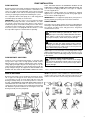
If it is required to lift the entire pump, do so with slings placed
around the pump assembly as shown below.
IMPORTANT: In closed systems, do not install and operate
Bell & Gossett pumps, 3D valves, suction diffusers, etc., without properly sized safety and control devices. Such devices
include the properly sized and located pressure relief valves,
compression tanks and pressure, temperature, and flow controls. If the system is not equipped with these devices, consult
the responsible engineer or architect before operating.
TION. THIS MAY RESULT IN UNWANTED STRESS IN THE
PUMP BODY, FLANGE CONNECTIONS AND/OR PIPING. The
code for pressure piping, ANSI B31.1, lists types of supports
for various applications.
Ordinary wire or band hangers are not adequate to maintain
alignment. It is very important to provide strong, rigid support
for the suction and discharge lines.
IMPORTANT: Do not support the pump by its power pack. To
function properly, the power pack must not be restrained.
PUMP FLANGES
New Bell & Gossett flange gaskets must be installed between
the flanges of the pump body and suction and discharge pipes.
The gaskets should be clean and grease-free; old gaskets
should never be reused.
WARNING: HOT WATER HAZARD
When disassembling a gasketed joint, always use a
new gasket upon reassembly. NEVER RE-USE OLD GASKETS. Failure to follow these instructions could result in
serious personal injury, death and/or property damage.
WARNING: HOT WATER HAZARD
Make sure that each flange gasket remains seated in
the flange groove during and after installation. Failure to follow these instructions could result in serious personal
injury, death and/or property damage.
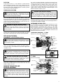
Apply torque in even increments to all (4) flange bolts using a
diagonal tightening pattern to a value of 96-132 in-lbs. (8-11 ft.
lbs.). Both the suction and discharge flanges must be torqued
in this manner.
PUMP SUPPORT AND PIPING
Install the suction and discharge flanges on the pipe ends
using Teflon ® * tape sealer or high quality thread sealant.
Minimize strain on the pump by supporting the suction and discharge piping with pipe hangers near the pump. Line up the
vertical and horizontal pipings so that the bolt-holes in both the
pump and pipe flanges are aligned. DO NOT ATTEMPT TO
SPRING THE SUCTION OR DISCHARGE LINES INTO POSI-
MODE OF DISCHARGE
Bell & Gossett Pumps can be installed to discharge up, down,
left or right. The oiling ports must always be in the twelve
o’clock position (on top) as shown below with the motor and
bearing assembly always in a horizontal position as shown to
the right. THE ARROW ON THE PUMP BODY MUST POINT IN
THE DIRECTION OF THE FLOW. If it becomes necessary to
change the mode of discharge, refer to B&G Instruction Manual
HS-105-SM for specific instructions in removing the motor and
bearing assembly from the pump body.
WARNING: WATER LEAKAGE HAZARD
To prevent leakage, make certain that the flange
bolts have been adequately torqued. Failure to follow these
instructions could result in serious personal injury and/or
property damage.
*Teflon® is a registered trademark of E.I. DuPont de Nemours and Company.
NOTE: The position of the conduit box is determined by the
model of the motor used and must be positioned on the
bottom or the side of the motor housing. As shown to the left.
3