1
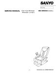
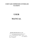
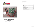
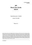
FILE No.
SERVICE MANUAL
MODEL
Power source
Power consumption
Rated time
Personal sensor course
Automatic course
Kneading rate
Massage chair
HEC-DR21 (TAIWAN)
HEC-DR21
PRODUCT CODE NO.
AC 110 V 60Hz
165 W
1 - 383 206 51 ( K )
1 - 383 206 52 ( H )
30 minutes
Recovery / Relax
Four (neck / shoulders, upper torso, lower back, legs)
Approx. 16,22,30 pulses/min. (3 speeds)
Tap rate
Tap range
Back stretch settings
Approx. 300,480,600 times/min. (3 positions)
Approx. 70,100,130mm (3 positions)
Approx. 70,100,130mm (3 positions)
Vertical motion rate
Approx. 30sec./up-and-down cycle
Massage sphere vertical reach
Approx. 635mm (straight line)
Reclining angle
Back: approx. 120-170 degrees, Leg: approx. 0-100 degrees
Leg massage
Rotating roller (Manual course: approx. 15 min., Automatic course: approx. 12 min.)
Roller rotation
Higher speed: 100 times/min., Lower speed: 70 times/min.
Timer
Approx. 13 min. (Automatic Sensor course)
Approx. 12 min. (Automatic course)
Approx. 15 min. (Manual course)
Dimensions (W x D x H)
Weight
Approx. 670 x 1,000 x 1,050 mm (When footrest is stored)
Approx. 670 x 1,550 x 550 mm (When footrest is in horizontal position)
Approx. 670 x 1,700 x 550 mm (When footrest is fully opened)
Approx. 55 kg
- 1-
REFERENCE NO. SM6510406-00
Block Diagrams
HEC-DR21 (TAIWAN)
Back rest massage unit
Remote control
Foot rest massage unit
Control unit
Body contour detection (coil)
Top end position detection of
back massage section (microswitch)
Body contour detection
Top end position detection
Rotation detection of massaging
motor (Hall IC IC-202)
Massaging pulse detection
Detection of massaging arm home
position (Hall IC IC-201)
Massaging home position detection
Rotation detection of tapping
motor (Hall IC IC-301)
SW for entering signals for instructing
actions and LED for displaying the status
Back rest massage unit
Tapping
motor
Tapping pulse detection
Remote control operation and display
Stiffness sensor section
Detection of perspiration rate
by electric resistance
Detection of number of
pulses by light
Skin temperature detection
by thermistor
Detection of rotation and rotating
direction of elevating motor
(Hall IC CI-401/402)
Control unit
Perspiration rate detection
Elevation
motor
Detection of number of pulses
Skin temperature detection
Reclining motor
(Back rest)
Detection of elevating motor rotation
Top and bottom reclining end
detection of backrest section
(microswitch)
Reclining (backrest) limit detection
Top and bottom reclining end
detection of footrest section
(microswitch)
Reclining (footrest) limit detection
Load detection of leg massaging
motor (CT1)
Massaging
motor
Reclining motor
(Foot rest)
Foot rest massage unit
Leg motor load detection
- 2-
Leg roller
motor
CNA801
- 3-
Condenser
(16 F)
Motor
(Elevation)
Switch
Switch
Motor
CNA701
15
CN603
Switch
Switch
Motor
CN601
CN401
CN402
CN251
Printed board
(Foot Rest)
CN252
CN253
Printed board
(UP/DOW Pulse)
CN403
CN404
Motor
(Leg Roller)
Reclining Motor(Back Rest)
CN602
Printed board
(Control)
Printed board
(Indication)
CNA702
12
CNA601
CN604
Reclining Motor(Leg Rest)
Sensor B
Printed board
(Sensor B)
CN951
Printed board
(Sensor A)
CN14
CN13
CN8
CN6
CN10
CN9
CN1
CN18
CN20
CN19
CN15
CN7
Printed board(Main)
CN4
CN3
CN2
CN12
CN5
CN11
CN301
Limit Switch
Printed board
(Pulse)
Reactor(Leg Roller)
Reactor
Reactor
Printed board
(Shape)
CN502
CN202
CN203
Printed board
(Relay)
CN201
Fuse (250V 4A)
Motor
Motor
CN503
CN501
Transfomer
Shape Sensor
Transfomer
Switch
Wiring Diagram
HEC-DR21 (TAIWAN)
Shape sensor
Printed board
(Pulse)
Limit switch
Switch(DOW)
Reclining motor (Leg rest)
Switch(UP)
Switch(DOW)
Switch(UP)
Reclining motor (Back rest)
Printed board (Shape)
Printed board
(Relay)
-4Motor
(Elevation)
Printed board
(UP/DOW pulse)
Condenser
Printed board (Main)
Printed board (Foot rest)
Transfomer
Fuse
Reclining motor (Back rest)
Motor (Leg roller)
Reactor
Switch
Reclining motor
(Back rest)
Motor (Massaging)
Reactor
Motor (Tapping)
Reactor
Circuit Diagram
HEC-DR21 (TAIWAN)
Printed board (Indication)
- 5Printed board
(Sensor B)
Sensor B
Printed board
(Sensor A)
Printed board (Control)
Circuit Diagram
HEC-DR21 (TAIWAN)
Operation of Stiffness
Detecting Sensor
HEC-DR21 (TAIWAN)
To the remote controller sensor section, three kinds of sensors (skin electric resistance,
photo sensor, thermistor) are assembled, and measure three kinds of physiological
amounts (perspiration, pulse, skin temperature).
When stiff portions are subject to massage stimulus of detection massage, changes are
observed in the perspiration rate, number of pulses, and skin temperature.
These three kinds of displacements are measured.
Perspiration
Pulse
Skin temperature
sensor section
If your body receives stimulus
and feels “stiffness,”
Use rollers for legs.
Use massaging
balls for neck/shoulder,
back, and waste.
Perspiration
increases.
Pulses
accelerate.
Skin temperature
lowers.
Stiffness feeling is judged by combinations of perspiration rate, number of pulses, and skin
temperature and are classified into four stages (relax, normal, stiffness feeling, pains).
1. In the case of relax, perspiration rate tends to lower.
2. In the case of normal, change of each physiological amount is small.
3. In the case of stiffness feeling, perspiration rate and number of pulses tend to increase.
4. In the case of pains, perspiration rate greatly increases and number of pulses tends to increase.
Stiffness feeling is indicated by three colors: green (relax), orange (normal), red
(stiffness feeling/pains).
Operation of Body
Contour Sensor
The body contour sensor judges the body contour (shoulder position) by
changes of angles of massage arms.
Sensors consist of coils and iron cores, detect displacement of reactance,
and convert into angular changes.
Iron core linked to arm.
Arm angle that varies
in accord with body
curves is detected
and human body build
and shoulder position
are judged.
coil section
Even if body position is deviated during massage, the shoulder position is
automatically corrected.
-6-
Sensor-automated
Massage
HEC-DR21 (TAIWAN)
Sensor-automated massage judges stiffness feeling by measuring changes of physiological
amounts of perspiration, pulses, skin temperature during detection massage, displays the
degree of stiffness feeling in three colors, and carries out massage suited for stiffness feeling.
Method and action of sensor-automated massage
1. Place fingers at two places of sensor section of the remote controller.
2. Press "ON/OFF" operation button.
3. Choose "Relax" or "Recovery from fatigue" and press button.
LED lamp of the course chosen is lighted red.
Relax course: (Gently massages in such a manner as to relax the whole body.)
Recovery from fatigue course: (Steadily massages with special emphasis placed on portions with stiffness feeling.)
Press the button of the course to be chosen.
Press the sensor section A with the forefinger.
Lightly press the sensor section B with the thumb.
4. Detection massage begins (about 3 minutes).
Neck/shoulder, back, waist, and legs are tapped, massaged, and tap-massaged, and stiffness
feeling is judged in four stages and indicated in three colors
(leg sections are massaged with rollers only).
If fingers are released from sensor sections during detection massage, no accurate measurement
can be made. When accurate judgment is unable to be made, indicator lamps for stiffness feeling
judgment do not go on and standard massaging operation takes place.
5. Upon completion of detection massage, a buzzer comes on and massage of the course
chosen takes place.
6. Based on stiffness feeling judged in four stages by detection massage, massage suited for stiffness feeling is
carried out for about 10minutes by varying speed and time with respect to standard action of each course.
When “Relax” course is chosen:
Each massage at portions with stiffness feeling is carried out at slower speed and in shorter time.
Each massage at relaxed portions is carried out at standard speed and in longer time.
In the case of normal portions, each massage takes place at standard speed and time.
When “Recovery from fatigue“ course is chosen:
Each massage at portions with stiffness feeling is carried out at standard speed and in longer time.
Each massage at relaxed portions is carried out at faster speed and in shorter time
n the case of normal portions, each massage takes place at standard speed and time.
If "Pains" judgment is obtained by detection massage, massage speed is decreased and time is
also decreased for both courses.
(When it is judged that the back aches, massage of the back is omitted.)
If courses are changed after detection massage, massage is carried out from the very beginning of
the course changed.
- 7-
Massage Motors
HEC-DR21 (TAIWAN)
2
2
2, Massage motor
1
4
3
4, Leg massage motor
1, Tapping motor
3, Elevation motor
Screw bar
1, Tapping motor
roller
This motor rotates to move the massage balls upward and downward alternately via
the driving belt coupled to the motor.
(The motor revolutions is adjustable in three steps so that the patting frequency
can be changed over to approximately 360, 480 and 600 cycles/minute.)
2, Massage motor
This motor rotates to move the massage balls crosswise via the driving belt and gear
box coupled to the motor.
(The motor revolutions is adjustable in three steps so that the massaging frequency
can be changed over to approximately 20, 25 and 30 cycles/minute.)
(When patting and stretching the backbone line, the massage ball position (ball
moving range) can be changed over in three steps after starting the patting motor.)
3, Elevation motor
This motor rotates to transmit its rotating torque to the threaded rod via the driving
belt, whereby the massage unit is moved upward and downward.
(This motor rotates clockwise and counterclockwise to thereby move the massage
unit upward and downward.)
Tapping-massaging
You can enjoy the good comfort that you can not do by hand tapping-massage, by
starting both the tapping motor and the massage motor simultaneously.
I-shaped tapping - Z-shaped massaging
Massaging same portion can be prevented by moving minutely the massage balls
upward and downward by starting the elevation motor while running the tapping
motor for tapping operation or the massage motor for massaging operation.
4, Leg massage motor
The leg motor rotation is transmitted to the outside roller through gear box.
Motor rotating speed is changed over between normal/reverse.
In addition, the rotating speed is adjusted in two stages and changed over to about
100 or 70 revolutions/min.
-8-
●●●●● ○○○ ○●○
●●●●● ○○○ ○●○
MASSAGE
MOTOR
TAPPING
MOTOR
●●●●● ○○○ ○○○
REMOTE
CONTROL
SPEED WIDTH
LED LED
○○○○○ ○●○ ○○○
MANU
LED
POWER
Troubled
portion
- 9Tapping mode remains
unchanged.
The tapping motor doesn't move.
It displays 15 seconds later
after rubdown choice.
Massaging mode remains
unchanged.
The rubdown motor doesn't move.
It displays 15 seconds later
after rubdown choice.
Trouble described is displayed
immediately or 3 seconds after
the power switch is turned ON.
Nothing is displayed after the
power ON.
Troubled phenomenon
Insert the connector.
If output Replace the tapping motor.
If no output Replace the Printed board (main).
The tapping motor belt correction, the exchange.
Insert the connector.
Insert the connector.
Correct the tilted condition or replace the Printed board (Pulse).
The magnet position correction for the detection.
1. The connection confirmation of Printed board (main) CN8 and the junction connector.
2. Check the Printed board (main) CN8 output (approx. DC60 - 100V).
3. Check the belt (TATAKI) for dislocation and cut-off.
4. The connection confirmation of Printed board (main) CN13 and Printed board (relay) CN201 and CN202.
5. The connection confirmation of Printed board (pulse) CN301.
6. Check the Printed board (pulse) IC301 for inclination.
7. The magnet check for the TATAKI detection.
The magnet position correction for the detection.
6. The magnet check for the MOMI detection.
Insert the connector.
Insert the connector.
3. The connection confirmation of Printed board (main) CN13 and Printed board (relay) CN201.
4. The connection confirmation of Printed board (Shape) CN501 and CN503.
Correct the tilted condition or replace the Printed board (relay).
If output Replace the massage motor.
If no output Replace the Printed board (main).
2. Check the Printed board (main) CN6 output (approx. DC60 - 100V).
5. Check the Printed board (UP/DOW Pulse) IC201 and IC202 for inclination.
Insert the connector.
・Replace the remote control cable.
Insert the connector.
・Replace the remote control cable.
Insert the connector.
・Replace the current fuse.
・Check the power switch and power cord and transfomer for
normal conductivity and replace them if necessary upon check.
・Replace the Printed board (main).
・Replace the power transformer.
Counteraction method
1. The connection confirmation of Printed board (main) CN6 and the junction connector.
3. Check the remote control cable for disconnection or shorting.
1. Check the Printed board (main) CN11 for connector come-off.
2. Check the Printed board (remote control) CN601 for connector
come-off.
5. Check the Printed board (main) CN11 for connector come-off.
6. Check the Printed board (remote control) CN601 for connector
come-off.
7. Check the remote control cable for disconnection or shorting.
3. Check the Printed board (Main) CN9 output (AC100V).
4. Check the power transformer output CN10 (approx. 12V).
Check item
1. Check the current fuse for fusion.
2. Check the Printed board (Main) CN1 output (AC100V).
Problem Diagnosis Chart
HEC-DR21 (TAIWAN)
- 10 -
RECLINING
MOTOR
FOOT REST
RECLINING
MOTOR
BACK REST
ELEVATION
MOTOR
Troubled
portion
SPEED WIDTH
LED LED
●●●●● ●○○ ●○○
●●●●● ○●○ ○●○
●●●●● ○●○ ○○○
MANU
LED
・The connection confirmation of Printed board (Foot Rest)
CN251 and CN252 and CN253.
・Check the CN252 output (to be approx. DC100V).
・The connection confirmation of Printed board (main) CN18.
・Pull out the CN18 connector.
and check turning on confirmation of the motor side No1 to No2 pin
and No3 to No4 pin.
・Trouble described left is
displayed 3 seconds later
after the power ON
・The connection confirmation of Printed board (main) CN12.
・Pull out the CN12 connector.
and check turning on confirmation of the motorized recliner side
No1 to No2 pin and No3 to No4 pin.
・Trouble described left is
displayed 3 seconds later
after the power ON
・The foot rest reclining
motion doesn't move.
・The connection confirmation of Printed board (main) CN5.
・Check the CN5 output (to be approx. DC100V).
Check item
・The connection confirmation of Printed board (main) CN3 and CN4.
・The connection confirmation of Printed board (UP/DOW Pulse)
CN401∼CN404.
・Pull out CN404 on the Printed board (UP/DOW Pulse).
and check for the red pin to gray pin output and blue pin to gray
pin output of the Printed board side CN404
(to be approx. AC100V respectively).
*For checking after power ON,keep either vertical adjust button
"UP" or "DOWN" as pressed.
・The connection confirmation of Printed board (Relay) CN203.
Check turning on confirmation main harness.
・Check limit switches motion.
< Under normal condition >
Stop at the highest position(limit switch ON)
CN203 connector open (∞)
・Check the Printed board (UP/DOW Pulse) IC401 and IC402 for tilt.
・Check the elevation magnet for the mounting direction or fall- down.
・Check the belt (ROLLING) for dislocation and cut- off.
・The back rest reclining
motion doesn't move.
・Trouble described left is
displayed 3 seconds later
after the power ON
・Trouble described left is
displayed 3 or 30 seconds
later after elevation
・The elevation motion doesn't
move.
Troubled phenomenon
・If output,
Replace the reclining motor(Leg Rest).
If no output,
Check the CN251 output (to be approx. AC100V).
The relay (RY251) The operation confirmation.
If extraordinary and not being.
Replace the Printed board (Foot Rest)
If being extraordinarily.
Replace the Printed board (main)
・When the both are ∞ (open)
Replace the reclining motor(Leg Rest).
・Connector insertion.
・If output,
Replace the Motor (Elevation).
If no output,---Replace the Printed board (main)
・Connector insertion.
・When the both are ∞ (open);
Replace the Motor (Elevation).
・Each connector insertion.
・Correct the tilted condition.
・Replace the Printed board (UP/DOW Pulse).
・Mount the magnet in normal condition.
・Mount or replace the belt.
・Replace the limit switch.
・Each connector insertion.
・If output from the both.---Replace the elevation motor.
If no output,
Replace the Printed board (main) or the elevation motor.
Counteraction method
・Each connector insertion.
・Each connector insertion.
Problem Diagnosis Chart
HEC-DR21 (TAIWAN)
●●●●● ○○○ ○○●
●●●●● ●○● ○○○
SFIFFNESS
SENSOR
VARIOUS
・Trouble indicated after
Power is turned "ON."
・Stiffness detecting sensor
measurement disabled.
・Body contour sensor trouble
・Leg roller motor overcurrent
Troubled phenomenon
- 11 -
IC-201
CN201
CN202
Substrate (relay) - massage rotation detected.
・Substrate (main) failure
IC-301
CN301
・Replace substrate (main).
CN401
IC-401
CN402
IC-402
CN403
CN404
・Check connection of substrate (remote control main) CN604.
・Replace substrate (pulse and temperature sensors).
Substrate (elevating motor) elevate rotation detected
・When skin temperature sensor malfunctions.
・When pulse sensor malfunctions.
・Replace substrate (perspiration sensor)/(remote control main).
・Check connections of substrate (perspiration sensor) CN951 and electrode cord.
・Pull out CN502 and check continuity between coils.
Check operation of each sensor.
・When perspiration sensor malfunctions.
・Insert connector.
・If no continuity is found, replace coil section.
*Carry out operation check of body contour sensor of the following section.
Counteraction method
・If no trouble is found, reset by turning OFF power supply.
*Carry out operation check of body contour sensor of the following section.
・Check sensor operation.
・Make sure substrate (main) CN13 and substrate
(body contour sensor) CN501/502 are connected.
Check item
・Make sure roller cover, etc. are not caught in.
Substrate (tapping pulse) - tap rotation detected.
Printed board for the detecfion of rotating
●●●●● ○○● ○○○
SHAPE
SENSOR
SPEED WIDTH
LED LED
●●●●● ●●● ○○○
MANU
LED
LEG ROLLER
MOTOR
Troubled
portion
Problem Diagnosis Chart
HEC-DR21 (TAIWAN)
Operation Check of
Remote Controller and Sensor
HEC-DR21 (TAIWAN)
1. With reclining "ERECT" and "RECLINE" on remote controller held depressed,
turn ON power supply switch.
2. Red LEDs (41 places) go on for 1 second (Fig. 1).
Red LEDs go on for 1 second (Fig. 1)
Red's lighting-up
Red's lighting-up
Red's lighting-up
Red's lighting-up
リクライニング
Red's lighting-up
Presses
Red's lighting-up
3. Green LEDs (25 places) go on for 1 second (Fig. 2).
Green LEDs go on for 1 second (Fig. 2)
Green's lighting-up
Green's lighting-up
Green's lighting-up
Green's lighting-up
Green's lighting-up
Green's lighting-up
4. Red LEDs at five places in the massage mode go on and operation of each sensor can be checked (Fig. 3).
Operation Check of Each Sensor
Body contour sensor
Press in the upper part of massaging arm.
Speed "FAST" LED which is lighted goes out.
Perspiration sensor
When a finger is placed between two electrodes,
LED "Put your finger on the sensor" which is lighted goes out.
Skin temperature sensor
When temperature is about 17 or lower,
LED "Ease" goes on.
When temperature is over about 17 ,
LED "Ease" goes out.
Pulse sensor
Attach a finger to sensor by the side.
LED "Recovery from fatigue" blinks.
(Fig. 3)
Perspiration sensorLED
Body contour sensor LED
Skin temperature sensorLED
Skin temperature/Pulse sensor
Pulse sensor LED
Perspiration sensor electrodes
Red's lighting-up
- 12 -
Replacement Procedure
HEC-DR21 (TAIWAN)
(1) Replacement of PRINTED BOAD ASS'Y (MAIN)
(2) Replacement of substrate (electrically-operated foot)
1, Remove one case set screw and detach CASE 1, Remove connections of three connectors connected
(SWITCH BOX).
to PRINTED BOAD ASS'Y (FOOTREST). Photo.3
2, Detach PRINTED BOAD ASS'Y (FOOTREST).
Take care not to apply unnecessarily strong
Photo.3
force more than required to pull the case
because connector is connected. Photo.1 PRINTED BOAD ASS'Y(MAIN)
SCREW
CASE(SWITCH BOX)
PRINTED BOAD ASS'Y(FOOTREST)
Photo.3
CASE COMP.(PRINTED BOAD)
(3) Replacement of power switch section
SCREW
Photo.1
2, Remove all the cord treatments.
3, Pull out all the connectors connected to PRINTED
BOAD ASS'Y (MAIN) and detach PRINTED BOAD
Photo.2
ASS'Y (MAIN).
4, Unscrew 2 TRANS FORMER ASS'Y set screws
and remove TRANS FORMER ASS'Y.
Photo.1
Photo.2
5, Unscrew 2 pieces each of REACTOR (3 pieces)
set screws and remove REACTOR.
Photo.2
SCREW
1, Disconnect connector CN1 connected to
PRINTED BOAD ASS'Y (MAIN).
Photo.2
2, Unscrew two CASE (SWITCH BOX) set screws
and detach power supply switch section.
3, Open fuse case of current fuses and
Photo.4
take out current fuses.
4, Unscrew two switch holder set screws and
Photo.4
detach switch holder.
5, Unscrew one POWER SWITCH fixing screw and
Photo.4
detach POWER SWITCH.
REACTOR
FUSE
POWER SWITCH
PRINTED BOAD ASS'Y(MAIN)
POWER CORD
TORANS FORMER ASS'Y
SCREW
CASE(SWITCH BOX)
Photo.4
SCREW
Photo.2
(4) Replacement of POWER CORD
1, Disconnect POWER CORD and remove CORD BUSHING
of POWER CORD.
Photo.4
- 13 -
Replacement Procedure
HEC-DR21 (TAIWAN)
(5) Replacement of remote control section
(6) How to detach COVER (BACK COVER)
1, Disconnect connector CN11 connected to
PRINTED BOAD ASS'Y (MAIN).
2, Detach bushing of remote control cord and
remove remote control section.
3, Unscrew five remote control case set screws
and open remote control case vertically.
1, Unscrew four COVER (BACK COVER) set screws
and remove COVER (BACK COVER).
Photo.7
COVER (BACK COVER)
Photo.5
COUTION LAVEL(REMOTE CONTROL)
SCREW
Photo.7
SCREW
Photo.5
4, Unscrew one PRINTED BOAD ASS'Y (REMOTE CONTORL) (7) Replacement of PRINTED BOAD ASS'Y (UP/DOW PULSE)
set screw and disconnect connector of CONNECTOR 1, Unscrew two cover set screws and remove cover.
ASS'Y.
Photo.6 2, Pull out four connectors connected to PRINTED
BOAD ASS'Y (UP/DOW PULSE) and remove
5, Unscrew all the sensor set screws and remove
PRINTED BOAD.
Photo.8
PRINTED BOAD ASS'Y (SENSOR A)(SENSOR B).
Photo.6 3, Unscrew one CONDENSER ASS'Y set screw
and remove CONDENSER ASS'Y.
SCREW
PRINTED BOAD ASS'Y
(SENSOR A)
Photo.8
CONDENSER ASS'Y
SCREW
PRINTED BOAD ASS'Y
(SENSOR A)
COVER
PRINTED BOAD ASS'Y(REMOTE CONTPRL)
CONNECTOR ASS'Y
Photo.6
PRINTED BOAD ASS'Y
(UP/DOW PULSE)
- 14 -
Photo.8
Replacement Procedure
HEC-DR21 (TAIWAN)
(8) Replacement of elevating motor section
(9) Replacement of tapping motor section
1, Disconnect elevating motor lead wires (CN404).
2, Detach BELT (ROLLING).
Photo.9
3, Detach PULLEY (SM) from elevating motor shaft,
and unscrew four elevating motor set screws.
1, Disconnect connectors of tapping motor.
Photo.11
2, Detach BELT (TATAKI).
3, Unscrew 1 motor fixing screw.
Photo.11
4, Unscrew two STAY A (MOTOR T) set screws and
Photo.11
remove tapping motor section.
5, Remove PULLEY (TM) from tapping motor shaft
and unscrew three tapping motor set screws.
Photo.9
Elevation motor
Photo.11
BELT (ROLLING)
PULLEY (SM)
STAY A (MOTOR T)
Tapping motor
Cord (RED)
SCREW
SCREW
PULLEY (TM)
SCREW
Photo.9
Precautions for Assembly
Install belt over pulley, adjust tension in reference
to photo 10, and securely fix with four set screws.
Photo.10
Adjust and mount PULLEY (SM) so that grooves of
PULLEY (S) and PULLEY (SM) are aligned in a straight
line.
Photo.10
Cord (BLUE)
SCREW
BELT (TATAKI)
Photo.11
Precautions for Assembly
Securely fix STAY A with two STAY A set screws so
that holes of frame coincide with those of STAY A
(MOTOR T) (see round section of Photo 12).
Photo.12
BELT (ROLLING)
1kg
PULLEY (SM)
Adjust and mount PULLEY (TM) so that grooves of
PULLEY (T) and PULLEY (TM) are aligned in a straight
line.
Photo.12
Frame
STAY A (MOTOR T)
6mm
SCREW
PULLEY (S)
SCREW
Photo.10
Take care to prevent grease from adhering to
driven sections such as belt, etc. (bad operation
occurs due to slip).
In perfect alignment
of the holes
PULLEY (TM)
PULLEY (T)
Photo.12
Take care to prevent grease from adhering to
driven sections such as belt, etc. (bad operation
occurs due to slip).
- 15 -
Replacement Procedure
HEC-DR21 (TAIWAN)
(10) Replacement of massaging motor section
(11) Replacement of gear box section
1, Disconnect connectors of massaging motor cord.
2, Detach BELT (MOMI).
Photo.13
3, Unscrew one motor fixing screw. Photo.13
4, Unscrew two STAY A (MOTOR M) set screws and
detach massaging motor section. Photo.13
5, Detach PULLEY (MM) from massaging motor
shaft and unscrew three massaging motor set
Photo.13
screws.
1, Detach massaging belt.
Photo.15
2, Unscrew two STAY (HARNESS) set screw and
remove STAY (HARNESS).
Photo.15
3, Unscrew one HOLDER (MAGNET WIDTH) set screw
and detach HOLDER (MAGNET WIDTH) from shaft.
SCREW
BELT (MOMI)
4, Remove RING C 13 from shaft.
BELT (MOMI)
HOLDER (MAGNET WIDTH)
STAY A (MOTOR M)
SCREW
SCREW
RING C13
SCREW
Cord (BLUE)
Photo.15
Photo.15
Massaging motor
SCREW
STAY (HARNESS)
SCREW
SCREW
Photo.13
Precautions for Assembly
Securely fix STAY A with two STAY A set screws so
that holes of frame coincide with those of STAY A
(MOTOR M) (see round section of Photo 14).
Photo.15
5, Slightly unscrew four SAHFT M set screws on
Photo.13
the right.
6, Unscrew four GEAR BOX ASS'Y section fixing screws
and detach GEAR BOX ASS'Y section from shaft.
Photo.16
Photo.14
7, Detach PULLEY (M) from GEAR BOX ASS'Y.
Adjust and mount PULLEY (MM) so that grooves of
Photo.16
PULLEY (M) and PULLEY (MM) are aligned in a straight 8, Unscrew two pieces each of stay set screw
Photo.14
line.
on both sides of GEAR BOX ASS'Y and remove
STAY (GEARCASE R and GEARCASE L). Photo.15
PULLEY (MM)
Frame
SCREW
PULLEY (M)
SCREW
STAY A (MOTOR M)
SCREW
In perfect alignment
of the holes
Photo.14
Take care to prevent grease from adhering to
driven sections such as belt, etc. (bad operation
occurs due to slip).
GEAR BOX ASS'Y
Photo.16
- 16 -
Replacement Procedure
HEC-DR21 (TAIWAN)
(12) Replacement of PRINTED BOAD ASS'Y (RELAY)(PULSE) (14) How to remove backrest section
1, Disconnect three connectors connected to
1, Turn off power switch of main body with massage
unit moved to the position of Photo 19 by adjusting
PRINTED BOAD ASS'Y (RELAY).
Photo.17
UP/DOWN by the use of remote control.
2, Unscrew two PRINTED BOAD ASS'Y (RELAY) set
screws and detach PRINTED BOAD ASS'Y (RELAY). 2, Unscrew five BACK REST ASS'Y set screws and
remove BACK REST ASS'Y.
Photo.17
Photo.19
3, Disconnect one connector connected to
BACK REST ASS'Y
PRINTED BOAD ASS'Y (PULSE).
Photo.17
4, Unscrew one PRINTED BOAD ASS'Y (PULSE) set
screw and detach PRINTED BOAD ASS'Y (PULSE).
Photo.17
SCREW
SCREW
PRINTED BOAD ASS'Y(RELAY)
Connector
PRINTED BOAD ASS'Y(PULSE)
SCREW
Connector
Photo.19
Photo.17
(13) Replacement of MICRO SWITCH
(15) Replacement of right and left arm section
1, Unscrew three SWITCH HOLDER (MICRO SW) 1, Remove arm HELICAL SPRING. Photo.20
set screws.
Photo.18 2, Unscrew right arm fixing nut and detach right arm.
2, Unscrew one switch set screw, unsolder
Photo.20
switch terminal, and detach switch.
(Detach left arm in the same manner.)
Photo.18
ARM ASS'Y LEFT
SWITCH HOLDER (MICRO SW)
MICRO SWITCH
ARM ASS'Y RIGHT
HELICAL SPRING
SCREW
Arm lpck nuts
Photo.18
- 17 -
Photo.20
Replacement Procedure
HEC-DR21 (TAIWAN)
(16) Replacement of PRINTED BOAD ASS'Y (SAHPE)
3, Fix magnetic section with pliers, etc., unscrew
PULLEY (S) fixing nut on the back, and remove
PULLEY (S) from SHAFT ASS'Y.
Photo.23
4, Unscrew two elevating ball fixing holder set
screws from the rear side.
1, Disconnect three connectors connected to
PRINTED BOAD ASS'Y (SHAPE).
Photo.21
2, Unscrew 2 substrate holder set screws and
remove PRINTED BOAD ASS'Y (SHAPE). Photo.21
PRINTED BOAD ASS'Y (SHAPE)
HOLDER (ROLLING SHAFT UP)
SCREW
SHAFT ASS'Y
SCREW
SCREW
Photo.21
(17) Replacement of body contour sensor
NUT (PLASTIC NUT)
1, Remove right arm helical spring. Photo.22
2, Remove SHAFT ASS'Y (SHAPE SENSOR) fixing
RENG E 5 and remove SHAFT ASS'Y (SHAPE SENSOR).
Holder
Magnet
Photo.22
3, Unscrew two COILBOBINN ASS'Y set screws and
remove COILBOBINN ASS'Y.
Photo.22
PULLEY (S)
Photo.23
(19) Replacement of reclining section
1, Disconnect lead wires of each LINEAR ACTUATOR
ASS'Y.
2, Since each LINEAR ACTUATOR ASS'Y is fixed
at two placed on both sides, detach fixing
RING E 6 on both sides and pull out JOINT PIN (A).
ARM ASS'Y RIGHT
SHAFT ASS'Y (SHAPE SENSOR)
SCREW
Photo.24
COILBOBINN ASS'Y
RING E 6 /
JOINT PIN (A)
RENG E 5
RING E 6 /
JOINT PIN (A)
HELICAL SPRING
LINEAR
ACTUATOR ASS'Y
Photo.22
(18) Replacement of SHAFT ASS'Y section
1, Unscrew two NUT (PLASTIC NUT) set screws.
Photo.23
2, Unscrew two HOLDER (ROLLING SHAFT UP) set screws,
remove HOLDER (ROLLING SHAFT UP), and remove the
Photo.23
massaging section upwards.
LINEAR ACTUATOR ASS'Y
Photo.24
- 18 -
Replacement Procedure
HEC-DR21 (TAIWAN)
(20) Replacement of leg roller motor
1, Open fasteners of FOOT REST COVER A / B,
and remove FOOT REST COVER A / B.
Photo.25
3, Unscrew seven foot case set screws and
remove CASE (CENTER UPPER). Photo.27
4, Disconnect cords of MOTOR GEAR BOX ASS'Y.
Photo.27
FOOT REST COVER A
5, With ROLLER STAY ASS'Y (RIGHT)(LEFT) suspended
en block, remove ROLLER STAY ASS'Y (LEFT) from
shaft of ROLLER STAY ASS'Y (LEFT). Photo.27
SCREW
CASE (CENTER UPPER)
Fasteners
FOOT REST COVER B
Photo.25
2, With leg roller section extended, unscrew two
each of case right / left set screw and remove
ROLLER STAY ASS'Y (LEFT)
Motor code
each case right / left upwards and downwards,
ROLLER STAY ASS'Y (RIGHT)
Photo.27
respectively.
Photo.26
6, Pull out SPRING PIN of MOTOR GEAR BOX ASS'Y
There is one each screw located below fixing
shaft.
Photo.28
tape. Peel off fixing tape and unscrew screws.
7, Unscrew three MOTOR GEAR BOX ASS'Y set screws
Photo.26
and remove MOTOR GEAR BOX ASS'Y.
Fixing tape
Photo.28
SPRING PIN
SCREW
Case left
Case right
Photo.26
SCREW
MOTOR GEAR BOX ASS'Y
Photo.28
- 19 -
Replacement Procedure
HEC-DR21 (TAIWAN)
(21) Replacement of transfomer
1. Unscrew three fixing screws to remove the
transformer cover.
Photo.28
Screws
Trans cover
Photo.29
2. Unscrew fixing screws to remove the folder
and pull out a connector.
3. Unscrew fixing screws to remove the
transformer.
Photo.30
Screws
Transfomer
Photo.30
Oct./2002 Printed in Japan
- 20 -
SANYO Electric Co.,Ltd
Osaka, Japan