1
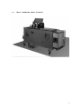
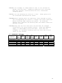
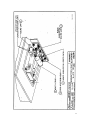
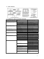
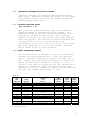
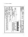
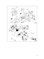
MICRO WELD
MODEL AUF-8
HEAVY DUTY
FERROUS
BUTT WELDERS
MICRO PRODUCTS COMPANY
SERVICE MANUAL
1
TABLE OF CONTENTS
1.0
2.0
3.0
4.0
5.0
6.0
7.0
8.0
9.0
10.0
11.0
12.0
13.0
1.0
SPECIFICATIONS
GENERAL OPERATING INSTRUCTIONS
BASIC OPERATING PARTS
BASIC OPERATING PARTS LOCATION
TYPICAL OPERATING SEQUENCE
SPECIAL ADJUSTMENTS
PREVENTIVE MAINTENACE
SUGGESTED SETTINGS
DIAGNOISTIC CHART FOR TROULBE-SHOOTING
ELECTRICAL SCHEMATIC
SAFETY REMINDERS
BUYERS GUIDE
PARTS LIST
SPECIFICATIONS
MODEL AUF-8
Welding Range Steel Wire
.500 to 1.312 in. dia.
Maximum Line Demand 460 Volt
137amps@100% duty cycle
433amps@10% duty cycle
274amps@100% duty cycle
866amps@10% duty cycle
90 KVA @ 50% duty cycle
Pneumatic, Foot Controlled
Pneumatic, Adjustable
4-Caster Wheels
Maximum Line Demand 230 Volt
Single Phase AC Transformer
Clamp Method
Upset Method
Mounting
Dimensions and Weights
Height Overall
Floor Space
Welding Die Height
Weight
50 in.
62 in. x 36 in.
43 in.
1700 LBS
2
FEATURES
•
•
•
•
•
•
•
•
Micro Weld quality and workmanship
Heavy-duty construction & components
Easy to operate controls
Low maintenance costs
Easy to set welding parameters
Safety electrical switch circuits
Heavy-duty weld heat selection switch
Sensitive straight slide movable headpiece assembly
2.0
GENERAL OPERATING INSTRUCIONS
2.1
ELECTRICAL HOOK-UP INSTRUCTIONS
First determine that available electrical service in your
plant corresponds to the nameplate rating located on welder
housing. Electrical wiring to welder must be of sufficient
size to deliver full ampere load with no appreciable loss
during weld cycle. The welder will not operate properly if
there is more than a 10% variation in the line voltage. In
general, the welder should be fused with a slow blow fuse
of the 100% duty cycle rating. The minimum power cable size
to the welder can be obtained by using this same current
rating.
Refer to National Electrical Code and local electrical
regulations for adequate power sizes; disconnect methods
and fusing guidelines.
Remember, line voltages to the welding machine are
potentially dangerous should the power cords be damaged or
severed. The welding voltages at the welding dies will not
harm an operator since they do not exceed 10 volts.
2.2
SAFETY PRECAUTIONS
(See section 11.0)
2.2.1 ELECTRICAL
Maintain electrical cable to welder in good repair. Welder
must be grounded and connections securely tightened. Heat
Switch must not be changed to new position while a weld
cycle is in process. Disconnect electrical service before
serving welder – high voltages are located within the base
of the welder.
3
2.2.2 MECHANICAL
Operator while using welder must wear safety glasses. Keep
all safety guards on welders and use properly. Operators
must be instructed on basic operation of unit to prevent
injury. Check nameplate rating and keep within material
size range for each welder.
2.3
WATER HOOK-UP
(If so equipped)
It is important that if a welder is to be operated for an
extended period of time and head heat up, water lines must
be connected to the welder. Connect hoses to inlet and
outlet provided at the back of the welder. Shut-off valve
should be installed in the inlet line and the hose from the
outlet should run to an open sight drain. Water should be
turned off when welder is not in use.
2.4
AIR HOOK-UP
Set air regulators for from 20 to 80 lbs. A safety pop-off
valve will be activated when air gauge is set for over 100
lbs.
2.5
WELDING DIES
The dies and shoes supplied with the welder will handle
most size and material types within the range of the
welder. For new weld applications consult the factory for
special die and shoe sets.
4
3.0
BASIC OPERATING PARTS
3.1
MODEL AUF-8
3.1.1 WELD HEAT SELECTION SWITCH
Welding heat is selected by means of a heavy-duty tap
switch with either eight or twelve steps of voltage. Number
one indicates the highest heat setting and number eight or
twelve indicates the lowest heat setting. The switch is
conveniently located on the lower front of the welder.
Note: The following items can be located on Print #B 7771
in Section 9.1.A.
3.1.2 HEADPIECE CLOSED SPACE ADJUSTING BOLT
The closed space-adjusting bolt is located on the movable
headpiece end plate. Refer to Item A.
3.1.3 HEADPIECE OPEN SPACE ADJUSTING BOLT
The open space-adjusting bolt is located on the upset
mechanism. Refer to Item E.
3.1.4 LIMIT SWITCH ADJUSTING BOLT
The limit switch-adjusting bolt is located on the lever bar
on the upset mechanism. Refer to Item F.
3.1.5 TOGGLE LINK
The toggle link is located on the upset mechanism. Refer to
Item I.
3.1.6 UPSET LEVER ARM
The upset lever arm is located in the middle of the upset
mechanism. Refer to Item I.
5
4.0
BASIC OPERATING PARTS LOCATION
6
5.0
5.1
5.2
5.3
5.4
5.5
5.6
5.7
TYPICAL OPERATING SEQUENCE
All insulating materials must be removed from conductors
where they contact lower welding dies.
Set weld heat selection switch to recommended chart
setting.
Set upset pressure to recommended chart setting (PSI).
Adjust the head open space to proper chart setting.
Place the stock into welding dies so wire ends meet midway
between each die. Clamp into position with foot valve
pedals.
Lower the flash guard and raise up on the operating lever
until it initiates the operation switch, hold for 1 to 3
seconds to assure a complete weld cycle.
Unclamp welded conductors.
Trim off weld burr so welded area is equal to parent
material diameter. Incomplete burr removal or undercutting
of the weld area will result in subsequent weld breaks.
6.0
SPECIAL ADJUSTMENTS (FIG. 9.1.A)
6.1
Item “A” is used for head closed space adjustment. This
may have to be adjusted as die and shoe inserts wear, for
this reason it’s best to keep like size grooves in one die
set. As the ends wear they can be used until an even
amount takes place then adjust closed headspace again.
When replacing worn dies with new or rebuilt ones, turn
bolt “A” in about ½” to prevent ends from being damaged
when adjusting new closed space.
To adjust new head closed space after new weld dies and
clamp shoes have been installed. Lift up on hand operated
air valve lever and hold in place with small wire through
ears on valve body and hole in lever. Adjust bolt “A”
until there is .010” between ends of weld dies. Lock bolt
“A” in place with locknut.
6.2
Item “E” head open space adjustments.
6.3
Item “F” limit switch adjustment. The trip nuts should be
adjusted to where plunger on limit switch is pushed down
7
when the dies are ¼” apart. Make final adjustment according
to welding chart. This adjustment is made with nothing in
welding dies and initiating the operating lever.
6.4
Item “I” toggle link. This changes the vertical motion of
the upset lever to a horizontal movement.
6.5
Item “I” upset lever. This lever pivots at the rear with
air cylinder pushing front end of lever up.
7.0
PREVENTIVE MAINTENANCE TECHNIQUE
Keep in Mind that these welders are precision built to last
many years, but will require good maintenance procedures.
They are designed to be as automatic as possible with a
minimum dependence on the ability of the operator. Those
must make adjustments thoroughly familiar with the
operating principles of the welders.
8
7.1 WELDING DIE NOTES
7.1.1 Welding dies and die shoes in poor condition are the
primary caused of bad welds.
7.1.2 Check die sets for excessive wear and replace if necessary.
7.1.3 Clean weld die bottoms to remove oxides with emery cloth
placed on a flat surface.
7.1.4 Clean die seats with emery cloth to brighten contact areas.
7.1.5 After cleaning of dies be sure to wipe off with soft clean
cloth.
7.1.6 Completely tighten dies into seats to assure a good
contact.
7.1.7 Worn dies will not hold stock during a weld cycle, replace
worn dies.
7.2 WEEKLY
7.2.1 Tighten all loose parts.
7.2.2 Check for water leaks (if applicable).
7.2.3 Check for air leaks.
7.2.4 Drain airline filter bowls.
7.2.5 Tighten all loose parts.
7.3 QUARTERLY
7.3.1 Repeat above service items.
7.3.2 Check grease requirements on clamp arms pivot shafts and
lubrication points.
7.3.3 Check anneal parts and replace all worn or broken
assemblies
7.3.4 Check contacts on magnetic contactor for worn contacts.
7.3.5 Clean heat switch contacts with low residue cleaner and
recoat with petroleum jelly.
7.4 ANNUALLY
7.4.1 Repeat previously noted items.
7.4.2 Check for wear in clap arm pivots.
7.4.3 Clean inside and outside of welder.
7.4.4 Check grease requirements on headpiece slide shafts, grease
lightly.
7.4.5 Caution: make sure that power supply is disconnected before
servicing welder in anyway!
7.5
WELDING DIES AND DIE SHOES INFORMATION
Description:
Welding dies – Lower conducting electrode and clamp jaw.
Welding die shoes – Upper clamping member.
Welding dies and die shoes in poor condition are the main
causes of bad welds.
Care of die sets:
7.5.1 Use a brass or fiber blade to remove particles of flashings
that build-up on die sets. Excessive flash build-up causes
die burns on material and shorting of die sets.
9
7.5.2 Do not attempt to clamp material that is not suited for
welder into die sets. Undersize materials will slip and
burn die grooves, oversize materials will overstress
clamping parts.
7.5.3 Do not use welding die sets for a vise.
not withstand the mechanical abuse.
These parts will
7.5.4 Whenever welding dies are replaced, clean bottoms of dies
and corresponding die seats to a bright and clean condition
before bolting them tightly into place. An oxidized
surface will insulate the welding dies and reduce effective
welding voltage.
7.5.5 Welding die set will wear with use and must be changed
occasionally for good welding results. Keep and adequate
supply of replacement parts available. Wire and rod
slippage is a problem caused by poor die sets and a major
cause of wire breaks.
8.0 SUGGESTED SETTINGS
Material
Model AUF-8
Steel Rod
Steel Rod
Steel Rod
Steel Rod
Size
inches
.500
.750
1.000
1.312
Weld
Heat
Setting
Die
Closed
Space
inches
Die
Open
Space
inches
7
6
5
1
.5
.5
.5
.5
1.5
1.5
1.5
1.7
Upset
Pressure
30
30
40
50
psi
psi
psi
psi
Clamp
Pressure
90
90
90
90
psi
psi
psi
psi
Limit
Switch
Setting
Upset
Arm
Movement
2
2.5
3
3
10
11
8.1 WELD EXAMPLES
9.0 DIAGNOSTIC CHART FOR TROUBLE SHOOTING
Welding Action
Welding action normal burr
does not extend beyond rod
Molten metal blown out and
material does not join
Weld area does not heat
enough to complete weld
Dry looking weld
Misalignment of rod
Rod ends buckle and not
welded
Welder inoperative
Variations in welds
Cause
Shear cut
Remedy
Increase stating space
High heat
Limit switch adjust
Small stock
Low upset pressure
Air system
Low heat
Transformer secondary
connection
Welding dies
Staring space
Upset pressure
Limit switch
Worn die grooves
Starting space
Welder head loose
Weld heat
Starting space
Upset pressure
Welding dies
Fuses
Time delay switch
Operating or limit switch
Heat switch
Contactor
Welding transformer
Auto-transformer
Stock slippage
Lower heat setting
Set to depress ¼”
Check nameplate rating
Increase upset pressure
Clean air filters
Increase heat settings
Clean and tighten
Input voltage
Loose transformer secondary
Loose welding dies
Binding movable headpiece
rod connection
Preparing rod end
Weld contactor
Time delay switch in weld
circuit
Clean and tighten
Decrease starting space
Decrease settings
Adjust
Replace die sets
Decrease staring space
Return for reconditioning
Increase heat
Decrease starting space
Decrease pressure
Clean or replacement
Check power supply
Check continuity of circuits
Check continuity of circuits
Tighten loose connections
Check continuity of circuits
Check continuity of circuits
Check continuity of circuits
Undersize stock
Replace worn dies
Set clamp pressure to 90 psi
Leaking clamp cylinder
Check power input
Only 5% drop permissible
Inadequate wiring
Clean and tighten
Clean and tight or replace
Remove all rod ends
Clean contact area
Replace rod cutter jaws
Require consistent cuts
Replace contacts and check
operation
Increase air stabilization
time-install timer on early
units
12
9.1
ELECTRICAL TROUBLE-SHOOTING OF WELDER
(Caution!! Extreme care should be exercised when making
these tests. Dangerous voltages are present in the welder.
Only persons familiar with electrical safety precautions
should perform these tests.)
9.1.1 TROUBLE-SHOOTING TABLE
(See section 9.1.3)
This electrical trouble-shooting table is furnished as a
suggested method of trouble-shooting the welder. The
individual steps of the table should be performed in the
order given, to make the tests valid. The electrical
schematic (section 10) furnished for these tests show the
table test points. The table may be used for welders with
a different but closely related wiring by using
corresponding test points. During all tests, line voltage
should be connected to L1 & L2 of the welder. The heat
switch should be set to the #1 position.
9.1.2 FINAL ELECTRICAL CHECKS
Set the heat switch to the number 1 position, connect the
voltmeter across the welding dies. Press the operating
switch. The meter reading will typically be less than 10
VAC. Consult the weld specification sheet for this value.
Rotate the heat switch through all settings. If the
voltage is not read at any setting, the heat switch may be
defective. Actuate the weld limit switch; observe the
reading goes to zero. Release the weld limit and operating
switches, the reading should remain at zero.
9.1.3
TEST
LEAD
CONNECTION
X1 X2
X2 FU1-1
X2 FU1-2
X2 PB1-1
X2 PB1-2
X2 LS1-2
X2 LS2-1
X2 LS2-2
X2 PB2-1
X2 PB2-2
X2 CR1Coil
L2 CR1-1
L2 CR1-2
METER
READING
115 VAC
115 VAC
115 VAC
115 VAC
115 VAC
115 VAC
115 VAC
115
115
115
115
VAC
VAC
VAC
VAC
Line voltage
Line voltage
PROBLEM
IF NO
READING
Bad control transformer
Bad fuse connection
Open fuse
Open wire to operating switch
Bad operating switch
Open flashguard switch
Open wire to weld limit
switch
Open weld limit switch
Open wire to anneal switch
Bad anneal switch
Bad relay
Open wiring to contactor
Bad contactor
PRESS
OPERATING
SWITCH
WELD
LIMIT
SWITCH
ACTUATED
PRESS
ANNEAL
SWITCH
X
X
X
X
X
X
X
NOTE: To perform repair consult section 13 for parts
identification.
13
10.0 ELECTRICAL SCHEMATIC
14
10.1 PNEUMATIC SCHEMATIC
15
11.0 SAFETY REMINDERS
The following accident prevention information is presented
to eliminate potential hazards while operating, inspecting
or repairing Micro-Weld electric resistance welding
equipment.
Important safety compliance information for Micro-Weld
Welders.
GENERAL
1. Qualified personnel, prior to using equipment, must
instruct an operator on basic operation and
malfunction methods.
2. Safety eyeglasses must be worn by all personnel
operating or servicing welders.
3. Use safety equipment properly and keep safety
equipment on welders.
4. Determine that both operating voltages and hertz
(cycles) of power supply correspond to ratings listed
on welder nameplate located on welder housing.
5. Check nameplate ratings and keep within capacities and
material categories stated therein.
6. Adjustments or repairs must be made by persons
thoroughly familiar with operating principles of
welder.
7. Welder must be disconnected from power supply prior to
maintenance or repair procedures.
ELECTRICAL
1. Refer to National Electrical Code and local
regulations for adequate electrical wiring to power
welder. Do not operate welder with inadequate
electrical power supply cords or cable.
2. All welders must be grounded through power supply and
welder ground connection terminal securely tightened.
3. All welders must be able to be disconnected from power
source either by a double breaking disconnect switch
or unplugged by standard rated plugs.
4. All welders must be fused to prevent injury should an
electrical malfunction occur. Welders must never be
fused for an ampere load that exceeds the ratings
stated on welder nameplate. Normally welders are
fused using the nameplate rated load; time lag
parameters functional to standard fuses allow this
specification.
5. Electric power cords to welder must be kept in good
condition. Report any damage or potential hazards to
maintenance personnel.
6. The weld heat selection switch, potentiometer or range
selection devices must not be changed to a new
position while a weld operation is in process.
16
12.0 BUYERS GUIDE
HOW TO ORDER PARTS:
You must provide
1. Machine Model
2. Machine Serial Number
3. Voltage
Then identify part(s) on part list (last page in book) and
provide MICRO with the circled number.
CALL MICRO at 800-872-1068
OR FAX MICRO at 630-787-9360
Provide MICRO with your company name and purchase order
number.
17
13.0 PARTS LIST
18
19
20
21
22