1
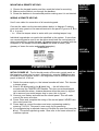
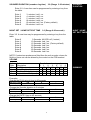
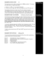
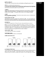
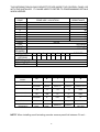
INSTALLATION
MANUAL
CEF AP28 CONTROL PANEL
With additional options
AP28
CONTENTS
Warnings
Standards
Warranty Statement
Product Description
Available Parts
Intended use
Specifications
Processor Version
Power Supply
Keypads
General
Factory Defaults
Installation
Mounting
Wiring
Battery
Detector Circuits
L+ as Latch Line
L+ as ID- (detector reset)
Sounders
Strobe
Keyswitch Connections
Aux DC power
PCB Layout
Mounting & wiring Keypads
Powering Up
Entering Engineering Mode
Programming
Chime
Sound options
Exit Time
Entry Time
Sounder Duration
Night & Hone Set Exit Time
Circuit Programming
Zone Selections
Extended Programming
Home Set Zone Selection
Engineer Access Code
Engineer Log Review
Engineer Test Options
Restoring Default Programming
Restoring Default Codes
Glossary Of Terms
Information Table
Sounder Wiring Chart
Fault Finding
Wiring Diagram
1
2
2
2
2
2
2
3
3
3
3
3
3
4
4
4
4
4
4
5
5
5
5
5
5
6
6
7
7
7
7
7
7
8
8
9
9
9
9/10
10
10
10
11
11
11/12
13
13
14
15
WARNINGS
Prolonged short circuit of any supply can cause damage to the unit. Take the necessary
precautions in not allowing liquids to spill on or into the unit.
STANDARDS
This unit conforms to EMC directive 89/336/EEC & LVD 73/23/EEC. This unit has been
tested and has proven to meet all current emission and immunity regulations as set out by
the EU. This unit conforms to the requirements of BS4737 part 1 1986 which relates to
security control equipment.
COPYRIGHT
This product is designed and manufactured by IntelliSense UK Ltd for City Electrical
Factors. IntelliSense UK retain all intellectual property rights for the hardware and software
use herein. No badging or re-badging of this product may be made without written
authorisation from both City Electrical Factors and IntelliSense UK Ltd.
PRODUCT DESCRIPTION
The AP28 is an 8 zone programmable microprocessor control panel using state of the art
technology and manufacturing techniques. The panel has many advanced features that can
only be found in more expensive control panels. These features include two user codes,
Chime, Fire, and Keypad PA. There are many options in the programming functions to
allow the control panel to be versatile and user friendly. This panel is the ideal choice for
residential or light commercial installations.
AVAILABLE PARTS
A selection of spares and extras are available. These are:•
Remote Keypad - giving full control over the control panel.
•
Spare PCB - for replacement in the event of failure.
These can be obtained from your original place of purchase.
INTENDED USE
This panel is designed to be used in residential and light commercial applications such as
homes, small shops etc.
2
PROCESSOR
VERSION
SPECIFICATIONS
SPECIFICATION FOR SOFTWARE REVISION NUMBER
V3.0
The software revision number is located on the top of the main processor
POWER
SUPPLY
Power Supply
Mains Supply Voltage
PSU output voltage
Maximum output current
Aux. current
Battery Fuse
Panel Quiescent
230 V AC Nominal
13.7 V Nominal
1 A (total)
500 mA Max.
1 A (20 mm)
40 mA
KEYPADS
Keypads
Supply Voltage
Quiescent Current
Active
Maximum number allowed
13.7 V
20 mA
45 mA
6
GENERAL
General
Normal operating temperature
Humidity
Dimensions
Control Panel Weight
Standby Battery
Standby Time (load dependant)
Cable Runs
Zone/circuits
Sounder
FACTORY
DEFAULTS
0°C to 40°C
10 to 90% R.H. non condensing
W 263 mm H 223 mm D 82 mm
2.7 kg Excluding Battery
7.0 Ah 12 V Rechargeable Lead Acid
24 hrs with 2.8 Ahr nom.
60 hrs with 7.0 Ahr nom.
Based on panel, Keypad, & 2 pir’s
40+20+25+25mA = 110mA Quiescent
100m max with 50mA load.
50m max with 7/0.2
100m max with 16/0.2 or 2 x 7/0.2
Factory Defaults
User/customer Code 1
User/customer Code 2
Engineer Code
Circuit 1
Circuit 2
Circuit 3
Circuit 4
Circuit 5
Circuit 6
Circuit 7
Circuit 8
Full Set Exit Time
Night set Exit Time
Entry time
Sounder Ring Time
Chimes
Programmable options
1234
Disabled (0000)
7890
Entry Circuit. (Fixed)
Alarm Circuit isolated in Night set.
Alarm Circuit.
Alarm Circuit.
Alarm Circuit.
Alarm Circuit.
Alarm Circuit.
P.A (Personal Attack)
30 Seconds
15 Seconds
30 Seconds
15 Minutes
Disabled
Non selected
3
INSTALLATION
Locate the control panel out of sight, such as in a hall, under stairs or in a
cupboard where connection is easy and the detector zone and mains
cables can be concealed. Avoid areas subject to high temperatures or
humidity such as next to a boiler, airing cupboard or conservatory.
Mounting
1.
2.
3.
4.
5.
INSTALLATION
PROCEDURES
MOUNTING
PROCEDURE
Remove the lid screws and remove lid.
Remove the PCB or keypad packaging.
Place the panel in the selected position and mark the three fixing holes.
Mount the Panel securely using all three mounting hole positions.
Attach the tamper spring and mount the PCB onto the support pillars.
WIRING THE CONTROL PANEL
ELECTRICAL SAFETY NOTICE.
THIS PRODUCT MUST BE EARTHED
This Power Supply must be permanently connected to the mains supply
in accordance with current IEE wiring regulation. A 3 amp fused spur,
installed by a qualified electrician, is strongly recommended.
MAINS POWER
WARNING
Any fault which could be mains related must be diagnosed and
corrected by a qualified electrician to ensure continued safe operation.
CAUTION: Under certain circumstances the transformer metalwork
can reach 70°C. this is normal and within prescribed limits.
Battery connection.
BATTERY
SPECIFICATION
Maximum battery size 12V 7.0Ah
This panel requires a standby battery to be fitted to provide power in the
event of mains failure. A valve regulated lead acid battery must be used.
Detector circuits
Connections are provided for up to eight detector circuits of which normally
closed detection devices must be used. A common tamper loop is provided
for all detection devices marked as 24 HR Tamper. One or more devices
may be connected to each alarm circuit. These should be connected in a
series configuration. These circuit connections are located to the bottom
right of the PCB (see diagram B).
PIR Latch Line (L+)
In the event of two or more detectors (motion sensors or glassbreak
detectors) being fitted to any single zone, latching detectors should be
used. The 'L+' connection provides this function. It is low (0 V) when
unset and high (12 V) when set. It should be connected to the appropriate
SET or LATCH terminal in your detector. See glossary for explanation.
4
DETECTOR
CIRCUITS
LATCH LINE
DESCRIPTION
DETECTOR
RESET
Detector reset (L+ when programmed for ID)
Some detectors require the removal of power to reset (e.g. Viper Plus® or
Smoke detectors). The L+ terminal can be programmed to be used as an 'ID'
output using option 7-4. The L+ terminal should then be used as the negative
supply for these devices. The positive supply should be taken from the AUX +.
SOUNDERS
Internal Sounders, Speakers, Strobe and Keyswitch Wiring.
DIAGRAM A
Keyswitch Connections
Open = ON
Z8 only
Closed = OFF
OFF
ON
A maximum of two 16 ohm speakers may be
fitted in parallel.
EXTERNAL
DEVICES
External Sounder & Strobe.
Diagram A shows the connection for external sounder and strobe. Please note
sounder trigger is applied negative. (Negative ring).
STS+
-R
AUXILIARY
POWER
Strobe switched negative trigger.
Sounder switched negative trigger
Sounder hold off/strobe positive supply.
Sounder hold off supply & sounder tamper feed (negative)
Sounder tamper return. (negative)
AUX DC - Detector power.
The auxiliary power is provided from connections marked 'AUX'. This is to
provide the 12 V supply for detectors e.g. movement or glassbreak detectors.
The auxiliary power output is rated at 500 mA max. (12 VDC nominal). See
diagram B
PCB BOARD
LAYOUT
DIAGRAM B
5
MOUNTING A REMOTE KEYPAD
1. Choose the keypad location and then mark the holes for mounting.
2. Make sure the cable is run through the backbox.
3. Screw the backbox in the selected position making sure it is not twisted.
WIRING A REMOTE KEYPAD
Use 6 core cable for connection of all remote keypads.
MOUNTING
REMOTE
KEYPADS
WIRING
REMOTE
KEYPADS
Connect the cable into the terminals shown below in diagram C making
sure each wire goes to a like named terminal in the panel. C goes to C, D to
D, + to + and
- to -. Wire the tamper wires in series with your existing tamper loop.
Individual keypads do not need to be identified to the system. If more than
one remote keypad is used it can be either wired back the control panel or
daisy chained from another keypad. All connections are in parallel with the
exception of the tamper circuit which MUST be wired in series. (see
glossary of terms for series and parallel examples).
DIAGRAM C
KEYPAD
DIAGRAM
POWERING UP
INITIAL POWER UP The lid should remain off the main control panel so
that engineer mode may be used. Alternatively, entering 7890 # can also
be used to enter engineer mode. If the engineers code is entered and the
panel is then left, it will set.
1. Switch the mains supply on, the internal sounder will start. This denotes
a tamper alarm.
2. Enter 1 2 3 4 followed by the # (hash) key - this will silence the
sounder and the TAMPER LED flashes. This has now acknowledged
and cancelled the alarm, however because either the panel or keypad
lid is removed your main tamper loop is open, this is normal.
3. Connect your battery and walk test the control panel. This will make
sure all the zones are clear.
4. Power Down and complete the wiring of the control panel. NEVER wire
the control panel live.
5. Power back up, cancel the alarm and enter engineering mode by
entering 7, 8, 9, 0. The panel is now ready for programming.
6. If no programming is required close any lids that are open and press the
# key. This exits engineering mode. Now refer to the users manual for
customer options.
6
INITIAL POWER
UP
NO
PROGRAMMING
NEEDED?
ENTER
ENGINEERING
MODE
To enter engineering mode, enter the engineering code and then press the #
(HASH) key. This forces the panel into engineering mode Note: If left
unattended for approximately 60 seconds it will revert to day mode.
EXIT
ENGINEERING
MODE
To exit engineering mode, confirm any options you have selected with the *
(STAR) key, then close ALL tamper circuits and wait for approximately 60
seconds after which the panel will automatically exit engineering mode or
pressing the # (HASH) key will manually exit engineering.
If you need to stay in engineering for longer unattended periods, once in
engineering mode open a tamper circuit. The easiest way to do this is to
remove the lid of the panel or keypad.
STAY IN
ENGINEERING
MODE
PROGRAMMING
PROGRAMMING
GENERAL
To exit all options press * to confirm the selection The accept tone will
sound.
CHIME
CHIME 2 1 (Range - any alarm zone)
Enter 2-1. Enter the keys corresponding to the zone(s) required to chime. On
exit from engineer mode zones selected will be set to chime, the customer may
disable chime only on zones programmed with this option (see user manual).
If no zones are selected the user will not be able to access their chime option
and an error tone will be heard.
SOUND
OPTIONS
TIMERS
EXIT TIME
SOUND OPTIONS 2 2
Enter 1
Enter 2
Disable exit / entry sounds in part and home set
Disable accept / error sounds in part and home set
EXIT TIME 3 0 (Range 10-90 Seconds.)
Enter 3-0. A new time can be programmed by entering a key from the table.
Enter 1
Enter 2
Enter 3
Enter 4
Enter 5
Enter 6
10 Seconds. Led 1 on.
15 Seconds. Led 2 on.
30 Seconds. Led 3 on. (Factory default)
45 Seconds. Led 4 on.
60 Seconds. Led 5 on.
90 Seconds. Led 6 on.
ENTRY TIME
ENTRY TIME
3-1 (Range 10-90 seconds)
Enter 3-1. A new time can be programmed by entering a key from the table.
Enter 1
Enter 2
Enter 3
Enter 4
Enter 5
Enter 6
10 Seconds. Led 1 on.
15 Seconds. Led 2 on.
30 Seconds. Led 3 on. (Factory default)
45 Seconds. Led 4 on.
60 Seconds. Led 5 on.
90 Seconds. Led 6 on.
7
SOUNDER DURATION (sounder ring time)
3-2 (Range 3-20 minutes)
SOUNDER
DURATION
Enter 3-2. A new time can be programmed by entering a key from
the table.
Enter 1
Enter 2
Enter 3
Enter 4
Enter 5
Enter 6
3 minutes. Led 1 on.
4 minutes. Led 2 on.
5 minutes. Led 3 on.
10 minutes. Led 4 on.
15 minutes. Led 5 on. (Factory default)
20 minutes. Led 6 on.
NIGHT SET / HOME SET EXIT TIME
3-3 (Range 0-90 seconds)
NIGHT / HOME
SET EXIT TIMER
Enter 3-3. A new time may be programmed by entering a key from the
table.
Enter 0
Enter 1
Enter 2
Enter 3
Enter 4
Enter 5
Enter 6
0 Seconds. All LED's off ( Instant ).
10 Seconds. Led 1 on.
15 Seconds. Led 2 on. (Factory default)
30 Seconds. Led 3 on.
45 Seconds. Led 4 on.
60 Seconds. Led 5 on.
90 Seconds. Led 6 on.
NOTE: If extension speakers are fitted then the exit sounder volume for
Night or Home set can be altered by the control on the PCB marked
VOLUME
Option
Code
3-0
3-1
3-2
3-3
Option
Description
Exit Time (secs)
Entry Time (secs)
Sounder Duration (mins)
Night / Home Exit (secs)
Results from choosing option no.
0
1
2
3
4
5
6
10 15 30 45 60 90
10 15 30 45 60 90
3
4
5
10 15 20
0 10 15 30 45 60 90
Examples
Change the FULL set exit time to 60 seconds
3-0
5
ENTER THIS
Description
Choose full set
*
Select 60 seconds
Change the Sounder duration to 3 minutes
3-2
1
ENTER THIS
Description
Choose sounder
*
Select 3 minutes
Change the ENTRY time to 45 seconds
3-1
4
ENTER THIS
Description
Choose entry
Confirm selection
Confirm selection
*
Select 45 seconds
8
Confirm selection
SUMMARY
CIRCUIT
PROGRAMMING
CIRCUIT PROGRAMMING
4 (Range 2-7)
Circuits 2 - 7 can be reprogrammed to suit your requirements. Circuit 1 is
fixed as a Final exit circuit. Circuit 8 has limited options.
ENTER
4-2
4-3
4-4
4-5
ZONE
SELECTIONS
PROGRAM ZONE
2
3
4
5
ENTER
4-6
4-7
4-8
PROGRAM ZONE
6
7
8
Select the circuit you wish to alter, it may then be programmed by entering one
key from the following table.
N/S = Night Set
Option no.
1
2
3
4
5
6
7
8
Zones 2-7
Alarm
Alarm with walk through
Alarm & Isolate in Night Set
Alarm, Walk through & Isolate in N/S
Alarm, Walk through & N/S Entry
Fire
Entry Route
P.A
Zone 8
Alarm
Fire
PA
Keyswitch
SEE GLOSSARY OF TERMS (p.11) FOR DESCRIPTIONS OF ZONE TYPES etc.
To program zone 3 as an “Entry Route” enter - 4 3 7 *
To program zone 8 as a “Keyswitch” enter - 4 8 4 *
Momentary keyswitch
Turn and hold for 0.5 sec = FULL SET
Turn and hold for 2.3 sec = PART SET
EXTENDED
PROGRAMMING
EXTENDED PROGRAMMING OPTIONS
Enter 7 - 1
Enter 7 - 2
Enter 7 - 3
Enter 7 - 4
Enter 7 - 5
Enter 7 - 6
Enter 7 - 7
Enter 7 - 8
HOME SET
ZONE
SELECTION
7 (Range 1-8)
Disables sounder & strobe in night set.
Keypress tamper alarm (after 16 incorrect keypresses)
Full set door sense setting.
Convert L+ to ID- output.
Allow Manual Isolation of Zone 1 (Entry/Exit) In Night Set.
Remote Keypad PA Enable (Operated by * & # ).
L+ signals first to alarm.
Inhibit strobe in Night and Home Set and testing. (For
speech dialler connection)
HOME SET ZONE SELECTION
8 (Range 1-8 N/A if Fire or PA)
The Home Set feature enables parts of the premises to be alarm protected
while other parts are occupied. This is similar to Night Set except that an
Exit/Entry route is not required as part of the Setting or Unsetting procedure.
In programming mode press 8 to select Home Set zone selection mode, then
by pressing the keys 1-8 on the keypad you will select which zones you want
ISOLATED during home set. As a key is pressed, its relevant LED on the
display will toggle on or off. Any LED’s that are ON will be ISOLATED during
home set and any that are off will remain ACTIVE.
9
ENGINEER ACCESS CODE
1-1
ENGINEER
ACCESS CODE
The engineer access code is programmed to 7890 by default. To change
this code (while in engineering mode):
1. Enter 1-1. LEDs 1, 2, 3 and 4 will illuminate.
2. Enter the new 4 digit code. After each keypress one LED will go out.
The speaker will emit an accept tone if the new code is accepted.
If the speaker emits an error tone, then your new chosen code is invalid.
This could be due to a conflict with another code. At this time your old
access code is still valid. Repeat the procedure using a different code.
ENGINEER EVENT LOG REVIEW
5 (Choices of set & unset)
ENGINEER
LOG REVIEW
The Panel stores the last set and unset states and the last alarm event. The
log is arranged into SET and UNSET events. Log entries indicate the first
and subsequent alarms and also isolated circuits. First to alarm is shown
by the LED being ON continuously. Subsequent alarms are shown by the
LED(s) flashing and isolated circuits by the LED(s) pulsing slowly. The
buzzer sounds whilst reviewing the SET logs and is silent while reviewing
the UNSET logs.
To view the engineers log press the 5 key from the program mode. The log
starts viewing DAY 1 SET. View the remaining logs by pressing the
relevant key 2 for 2nd, 3 for 3rd and so on up to 9. Press the 0 key to get the
last alarm condition.
The # key alternates between SET and UNSET logs and can be used at
any time.
ENGINEER TEST OPTIONS
6 (Range 0-5)
To conduct testing activities first press the 6 key from within engineering
mode and then one of the option below.
Enter 0
Enter 1
Enter 2
Enter 3
Enter 4
Enter 5
Internal buzzer ( entry exit sound etc. )
Internal Sounder ( Alarm sounds from speaker / keypad )
External Sounder
External Strobe
L+ Terminal( even if programmed as ID- )
FULL LOAD ( Everything enabled )
10
ENGINEER
TEST OPTIONS
FACTORY
DEFAULTS
FACTORY PROGRAMMING DEFAULTS 9-9
Restoring programming Defaults.
RESTORE
DEFAULT
PROGRAMMING
RESTORE
DEFAULT
CODES
Enter 9-9, The sounder will give a rapid pipping sound, wait for 5 seconds, an
accept tone sounds, the factory programming defaults are restored. The user
and engineer codes do not change.
Note: If any keys are pressed this procedure will be aborted.
Restoring Code Defaults
1. Place the small link supplied with the spare fuses, on the memory link.
This is positioned above the volume control and is labelled “Memory
Default”.
2. Remove the mains and battery supply.
3. Wait a few seconds then re-connect the battery and then the mains
Refer to page 6 regarding initial power up. The speaker will emit the accept
tone and the factory user code defaults will be restored.
4. Be sure to remove the link .
Locking the Engineer Code
Use this option with care. You can lock the engineer code to prevent
unauthorised alteration. To enable the engineer code must end in 9. If the
engineer code is lost, it will not be possible to enter engineer mode, the PCB
will need to be replaced. This is considered to be a “Chargeable repair”.
GLOSSARY OF
TERMS
GLOSSARY OF TERMS
FULL SET
This is a setting method normally used when leaving the premises. Full system
armed.
NIGHT SET
This is a setting method normally used when going to bed
HOME SET
This is a setting method normally used for high security protection whilst still
inside the premises. For example an antiques cabinet etc.
ALARM
This is a zone that will trigger the panel when activated, providing the panel is
set.
WALK THROUGH
This zone will be disabled during an entry period.
ISOLATE IN NIGHT SET
This simply means the zone will be disabled when the panel is NIGHT SET. For
example downstairs
NIGHT SET ENTRY
When the panel is NIGHT SET the zone, when activated, will start the entry
timer but if the panel is FULL SET then this zone will acts as an ALARM zone.
11
ENTRY CIRCUIT
This will start the entry timer when activated providing the panel is set.
FIRE (for use with smoke detectors etc.)
A zone that when activated emits an ascending sound from any internal speakers.
If the panel is set, external sirens and strobes will also sound but in an unset state
the external sounders will pulse every two seconds.
TAMPER
This is a loop that should run through every device on your system. If broken, it
triggers the internal speakers. If the panel is set, the external sounders and
strobes will also trigger. The tamper LED is shown on the keypad as TPR.
CHIME
Chime is similar to a doorbell. This can be used to alert a user to a certain zone
being triggered during the day.
DOOR SENSE SETTING
This allows you to have a variable FULL SET EXIT TIME. You can program the
EXIT time to maximum and when you full set the system, the exit time will drop to
8 seconds as soon as the EXIT door has closed thus avoiding the preset exit time.
KEYSWITCH
This allows the panel to be Full set, Part set, Unset and Reset via zone 8.
Note: To use the keyswitch for setting and unsetting, connect to zone 8 and
program that zone to be KEYSWITCH. To set the panel, turn the key so that the
contacts are open, hold in this position for about a second for full set or about 2
seconds for night set. To unset the panel, turn and hold for about ½ second. To
reset open and close the keyswitch after an alarm condition.
THE ACCEPT TONE
This is heard when an action is accepted.
THE ERROR TONE
This is heard when an action is not accepted.
SERIES AND PARALLEL
LATCHING DETECTORS
These detectors, when triggered during a set period, latch on to aid the process of
alarm event origin checking. These detectors are only normally used if many
detectors are to be used on a single zone but are to cover a large area of space.
12
GLOSSARY
OF TERMS
THIS INFORMATION SHOULD BE KEPT EITHER INSIDE THE CONTROL PANEL OR
WITH THE INSTALLER. IT CAN BE USED TO REFER TO PROGRAMMING DETAILS
WHEN NEEDED.
ZONE
1
2
3
4
5
6
7
8
TIMER
FULL
NIGHT
EXT
SOUNDER
TICK BOX
1
EXTENDED
OPTIONS
BATTERY VOLTAGE
AUX. VOLTAGE
INSTALLED BY
ZONE USE / LOCATION
RESISTANCE
Ω
Ω
Ω
Ω
Ω
Ω
Ω
Ω
VALUE
SECONDS
SECONDS
MINUTES
2
3
4
5
6
7
8
CHECKED
V
V
SOUNDER CONNECTIONS
CONTROL
PANEL
SONADE 2000
FLASHGUARD XL+
STARLIGHT 2000
AG 6 & AG 8
NOVA GUARD 2+T
SPIRIT AU1000
GENERAL
TERMINALS
ST-
S-
+
-
-R
STROBE-
B
D
A
T
STROBE-
SIREN-
SUPPLY+
SUPPLY-
TAMPER OUT
ST
-R
+H
-H
RTN
ST-
-SW
V+
V-
RET
STROBE-
S-
12V+
12V-
R
STB-
TRG-
HOLD OFF +
HOLD OFF
-
RTN-
STROBE
TRIG -
SIREN
TRIG -
SUPPLY+
SUPPLY-
TAMPER
RETURN
NOTE: When installing a self-actuating sounder remove panel link between R- and -.
13
FAULT FINDING
A selection of common known problems and solutions are listed below.
Problem
Cause
Answer
Programmed 7-5 but zone
1 will not isolate in night
set.
Zone 1 is permanently lit
Have not MANUALLY isolated zone
when setting panel.
When night setting enter
code * 0 * 1.
Memory default link is on.
PA will not work on the
keypad
Mains light not on.
Battery not taking over after
mains fail
Remote keypad not
responding
Not holding * & # long enough or
option not enabled
No mains
Battery fuse blown or battery not
connected or flat battery.
Remove link.
Check 24hr tamper, sounder tamper
and all devices for an open tamper
loop.
Be sure to HOLD * & # until the alarm
activates. Enable option 7-2.
Check fuse & mains supply
Connect battery and check 1A
battery fuse. Fit new battery.
Incorrect wiring
Check wiring. C to C & D to D.
Zones failing to activate.
Incorrect wiring
Zone activates during entry
Seeing an alarm zone on entry or
deviating from entry route.
Zone activates even in day
mode
Programmed to PA or FIRE.
Tamper will not clear with
lid on.
Tamper loop open
Make sure the devices are wired in
series NOT parallel.
Make sure all zones on entry route
are programmed with walkthrough.
Do not deviate.
Reprogram the zone to be an alarm
zone or similar.
If you are still experiencing problems then contact our technical helpline with information at
hand regarding your situation. If your problem stems from wiring, you may be required to
write down wiring instructions so have a pen and paper at hand.
General questions & Answers
Question
Answer
Yes, make sure tampers are in series and
do not exceed the current limit
Yes, connect between AUX+ and S-. Be
sure not to exceed maximum current
rating.
While it is better practice to limit the
number of detectors per zone, upto 10 may
be fitted. Zone resistance should not
exceed 50 ohms.
Yes, if the engineer code is entered the
panel will start the set. The engineer code
will also unset if the panel was set using
the engineer code, it will not unset if a user
set the panel.
The panel will re-arm. Any zone in fault
will be temporally isolated and will re-arm
when the fault clears.
Any further alarm activation’s will trigger
the bells again for the selected time. If any
zone activates three times in succession it
will be isolated. Alarms can occur from
other zones.
Can two bell boxes be used on the system
Can a “sound bomb” be installed
How many PIR’s can be connected to a
zone
Can the engineer set the panel without the
need of a user code
What happens if the zone is still in fault
when the bell cuts off
Will there be any further alarms
14
Wiring Diagram
City Electrical Factors
Unit 2 Arkwright Court
Fylde Industrial Estate
Blackpool
FY4 5DR
Technical support 01253 792898
Printed & Manufactured in China by IntelliSense. Document No F-051-176-01 Rev B
15