1
G
d
gl
!
Supplement to the
R O L L S . R O Y C EA N D B E N T L E Y
A U T O M A T I C G E A R B O X S E R V I C EM A N U A L
N
6
GEARBOX REMOVAL AND INSTALLATION -
SI CARS
GEARBOX REMOVAL AND INSTALLATION -
52 CARS
!
o
lr
I
i
I
l
x
l
d
CN
F
CI Rolls-RoyceLimited (1962)
L
3
F
Published by
The TechnicalPublicationsDepartment
R O L L S - R O Y C EL I M I T E D
Pvm's Lane,Crewe
l T S D P u b l i c a t i o n2 0 3 4 )
-rl
C
IV
-l
o
-
N
$
P r i n t e d i n E n g l a n d b y C h o r l e y & P i c k e r s g i l lL i m i t e d L e e d s
II
L
G E A R B O X R E M O V A L A N D I N S T A L L A T I O N- S I C A R S
d
tL,1
c
-o
f
t
0
.
The procedurefor the removal and installation of
the gearboxon Sl cars is very similar to that described
in Chapter 3, Section I of TSD 47 I, Automatic
G e a r b o x S e r v i c eM a n u a l . A s t h i s i s t h e c a s e .i t w i l l
only be necessaryhere to note major differencesso
that the procedure for Sl cars may be obtained bv
r e a d i n gt h e s en o t e si n c o n j u n c t i o nr v i t h T S D 4 7 1 .
Gearbox - to remove
N
a
L
I
l!
P l a c et h e c a r o v e r a p i t o r u p o n a r a m p o r s t a n d s :
this is necessaryto enablethe gearbox to be lowered
when disconnectedfrom the engine. To prevent the
car from moving, chock both of the front wheelsand
o n e o f t h e r e a r w h e e l sw i t h w o o d e n b l o c k s . J a c k
so that the
the other rear wheel clear of the -qror-rncl
p r o p e l l e rs h a f t c a n b e r o t a t e d .
D i s c o n n e ct h e b a t t e r l.
Exhaust pipes
It is not necessaryfor the exhaust pipes to be
removed.
Control rods and brake servo motor
Each of the rear shock dan.rpersis corrtrolledbv a
s o l e n o i d :n o r i d e c o n t r o l r o d o r l e v e r i s t h e r e f b r e
fitted.
Disconnect the handbrake cable at tlie lever
adjacentto the mastercylinder and tie the cableclear
of the servo motor.
v
N
a
F
Propeller shaft
Remove the four nuts securingthe propeller shaft
to the gearbox. [To preventthe propeller shaft from
turning whilst these nuts are released,selectreverse
gear by turrring the selectorshaft on the gearbox as
far as possible towards the rear of the car (anticlockwise.)l
Remove the split pin and castellatednut securiltg
the propeller shaft centre bearing support bracket to
the chassisframe; slide the shaft towards the rear of
the car.
Rear mounting
Before disconnectingthe rear mounting, drain the
fluid from the gearboxand fluid coupling as follows:
Remove the gearboxdrairr plug and aluminium
s e a l i n gw a s h e r :d r a i n t h e f l u i d i n t o a s u i t a b l ec o r r t a i n e r
then refitthe plug.
Renroe
r t h e s i r s e t s c r es\ \ r e t a i n i n g t h e f l y w h e e l
l o u e r c o v e r .t h e r rr e n t o v et h e c o v e r . R o t a t et h e e n g i n e
llvwheel to bring the fluid coupling drain plug to its
lowest position, then remove the plug and sealing
washer. Drain the fluid from the coupling into a
suitablecontainerand refit the drain plug.
On left-hand drive cars, remove the nut and washer
securing the rubber-mounted isolating stay to the
left-handside cover of the gearbox;withdraw the
i s o l a t i n gs t a r f r o n r i t s a n c h o rb o l t .
\ o t i e r o c l so r t r a l t s \ e r s ct o r q u e r e a c t i o r tb r a c k e t s
a r e t i t t e dt o t h e s ec a r sa n d t h e p r o c e d u r ef o r r e n r o v i n g
t h e r e a r m o u n t i n gi s a s f o l l o u s :
Place a jack under the rear of tlie engine surnp.
using a pieceof wood betweenthe jack head and the
sump to spread the load. Raise the jack sufficierrtly
to take the load off the gearbox rear mounting.
the gearboxrear mounting by removing
Discorrrrect
the centrebolt. Renror"ethe two mounting bolts from
each end of the support bracket and remove the
bracket.
Before finally disconnectingthe gearbox from the
engine, support the gearbox in a cradle'attachedto
the lifting platform of a trolley jack (similar to that
s h o w ni n F i g u r e8 . C h a p t e r3 , S e c t i o nI o f T S D 4 7 1 ) .
Fluid coupling and bell housing
Disconnect the two halves of the bell housing by
removingthe six setscrews.To gain accessto the two
setscrewsat the top of the bell housing, remove the
two rubber covers which are a pressfit in the front
floor of the car. Remove the two dowel bolts (one
fitted at the bottom of each side of the bell housing)
by unscrewingthe nuts and driving out the bolts.
C h a n g i n ga G e a r b o x o r E n g i n e
The noteson this subjectin Chapter 3, Section 1 of
T S D 4 7 1 a p p l y e q u a l l yt o S l c a r s .
Gearbox - to install
Gearbox rear mounting
Raise the gearbox sufficientlyto permit the transversemounting bracketto be fitted to the chassis
frame. Secureeach end of the bracket to the chassis
with two bolts. Lower the gearbox onto the bracket
a n d l o c a t ei t w i t h t h e c e n t r eb o l t . T h e t r o l l e y j a c k
may then be loweredand withdrawn from beneaththe
car.
Throttle and selector controls
The gearbox selector controls are adjusted, if
n e c e s s a r yi ,n a m a n n e r s i m i l a r t o t h a t d e s c r i b e di n
' G e a r b o x R e m o v a l a n d I n s t a l l a t i o n- 5 2 C a r s '
(seePage3).
Set and adjust the throttle control linkage as
i n S e c t i o nK 5 o f T S D 7 2 9 . 5 1 a n d 5 2 W o r k described
shop Manual.
:.
Road test
5'
Before testing the car on the road. fill the gearbox
w i t h A u t o m a t i c T r a n s m i s s i o nF l u i d a s d e s c r i b e di n
T S D 4 7 l , C h a p t e r 2 a n d r u n t h e e n g i n ef o r a f e w
minutes with the gear range selector in Neutral.
C h e c kt h e u n d e r s i d eo f t h e g e a r b o xf o r l e a k so f f l u i d .
f
ra
0e
f
Test the car on the road as describedirr SectionK5
of TSD 729,Sl and 52 Workshop Manual.
lf correct automatic char.rges
are not obtained after
adjustment of the controls, it will be necessaryto
remove the gearbox sump and adjust the bands as
d e s c r i b e di n T S D 4 7 1 .C h a p t e r3 , S e c t i o n6 .
W h e n a u t o r n a t i c_ g e acr h a n - e easr e o b t a i n e d s a t i s f a c t o r i l l . c h e c k f i n a l l r t h a t t h e r e a r e n o f l L r i dl e a k s .
t h e n t c l p - u pt h e g e a r b o r a n d r e f i t t h e u n d e r s h i e l d s .
#
;
-.1
(t
-
N
tI - - -
GEARBOX REMOVALAND
INSTALLATION -
52 CARS
=
;!
c
Gearbox
o-
-
to remove
P l a c et h e c a r o v e r a p i t . o r u p o n a r a m p o r s t a n d s i
t h i s i s n e c e s s a rtyo e n a b l et h e g e a r b o xt o b e l o w e r e d
w h e u d i s c o n r r e c t eldr o m t h e e n g i n e . T o p r e v e n tt h e
car from nroving, chock both of the front wheels
and one of the rear wheels with wooden blocks.
J a c k t h e o t h e r r e a r w h e e lc l e a ro f t h e g r o u n d s o t h a t
t h e p r o p e l l e rs h a f tc a n b e r o t a t e d .
D i s c o n n e ctth e b a t t e r l.
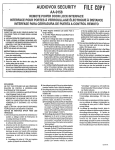
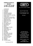
On right-hand drive cars, refer to Figure 2 for
i d e r r t i f i c a t i oorfr t h e l e re r s .j o i n t s .e t c .
Remove the gearbox control cross-shaft from
beneath the gearbox by releasingthe lock-nut and
a d j u s t i n gs c r e wo n e a c ho f t h e f o u r b a l l j o i n t s ( 3 . 4 . 6
a n d 8 ) ; d i s c o n n e ct h e l e v e r b a l l p i n s f r o m t h e b a l l
sclck ets.
R e r . n oer t h e s e t s c r esu s e c u r i n gt h e g e a r b o rc o n t r o l
a s s e n r b l rs t a y ( 2 ) t o t l i e c h a s s i sr i g l r t - h a r r ds i d e rlenrber.
R e r n o r ct h e s e t s c r e r iasn d p l a i n r r a s h e r s e e u | i n S
R e m o r e t h e n u t . b o l t . w a s h e r sa n d d i s t a n c et u b e
t l i e i n n e r l e t i a n d i n n e r r i g h t - h a r r du n c l e r s h e ettos t h c
f
i
o
m t h e g e a r s e l e c t o rc o n t r o l p i v o t ( l ) ; r e m o v et h e
r
e
m
o
v
e
i
t
i
s
n
o
t
the undersheets:
c h a s s i sf r a m e a n d
assen.rbly.
o
u
t
e
r
r
i
g
h
t
h
a
n
d
u
n
d
e
r
s
h
e
e
t
.
control
n e c e s s a rtyo r e m o v et h e
Gearbox and throttle controls
N
6
I
tr-
N o t e : U n d e r n o c i r c u n r s t a r t c emsu s t t h e
lerrgth adjustn-reno
t f the control rods
b e a l t e r e du h e n t h e l ' a r e r e t . t . t o r e c 1 .
D i s c o n n e ct h e r e a r e r r c o
l f t h e c o u p l i n gr o d ( 7 ) b y
p1'1.
[ c r t t , 'i \l l s t l r e. 1 r l i 1
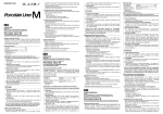
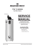
On left-handdrive cars, refcr to Figure I lbr iderrtif i c a t i o no f t h e l e l ' e r sj.o i n t s . e t c .
R c l e a s et h e p i r r c h b o l t a n d a d i L r s t i n -ssc r e w f i t t e d
a t t h e l o \ \ ' e re n d o f t h e c o n t r o l r o c l( 1 0 )a r r dw i t h d r a w
t h e s o c k e tf r o m t h e b a l l p i n .
R e m o r . et h e u u t a n d w a s h e r r e t a i n i n gt h e r u b b e r
r n o u n t e di s o l a t i n gs t a y ( 4 ) ; w i t h d r a w t h e i s o l a t i n g
stay from its anchor bolt.
R e l e a s et h e l o c k - n u t a n d b a l l j o i n t a d j u s t i n gs c r e w
on the control rod (6); disconnectthe ball socketfrom
t h e l e v e r . T h e g e a r b o xc o n t r o l a s s e m b l yc a n t h e n b e
lifted clear of the gearboxonto the chassisframe.
d
o
U)
F
D i s c o n n e c tt h e r e a r e n d o f t h e T . V . r o d ( 5 ) b y
r e m o v i n gt h e s p l i t p i n a r r dc l e v i sp i n .
R e m o v et h e n u t . b o l t a n d w a s h e ra t t h e c r o s s - s h a f t
bracket(9) and so disconnect he rubber-mounted
c o n n e c t i n lgi n k .
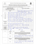
Brake control rods and servomotor
Refer to Fi-sure3 for identificationof the control
rodsand levers.
Release
t h e p i n c h b o l t s e c u r i n gt h e t h r o t t l el e v e r( 5 )
to its shaft: withdraw the lever.
On left-hand drive cars. remove the intermediate
rod (12)as follows:
Removethe rrut, bolt and washersat the lower end
o f t h e c o n n e c t i n gl i n k ( 3 ) .
Remove the split pin and clevis pin from the bell
crank leverfitted on the chassisleft-handside-member.
Releasethe pinch bolt and adjusting screw at the
upper end of the throttle control rod (1) and disconnect the ball socket from the control lever.
Remove the split pin and remove the castellated
nut and washerssecuringthe throttle lever (2) to the
bell housing.
Releasethe lock-nut and unscrewthe intermediate
rod from thejaw (13) fitted to the bell crank lever on
the chassisright-handside-member;the lock-nut must
be retained approximatelyin position relative to the
intermediate shaft to facilitate adjustment on reassembly.
The throttle controls can now be Iifted clear of the
gearbox without further dismantling.
On right-hand drive cars, unhook the pull-off spnng
(9) from the on-stop bracket (6).
L
tll
.:177-
t7
^
-,-ro^t
|
/,
.l
5
=
;
o
IJ
-
(h
tJ
A
Fig. 1
Gear selector and throttle controls
left-hand drive
late 52 cars
E
On all cars, uncouple the handbrake cable from
lever (3) by removing the split pin. washer and clevis
pin.
t
l rl
;
R e m o v et h e 2 B . A . n u t a n d b o l t s e c u r i n gt h e h a n d brake cable clip to the engine right-hand rear
r n o u n t i n ga n d l i f t t h e c a b l ec l e a r o f t h e s e r v om o t o r
a n d a d j a c e n ct o m p o n e n t s .
D i s c o n n e ctth e b r a k e r o d ( 7 ) a s f o l l o w s :
Removethe setscrewretainingthe locking plate on
the rear end of the brake rod (7) and remove the
locking plate. Withdraw the clevis pin and lift the
brake rod clear of the servo levers.
D i s c o n n e c t h e r e a r b r a k e l i n k a g ec o n t r o l r o d ( 4 )
a t t h e o u t e r s e r v ol e v e r( 5 ) b y r e m o v i n gt h e s e t s c r e $
r e t a i r r i n gt h e l o c k i n gp l a t ea n c iw i t h d r a r i i n gt h e c l e i i s
p i n . L i f t t h e c o n t r o lr o d c l c a ro f t h e s e n o l e r e r s .
Disconnect and remove tl.re foru'ard and reverse
brake rods (fitted between the servo levers arrd the
m a s t e rc y l i n d e ro p e r a t i n gl e v e r ) a s f o l l o w s :
al
a
=
-o
I!
Remove the setscrewsretaining the locking plates
on the forward ends of the upper and lower brake
r o d s ; r e m o v e t h e l o c k i n g p l a t e sa n d w i t h d r a u ' t h e
c l e v i sp i n s .
R e m o v et h e r r u t . b o l t . i i ' a s h e r sa n d d i s t a n c en i e c e r
s e c u r i n gt h e r e a r e n d o f e a c ho f t h e b r a k e r o d s t o t h e
m a s t e rc y l i n d e ro p e r a t i n gl e i e r . n o t i n g t h e p o s i t i o n s
o f t h e d i r t a n c ep i e c e s .
Scribea mark showingthe alignmentof the chassis
fiame arrd the on-stop bracket (6). Remove the nut
and bolt from the front of the or.r-stopbracket.
s l a c k e nt h e r e a r n u t a n d b o l t a n d s w i n g t h e o n - s t o p
bracketclear of the servolevers.
R e m o v et h e s e t s c r e ws e c u r i n gt h e s e r v o m o t o r t o
the gearbox and remove the servo ntotor complete
r ri t h i t s s e a l i n gw a s h e r .
v
6l
a
F
Remove the two setscrewssecuringthe crankcase
breather to the crankcase. then remove the two
setscrewssecuringthe breather pipe assemblyto the
flywheel bottom cover; withdraw the breather pipe
assemblyfrom beneaththe car.
Remove the six setscrewsretaining the flywheel
bottorrrcover arrd rentovethe cover.
R e r n o v et h e g e a r b o x d r a i n p l u g a n d a l u m i n i u m
s e a l i n gw a s h e r ;d r a i n t h e f l u i d i n t o a s u i t a b l ec o n t a i n e r
then refit the plug.
Rotate the engine llywheel to bring the fluid
coupling drain plug to its lowest position. then
r e m o v et h e p l u g a n d s e a l i n gw a s h e r . D r a i n t h e f l u i d
f r o m t h e c o u p l i n g i u t o a s u i t a b l e c o n t a i n e r .t h e n
r e fi t t h e d r a i n p l u g .
D i s c o r r n e ctth e s p e e d o n r e t ecrl r i v ea t t h e g e a r b o x .
R e m o l e t h e f o u r n u t ss e c u r i n gt h e p r o p e l l e rs h a f tt o
t h e g e a r b o xo u t p u t f l a n g e . ( T o p r e v e n tt h e p r o p e l l e r
shaft fronr turning whilst these nuts are released.
selectreversegear by movir.rgthe selectorlever on the
gearboxas far as possibletowards the rear ofthe car.)
R e m o v et h e s p l i t p i n a n d c a s t e l l a t e dn u t s e c u r i n q
the propellershali centre bearing support bracket
t o t h c c h a s s i sf r a n r c : s l i c l et h e s h a t i t o u , a r d st h e r e a r
of thecar.
D i s c o n n e c tt h e s t a f t e f n r o t r l r l e a d a t t h e m o t o r .
R e m o v e t h e t h r e e s e t s c r e w sr e t a i n i n g t h e s t a r t e r
m o t o r . t h e n r e m o v et h e m o t o r .
R e m o v e t h e s e t s c r e w s e c u r i n gt h e f l u i d c o u p l i n g
outer cover to the engineflywheel,taking care not to
m i s p l a c et h e b a l a n c ew e i g h t s( i f f i t t e d ) .
R e m o v et h e n u t s . b o l t s a n d w a s h e r ss e c u r i n st h e
e n g i n er e a r m o u n t i r r g st o t h e c h a s s i sf r a m e .
Uncouple the two fuel breatherpipes at the urtions
adjacentto the distributor.
P l a c ea j a c k u n d e rt h e e n g i n es u n r p .u s i n ga p i e c eo f
wood betweenthe jack head and the sump to spread
t h e l o a d . R a i s et h e e n g i n eb y m e a n so f t h e j a c k u n t i l
the metal and bonded rubber plate can be removed
from betweeneach of the engine rear mountingsand
the chassisframe. On somecars,metal packingpieces
are fitted betweenthe chassisframe and the mounting
platesfor alignmentpurposes;in thesecases,the metal
packingsshould be marked so that they can later be
refittedin their original positions.
Removethe setscrewsecuringthe distributor wiring
clip to the left-handcylinder head and move the leads
aside to gain accessto the crankcasebreather.
Remove the two nuts, bolts and washerssecuring
each of the engine rear mounting blocks to the
m o u n t i n gb r a c k e t so n t h e b e l l h o u s i n g .
Engine and gearbox components
Releasethe worm drive clip securingthe rubber hose
to the engineinduction manifold and detachthe hose.
Unscrew the two nuts and bolts securing the air
cleanerto the bonnet. then remove the air cleaner.
L
|rI
oa
\
\
\>
\
\'\
7
4
"' 'z
'l
A
Fig. 2
>\
/-
N
s
7
,
7r
t".N
\"ffi
\
'>1
Gear selector and throttle controls - right-hand drive -' .late 52 cars
TI
o
i
a
L
Remove the two setscrewsand washersretaining
each of the engine rear mounting brackets, then
remove the brackets.
d
I!
Before finally disconnectingthe gearbox from the
engine,support the gearboxin a cradleattachedto the
lifting platform of a trolley jack (simitarto that shown
i n F i g u r e8 o f T S D 4 7 1 .C h a p t e r3 . S e c t i o nI ) .
With the gearbox supported in the cradle, remove
the eight setscrewssecuring the bell housing and
gearboxto the engine.
Carefully easethe gearbox away from the eugine
u n t i l t h e f l u i d c o u p l i n g a s s e m b l yi s c l e a r o f t h e t w o
d o w e l si n t h e e n g i n ef l y w h e e la n d t h e c e n t r es p i g o ti s
c l e a r o f t h e f l y w h e e lb e a r i n g . N o t e t h a t t w ' o d o w e l
p i n s i n t h e b e l l h o u s i n gj o i n t f a c el o c a t ei n h o l e si n t h e
crankcase.
rearjoint faceof the er.rgine
Remove and discard the joint fitted between the
flywheeland the fluid coupling outer cover.
N
When the gearboxis fully withdrawn. lower it and
removeit from beneaththe car.
t!
Notes on Changing a Gearbox
or Engine
gearboxis suppliedwithout its fluid
A replacemerrt
coupling and bell housing. The fluid coupling outer
cover is fitted to the engine ffywheel for crankshaft
balancing purposes and therefore. when fitting a
r e p l a c e m e ngt e a r b o x .t h e b e l l h o u s i n g .f l u i d c o u p l i n g
outer cover and the driving and driven torus members
must be transferred from the old gearbox to the
replacementunit, as describedin TSD47l, Chapter 3.
Section2.
s
;
6
1
a
;
lf the gearbox is to be retained and the engille
replaced, the fluid coupling outer cover must be
retained with the engine flywheel with which it was
originally balanced;removethe cover as describedin
T S D 4 7 1 ,C h a p t e r3 , S e c t i o n2 .
The need to maintain a balancedassemblyrequires
that the componentsof the flywheelassemblybe kept
to renewa component
together. Shouldit be necessary
unit may be
a
replacement
ring,
such as the starter
prove
characteristics
vibration
the
provided
that
fitted
road
test'
and
satisfactoryon engine
Gearbox - to install
Assemble the fluid coupling as described in
T S D 4 7 1 . C h a p t e r3 , S e c t i o n2 .
Fit the fluid coupling and gearbox drain plugs
u s i n gn e w s e a l i n gw a s h e r s .C a r e m u s t b e t a k e n n o t t o
o v e r t i g h t e nt h e p l u g s .
Note that to ensurecorrect balanceof the crankshaft assembly,the fluid coupling outer cover carronly
be fitted to the engine flywheel in one positiou, one
dowel being larger than the other.
Ensure that the joint faces of the engine flywheel
and the fluid coupling outer cover are clean and free
f r o m b u r r s . S m e a ra l i t t l e R e t i n a x ' A ' g r e a s eo n t o t h e
joint faceof the llywheeland fit a new flywheelgasket.
R o t a t e t h e I 1 1 ' h* e e l u n t i l t h e s m a l l d o w e l a n d
f o u l i n g p i n a r e i n t h e l o w ' e s tp o s s i b l ep o s i t i o n ,t h e n
r o t a t e t h e f l u i d c o u p l i r r go u t e r c o v e r u n t i l t h e d o w e l
socketsare alignedwith the dowels.
Support the gearbox in a cradle attached to the
lifting platform ofa trolleyjack, then raisethe gearbox
to a position in line with the engine. Easethe gearbox
forward until the centrespigotis locatedin its bearing
a n d t h e d o r i e l s i n t h e b e l l h o u s i n ga n d t h e e n g i n e
. heck
f l v r r h e ea
l r e l o c a t e di n t h e i r r e s p e c t i vseo c k e t s C
that the flywheel gasket has not been disturbed.
then fit two setscrewsinto horizontally opposedholes
in the fluid coupling outer cover and flywheel: tighten
them evenly.
Fit the eight setscrewssecuringthe bell housing to
the engine. Note that the two lower setscrewson the
left-hand side and the lowest setscrew on the
right-hand side of the bell housingare larger than the
other five screws.
Fit the remaining fluid coupling outer cover setscrewsand tighten them evenlyto a torque loading of
l6 l8 lb.ft. (2'21-2'49 kg.m.). lf balancing weights
are to be fitted, they must be attached with the fluid
coupling setscrews,paying particular attention to the
numbersstampedon eachweight and on the coupling
cover.
Remove the cradle and iack from beneath the
gearbox.
The gearboxand enginecan now be manoeuvredas
a unit to facilitate assemblyof the rear mountings.
m
oa
lF.\
i
i
i
'I
:l
sK * * - " "
/t
/
ii
z
r=Y
*V
-S
-l]
a
ct
a
^
l.lJ
2
Z
<i;
g {
g{
t
a
p
5
t!
Fit eachof the enginerear mounting bracketsto the
bell housing, then fit the mounting blocks to these
brackets.
Ensure that the joint face of the engine breather
and its mating face on the crankcaseare clean, then
fit a new 'Klingerit' joint to the breather.
Fit one 'L'-shaped metal and bonded rubber plate
betweeneachofthe enginerear mountsand the chassis
frame, with the upturnedportion towards the front of
the engine. Ensure that if metal packing pieceswere
originally fitted under the enginerear mountings,they
are refitted to the same mountings from which they
were removed.
Working from beneaththe car, place into position
the left-hand fuel breatherand enginebreatherpipes.
Similarly, position the right-hand fuel breather and
slide it into the assemblyclip adjacentto the flywheel
cover. Connect the fuel breatherpipe unions and fit
and tighten the setscrewssecuringthe enginebreather
to the engine.
The remaining components nray be fitted by
reversingthe procedure describedfor their rernoval.
n o t i n g t h e f o l l o w i n - ep o i n t s .
Control rods and seryo motor
When fitting the servomotor to the gearbox,ensure
that the sealing washer and drive pins are correctly
located before tightening the centre setscrew.
d
o\
o
tr
All control rod ends and pivot pins should be
greasedon assemblyand the pivot pins locked with
locking platesor with new split pins, as applicable.
When connectingthe control rod betweenthe upper
servo lever and the lower connecting poirrt of the
m a s t e rc y l i n d e r o p e r a t i n gl e v e r . t h e s h o r t e rd i s t a n c e
p i e c em u s t b e f i t t e d b e t u e e nt h e c o n t r o l r o d a n d t h e
r i g h t - h a n dm e m b e r o f t h e r r a s t e rc y l i n d e ro p e r a t i r r g
Iever (wl.renviewed front the rear of the car); the
longer distance piece rnust be fitted between the
control rod and the left-handmemberof the lever.
The control rod from the lower servo lever must be
fitted to the upper connecting point of the master
cylinder operating lever with the shorter distance
piece between the control rod and the left-hand
memberof the lever: the longerdistancepiecemust be
fitted between the control rod and the right-hand
memberof the lever.
,
N
a
F
Throttle and selectorcontrols
Grease the control joints during re-assembly;
thev nrust be free but without excessivemovement.
On right-handdrive cars,assemblethe gear selector
c o n t r o l p i v o t ( s e el . F i g . 2 ) a s f o l l o w s :
Insert the pivot bolt through the chassis frame
bracket from the outer side. Fit in the following
order one plain washer,distancepiece,pivot bracket
and second plain washer onto the bolt, then tighten
the nut. The pivot ntust be free but without excessive
movement.
O n a l l c a r s ! c o l t n e c tt h e r e m a i n i n gg e a r s e l e c t o r
c o n t r o l s .t h e n c h e c k t h e i r a d j u s t m e n ta s f o l l o w s :
Set the selector lever. ntour.rtedon the steering
c o l u m n , t o i t s N e u t r a l p o s i t i o n . E n s u r et h a t t h e
selectorlever on the gearbox is in its most forward
position, then check that slight rsponge' exists on
either side of the Neutral stop position of the lever
o n t h e s t e e r i n gc o l u m n ,
On right-hand drive cars, if the selectorlever on the
steeringcolumn is hard againstthe top of its stop in
the Neutral position. adjust the control rods as
follows:
Breather pipes
R e l e a s teh e l o c k - n u to n e i t h e rs i d eo f t h e b a l l s o c k e t
(3, Fig. 2); unscrewthe ball joint adjustingscrewand
disconnectthe socket from the ball end. Lengthen
the control rod by unscrewingthe socket until the
correct adjustment is obtained, then re-assemblethe
joint and tighten the lock-nuts; the joint must be free
but without excessivemovement.
To simplify the fitting of the breatherpipe assembly,
slide the right-hand fuel breather pipe from the
a s s e m b l yc l i p .
After connectingthe controls, check that there is
'sponge'
slight
on either side of each position of the
selectorlever mounted on the steerinscolumn.
After fitting the servomotor and controls,checkthe
adjustmentof the servo as describedin SectionG4 of
T S D 7 2 9 ,S l a n d 5 2 W o r k s h o p M a n u a l .
L
Remove the dipstick cover and dipstick and pour
l2 Imperial pints of fluid into the gearbox. The fluid
couplingand the sump are filled through the same
oriflce.
On left-handdrive cars, if the selectorlever on the
s t e e r i n gc o l u m n i s h a r d a g a i n s tt h e t o p o f i t s s t o p i n
the Neutral position. adjust the control rods as
follows:
Release
t h e l o c k - n u to n e i t h e rs i d eo f t h e b a l l s o c k e t
( 6 . F i g . I ) ; u n s c r e wt h e b a l l j o i n t a d j u s t i n gs c r e wa n d
disconnect he socketfrom the ball end. Shorten
t h e c o n t r o lr o d b l , s c r e w i n g
t h e b a l l s o c k e tu p t h e r o d
u n t i l t h c c o r r e c t a d j u s t m e n ti s o b t a i n e d . F i n a l l v .
r e - a s s e m b lteh e b a l l j o i n t a n d t i g h t e n t h e l o c k - n u t s .
e n s u r i n gt h a t t h e j o i n t i s f r e e b u t w i t h o u t e x c e s s i v e
ntovement.
A f i e r c o r r n e c t i n gt h e c o n t r o l s ,c h e c k t h a t t h e r e i s
'sponge'
slight
o n e i t h e r s i d e o f e a c hp o s i t i o no f t h e
s e l e c t o rl e v e r r n o u n t e do n t h e s t e e r i n gc o l u m n .
W i t h t h e s e l e c t o rl e r " e ri n t h e N e u t r a l p o s i t i o na n d
t h e h a n d b r a k ea p p l i e d .s t a r t t h e e n g i n ea n d r u n i t a t
' f a s t i d l e ' f o r a p p r o x i m a t e l yf i r , e m i n u t e s . S t o p t h e
e n g i n ea n d a d d a f u r t h e r 6 l m p e r i a l p i n t s o f f l L r i dt o
t h e - s e a r b o r . R e s t a r t t h e e n g i n ea n d i l h i l s t r u n n i n g
'slow
it at
idle' checkthe oil levelivith the dipstick
a
d
d
and
s u f f i c i e nftl u i d t o b r i n g t h e l e v e l t o t h e ' F '
T
a
k e c a r en o t t o o v e r f i l l .
nrark.
:.
:
TI:
f
:
C h e c k t h e u n d e r s i d eo f t h e s e a r b o x f o r l e a k s o f
fluid.
Test the car on the road as describedin SectionK5
o f T S D 7 2 9 ,S l a n d 5 2 W o r k s h o p M a n u a l .
l f c o r r e c ta u t o r r a t i cc h a n g e sa r e n o t o b t a i r t e da f t e r
a d j u s t n r e r rot f ' t h e c o n t r o l s a s p r e \i o u s l y 'd e s c r i b e d ,
i t r i i l l b e n e c e s s i l rt\( ) r e n r o \ et h c g e a r b o r s u m p a n d
. h a p t e r3 .
n T S D - 1 7 1C
a d i u s tt h e b a n d sa s c l e s c r i b ci d
S e c t i o n6 .
On all cars, set and adjust the throttle control
l i n k a g e a s d e s c r i b e di n S e c t i o nK 5 o f T S D 7 2 9 . S l
a n d 5 2 W o r k s h o oM a n u a l .
Road test
W h c n t h e a u t o l r a t i c g e a r c h a n g e sa r e o b t a i n e d
s a t i s f a c t o r i l lc' .h e c kf i n a l l l t h a t t h e r ea r e n o f l L r i dl e a k s .
t h e n t o p - u p t h e g e a r b o ra n d f r t t h e L r n d e r s h i e l d s .
Beforetesting the car orr the road, fill the gearbox
u i t h A u t o r n a t i cT r a n s m i s s i o nF l u i d a s f o l l o w s :
a
I J
-t
v)
-
N
10