1
k •::
....
:/i
"<
i¸
'_,/,_
__
_ i_: _i, _ ,///i
...... • ',
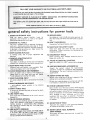
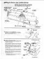
MODEL NO.
]]3.20680
JOINTER/PLANER
ONLY
113.206930
JOINTER!PLANER
WITH
LEGS AND MOTOR
Serial
Number .......................................
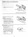
Model and serial
number may be found
on a plate attached
to your infeed table.
CRn MaNo
You should record both
model and serial number
in a safe place for
future use.
6_- INCH JOIN TER- PLANER
CAUTION:
Read GENERAL
and ADDiTiONAL
SAFETY
® assembly
iNSTRUCTiONS
® operating
carefully
Sotd
PartNo.67036
o repair
by SEARS,
ROEBUCK.
AND
parts
CO.,
Chicago,
_t. 60684
U.S.A.
:..........' : : :: ':
FULL ONE YEAR
WARRANTY
ON CRAFTSMAN
JOINTER/PLANER
year from the date of purchase, this Craftsman Jointer/Planer fails due to a defect in material
rs will repair it, free of charge.
,VAtLABLE
BY SIMPLY CONTACTING
THROUGHOUT THE UNITED STATES.
THE NEAREST
SEARS STORE
you may also have other rights which vary from state to
CO,; Sears Tower,
SEARS,
general
safety
the
owner's
application
and
potential
hazards
2.:GROUND
manual
Learn
as the
its
Keep proper
in
proper
adjustment
before
blades,
KEYS
Cluttered
areas
and
must not be Slippery
Provide
adequate
tools
rain;
visitors-should
Consult
work
19: NEVER
space.
i:
AWAY
be kept
a safe distance
from
work
DO not
8. MAKE WORKSHOP
-- with
padlocks,
starter keys,
9. DON'T
or
by
removing
20. CHECK
Before
FORCE TOOL
it will do the job better
it was designed.
10. USE RIGHT
force
designed
switches,
and safer at the rate for which
will
to do
a job
it was not
for.
11. WEAR PROPER APPAREL
Do not
wear
loose
clothing,
gloves,
(rings, wrist
watches}
to get caught
Nonslip
footwear
is recommended.
hair covering
to contain
tong hair.
above the elbow.
12. USE SAFETY
for
as
before
plugging
for
recommended
that accompany
accessories may
ON TOOL
above
is tipped
or near the tool
or if the
such that
to stand on the too_ to reach them.
DAMAGED
PARTS
use of the too!,
should
operate
Check
or attachment
manual
materials
further
is damaged
TOOL
tool
store
such
ACCESSORIES
owner's
STAND
it is necessary
KID-PROOF
master
position
i ::":i Seri0us injury could occur if the toot
cuttin£ tool is accidentally
contacted.
area.
Don't
the
accessories
accessories,
Fol}ow
the instructions
the accessories. The use of improper
cause hazards.
ENVIRONMENT
safest
and
STARTING
is in "OFF"
18. USE RECOMMENDED
Floor
in damp or wet locations
or
Keep work
area well lighted;
surrounding
7. KEEP CHILDREN
All
accidents.
due to wax or sawdust.
6;:!AV01D DANGEROUS
D0n't
use power
expose them
to
invite
best and
lubricating
for
changing
ACCIDENTAL
Make sure switch
in,
CLEAN
benches
for
TOOLS
servicing;
when
bits, cutters, etc.
17. AVOID
Form habit of checking
to see that keys and adjusting
wrenches are removed
from tool before turning
it on.
5: KEEP WORK AREA
at all times,
TOOLS WITH CARE
16. DISCONNECT
and
alignment,
4. REMOVE ADJUSTING
AND WRENCHES
and balance
Keep
tools
sharp
and clean
performance.
Follow
instructions
changing accessories.
IN PLACE
and
footing
15. MAINTAIN
green wire to a live terminal.
order,
fools
14. DON'T OVERREACH
ALL TOOLS
working
power
Use clamps or a vise to hold work when practical
It's
safer than using your hand, frees both hands to operate
tool.
specific
This tool is equipped
with an approved
3.conductor
c0rd and a 3-prong
grounding
type plug to fit the
proper grounding
type receptacle
The green conductor
in the cord is the grounding
wire. Never connect the
in
IL 60684
13. SECURE WORK
carefully.
limitations
as well
peculiar to this tool.
3; KEEP GUARDS
Chicago.
for
instructions
1.:KNOW YOUR POWER TOOL
Read
BSC 41-3.
be carefully
properly
alignment
a guard
and perform
of moving
or other
checked
its intended
parts,
part that
to ensure that
binding
it
function.
of moving
parts, breakage
conditions
that
of parts,
mounting,
and any other
may ,affect its operation.
A guard or
other
is damaged
part
that
should
be properly
repaired
or replaced.
neckties
or jewelry
m moving
parts.
Wear protective
Roll long sleeves
21. DIRECTION
Feed work
of rotation
GOGGLES
OF FEED
into a blade or cutter against
of the blade or cutter only.
22. NEVER LEAVE
UNATTENDED
WearSafety
goggles (must comply with ANS!
Z87.1 )
at all times,; Ats0, use face or dust mask if cutting
operation
is dusty, and ear protectors (plugs or mUffs)
during extended
periods of operation:
Turn power off.
complete
stop.
2
TOOL
Don't
the direction
RUNNING
leave
tool
until
it comes
to a
Safety is a combination Of operator common sense and
alertness at all times when the Jointer-Planer is being used.
9. PROTECTION:
a, ¸
WARNING:
FOR YOUR OWN SAFETY, DO NOT ATTEMPT TO OPERATE YOUR JOINTER-PLANER
UNTIL
IT IS COMPLETELY
ASSEMBLED AND INSTALLED
ACCORDING TO THE INSTRUCTIONS,
.. AND UNTIL
YOU HAVE READ AND UNDERSTOOD THE FOLLOWING,
2. GETTING TO KNOW YOUR JOINTER-PLANER
12
3. BASIC MACHINE
18
OPERATION
4. USE OF HOLD-DOWN/PUSH
5. MAINTENANCE
6. STABILITY
...............
BLOCKS
.........
b.
jointer
is malfunctioning,
has been
Wear safety goggles that comply
with ANSI
Z87.1
and a face shield if operation
is dusty. Wear ear ptugs
or muffs during extended periods of operation.
C_
19
...........................
if any part of your
damaged or broken..,
such as the motor switch, or
other operating
control,
a safety device or the power
cord
. . . cease operating
immediately
until
the
particular
part is properly
repaired or replaced.
PAG E
FOR POWER
2
1. GENERAL SAFETY iNSTRUCTIONS
TOO LS ..................................
EYES, HANDS, FACE, EARS, BODY
d.
Do not plane, joint, or bevel wood shorter than 12
in. Smaller
pieces of wood
can tip over on the
tables, or into the cutterhead
and be kicked back toward you.
Always
use the hold
down/push
block
when
jointing
or beveling wood narrower
than 3 in. but never joint
or bevel wood
narrower than 3/4 in, under any cir-
21
cumstances.
OF MACHINE
Always use the hold down/push
blocks when
wood thinner
than 3 in. but never plane wood
than 1/2 in. under any circumstances.
e.
If there is any tendency
for the Jointer-Planer
to tip
over or move during
certain
operations such as when
planing
or jointing
long
heavy
boards,
the JointerPlaner (stand) should be bolted to the floor.
Avoid
could
awkward
cause a
hand positions,
hand to move
planing
thinner
where a sudden
into the cutters.
slip
7. LOCATION
Never turn your Jointer-Planer
"ON"
before clearing
the table(s)
of all objects (tools, scraps of wood, etc.)
except for the workpiece
and related feed or support
devices for the operation
planned.
g,
The Jointer-Planer
should
be positioned
so neither
operator
nor a casual observer is forced
with the wood while it is being planed.
This
machine
adequate
is intended
for
indoor
to stand
use only.
the
in line
Provide
h.
lighting.
KEEP
8. KICKBACKS
Kickbacks
can cause
serious
injury.
A kickback
when the operator
looses control
of
causing it to be kicked back toward him.
Kickbacks - and possible
avoided by:
injury from
a. Holding
firmly
b.
C,
d,
the workpiece
the
occurs
them can usual]y
against
be
wood
manpieces
cutter
10. Warped wood should
side for best results.
properly,
and cutter
blade
wedge
screws
are
IN PLACE
AND
direc-
OPERAT-
be surface
planed
on the concave
11. To avoid a rough planed surface, determine
if possible,
which way the grain emerges from the wood and feed
the wood accordingly.
Keeping blades sharp. Blades that are dult or nicked
require
more effort
while planing and wilt tend to
pound the wood rather than cut it, which can cause
the wood to kickback.
A nicked blade will cut a ridge in your wood and cause the wood to ride up on the
outfeed
table. Make sure the cutter blades are in-
GUARD
right
Always feed the wood completely
through
the cutter
head and past the cutter guard so that the guard returns to the rest position
against the fence. When
using only one hold down/push
block
to feed the
wood, do not place your other hand on the JointerPlaner.
tables and fence.
Not jointing,
planing,
or beveling
pieces of
smaller than recommended.
(See section in this
ual, "BasicJointer-PIaner
Operations.")
Smaller
of wood can tip over on the tables, or into the
head and can be kicked back toward you.
CUTTER
in the
ING PROPERLY
AT ALL
TIMES.
Regularly
check
the tension
of the cutter
guard spring
to assure
satisfactory
operation.
(See Getting To Know Your
Jointer-Planer
section.)
workpiece
Not taking too deep a cut at one time. A deep cut
requires more effort to feed the wood while planing
and can cause the wood to kickback.
A cut between
1/32 and 1/16 of an inch deep will produce the best
results.
staIted
tight.
Make sure the cutterhead revolves
tion, (toward
the infeed table).
"_'_ GRAIN
12.
/
EMERGING
Do not plane edges of plywood,
composition
materials,
or wood that has glue on it or is painted or varnished.
Planing
these materials
will dul!
the btades
quick!y.
Safety instructions
13,:To be sure you will make adepth of cut as planned,
always lower tl_e infeed table slightly beyond the
depth Wanted. then raise the table to the desireddepth.
for iointer-pQaner
TO BECOME COMMONPLACE.
ALWAYS REMEMBER
THAT
A CARELESS FRACTION OF A SECOND 1S
SUFFICIENT
TO INFLICT SEVERE INJURY.
14. When _aning, jointing, orl beveling wood over four {4)
feet :long, make. sure it is supported at table heig:ht.
t 7.
Readand
ta_!
followthe
15. Never leave the Jointer-Planer work area with the power
on, before the 3ointer-Ptaner has come to a complete
stop; or without removing and storing the switch key.
appearing
on the danger
guard.
DANGER
FOR YOUR
READ
16, Never operate the Jointer-Planer with protective cover
on the unused shaft end of the motor removed.
AND
OWNERS
OWN
FOLLOW
MANUAL
SAFETY
SAFETY
BEFORE
iNSTRUCTIONS
OPERATING
IN
THiS
MA-
CHIME,
WARNING:
THE 2" JOINTER-PLANER
PULLEY AND
THE 2-1/2" MOTOR PULLEY FURNISHED
WILL RUN
THE CUTTER HEAD AT APPROXIMATELY
4300 RPM
WHEN USED WITH A 3450 RPM MOTOR, NEVER
SUBSTITUTE OTHER PULLEYS TO INCREASE THIS
SPEED BECAUSE tT COULD BE DANGEROUS
NEVER
TER
OPERATE
GUARD,
THIS
MACHINE
SLIDING
GUARD
WITH
OR
THE
BELT
CUT-
GUARDS
REMOVED.
NEVER
ER
MAKE
THAN
JOtNTtNG
OR PLANING
CUTS
DEEP-
BLOCKS
FOR
1!16iNCH.
4, ALWAYS
USE
JOINTII_G
WARNING:
DO NOT ALLOW FAMILIARITY
(GAINED
FROM FREQUENT USE OF YOUR JOINTER-PLANER)
WEAR
instructions
on the cutter
HOLD
MATERIAL
OR PLANING
DOWN/PUSH
NARROWER
MATERIAL
THAN
THINNERTHAN
3 INCHES
3 INCHES,
YOUR
The
operat:_or_
of
arw
power
tDo!
car_ result
in foreign
objects
being
thrown
into
the eyes, which
can result in
severe
eye
damage.
Always
wear safety goggles complying
with
ANS_i
Z87.1
(shown on Package) before commencing
power
tool
operation.
Safety Goggles are available at Sears
reta_|
o'rr catalog
storeS.
J
POWER TOOL GUARANTEE
...................
GENERAL SAFETY INSTRUCTIONS FOR
POWER TOOLS .... ...........................
ADDITIONAL
SAF ETY INSTR UCTIONS FOR
JOINTER-PLANER ............................
MOTOR SPECIFICATIONS AND ELECTRICAL
REQUIREMENTS
_. ........
...................
2
.....
i
Cutterblade Sci;ews:..:
:..
;,.:..
3
_ :,::.
Fence
Locks and Stops
:
;.,
i. .....
....
12
12
.......................
12
Scale .............................
13
14
Switch
..............................
JOINTER-PLANER
the Hold
Blocks
Cutter
Sharpening
GENERAL
Cutter
Spring
Blades
MAINTENANCE
DIAGRAM
LUBRICATION
21
Blades .......................
Guard
..................
......................
....................
...........................
ACCESSORIES
REPAIR
..............................
PARTS
23
24
25
25
.........................
RECOMMENDED
21
25
...............................
SHOOTING
19
20
..............................
I r_stalting
18
18
..............
...................................
Cutter
T_OUBLE
...........
.......................
Down/Push
Replacing
WIRING
16
OPERATION
the Workpiece
MAINTENANCE
4
JOINTER-PLANER
......................
14
Beveling
11
........
...............................
Using
8
J]
Fnfeed Table
Feeding
7
i
...............................
BAS_IC
5
5
B
7
UJJ/L
Guard
On-Off
5;
YOUR
of Cut Handwhee!
Cutter
Installing Sliding Guard;. _.....
q;::o:'_:::...:, : ;i ..
E_
Mounting Recommended Craftsman M0torl and
Belt Guards
........
9
Check Motor Rotation..
..... :....... . .. ;, . .... . 10
Jointer-Pulley Belt Guard Instaiiation
TO KNOW
Depth
Fence Tilt
Assembling Steel Legs ; ._
...................
Mounting Jointer-Ptaner On Recommended
Checking
GETTING
Z
Connecting to Power Source Outlet ..............
Check Motor Rotation ........................
UNPACKING AND CHECKING CONTENTS ........
ASSEMBLY .....................
; ............
:
J
................
26
26
27
o
•
_
•
ee
motor spec faCahons and e ectrmcalrequmrements
Th_is machine
is designed
to use a 3450 RPM moto_ only
Do not use any motor
that r._r_s faster' than 3450 RPM,
It is wired for operation
on t10-t20
vo_ts, 60 Hz. _dternating
current.
IT
MUST
NOT
BE CONVERTED
"TO
OPERATE
ON 230 VOI.TS.
EVEN
THOUGH
SOME OF
THE RECOMMENDED
MOTORS
ARE DUAL VOLTAGE,
THESE
CRAFTSMAN
MOTORS
FOUND
TO BE ACCEPTABLE
THIS TOOL.
HAVE BEEN
FOR USE ON
This _x_wer tool
is equipped
with a 3-conductor
cord and
grounding
type plug
which
has a grounding
prong Jisted by
Underwriters'
Laboratories
Association.
The ground
conductor
has _ green
jacket
and is attached
to the tooi
housing
at one
end
and
to the ground
prong
in the
attachment
p)ug at the other end.
This p]u[_ requi:re_s
outJ_t as s.how_l.
if
11/2
1/2
3/4
3/4
3450
3450
3450
3450
110-120
110-!20
t10-120
110-120
12!6
1218
!219
t226
while
you
as showr_
are
mating
pla:n:ning
type
DO
PRONG
an(t
a_ways
3-conductor
to use
for
grounded
this
power
NOT
REMOVE
OR
IN ANY
MANNER.
connect
the
type
tool
is
ALTER
Use an
grounding
!ug
to
k r_c:twn g_ouf_{t.
TO POWER SOURCE OUTLET
This machine
must be grounded
the operator
from electric
shock,
ot_t}et
adat_)te_
CAUTION:
Do not use blower or washing machine motor_
or any motor with an automatic
reset overload protector
as their use may be hazardous.
CONNECTING
the
of the
two
pretty
THE
GROUNDING
a
ip use to
protect
It is recommende(J
that
replace the TWO
prong
THREE
prong out_et:.
you have a qualified
outlet
with a properly
electrician
grounded
An adapter as shown
below
is available for connecting
plugs
to 2-prong _ec{:ptactes,
The green grounding
lug extending
from the adapter must
be connected
to a permanent
ground
s_ch as to a properly
grounded
outlet box.
Plug power cord into a 110-120V
properly
grounded
type
outlet
protected
by a 15.amp,
time delay or CircuitSaw_r
fuse or circuit
breaker.
If you are not sure that your outlet
is propet!¥
have it checked by a qualified
electrician,
WARNING:
DO
g, ounded,
NOT PERIMIT
FINGERS
TO TOUCH
OF PLUGS WHEN
INSTALLING
OR
PLUG TO OR FROM THE OUTLET.
THE TERMINALS
REMOVING
THE
WARNING:
IF NOT
PROPERLY
GROUNDED
THIS
POWER
TOOL CAN _INCUR THE POTENTIAL
HAZARD
OF ELECTRICAL
SHOCK. PARTICULARLY
WHEN USED
IN DAMP LOCATIONS
IN PROXIMITY
TO PLUMBING,
IF AN ELECTRICAL
SHOCK
OCCURS
THERE
ISTHE
POTENTIAL
OF A SECONDARY
HAZARD
SUCH AS
YOU_R HANDS
CONTACTING
THE CUTTING
BLADE.
If power
it replaced
cord
is worn
or cut,
or damaged
immediately.
in any way,
have
NOTE: The adapter
illustrated
is for use only if you already
have a properW
grounded
2-prong
receptacle.
The use of any extension
cord will ,cause some loss of
power. To keep this
to a minimum
and to prevent
overheating and motor
burn-out,
use the table below to determitre the mirdmtjm
wire
size (A.W.G.) extension
cord. Use
only 3 wire extension
type plugs and 3-pole
plug.
Extensior_
Cord
Up to 1OO
!00
200
200-400
3-PRONG
PLUG
GROUNDED
PROPERLY
i
J
MOTOR
Length
have 3-prong grounding
which accept the too&
Wire
Size
A,W.G,
Ft.
14
Ft,
!2
Ft.
8
ROTATION
WARNING:
FOR
YOUR
OWN SAFETY,
MAKE
PLUG tS NOT CONNECTED
TO POWER SOURCE
LET WHEN CHA_%IGtNG
MOTOR
ROTATION.
__
OUTLET.,_
CHECK
cords which
receptacles
@
GROUNDING
PRONG
SURE
OUT
The
mote."
must
rotate
COUNTERCLOCKWISE
whet
viewed from the s_qaft enci _o which
you wil! mount
th_
pu!_ey, (See page 1'O). _tf it does not, change the dire_,:._ior
acco_-diqg to the ir;structions
furnished
with the motor.
Combination
:
3/4,:'Wrench
: :
:_. :.
:3/8_,Wrench
: :::i: :
: i:::i: :
::_ : _
Model
t13.20680
'one. cartOn, but
motori
.....
.......
JointeriPlaner
iS shipped
¢_mplete
DOES NOT
INCLUDE
Stee|
Legs.
.....
......
Model
t13.206930
Jointer/Planer
one carton but INCLUDES
Steel
in
or
in
each
make
any
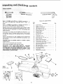
If any parts are missing, do not atternPt:t
O assemble
the
jointeriplaner,
plug '_n the power Cord Or turner
the
switch
On until
the missing parts are obtained:and
are
installed
correctly.
Remove the protective
oil that
metal 'surfaces. Use any ordinary
spot remover.
Apply
use gasoline,:
a coat of automobile
Wip e all parts thoroughly
is applied to, e!li :unpainted
household! type
grease
and
naptha
or
similar
highly
wax to the table.
with
a clean_ dry cioth.
WARNING:
....:
:
FOR
:CONNECT
PLUG TO POWER :SOURCEOUTLET
'ALL
ASSEMBLY
STEPS ARE COMPLETE,
TABLE
NEVER
U:NTIL
AND
YOU
OF LOOSE
PARTS
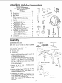
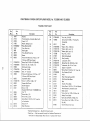
Item
No.
is shipped
comp!lete
Legs, and Motor.
Separate
all: parts from packing
materials :and check
one with the illustration
and the list of Loose Parts
to
certain all items are accounted
for, before
discarding
packing material.
CAUTION:
Never
::volatile solvents.
Square
Description
Qty.
A
B
C
D
E
F
G
Jointer-Planer
......................
V-Belt, t/2 x 52"
. ..................
5/32 Setscrew Wrench
................
t/8 Setscrew Wrench
.................
Motor Pulley, 2-1/2 °" Dia ..............
Sliding Guard Knob
..................
Concave Washer .....................
1
t
1
1
1
t
2
H
J
K
L
M
N
O
Sliding Guard
......................
Sliding Guard Rod ...................
Nut, 1/2 - t3
.......................
Lockwasher,
1/2
....................
Lockwasher,
No. 10
.................
Screw, Pan Hd. t0 - 32 x t/4
..........
Owners Manual
.....................
1
1
1
t
2
2
1
P
Q
R
Depth of Cut Handwheel
..............
Screw, Sems, t/4 - 20 x 1-1/4
..........
Jointer-Planer
Belt Guard
.............
!
1
1
S
T
U
V
W
X
Y
Z
Attaching
Hardware
(2 Nuts, 2 Bolts)
Motor Pulley Belt Guard
..............
Belt Guard Clips
....................
Belt Guard Support Bracket
...........
Belt Guard Support
..................
2 self tapping screws
Switch Key
........................
Hold Down/Push
Block
...............
1
3
t
1
1
2
0
:: V
unpacking
Qnd checking contents
TABLE
OF LOOSE
PARTS
Item
The Following Parts Are
Model 113.206930
No.
Description
A
B
C
D
E
Included With
Only
Qty.
Leg ..............................
End Stiffener
........................
Side Stiffener
......................
Motor Support
.....................
Motor
............................
4
2
4
!
I
Package of Miscellaneous
Small Parts,
No. 67035, Consisting of the Following:
F
G
L
Cord Clip ..........................
Hex Nut, 1/4 in. - 20
(approx. dia. of hole 1/4 in.) ..........
Hex Nut, 5/16 in. - 18
(approx. alia. of hole 5/1 6 in.) .........
Hex Nut, 1/2 in. - 13
(approx. dia. of hole 1/2 in.) ..........
Truss Hd. Screw, 1/4 in. - 20 x 5/8 in.
tong. (Top of screw is rounded)
........
Flat Washer (dia. of hole 11/32 in.) ......
Lockwasher,
1/4 in. External
Type
(approx. alia. of hole t/4 in.) ..........
Lockwasher,
5/16 in. Externa_ Type
(approx. dia. of hole 5/16 in.) .........
Carriage Bolt, 5i16in.18x3/4tong
...
M
N
Leveling Foot
Hex Hd. Screw,
G
G
H
J
K
K
......................
5/16 in. - 18x
2
40
E
F
7
8
40
7
G
H
©
40
7
3
K
4
3
2in .....
L
M
ill
,
i
ill
i
assembly
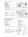
ASSEMBLING
TRUSS HD. SCREW
1/4-20 x 5/8
STEEL LEGS
NOTE:
Steel Legs are furnished
with
Model 113.206930.
From among the loose parts, find the following
Hardware:
40 Truss Head Screws,
1/4-20
40 Lockwashers, 1/4-External
40 Hex Nuts, 1/4-20
8
Hex Nuts, 1/2-t3
4
Leveling Feet
LOCKWASHER
1/4 EXTERNAl-
END
STIFFENER
x 5/8
END STIFFENER
.....
1/4-20
HEX
IDE STIFFENERS
1. Assemble two (2) Side Stiffeners
together using four (4)
1/4-20 Truss head screws, Iockwasher
and nuts. Make
two (2) Side Stiffener
assemblies.
The End Stiffeners
are placed on top and at each end of
Side Stiffener
assemblies
as shown. Atign holes, tetter
coded "B °' in Side Stiffeners
and End Stiffeners
and
then insert t/4-20
Truss head screws through the 9/32
diameter
holes letter coded
and nuts and then tighte_n.
2. Assemble
the
Stiffeners
shown,
using
four
(4)
t/4-20
"C"
and install
"i'"_J
Legs
screws,
to
the
Side
and
End
Legs with
Support
These
adjustment.
levelers
are
/
not
intended
°
SUPPORT
_i
_
i
_i
E
'i
t/4-20
can be
f
Install leveting feet as shown. To level Leg Set, loosen
nut on inside of leg and tL_rn nut on the outside to raise
or lower feet. Adjust
all four leveling feet, if necessary,
and then tighten
nuts o_ the inside of leg.
NOTE:
MOTOR
lockwashers and nuts as
3. Assemble
the Motor Support
to the
screws, lockwashers
and nuts.
Motor
assembled to either end of Leg set.
4.
lockwashers
for
height
LEGS
'i
LEGS
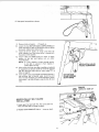
MOUNTING
JOINTER:PLANER
the
following
____
hardware:4 Carriage 8ott,: 5./16_18 x 3/41
3 Hex Head: screws,: 5/16_18 X:2
7 Lockwashers,
5/i6
in. EXternal
HEAD
JO INTER/PLANER
SCREW
Type
7 Washers, 11t32 1D
7 Hex Llam Nuts, 5/16-18
2 Cord Clips
STIFFENER
t. Loosen FENCE LOCK KNOB.
slide it toward the pulley.
Tilt
fence upward and
HEX
NUT W
2. PoSition machine on Leg Set and align mounting
holes in
machine with holes in Leg Set letter coded °'A'. Mount
with three (3) 5/1 6-18 x 2" Long Hex Head Screws.
FENCE LOCK
KNOB
,\
3. Place a flat washer, a lock washer and a nut on each
screw from underneath the stand and tighten.
4. PlaCe handwheet
on shaft aligning
with
flat surfaces on handwheel..,
screw.
flat surfaces
attach with
H
1-1/4 IN. SCREW
on shaft
1-1/4 in.
t
I
1/4-20 TRUSS
HEAD SCREW
I
SIDE STIFFENER
1
DEPTH OF CUT
HANDWHEEL
/
.,_MOTOR
SUPPORT
AT THIS
END ----_
J
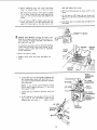
CHECK! NG CUTTER
BLADES
OUTFEED
TOOLS
5/32 IN. SETSCREW
WRENCH
AND SCR EWS
TABLE
NEEDED
5/32"
Jointer),
and
1/8"
Setscrew
Wrenches
WEDGE
with
(furnished
Lead Pencil
Short straight
1. Insert
pencil
cutterhead
2.
edge (or head of combination
in space
at
end
of
square)
cutterhead
to
hold
of
Cut
guard open.
Lower
the
Handwheet.
infeed
table
with
the
Depth
3. Rest the straight edge on edge on the surface of outfeed
table so it extends
across the opening
between
the
tables,
middle
4.
at three positions:
of the cutter blade_
near
each
end
and at
the
ROtate the cutterhead
by grasping
the 2" dia. driven
pulley and make-sure
each knife
ticks
(touches)
the
straight
edge at all
three
positions.
If not,
follow
procedure
under "REPLACING
CUTTER
BLADES"
on
ppg. 21 and 22.
PENCI
L
CUTTER GUARD
5. If a cutter blade adjustment
is not required,
check each
locking:
screw of each wedge (5/32"
setscrew wrench)
and
tighten
if
necessary.
Hold
the
pulley
while
tightening
screws and be careful that your fingers do not
slip off the wrench."
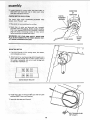
iNSTALLING
SLIDING
GUARD
1/2 IN. HEX NUT
PARTS NEEDED
1
Sliding
I
t
2
1
Sliding Guard Knob
Sliding Guard Rod
Sliding Guard Washers (one side of washer
Hex. Nut 1/2 in.* t3
Guard
1
2
Sl_it lockwasher
1/2 in.
E×t, tooth Iockwashers
2
10-32xl/4
Pan Hd. Screws
t.
Screw
alt the
nut
1/2 in. lockwasher
way
is concave)
SLIDING GUARD
onto
long
end of rod..
, place
next to nut.
2. Screw rod all the way into Jointer
tighten nut.
with
short end up...
SLIDING GUARD
10-32xl/4
3, Attach
sliding
guard
and lockwashers,
to fence with
Guard
two
machine
screws
4.
Place one Sliding
support rod.
Washer, concave side DOWN
5.
Drop sliding guard onto rod..,
place other washer, concave side UP on rod , , . screw on Sliding Guard Knob,
MOUNTING
RECOMMENDED
MOTOR AND BELT GUARDS
See page 5
for
recommended
Planer
5]16-18
3/4
SCREWS
on
CRAFTSMAN
motors.
x
WASHE R
(CONCAVE SIDE UP)
EXT. TOOTH
LOCKWASHERS
PARTS NEEDED
4 carriage
bolts,
washers and nuts.
KNOB
in.,
flat
washers,
lock
3
1
1
2
Belt Guard Clips
Motor Pulley, 2-t/2 in. dia.
V-Belt
Pan Head Screws 10 - 32 x t/2
2
2
Hex, Hd. Screws 1/4 - 20 x 1/2 in.
Hex, Nuts 1/4- 20
in,
TOOLS NEEDED
1
Jointer
Belt Guard
1
1
!
Motor Pulley Belt Guard
Belt Guard Support
Belt Guard Support
Bracket
Medium Screwdriver
5/32 in. Setscrew Wrench (furnished
1/2 and 7/!6 in, Wrenches
5/:8 IN. DIA,
with
Jointer)
SHAFT
PAN HD. SCREWS
1, Place motor on your workbench
(with key way) facing you.
2. Attach
guard
support
to
with
bracket
5/8 in. dia, shaft
with
two
screws.
NOTE:
The holes in the bracket are not threaded,
but
the screws are "thread
cutting
screws" and win cut a
thread as they are tightened,
BELT
GUARD
SUPPORT
BRACKET
BELT
GUARD
SUPPORT
9
¸
• ':
C_i _:!:iin:motoK pdiley and:place:Pulley:iOn
h_ f|U_h:! _itt+ end i:
sfiaf_ii ihSertl motif:r:
DIRECTION
OF
ROTATION
5/32 IN.
SETSCREW
WRENCH
The motor rn_:$
_iewed from +PULLEY
\
end:
1_ Place m0tor on your workbench or on floor.
2. Stand clear of motor and plug cord into a properly
grounded outlet (See page 5). Notice rotation of pulley,
If it is:not= turning COUNTERCLOCKWISE,
REMOVE
plug from outlet, and change rotation of motor according to instructiOns furnished with motor;
WARNING:
FOR YOUR OWN SAFETY, MAKE SURE
PLUG iS NOT CONNECTED TO POWER SOURCE OUTLET WHEN CHANGING ROTATION.
MOUNTING
MOTOR
FLUSH
HERE
SHAFT
KEY
@
MOTOR
1. Find four 5/16_t8 x 3/4"
and lockwasher and nuts.
carriage bolts, flat washers,
2, Attach motor by inserting carriage bolts through slots in
motor base and through slots in motor support. Place a
fiat washer, 10ckwasher and nut on each carriage bolt,
but DO NO:F TIGHTEN nut.
I
==
MOTOR
::;1
MOUNT
BRACKET
.....
j
,
BELT
6, Install three clips on belt guard 90 ° apart with long tabs
pointing AWAY from round opening.
7, Insert belt into open end of guard,
/
_*_BELT
GUARD CLIPS
(90 ° APART)
10
8. Snap guard
9.
10.
into
Remove
position
knob
as shown.
and washer..,
lift guard
up.
Loosen the two MOTOR
BASE CLAMP SCREWS and
rotate the motor so that the ventilation
slots are facing
downward,
tighten
base clamp
screws.
11.
Install
the 2_t/2 "' pulley
on motor
and move the
motor sideways until the motor pulley is aligned with
the pulley on the machine.
12.
Install
tension
V-Belt
and PUSH down on
to the
belt
and tighten
mounting
NOTE:
13,
After
bolts.
it is only necessary to apply enough
tension
to the belt to prevent
it from
sJipping in
pulleys while running.
motor
and V-belt
have been installed
for alignment
and tension
Leg Set using the holes
shown on page 8.
14.
motor
to apply
nuts
on motor
VENTILATION
HOLES
FACING DOWNWARD
and adjusted
install the metal belt guard to
that are letter coded "B" as
Insert motor cord plug through rectangular
opening in
side stiffener
that is directly
under switch
box and
then into the receptacle.
To prevent damage to motor
cord attach it to side stiffeners
using the two (2) cord
MOTOR BASE
CLAMP SCREWS
(BOTH ENDS)
clips.
...
JOINTER-PULLEY
INSTALLATION
,
i,
ii
iI'M_'II'
I
I'1
WASH ER
(CONCAVE
BELT GUARD
I. Attach guard to stand with Hex. Hd. screws and nuts.
Make sure belt does not scrape on guard.
2. Replace washer
CONCAVE
side up.,.
BOLT.
screw on knob,
NUT
!i
SIDE UP)
i ¸
•
know
:Q
•
••
:•••
•
•
our
.... olnter....
Pmaner
WARNING:
F_R" YOUR
OWN: SAFETY
TURN SWITCH
2
SLIDING
GUARD
INFEED
TABLE
SLIDE
BRACKET
I
\
CUTTER GUARD
IIII
!
_1
L
6
DEPTH OF CUT
HANDWHEEL
ON-OFF
SWITCH
|1,, 11 i
I
....
1
_
i
INFEED
//_
DEPTH OF CUT
_-_-../TABLE/j
_
HANDWHEEL
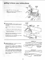
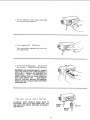
11: DEPTH OF CUT HANDWHEEL.
Turning the
handwheel counterclockwise Will lower the infeed
table to maximum depth of 1/8 in,
f
_.. FENCE
/
SLIDING
LOCKS AND STOPS. The fence can be
GUARD
moved across the Jointer to take full advantage of the
"sharpness" of the blades.
PUSH DOWN
WHEN LOCKING
FENCE LOCK KNOB
The:fence should be positioned to the extreme right
(toward pulley) but not beyond the end of the blades.
FENCE
Mostof the cutting (usually jointing) witl be done with
the fence in this position.
As the blades become dull,
the fence can be moved toward
the left where the
45°FENCE
STOP
blades are sharper.
To move the fence,
the Sliding
loosen the Fence
Gu_ird Knob
Lock Knob
and
90 ° FEN,
STOP
and slide to desired position.
Make sure SLIDE
BRACKET
is even with surface of
OUTFEEDTABLE.
If it is above or below the surface,
loosen screws and adjust it.
a. Alwavstighten
fence Iock knob first to align fence,
then tighten sliding guard knob.
FENCE
KNOB
1:2
\
\
SLIDE BRACKET
KNOB
b. Before
down
tightening
on outfeed
lock
knob, hold
so it does
not
fence square to tables.
two knobs .and pull the
angle and tighten
both
d. To
tables,
set
fence
at 90 °
to
fence so t;qe stop
fence back so the
loosen
::
fence
rock.
c. 90 ° Fence Stop positions
To tilt fence, loosen the
sto;p out. Tilt
to desired
knobs.
knobs,
tilt
place. Tilt
. .
fence
table
the
e. 45 ° Fence Stop
tables.
f.
To
tilt
fence
both
knobs,
positions
to 45 °
90 ° stop out, tilt
table
the fence at 45 ° to the
loosen
the
two
knobs,
pull
fence so the 45 ° stop rests on the
two
g. Hold fence down on outfeed table and tighten the
two knobs.
springs back iSto
stop rests on the
:....
table: ahcl tighten
i iiiiitJ:IH111111
i!i_
. FENCE TILT
fence
to
the
TILT
SCALE
SCALE.
tables.
rectly adjusted,
the scale wi]l
FENCE
indicates
the angle of the
When the 90 ° fence stop is cor-
900 FENCE
the fence wilt be 90 ° to the table and
read 90 ° .
To check for squareness, place
infeed
table and check fence
an accurate square on
while locked
at 90 °
position.
MAKE
SURE
SLIDE
BRACKET.
STOP
90 °
IS
STOP
_
SQUARE
AGAINST
INFEED
TABLE
FENCE
FACE
if fence is not square to table;
a, Slightly
knob.
loosen
fence
lock
knob
and
guard
lock
CUTTER
GUARD
b_
SCALE
ADJUSTING
SCREW
Loosen 90 ° stop screw with small screwdriver
and
turn knurled
sleeve which will cause fence to tilt.
Turn sleeve in either direction
until fence is square
with infeed table.
45 ° STOP \
NOTE:
knurled
90°STOP
If you
cannot
square fence
sleeve, loosen three screws "A"
LOCKSCREW
• _
by turning
and adjust
TILT
/SCALE
fence square to table.
c.
d,
Tighten
knobs.
If
90 °
90° stop tockscrew and both fence lock
reading
on tilt
scale does not
line
_90 °
STOP
•,._ SCALE
up with
top surface
of the slide bracket,
_oosen screws
holding
scale and move it . . . tighten
screws.
-_ ADJUSTING
A
_
45 ° STOP
KNURLED
900STOp
t3
1
SLIDE
BRACKET
SCREW
tO know
your I'Ointer-manet
..... P
FENCE
::e.
Adjust
450
stop
in
the
same
CUTTER
GUARD.
cutter head. It must
ing properly.
Check
perly.
adjustment
protection
over
if it
fence to
the
be in place and function-
make
right
sure it iS functioning
for maximum
width
pro-
of cut.
b. Pass al/4
in. thick piece of wood
between quard and fence.
over cutterhead
Guard must return automatically
to
against fence When free of the wo0d:
"rest
If guard'does
Shooting
and
CUTTER
GUARD
FENCE
the. guard to
a. Posi.tion
Provides
always
INFEED
TABLE
manner.
NOTE:
Tilt scale will not require
was= adjusted foi _ 90 ° position.
4,
HEAD
OF
SQUARE
\
not return
Maintenance
automatically,
Sections.
INFEED TABLE
position"
see Trouble
CROWNED CUT
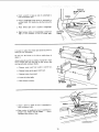
_.
INFEEDTABLE:MUST
LEL TO THE OUTFEED
ALWAYS
TABLE.
BE PARAL-
If the cut edge or surface
of the workpiece
is
CROWNED,
it is an indication
that the OUTWARD
END of the INFEED
table
is HIGH
and must be
INFEED
"_"-__
TABLE
END
HIGH
TABLE
LOW
adjusted.
:
..... :, If the cut edge or surface of the workpiece
is CON:
CAVE, it is an indication
that the OUTWARD
END
of the INFEED
table is LOW and must be adjusted.
_:
: :Check
the infeed
table
to
determine
the:
"out
CONCAVE
CUT
of
INFEED
'
14
:!:'/i_I_:i__:i?_i;
_:_:::' :::i,_::: i: :_:_
::i:/
::ii:
:!;_:i::::}::i_
I:_i_:_:/!:
:: : ::
ROTATE
BLADE
OUT OF
Insert a pencit in space at end of cutterhead
hold cutterguard open.
a.
Place a straightedge
outfeed
table. First
other.
b,
c. Raise
d,
infeed
Sight
high
table
between
or low
WA /
to
PENCIL
/
__
(large square or tong level) on
along one side than along the
until
it touches
table and straightedge
condition
of end of
straightedge.
to determine
infeed
table.
OU
FEED
"___-__._._
TABLE_
It is easier to adjust the infeed
setting on your workbench.
Do not turn
adjust it.
the Jointer
table while
the Jointer
on its side or upside
is
down to
Attach a strip of wood to two blocks of wood 10 in. high.
Drive enough
nails into the strip so that Jointer
does
not tip over while resting on blocks.
a. Remove
motor
cord
from
b. Remove
Jointer
pulley
guard and V-belt.
c.
Remove Jointer
d. Lower
from
the infeed
e, Place Jointer
outlet
in switch
box.
stand.
table,
on blocks.
YOUR WORK
BENCH
f.
Insert
hold
a pencil
cutterguard
in space at end of
cutterhead
to
open.
g, Wrap a piece of cardboard
around
cutterhead
to
protect
your fingers and the blades , . . secure
cardboard
with a piece of tape.
CARDBOARD"
15
toknow:
:':i_:_
::
. ........ .....
your io nter planer
:
L0osen foUr:ioCk Screws 2:or: 3 turns with 1/2 in.
Wrench;
LEVELING
STUDS
I
LOCKSCREWS
VIEW LOOKING UP FOR PARTS IDENTIFICATION
Turning the' LEVELING
the infeed table.
STUDS will RAISE or LOWER
SCREWING
in the studs will RAISE the table . . .
UNSCREWING them will LOWER the table.
a, With: a 3/4 in. wrench
turn leveling
infeed table is parallel with straightedge.
studs until
b; While: holding studs with wrench, TIGHTEN all
four LOCKSCREWS...
tighten each screw a little
bit =at _:a time Until all four screws are:::itight;
_. RecheCk with straightedge to make sure infeed
table is parallel to outfeed table.
6.
ON-OFF
SWITCH:
It is unlikely that it wiff be
turne_ "ON" accidentally, when touched or bumped,
because of the way it is shaped.
In an emergency, it can be turned "OFF"
it with the palm of the hand.
by striking
The "yellow
button"
is a key. When inserted in the
switch lever, the power may be turned ON and OFF.
When it is removed, the power cannot be turned ON.
THIS FEATURE
UNAUTHORIZED
HAZARDOUS
OTH ERS.
IS INTENDED
TO PREVENT
AND
POSSIBLE
USE
BY CHILDREN
AND
KEY
a, Insert Key into switch.
NOTE:
Key is made of yellow plastic.
16
_i ! i::
b, To turn machine
on, insert finger
lever and pull end of switch out.
c, To turn
Never
machine
OFF...
leave machine
to a complete
under
!_
i
switch
PUSH lever in,
unattended
until
it has come
stop.
d. To lock switch in OFF position,,,
hold switch
IN
with one hand...
REMOVE
key with other hand.
WARNING:
FOR YOUR OWN SAFETY, ALWAYS
LOCK THE SWITCH "'OFF" WHEN MACHINE IS
NOT IN USE . . . REMOVE KEY AND KEEP tT IN
A SAFE PLACE ... ALSO . . . IN THE EVENT OF A
POWER FAILURE
(ALL OF YOUR LIGHTS GO
OUT) TURN SWITCH OFF . .. AND REMOVE
THE KEY. THIS WILL PREVENT THE MACHINE
FROM STARTING UP AGAIN WHEN THE POWER
COMES BACK ON.
e. Plug
motor
cord
into
outlet
in
switch
box.
WARNING:
DON'T CONNECT
POWER CORD TO
ELECTRICAL
OUTLET IN YOUR SHOP UNTIL YOU
ARE SURE THAT MOTOR ROTATION
IS CORRECT,
(SEE PAGE 10).
OUTLET
CORD
CORD
17
_i -_ • • - ,.,
being
tables
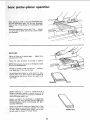
For your own safetY:, ALWAYS use the hold down/push
bi0cks.when JOiN_lNGw0od
thai_ is NARROWER than
3in.. !:.o_ whenP LANt NG:w00d: that is THIN NE R than
3 in:
Do not
Material
plane, joint
this short
0r bevel wood shorter
than
is more difficult
to control
cut. Small
pieces of wood
can tip over on the
or into the cutterhead
and can be kicked back to-
ward you.
For best results, take light cuts. For average
jointing,
or beveling,
a cut between
1/32 and
12 in,
while
deep will
produce
the
planing,
1/16 in,
best results.
5
-!
ii
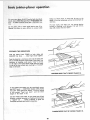
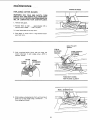
FEEDING
Hold
the
AGAINST
THE WORKPIECE
board
firmly
DOWN
on both
tables and
the fence . . . keep fingers close together.
!i
Feed the board at a continuous
even rate of speed until
the cut is made along the entire length of the board. Any
hesitation
or stopping could cause a "step"
to be cut
on the edge of the board which would cause the board
to ride Up on the outfeed
table resulting
in.a "crooked'"
edge on the board,
JOINTING
WOOD
THAT
IS WIDER
PLANING
WOOD
THAT
IS THICKER
THAN
3 IN,
As the RIGHT
hand passes over the cutterhead,
remove
the LEFT
hand,
. , CONTINUE
feeding white placing
the LEFT
hand behind the RIGHT,
Continue
feeding
in this manner
"hand
over hand",
until the entire
length
of
the
board
is cut.
DO NOT FEED TOO FAST. A slow steady rate of feed
produces a smooth accurate cut. Feeding too fast causes
a "rippled"
cut . . . makes it difficult to guide the
workpiece accurately and could be hazardous.
18
THAN
3 IN.
:
:_ _:_ i_
_: ,i
:
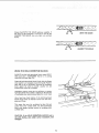
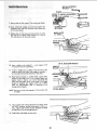
Always feed WITH THE GRAIN whenever possible. If
the nature of the workpiece is such that it must be fed
AGAli_ST THE GRAIN, take very light cuts and feed
slowly.
WITH THE GRAIN
AGAINST
USING THE HOLD DOWN/PUSH
ALWAYS
use the hold down/push
ING wood that is NARROWER
wood that is thinner than 3 in.
Grasp the hold down/push
BLOCKS
blocks when JOINTthan 3 in, or planing
blocks
firmly
with
the fingers
close together
and wrapped around the handle. Position
them flat on top of workpiece,
and push the workpiece
down
against the table to provide
a quality
cut and
minimize
the chance of a kickback,
Hold-down
pressure must also be sufficient
to prevent
hold-down/push
block sliding or slipping on the top face
of workpiece when advancing workpiece over cutter head.
Use a hand
over
hand
blocks being careful
piece at all times.
motion
to maintain
of
the hold
control
down/push
over the work-
This means that once the workpiece
has been fed past
cutter
head onto outfeed
table, one hold down/push
block must always maintain
contact of workpiece
with
outfeed
table,
CAUTION:
if the HOLD DOWN/PUSH
slip while feeding,
sandpaper.
BLOCKS tend to
clean rubber surface immediately with
19
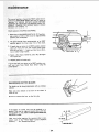
THE GRAIN
when pianing wood 3/4 in, thick and NARROWER
than
the holdldownipush
b!ock_ tilt the
h0td d0wn/push
block so that it clea_s"the top of the cutterguard
while
#eeding.
Never plane wood that is thinner than 1/2 in....
because
it }s apt. to split or:Shatter and thus has a greater tendency to kickback,
LILLL_'L"
I I
II m
I
I
I
I
I=ml
I'L
BEVELING
Adjust
the fence to the desired
and guard lock knobs.
Follow
the
same
procedure
angle
for
. . . tighten
jointing
or
fence
planing.
_ i::' NOTE: Removing only the corner on the edge of a board
is known as CHAMFERING.
Normally a chamfer is made with one cut..,
a cut deeper than t/16 in. may be made_
therefore,
Use hold down/push blocks for wood under 3 in, wide.
Position them so you have control of the workpiece at
all times and so they do not contact the guard orthe
cutter head,
CHAMFER
BEVEL
NOTE: Rabbeting on a Jointer is consid_.red to be a
dangerous operation because it requires removal of the
cutter guard and increases the potential of kickback because of excessive depth of cut.
,//
•
, i¸
:
:=:
:
NEVER ATTEMPT
TO PERFORM A RABBETING
OPERATION ON THIS JOINTER, DO NOTOPERATE
JOINTER/P[ANER
WITH CUTTERHEAD
OR BELT
GUARDS REMOVED.
Rabbet cuts should be made on the Radial Saw or Table
Saw by making two cuts with the sawblade or by using
the Dado Head or Molding
Head. Rabbet cuts can also
: be made using the Shaper or Portable
Router.
i
i
••
RABBET CUT
•2o
!
rnainfenance
BLOCK
REPLACING
CUTTER
!.
j-
BLADES
WARNING:FOR
YOUR OWN SAFETY.
TURN
SWITCH "OFF"AND
REMOVE PLUG FROM POWER
SOURCE OUTLET BEFORE ADJUSTING, MAINTAINING, OR LUBRICATING
YOUR JOINTER-PLANER.
t.
OF WOOD
Remove belt guard.
2. Position fence to right . . . approximately
beyond cutter blades , , . lock it in pDace.
3.
Lower infeed table
4.
Place block of wood
guard and tence.
114 in.
all the way down.
6-3/4
in.
long
between
cutter-
HOLD PULLEY
FIRMLY
5/32 IN.
SETSCREW
5. Hold
cutterhead
loosen lockscrews
setscrew wrench,
pulley
firmly
with one hand and
in each wedge using a 5/32 in,
BLADE
L! FTE R
SCREW
WRENCH
TURN COUNTER
CLOCKWISE
WEDGE
LOCKSCR EW
WEDGE
FENCE NOT SHOWN
FOR PICTURE CLARITY
SMALL SCREWDRIVER
6. While holding cutterhead
pulley firmly with one hand,
gently pry up each wedge using a screwdriver,
. . remove wedges and blades.
21
maintenance
7*: Remove
=
:the six lifter
5/32 IN. SETSCREW:
WRENCH
screwsi (Two
under each blade.)
CUTTER HEAD i
SETSC R EW
8_ C!ean cutterhead,:wedges and screws thoroughly with
craftsman Gum and Pitch Rem0ver. A!_o remove the
oil from dew blades,
MARK SLOTS
9; Replace the six lifter screws and screw them in all the
way, but do not tighten. Mark each slot 1, 2, and 3.
This will help you in setting the blades.
1/8 IN. SETSCREW WRENCH
10.
Insert a blade
in. beyond
1"[
¸.
in slot marked
endof
1 ...
so it projects
1/16
HEAD OF
SQUARE
the Cutterhead.
\
"Insert a wedge next to blade so the flat side of the
wedge i's again'stthe blade. Pushwedge in manually
do not instal! tw0 locking setscrewsat this time."
TABLE
Place:head:of
square on outfeed table. LooSen lifter
screws to raise blade until it just touches square and
s ghty
raises
forth
with:the
should
table,
it: Gently
turn cutter
head back and
pulley while raising blade. The blades
be adjusted
just
by approximately
slightly
above the:
.003
in, (thickness
outfeed
of an
average piece Of paper).
LIFTER
NOTE: Sears has a knife setting gauge for this purpose. Cat.
# 9-2647
13. "Now install both locking setscrews and tighten (with
the 5/32" setscrew wrench) alternately a little at a
time. Tighten both screws securely. Recheck the blade
to make sure it did not change position."
14; Install other two blades the same way;
22
SCREW
INSTALLING
1.
Remove
remove
CUTTER
cotter
guard
Spring must appear
feed table,
it will
upside down.
pin from
(located
GUARD
SPRING
pivot pin in cutter guard and
underneath
infeed table.)
as in sketch
not perform
from underside
of inproperly
if installed
VIEW LOOKING UP
FENCE
IN PLACE
1. Position guard as shown,
in infeed table.
2. Atign SLOT
down.
3.
Replace
cotter
with
PIVOT
in pin with TANG
CUTTER
GUARD
PiN above hole
in spring, and press
TANG OF SPRING
IN CENTER OF
HOLE
pin,
LIFT
FENCE
4. RAISE end of FENCE, rotate guard COUNTER
clockwise only enough to CLEAR fence.
5.
LOWER
fence and tighten
both knobs.
COUNTER
CLOCKWISE
23
The normal position of guard {at REST) when fence is
Stati0nedat MAXIMUM
WIDTH OF CUT; is shown as
........
•.....
postlon
A
NEVER ROTATE GUARD B EY O ND
POS|TION"B"
BECAUSE THIS WOULD EXERT EXCESSIVE TENSION
ON SPRING
WHICH COULD
WEAKEN OR BREAK
IT,
Check
Operation
1:_ With fence
of GUARD
and SPRING.
in MAXIMUM
WIDTH
pass a piece of 1/4 in. thick
position)
over cutterhead.
OF CUT
wood
position,
on edge (jointing
'
2. The guard should return
a_tomatically
to its REST
position
against the fence when free of the wood.
3.
_.L
If guard does not return to its REST position,
remove
cotter pin from
pivot pin and remove guard. Check
pivot pi_n and hole..,
make sure there are no burrs,
rust, or other foreign matter.
4. Apply
a few drops
0il to pivot pin.
5.
Replace
of SAE
guard and cotter
No.
,,
POSITION
20 or No. 30 engine
p_n.
If guard still does not return to its REST position,
consult your
local Sears Retail
Store before
using the
jointer-planer,
,
i
=ll
SHARPENING:
The
blades
,i
i
CUTTER
can be honed
i
,
i
i
ii
BLADES
individually
with
an ordinary
is not
in the
oilstone,
Make sure your
must be flat.
Be sure to
oilstone
remove
the
burr
worn
on the
flat
center.
It
side.
If the blades are nicked, they must be replaced or reground; They can be reground several: times until they
become 9/16 in. wide. Never install reground blades less
than 9/16 in. wide.
Have
your
petent.
Look
directory
...
knives
reground
in the "YeI|ow
see "Sharpening
by
someone
who
is corn *
11116 IN.
Pages" of you r telephone
Services"
NEWBLADE
24
"B"/
/
OF
generaB maintenance
Keep your jointer-planer
clean. Put a carton or some kind
of a container
underneath
your iointer-ptaner
to catch
the chips. The container
should reach above the top of
the motor.
Do not allow
pitch to accumulate
fence, the cutter guard, the cutter
Clean them with
Craftsman
Gum
Do not aflow chips to accumulate
jointer-planer.
Frequently
blow
side the motor.
on the tables, the
head or the knives.
and Pitch Remover.
For motor
with motor.
Apply a thin coat of automobile-type
wax to the tables
and fence so that the wood slides easily while feeding.
out
on the underside
any dust that
maintenance,
follow
of the
may accumulate
instructions
If power cord is worn or cut, or damaged
have it replaced immediately.
in-
furnished
in any way,
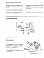
wiring diagram
MOTOR
OUTLET
-SWITCH
WHITE
"-'__
- _
I
Insulated
Cap, Flag
GREEI'4
J
J_
Iubricaffon
The BALL
BEARINGS
in this
machine
grease at the factory.
They require
The following
parts
SAE No. 20 or No.
should be oiled
30 engine oil.
1. Dovetail
spacer
and dovetail
are packed
no further
with
lubrication.
occasionafly
with
slide.
DOVETAt
L
SPACER AND
2. Elevating screw (first clean with Craftsman Gum and
Pitch Remover).
SLIDE
ELEVATING
SCREW
'i
VIEW LOOKING UP FOR
PARTS iDENTIFiCATiON
25
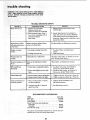
WARNING:
FOR:YOUR::OWN SAFETY, :TURN SWITCH
',OFF.: AND _REMOVE:: PLUG FROM POWER SOURCE
OUTLET BEFORE TROUBLE SHOOTING YOUR JOIN_
TROUBLESHOOTING
,_
TROUBLE
Motor will not run.
CHART
,,,,,,,,,,
_
,
PROBABLE CAUSE,
1. Defective On-Off switch.
Defective switch cord.
Defective switch box receptacle.
2, Motor protector open, (only if
your motor is equipped with an
.....
REMEDY
1. RePlace defective parts before using
machine again.
2. Consult Sears Service. Any attempt to
repair this motor may create a HAZARD
unlessrepair is done by a qualified service
technician. Repair service is available at your
nearest Sears Store.
overload protector).
Other cause
.i
i
p_.
_
i
J
i i
H
i i
,_J,
Wood strikes outfeed
table after passingover
cutter head;
Bladesimproperly adjusted below
surface of outfeed table.
......
Re-adjust blades, see Maintenance section.
Ripples on planed
surface.
1. one blade set higher than other.
I. Re-adjust blades, see Maintenance
section.
2. Feed wood slower.
2. Feeding wood too fast.
Planed surface not
straight.
=l
Infeed table out of adjustment.
,.
Excessive gouging at end
of Cut,
90 ° and 45° cuts
inaccurate,
LL
Re-adjust infeed table, see Getting To Know
your Jointer Planer section.
JL
:
Bladesset too high above outfeed
Reset blades, see Maintenance
table.
::
i _ 1, Fence stops not adjusted properly.
_
" : ........
2. Fence slide bracket not even with
table.
:
_
=
I
section.
....
1. Re-adjust fence stops, see Getting To
Know your Jointer Planer section.
2, Re-adjust slide bracket, see Getting To
Know your Jointer Planer section.
'L =H
I
Infeed table loose.
1. Dovetail spacer requires adjustment,
Cutter guard does no;€ i t. Return spring broken, or spring
function proper_y,
•
has been weakened.
2. Improper assembly of spring or
guard rnounting.
RECOMMENDED
1. Tighten
screw, key 10, see fig. 2, Parts List.
screws, key 18, see fig. 2, Parts List.
t.
spring
Replace
Maintenance
immediately.
section.
2. See Maintenance
ACCESSOR I ES
ITEM
Steel Legs ...............................
Floor Stand .............................
Cutter Blades ..............................
Power Tool K now-how Handbooks
Radial Saw ..............................
Table Saw ..............................
Knife Setting Gauge ........................
CAT. NO.
9-22245
9-22216
9-2293
9-2917
9-2918
9-2647
The above recommended accessoriesare current and were
-available at the time this manuat was printed.
26
section.
See
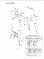
1
7
2
FIGURE
K .=y
N o.
Part
No.
1
2
3
4
5
6
7
8
9
10
67033
60314
STD55t225
STD541025
67032
62614
62204
67034
STD541250
803835
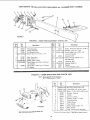
HARDWARE
1-
LEGS
PARTS
LIST
Description
Stiffener,
o *Screw,
End
Truss Hd.
o *Lockwasher,
• *Nut,
1/4 -
20 × 5/8
1/4 External
Hex 1/4 - 20
Stiffener,
Side
Leg
m Clip,
Cord
Support,
o'Nut,
•
Motor
Hex Hd. 1/2 - t3
Foot,
Leveling
FOR MOUNTING
TOOL AND MOTOR
FIGURE 1
STD532507
STD551231
STD55103!
$TD523120
STD541231
27
• *Bolt, Carriage 5/16t8 x 3/4
e*Lockwasher, 5/1 6 External
o'Washer, 1t/32 × 11/16 x 1/t6
• _Screw, Hex Hd, 5/16 - 18 x 2
O_Nut, Hex 5/16 -- !8
oSupptied
in Loose Parts Bag 67035
*Standard
Hardware
item
- May be Purchased
Locally.
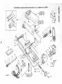
CRAFTSMAN
6-1!8 tNCH JOINTER-PLANER
MODEL
No, 113.20680
AND
113,206930
12
50
--49
SEE FIGURE 4 FOR
EXPLODED VIEW
........_3
11
1o
8
9
7
49
48
16
i0
oo
35
45
32
31
42
43
5
7
18
44
39
39
37
38
FIGURE 2
_r_SWITCH
. ./"
BOX ASSEMBLY
SEE FIGURE 5 FOR
EXPLODED VIEW
27
CRAFTSMAN 6-1/8 INCH JOINTER-PLANER
MODEL No. 113.20680 AND 113.206930
FIGURE 2 PARTS LIST
:•Key
No.
Part
No.
i
...........
i"8437
w ;hers ...........
21013
67020
21622
STD582062
1844t
3509
38879
60345
62023
Fence Assembly,
Knob,
£o
60255
37887
60O96
455872
(See Fig. 3)
STD541031
*Nut,
102832
Bearing
Ring,
67017
STD551025
*Washer,
Plain,
32
STD551125
*Washer,
Split
Lock,
1/4
33
STD55tt50
*Washer,
Split
Lock,
1/2
34
120238
*Nut,
35
21638
Rod, Sliding
36
18516
Stud,
37
STD551t31
Lockwasher,
38
STD523t17
Screw, Hex. Hd., 5/t6-18 x 1-3/4
39
STD551210
40
21733
Space r
Set Screw,
5/8"
Bore,
2" Dia. x 1/2 ';
Keyed
*Screw,
Set, 5/!6-18
*Screw,
He×. Hd. 1/4-20
x 5/16,
Soc Hd.
x 1/2
Pulley
Hex. 1/4-20
Sleeve
Hex.,
17/64
i.D.
1/2-13
Guard
Leveling
*Lockwasher,
Support
5/16
No.
- Guard
10 Int. Tooth
Pin
41
60078
42
STD580025
Key, Woodruff,
43
21636
Arbor
44
37158
45
67019
Ring, Retaining
Push Block/Hold
46
67021
Base
47
21237
Bracket,
Bracket-Support
48
132275
Screw,
t Motor, 1216
(Supplied With
49
21450
Head Assembly,
50
18112
1Blade,
Cutter
5t
60116
*Screw,
Cap. No. 10-32
52
21632
53
60117
'_Screw, Set, 5/16-24
54
60118
"Screw,
Belt, "V"
tPulley
1/2 x 52
with
Set Screw,
5/8"
Guard-Belt,
Bore,
2-t/2
Dia, x 1/2"
Keyed
Motor
"Screw, Ty 23 Pan 10_32 x t/2"
Support-Belt
Guard
Model
113.206930
:
Only)
CI_p "S'"
"Wrench
'Wrench
Screw
Hex.,
!/8
Hex., 5/32
Mach.,
1/4-20
x t-t/4
Truss Hd.
*Screw,
Mach.,
5/16-18
x 1/2",
3_!/4
Bowed 5/8
Down
Fence Slide
Mach.,
Wedge, Cutter
Shaft,
Elevating
67036
"Standard
tStock
most
Hardware
Item
-
May
item -- May Be Purchased
be secured
Sears or Simpsons-Sears
through
Retail
the
Stores
Owners
Locally.
Hardware
Department
or Catalog
Order
of
Houses.
Hex. Hd.
No. 9
Mach.,
1/4-20
x 1, Fil. Hd. Slotted
Compfete
Manual
Cutter
x 3/4
Soc. Hd.
8tade
x 7/8 Soc. Hd.
No. 10-32
Soc. Hd.
Knob,
Dog Pt.,
31
wiLockwasher
63410
67016
x 1 Full
Hd.
30
Retaining
Belt Guard,
5/16-18
Screw, Set, 5/16-18
5/8
Bal!
Bowed
Pulley with
Hex.,
............
_,
Guard
Retaining
V-Groove,
60252
STD601105
60253
60254
67031
28
29
Slotted
Washer, Sliding
Ring,
Description
, ,,,,,,,,l .....
Complete
* Ring, Retaining
*Nut,
No.
1-1/2
V-Groove,
STD503103
STD522505
67008
STD541025
STD304520
30646
Part
Key
No.
Description
(not itlus.)
x t/2,
Flat:
i
•
pair, parts
!CRAFTSMAN
6-1/8
iNCH
3OtINTER-PLANER
MODEL No. 113.20680
AND 113.206930
21
/
/
/
22
23
!
'\
\
\
2
\
FIGURE 3
5
FIGURE
No.
2
3
4
5
6
7
8
9
t0
11 :
12
TABLE
Part
Key
1
3 INFEED
Description
No.
STD 561210
67015
67014
STD511107
STD551210
STD551010
38779
67011
67012
STD522505
STD551025
: 121812
*Standard
Washer,
No.
10
Spring, Guard
Plate Support
Bushing
"Screw,
C_p,
1_/4-20
*Wastler,
Pt.ai:rto
Plate, Tension
Hardware
items--
MaY
x
112, He×. Hd.
1 7/.64
8.e
Purchased
Key
Part
No.
No.
i3
Pin, Cotter,
1/8. x 1
Guard
Table (with
Name
P_ate)
Screw Pan Hal.
10-32
x 7/8
Lockwasher
No10
Locatl*i.
3O
PARTS LIST
21422
14
t5
16
17
18
21219
21218
STD 551131
21635
STD523112
19
STD551031
20
21
22
23
21204
STD54t025
STD551 t 25
STD522510
Description
Spacer, Dovetail
Dovetail,
Male
Dovetail,
Female
*Washer, Split Lock,
Screw, Spl.
*Screw, Cap, 5/16-18
Hex. Hd.
5/16
x 1-1/4
Washer, 5/16
Linkage Assembly
"Nut, Hex., 1/4-20
"Washer, Split Lock, 1/4
*Screw, Cap, 1/4-20 x 1, Hex.
Hd,
CRAFTSMAN
1
2
3
4
6-118 INCH JOINTER-PLANER
5
6
MODEL No. 113.20680
AND
113.206930
7
10
11
12
FIGURE
4
FIGURE
4 -21013
FENCE ASSEMBLY
: ,
Key
Part
No.
No.
Description
1
2
3
21013
21440
21430
STD 522512
4
5
6
7
21232
21736
STD551010
STD510802
Pin Assembly,
Stop
*Screw, Hex Hdo0 1/4-20
Screw, Set,
Body,
21229
Fence
t0
STD551210
_Washer,
1!
STD5 ! t 102
"Screw,
67009
STD 533725
14
Bind
15
x 1/2",
Full
Dog
Pt. Slotted
FIGURE
Description
Mach.,
Hd..
5 - 67024 SWITCH
21738
Cutter
Retainer,
Spacer
17
62331
Knob
BOX ASM, PARTS
3/8-16
x 2-1/2
Head
Bolt
Washer
47624
10 & 11
No. t0_32 x I/4.
Carriage,
t6
Key No's.
Slotted
Guard,
"Bolt,
STD551037
lncl.
Lock, Ext. Tooth
Ft,o und
No. 8-32 x 1/4,
1/4-20
No.
12
13
Hd., Slotted
102817
No.
......... _
Pan
End
Mach.
Part
x 1-1/4,
Scale, Fence Tilt
*Washer, Plain, 13/64
*Screw,
,,,
Key
9
Fence Assem bty
Plunger Assembly
Plate, Fence
PARTS LiST
, ,,,,,
35/64
I.D.
Assembly,
Lock
LIST
;NOTE: Above assembEe_do not include Key
No. 10. Order separately
if needed.
1 2
Description
Part
No,
*Nut
12
11
\
\
Hex.
21 0
* Lockwasher,
STD60I
tO3
*Screw,
\
4
Bracket,
62376
Out
60267
Switch,
7
60271
SEE WIRING
DIAGRAM
,
ON PAGE 25
*Standard
_Washer,
Cord,
31
Locking
21/32
With
x 1 x 1/64
Plug
Strain
60256
Key,
60287
Screw,
60316
37818
63467
Box,
Switch
Cap,
Flag Terminal,
Hardware
Item
x 3/8 Pan Hd.
Housing
let
Relief,
5
No. 10 lnt. Tooth
Ty 23, t0-32
602 69
603t
F]JGURE
10-32 x 3/8 x 1/8
STD55!
Switch
Nylon,
6-32 x 1/4
insulated
-- May Be Purchased
Locally.
_
•
.....
:
.......::<
iii
! /:•••
•
:3
•
i.......
• : /v
•
Sears
6-1/8
SERVmCE
UNCH JOUNTER-PLANER
Now that you have purchased your jointer-planer,
should a need
ever exist for repair parts or service, simply contact any
Sears Service Center and most Sears, Roebuck and Co. stores.
Be sure to provide all pertinent facts when you catl or visit.
MODEL NO.
]!3.20680
JOINTER/PLANER
ON LY
113.206930
JOtNTER/PLAN ER WITH
LEGS AND MOTOR
HOW TO ORDER
REPAIR
Sold
Part No. 67036
PARTS
by SEARS,
The model number of your 6-1/8 inch joiflter-planer
found on a plate attached to your infeed table.
WHEN ORDERING
REPAIR
FOLLOWING
INFORMATION:
PARTS,
ALWAYS
will
GIVE
be
THE
PART NUMBER
PART DESCRIPTION
MODEL NUMBER
113.20680
113.206930
NAME OF ITEM
6ot/8 INCH JOINTER-PLANER
All parts listed may be
and most Sears stores,
Iocaity, your order wifl
Repair Parts Distribution
ordered from any Sears Service Center
tf the parts you need are not stocked
be electronically
transmitted to a Sears
Center for handling.
ROEBUCK
AND
CO.,
Form No. SP4401
Chicago,
tL. 60684
Printed
U.S.A.
in U.S.A.
12/78