1
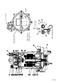
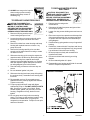
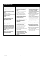
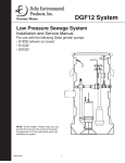
D1C20-21
2HP Centrifugal Grinder Pump
Installation & Service Manual
with Parts List
Grinder Pump for Residential and Pressure Sewer Applications
NOTE! To the installer: Please make sure you provide
this manual to the owner of the pumping equipment or
to the responsible party who maintains the system.
23833A594
1
2
23833A594
14D
26A
Insulated terminals
Non-insulated terminals
14E
14C
NOTE: On Item 26A
(clamp) once clamp is
tightened cut off excess
strap.
Motor Housing must be
positioned as shown
14F
14H
21A
Black screw on
motor end bell
1¼” NPT Discharge
Top View
PARTS LIST AND SAFETY CAUTIONS
Ref
No.
Part No.
1
2
3
4
5
5A
6
7
8
8
9
9A
10
11
12
13
14A
14B
14C
14D
14E
14F
14H
14I
16
16A
17
17A
18
19
20
20A
20B
20C
21
23
24
25
25A
26A
26433D002
21584B000
19099A012
21583B000
07597A018
14550A001
21582B000
05013A039
26434C010
26434C000
26430D001
05014A181
25327D000
19100A012
21576A010
08565A018
26466C101
26466C002
09859A827
09859A828
09859A829
09859A830
09859A832
24481A008
12141A015
20333A001
08565A013
12558A030
19331A005
05022A092
05030A235
05014A193
05030A234
25341A002
25338B001
11009A003K
21813B145
23838A010
20333A004
17190A004
CAUTION! NEVER WORK ON THE UNIT WITHOUT
DISCONNECTING THE ELECTRICAL POWER CORD.
Description
Case, volute
Flange, w/shredding ring
Screw, cap 1/4” x 1” long., SST (3 req’d)
Retainer, impeller, SST
Screw, flat head, 1/4” x 3/4” long
Sealant, Loctite grade 271
Impeller, grinding
Screw, set 1/4” x 3/8” long (2 req’d)
Impeller, pump plastic
Impeller, cast iron (optional)
Plate, seal/bearing
Gasket, tetraseal 7” x 6-3/4” x 1/8”
Housing, motor
Screw, cap, 5/16” x 1-1/4” long (8 req’d)
Seal, 7/8” shaft
Bearing, lower
Stator, w/shell, 2 hp, 230v, 1 ph
Rotor, w/shaft
Wire, w/term., black, 9” long
Wire, w/term., black 4-1/2” long
Wire, w/term., yellow, 4” long
Wire, w/term., red, 3” long
Wire, w/term., green, 6” long
Switch, mechanical
Capacitor, start with resistor
Clip, Capacitor
Bearing, upper
Ring, retaining
Washer, spring finger
Plug, pipe 1/4 NPT
Washer, SST, 3/32” thick
Gasket, rubber
Washer, SST, 1/32” thick
Nut, solid
Cord, power
Oil, transformer
Switch, float
Capacitor, run with resistor
Clip, capacitor
Clamp
POWER SUPPLY
The D1C20-21 Series grinder pump should only be
connected to a 230 volt, single phase, 60 Hz power
source. The pump will draw approximately 9.1 amperes
at minimum flow and 15.0 full load amperes. Locked
rotor current is 51.9 amperes. The pump must be
connected to a grounded power socket. DO NOT cut
off the ground pin from the power cord plug.
POWER CORD
A 20 foot power cord is attached to the grinder pump
via three insulated quick-disconnect terminals. To
replace a cord simply unscrew (turn counterclockwise)
cord nut from top of motor housing. Once cord nut is
completely loosened from housing, gently pull cord
upwards away from housing. While cord is being pulled,
it may be necessary to shift cord leads back and forth
to guide the insulated terminals through the hole in the
motor housing. Once the terminals have cleared the
hole, gently pull cord until terminals are completely
outside of motor housing. Then simply disconnect
terminals to remove cord.
To install new cord, reconnect terminals (black to black,
white to white, green to green), and guide terminals
back through hole in motor housing. Once terminals
have passed through the hole, retighten the cord nut
into housing. Tighten nut firmly but do not over tighten.
The power cord should be replaced if it has been
damaged in any way or the cord jacket has become
brittle with age.
MOTOR TYPE
USAGE
The D1C20-21 Series is a submersible wastewater
grinder pump designed specifically for individual
residential and pressure sewer applications. The pump
is to be used for domestic sewage only and not to be
used for pumping commercial or industrial sewage such
as motels, schools, apartments, factories, etc. THIS
PUMP IS NOT FOR USE IN HAZARDOUS LOCATIONS!
INSTRUCTIONS
These instructions cover only the grinder pump unit.
Separate instructions for the basin system are included
with the basin. Pump is not to be disassembled except
at a certified service station or at the factory. WARRANTY IS VOID IF PUMP IS TAKEN APART FOR
ANY REASON EXCEPT TO REPLACE GRINDER
IMPELLER, VOLUTE CASE/GRINDING RING.
INSPECTING PUMP
Before making any piping or electrical
connections, check the pump for shipping damage or cracks. Using a flat
screwdriver placed in the slot on the
shaft end, turn shaft and impellers to be
sure they are free. DO NOT TURN
IMPELLER WITH FINGERS AS EDGES
ARE SHARP.
23833A594
3
The D1C20-21 Series grinder pump contains a 3/4
frame, 2 HP, single phase, 60 Hz, 3450 R.P.M., capacitor start - capacitor run motor with Class F insulation
and built-in on-winding overload protection. Motor has
upper and lower ball bearings, and is oil-cooled and
lubricated. Resistance at motor leads is 1.8 ohms.
CAUTION: THE D1C20-21 SERIES GRINDER
PUMP SHOULD NEVER BE WORKED ON WITHOUT
FIRST DISCONNECTING THE POWER CORD.
OIL TYPE
The motor housing contains dielectric
transformer oil to provide good heat
transfer and lubrication of ball bearings, no other lubrication is required.
Oil level may be checked by removing
the nut (item 20C) and washers from
the top of the motor housing. The oil 3½
level should be 3-7/8” from the boss
(see figure 1) with pump setting
vertically. Do not over fill with oil.
Only dielectric transformer oil obtained
from an authorized service center
should be used.
Oil Level
PUMP SWITCH INSTALLATIONS
Ref
No.
24
Part No.
21813B145
Determining Pumping Range
In Inches (1 inch = 2.5 cm)
tether
3.5 6 10 14 18 22 24
length
Description
Switch, float
PUMP SWITCH INSTALLATION
INSTRUCTIONS
pumping
7 10 16 22 28 33 36
range
NOTE: In accordance to third party approval, pump
must be submerged a minimum of 8½” from bottom of
the legs on volute case during operation.
Use only as a guide. Pumping ranges are based on
testing in non-turbulent conditions. Range may vary
due to water temperature and cord shape. Note: As
the tether length increases, so does the variance of the
pumping range.
Mounting the Switch
Fig. B
1. Determine pumping range for installation (see
Figures A and B). Do not tether less than 3.5
inches (9 cm) from pipe.
2. Tighten strap around discharge pipe keeping
switch cable between strap and pipe to prevent
slippage (see Figure C).
3. Space small ties at least 1 inch (2.5 cm) apart (see
Figure C). To readjust ries, press small tie tabs
down.
4. To lock releasable tab, run remaining strap between tab and head. Tuck strap back through head
(see Figure C).
\
Fig. C
Direct Wire Install
1. Follow steps 1 through 4 of “Mounting The Switch”
2. Wire switch as shown below.
3. Check installation. Allow system to cycle to insure
proper operation.
Fig. A
Piggy-Back Plug Install
Electrical outlet must not be located in pump
chamber.
Electrical outlet voltage, piggyback plug voltage,
and pump voltage must match.
1. Follow steps 1 through 4 of “Mounting The Switch.”
2. Insert switch’s piggy-back plug into outlet.
3. Plug pump into piggy-back plug (see Figure A).
4. Check installation. Allow system to cycle to insure
proper operation.
4
23833A594
REPLACING PARTS
SAFETY WARNINGS
WARNING! Risk of electrical
shock. Pumps are supplied with a
grounding conductor and groundingtype attachment plug on the power
cord. To reduce the risk of electrical
shock, be certain that it is connected
Hazardous voltage can
only to properly grounded, groundingshock, burn or cause
death
type receptacle. DO NOT cut off
ground pin or use an adapter fitting.
DO NOT use an extension cord with this pump. Entire
plug may be cut off if a control panel is used. When
wiring this pump follow all local electrical, safety codes
and ordinances as well as most recent National Electric
Code (NEC-ANSI/NFPA).
The D1C20-21 Series grinder pumps have a GROUND
WIRE that is connected to a screw in the metal motor
housing. This wire goes to the receptacle or control box
which must be connected to a good outside GROUND
such as a metal water pipe or GROUND STAKE driven
at least 8 feet into the ground.
DISMANTLING PUMP FOR
REPLACEMENT PARTS
Before dismantling pump for replacement parts, clean
pump thoroughly. Knock off all scale and deposits.
Use sandblast if possible. Submerge complete unit in
Clorox solution for one hour before taking apart.
REPLACING GRINDER IMPELLER AND
GRINDER SHREDDING RING
This is the only disassembly operation allowed in the
field. All other repairs must be done at the factory or at
an authorized service station.
into tapped back-off holes in flange evenly tighten
screws to guide grinding ring out of pump volute
case.
3. Hold grinder impeller by prying
against impeller cutting bar and
remove cap screw from end of
shaft.
4. Use large screwdriver in slot in
end of shaft and bump on cutter
vane with plastic hammer. Bump
in counterclockwise direction as thread is right
hand. It may take several bumps to loosen
impeller.
If impeller cannot be loosened it will be necessary
to take unit to service station for service. DO NOT
CONTINUE TO POUND ON IMPELLER AS
IMPELLER AND SHAFT MAY BE DAMAGED.
5. If impeller comes off easily, clean up and replace if
worn.
6. Be sure pump impeller has not loosened when
grinder impeller is removed. This can be checked
on reassembly of grinder impeller and shredding
ring. Tips of impeller cutter vanes should extend
about 1/8” below bottom of shredding ring. If
distance is more, it means the pump impeller has
loosened, and if it is less, it means the shredding
ring is not properly seated.
If the pump impeller has loosened, remove grinder
impeller and shredding ring as described above
and remove bolts from volute case and remove
case. Plastic hammer can be used to bump on
casing discharge to loosen. Place gasket in oil to
prevent drying out. DO NOT loosen the pump
impeller further -- it is the seat for the seal spring.
STANDARD TOOLS REQUIRED:
1. Allen head socket set.
2. Standard socket wrench set.
3. Set of open end wrenches.
4. Plastic hammer.
5. Vise grip pliers.
6. Large screwdriver with heavy handle.
7. Three-cornered file.
7. After case is removed, wrap emery paper around
shaft and hold with vice grip pliers. Use cloth on
impeller and screw up against shoulder. Now
pump can be reassembled.
IMPORTANT: Pump should be thoroughly cleaned
of trash and deposits before starting disassembly
operations.
9. Use Never-Seeze or other graphite compound on
threads before replacing grinding impeller.
CAUTION! DISCONNECT ALL
POWER AND CONTROL WIRES TO
MOTOR AT CONTROL PANEL
BEFORE STARTING DISASSEMBLY
OPERATIONS. NEVER RELY ON
OPENING CIRCUIT BREAKER ONLY.
8. Clean all threads with wire brush and file, smooth
any threads that may have been nicked.
10. Be sure cap screw in bottom of shaft is tight. Hold
impeller with a screwdriver between cutter bar and
teeth of shredding ring while tightening cap screw.
11. Be sure impeller turns free by hand after reassembly. Some drag will occur due to the seal, but there
should be no binding or tight spots when turning
the grinder impeller.
Hazardous voltage can
shock, burn or cause
death
DISASSEMBLY OF SHREDDING RING
AND GRINDER IMPELLER
1. Remove three screws from grinder ring flange.
Grinder ring is pressed into flange for easy
removal.
2. Using allen head socket wrench thread two screws
23833A594
5
12. If impeller rubs or drags on shredding ring, loosen
bolts in shredding ring plate and tap with plastic
hammer to loosen, retighten screws. Be sure to
pull screw down evenly, applying pressure on all
three screws. DO NOT TIGHTEN ONE SCREW
CLEAR DOWN BEFORE ADJUSTING OTHER
SCREWS.
TO REPLACE MOTOR STATOR
AND SHELL
13. ALWAYS use a rag on the impeller
when turning to prevent cutting
hands on the sharp corners of
shredding ring.
CAUTION! DISCONNECT ALL
POWER AND CONTROL WIRES TO
MOTOR AT CONTROL PANEL
BEFORE STARTING DISASSEMBLY
OPERATIONS. NEVER RELY ON
OPENING CIRCUIT BREAKER ONLY.
TO REPLACE CAPACITORS ONLY
CAUTION! DISCONNECT ALL
POWER AND CONTROL WIRES TO
MOTOR AT CONTROL PANEL
BEFORE STARTING DISASSEMBLY
OPERATIONS. DO NOT RELY ON
OPENING CIRCUIT BREAKER ONLY.
1. Remove oil fill plug near the top of
motor housing and pour oil out.
1. Remove motor housing as described above.
Hazardous voltage can
shock, burn or cause
death
2. Disconnect all leads from power and ground wire
and set pump upright.
3. Loosen four long screws holding motor and remove
slowly.
Hazardous voltage can
shock, burn or cause
death
4. Either remove previous capacitors and clamps from
old motor and assemble onto new stator and shell
or replace with new capacitors and assemble per
wiring diagram.
2. Loosen the cord nut on power cord until cord is
loose enough to push cord down into motor
housing.
5. Position bearing spring washer on top of upper ball
bearing.
3. Remove four bolts from motor housing and bump
housing with a plastic hammer to loosen. Lay
pump on its side.
6. Position the “stator with shell” into place and line up
screws with bosses and tighten the (4) long screws.
Lay unit down in line with motor housing.
4. Remove the housing carefully to be sure that
enough cord is pushed into the housing to create
no tension on cord.
7. Be sure pump turns freely with screwdriver in
impeller end of shaft.
5. Slide motor housing up far enough to expose the
capacitors and to be able to lay the housing down.
8. Re-connect all terminals securely per wiring
diagram.
6. Disconnect wiring from capacitor and loosen
capacitor clamp and slide capacitor out. Replace
with new capacitor, tighten clamp and reconnect
per wiring diagram given in this manual.
9. Be sure tetraseal gasket is in place.
10. Reassemble motor housing and fill with oil as noted
above in “Capacitor Replacement”.
7. Check all wiring connectors to be sure they are
secure.
8. Be sure tetraseal gasket is in place.
WIRING DIAGRAM
9. Slide motor housing back onto pump while pulling
the cord out slowly. Assemble motor housing with
four bolts.
10. Re-assemble cord nut. Be sure washers are
seated and cord is pulled up against the washers.
Tighten nut securely.
11. Put pump upright and refill motor with Myers
submersible pump oil. DO NOT OVER FILL WITH
OIL. See figure 1 (page 3) for oil level. Reassemble washer, gasket, nut (item 20C) in motor
housing. Retighten nut firmly, but do not over
tighten.
12. Be sure pump turns freely before connecting
power. Turn pump on side and turn impeller, using
screwdriver in slotted shaft. Plug pump into
receptacle to test operation. Pump must run quiet
and free of vibration.
6
23833A594
TROUBLESHOOTING
SYMPTOMS
SOLUTIONS
Pump does not run or hum.
See A, B, C, D, E or F.
A. Line circuit breaker may be off; or
fuse if used, may be blown or
loose.
Pump runs but does not deliver
water.
See G, H, I, J, K or L.
B. Water level in sump may be too
low. Run in more water.
Pump runs and pumps out sump
but does not stop.
See M.
Pump runs but delivers only
small amount of water.
See I, J, K, L or N.
Fuse blows or circuit breaker
trips when pump starts.
See K, L, N, O or P.
Motor runs for short time then
stops. Then after short period
starts again. Indicates tripping
overload caused by symptom
shown.
See K, L, N or P.
For any other symptoms call
Myers Service Dealer.
23833A594
C. Pump cord plug may not be
making contact in receptacle..
D. If pump is using the series cord
plug, the two plugs may not be
plugged tight together.
E. Float may be stuck. Be sure float
operates freely in basin. Check
tether length of switch per
instructions.
F. If all symptoms check OK, motor
winding may be open; take to
service center for check.
G.Check valve may be installed
backwards. Arrow on valve
points in direction of flow.
H. Discharge shut-off valve, if used,
may be closed.
I. Pump may be air locked. Start
and stop several times by plugging and unplugging cord. Check
vent hole on pump case for
plugging.
7
J. Pump head may be too high.
Pump cannot deliver water over
100 ft. vertical. Horizontal
distance does not affect pumping,
except loss due to friction.
K. Inlet holes in pump base may be
clogged. Remove pump and
clean out openings.
L. Impeller or volute openings may
be plugged or partially plugged.
Remove pump and clean per
maintenance instructions. Check
tether length of switch per
instructions.
M.Float is stuck in up position. Be
sure float operates freely in basin.
N. Pump impeller may be partially
clogged causing motor to run
slow, resulting in motor overload.
O. Fuse size or circuit breaker is too
small. Must be 20 amps.
P. Defective motor stator. Return to
Myers service center.
LIMITED WARRANTY
Delta Environmental Products warrants to the original purchaser of each Delta Environmental Product grinder pump
system(s) that any part thereof which proves to be defective in material or workmanship within two year from date
of installation or 27 months from manufacture date, (extended warranty available) whichever comes first, will be
replaced at no charge with a new or remanufactured part, F.O.B. factory. Purchaser shall assume all responsibility
and expense from removal, reinstallation, and freight. Any item(s) designated as manufactured by others shall be
covered only by the express warranty of the manufacturer thereof. This warranty does not apply to damage
resulting from accident, alteration, design, misuse or abuse. The pump must be installed, operated, and maintained
in accordance with the published instructions of the appropriate Installation & Service Manual.
All dual seal grinders must have seal failure and heat sensors attached and functional for Warranty to be in effect.
If a seal failure should occur, Delta Environmental Products will cover only the lower seal and labor thereof. Labor
based on Authorized Service Center contract allowance. If the heat sensor is not attached and functional, Warranty
is void. If the seal failure sensor is not attached and functional, Warranty is void. If the material furnished to the
Buyer shall fail to conform to this contract or to any of the terms of this written warranty, Delta Environmental
Products shall replace such nonconforming material at the original point of delivery and shall furnish instruction for
its disposition. Any transportation charges involved in such disposition shall be for the Buyer’s account. The
Buyer’s exclusive and sole remedy on account or in respect of the furnishing of material that does not conform to
this contract or to this written warranty, shall be to secure replacement thereof as aforesaid. Delta Environmental
Products shall not in any event be liable for the cost of any labor expended on any such material or for any
incidental or consequential damages to anyone by reason of the fact that such material does not conform to this
contract or to this written warranty.
ALL IMPLIED WARRANTIES, INCLUDING THE IMPLIED WARRANTY OF MERCHANTABILITY AND THE
IMPLIED WARRANTY OF FITNESS FOR A PARTICULAR PURPOSE, ARE DISCLAIMED TO THE SAME
EXTENT AS THE EXPRESS WARRANTY CONTAINED HEREIN. Some states do not allow limitations on how
long an implied warranty lasts, so the above limitation may not apply to you. MANUFACTURER EXPRESSLY
DISCLAIMS AND EXCLUDES ANY LIABILITY FOR CONSEQUENTIAL OR INCIDENTAL DAMAGES FOR
BREACH OF ANY EXPRESS OR IMPLIED WARRANTY ARISING IN CONNECTION WITH THIS PRODUCT,
INCLUDING WITHOUT LIMITATION, WHETHER IN TORT, NEGLIGENCE, STRICT LIABILITY CONTRACT OR
OTHERWISE. Some States do not allow the exclusion or limitation of incidental or consequential damages, so the
above limitation or exclusion may not apply to you. This warranty gives you specific legal rights, and you may also
have other rights which vary from State to State.
8
23833A594
7/05