1
HP 91220/5 Disc Drives
Service Manual
Manual part number: 5957-6559
Prin ted: APRIL 1988
Printed in U. s. A.
Edition 2
E0488
rL:' HEWLETT
a!~ PACKARD
HEWLETT -PACKARD
P.O. Box 39, Boise, Idaho 83707-0039
Notice
The information contained in ':his document is subject to change without notice.
HEWLETT-PACKARD ~lA](ES NO WARRANTY OF ANY KIND WITH REGARD TO THIS
MATERIAL. I;SCLUDI~G. BliT NOT LI"lITED TO, THE IMPLIED "[ARRA!'iTIES OF
~IERCHANTABILITY A~D lFITNESS FOR A PARTICULAR PURPOSE. HEWLETT-PACKARD shall
not be liable for I!rrors contained herein or for incidental or consequential damages in connection with the
furnishing, performance: or use of this material.
HEWLETT-PACKARD assumes no responsibility for the use or reliability of its software on equipment
that is not furnished by HE'N'l.ETT-PACKARD.
This document contains proprietary information, which is protected by copyright. All rights are reserved.
N'J part of this document may be photocopied, reproduced or translated to another language without the
prior written consent of HEWLETT-PACKARD Company.
Copyright
b
@
1984, 1988 by HE\VLETT-PACKARD
Printing History
New editions are complete revisions of the manual. Update packages, which are issued between editions,
contain additional and replacement pages to be merged into the manual by the customer. The dates on
the title page change only when a new edition or a new update is published. No information is incorporated into a reprinting unless it appears as a prior update; the edition does not change when an update is
incorpora ted.
A software code may be printed before the date; this indicates the version level of. the software product at
the time the manual or update was issued. Many product updates and fixes do not, require manual changes and, conversely, manual corrections may be done without accompanyi~gproduct changes. Therefore,
do not expect a one-to-one correspondence between product upd'ates and manual updates.
Edition 1. ....................................................... JUNE 1984
Edition 2 ........................................................ APRIL 1988
c
Contents
Cha pter 1
Genera) Information
Introduction .................... '.' . . . . . . . . . . . . . . . . .. . . . . . . . . . . . . . . . . . . . . . . . . . . . . . . . . . . . . .. . . . . . . . . . . . . . . ..
Technical Specifications .......................................... '" . . . . . . . . . . . . . . . . . . ... . . . . . . . . . . . . . . . . ..
Power Requirements ..... : . . . . . . . . . . . . . . . . . . . . . . . . . . . . . . . . . . . . . . . . . . . . . . . . . . . . . . . . . . . . . . . . . . . . ... . . . . . . . . . ..
Environmental Specs ............. : " ...... , ...............................................................................
Equipment Supplied ........., . . . . . . . . . . . . . . . . . . . .. . . . . . . . . . . . . . . . . . . . . . . . . . . . . . . . . . . . . . . . . . . . . . . . . . . . . . . ...
Unpacking the HP 9122D/S Disc Drive ................................................................... , ........
Cleaning the Case. . . . . . . . . . . . . . . . . . . . . . . . . . . . . . . . . . . . . . . . . . . . . . . . . . . . . . . . . . . . . . . . . . . . . . . . . . . . . . . . . . . . . . ..
Chapter 2
Installation
Configuring Po'~er ......................................................................................................................
Setting The Line Voltage Select Switch ..............................................................................
Fuses ...................... " ............. "" ..................................................................... , ..........................
Power Cords............................................................................................................................ ,
Selecting the Device Address. . . . . . . . . . . . . . . . . . . . . . . . . . . . . . . . . . . . . . . . . . . . . . . . . . . . . . . . . . . . . . . . . . . . . . . . ....
Disc Compatibility .................................................................................................................
Con troIs and Indica tors. . . . . . . . . . . . . . . . . . . . . . . . . . . . . . . . . . . . . . . . . . . . . . . . . . . . . . . . . . . . . . . . . . . . . . . . . . . . . . . . ...
Media Moni tor ........... ,. . . . . . . . . . . . . . . . . . . . . . . . . . . . . . . . . . . . . . . . . . . . . . . . . . . . . . . . . . . . . . . . . . . . . . . . . . . . ...
Power-On Self test .............................................................................................................
Write Protect Error on Initialization ....................................................................
Chapter 3
Interface Information
Page
1- 1
1-1
1-1
1- 2
1- 2
1- 3
1- 3
1- 4
Page
2-1
2-1
2-1
2-1
2- 1
2- 2
2-3
2- 4
2- 5
2-5
2-5
Page
3-1
HP-IB Interface ...................................................................................................... 3-1
Instaiia tion. . . . . . . . . . . . . . . . . . . . . . . . . . . . . . . . . . . . . . . . . . . . . . . . . . . . . . . . . . . . . . . . . . . . . . . . . . . . . . . . . . . . . . . . . . .. 3- 1
HP-IB Interface Restrictions ............................................................ , ............. '" .......... 3-1
Chapter 4
Trou bleshooting
Repair Philosophy ....................................................................................................
Non -Exchange Assemblies .........................................................................................
Exchange Assemblies .........................................................................................
Controller Electronics and Power Supply Assembly ..........................................................
Page
4-1
4-1
4-1
4-1
4- 2
e
Contents (continued)
5elftest ......................... , ......................................................................... 4-4
Available Tests ........................................................................................ 4-4
Selecting a 5elftest . . . . . . . . . . . . . . . . . . . . . . . . . . . . . . . . . . . . . . . . . . . . . . . . . . . . . . . . . . . . . . . . . . . . . . . . . . . . . . . . . . .. 4 - 5
Troubleshooting Procedures .............................................................................. 4-6
Fault Isolation Procedures ............................. '" ........... _...... , .......... _... _...... _... 4-6
Troubleshooting Proc~~dures_ ... _. _.... _.. _. _.......................................................... 4-6
Troubleshooting Flowchart. '.' ........................................................................ 4-7
Using the 55/80 Exerciser .. ': ....................................................................... 4-11
DERRORS ........................................................................................... 4-11
Hints on Using the 55/80 Exerciser .................................................................. 4-12
Adjustments ................. '.' ................................ , ...... " .............. , ................. 4·-14
PLL Adjustment ..................................................................................... 4·-14
Chapter 5
Assembly Access
Page
5-1
Introduction ................... , . . . . .. . . . . . . . . . . . . . . . . . . . . . . . . . . . . . . . . . . . . . . . . . . . . . . . . . . . . . . . . . . . . . . . . . .. 5-1
9122D/5 Parts List ...................................................................................... 5-1
Chapter 6
Product History
Page
6-1
Introduction ................ " ............................. " ................................. , ...... " .. 6-1
5.ervice Note History. . . . . . . . . . . . . . . . . . . . . . . . . . . . ... . . . . . . . . . . . . . . . . . . . . . . . . . . . . . . . . . . . . . . . . . . . . . . . . . . . . . .. 6-1
f
iCHAPTER I
GENERAL INFORMA TION
I
1
I
Introduction
The HP 9122 disc drives are random access data storage devices. The HP 9122S contains a single 3
1/2-inch -double-sided drive and the HP 9122D contains two 3 I/2-inch double sided disc drives. The
storage capacity ranges from 630K bytes to 7 8SK bytes depending on the sector size beng used.
The HP 9122 dics drives have beeR designed using the SUBSET 80 command set. Refer to the Subset 80
Reference Manua~, PN 595.8-4129, for a complete description of this command set.
Technical Specifications
HP 9122S
Number of drives
Net Weight
Height
Depth
Width
3.6kg
76 mm
285 mm
325 mm
Interface
HP-IB
HP 9122D
1
(8.5 lbs)
(2.99 in.)
(1 1 . 2 in.)
(12.8 in.)
4.5
76
285
325
2
kg
mm
mm
mm
(10 lbs)
(2.99 in. )
( 11 .2 in. )
(12.8 in. )
HP Double-Density Format
Encoding
Rotational Speed
Bit Density @ 600 RPM
Track Density
Tracks per Surface
Surfaces used per disc
MFM
600 RPM
Track 79 (Inside track) 8717 BPI
135 tracks per inch
80
2
1- 1
GENERAL
I!'FOR~IATION
Double-sided
Capacity
Bytes/Sector
Sectors/Track
Tracks
Data Tr,acks ~\vailable
256
16
80
(----
512
9
80
154
Single-sided
1024
5
80
------>
256
16
70
66
Access Time
Track-to-Track Seek
15 ms/tri!:ck, plus 42 ms settling
Maximum Track-to-Track
See k (8 a t r a c k ~i )
1242 ms
Average Track-to-Track
447 ms
Maximum Rotational Latency
100 ms
Average Rotational Latency
50 ms
Spindle Motor on time
400 ms
Maximum Data Access Time
(Seek plus Latency
plus Motor on time)
1.742 s
Average Data Access Time
497 ms
NOTE
The HP 9122 disc drives spare four complete tracks and
reserve two tracks for system use with double sided
formats, and spare four tracks in single sided format.
Power Requirements
86-125 volts or 195-250 volts @ 67 watts RMS (94 voltamps)
50-60 Hertz
Fuse lA, 250 for 115V setting
.5A, 250 for 230V setting
Environmental Specs
Operating Limits
Temperature
HumiditY'
Altitude'
Non-operating Limits
(Storage and Transit)
Temperature
Altitude
1-2
10 to 40°C (50 to 104°F)
20 to 80r. with maximum wet bulb
temperature (non-condensing) not
toe xc e e d 29 ° C (85 0 F) .
o to 4572 m (0 to 15,000 tt)
-40 to 60°C (-40 to 140°F)
-304 to 15240 m (-1000 to 50,000 tt)
GE~ERAL I~FOR~fATION
NOTE
The flexible disc in the HP 9122 disc drives is designed for
operation in a typical office environment. Use of the
equipment in an environment containing dirt, dust, or corrosive substances will cause the flexible disc drives and
medium life to be drastically reduced.
Equipment Supplied
The following equipment is supplied with each HP 9122 disc drive.
HP Part Number
Quantity
Description
Dependent on location
09122-90020
N/A
1150-1786
AC Power Cord
Operator's Manual
Disc
Shipping Disc
A package of ten discs, product number 92192A, is available from DMK.
Unpacking The HP 91 220/S Disc Drive
The disc drive was carefully inspected before shipment. Remove the unit from the shipping carton and
carefully inspect the unit for any physical damage that may have occurred during shipment. If you find
any damage, you should immediately notify the dealer and file a claim with any carriers involved.
[CAUTION
I
The disc drive is a precision instrument. Mechanical shock can
misalign the read/write head, resulting in read errors and/or
damaged discs whether the disc is operating or not.
When moving the disc unit, care must be taken to prevent ex-:
cessive shock. Install the shipping disc (P /N 1150-1786 for
half height drives and 1150-1787 for full height drives)
before moving it to another location. If you do not have the
parts metioned, they may be purchased from Hewlett Packard.'
1-3
GE",ERAL I\:FOR\1A TIO~
Cleaning the Case
The disc drive case is made from a white plastic material and is not painted. The rear panel has a durable,
non-toxic label. In the event of damage to the case finish, consult your HP Sales Office for touchup paints.
I CAUTION I
Chemical spray-·on cleaners used for appbances and other
household and industrial applications may damage the case
finish. Do not use detergents that contain ammonia, benzenes,.
chlorides, or abrasives.
Before cleaning the case, disconnect the power cord and HP-IB cables. Make sure that any disc is removed
from the drives. Dampen a clean, soft, lint -free cloth in a solution of clean water and mild soap. \Vipe the
soiled areas of the case, making sure that no cleaning solution gets inside the case. For cleaning more hea vily soiled areas, a solution of 80% clean water and 20% isopropyl alcohol may be used. Dry the areas that had
cleaning solution applied with a.nother clean, soft, lint-free cloth. A non-abrasive eraser may be used to
remove pen and pencil marks.
1-4
ICHAPTER I
Installa tion
121
Configuring Power
Setting The Line Voltage Select Switch
The voltage select switch on the rear panel must be set to the nominal line voltage for the area in _which it
is operating. Figure 2-1 shows the setting for the voltage select switch for the various voltages.
[g]@
OR
11SV
Figure 2-1. Line Voltage Select Switch
Fuses
The part numbers of the fuses used for the two voltage ranges of 90-125 and 180-250 VAC are
2110-0001 and 2110-0012 respectively.
'~.A~f(~~~5
.
..
-'
Always disconnect the disc drive from any AC line before
changing fuses.
Power Cords
The power cord supplied by HP has polarities matched to the power sockets on the equipment. See Figure
2- 2 for details on the power cords.
2-1
InstallathJn
lUI.. and <:SA!1fJPf'OY9d for U84t in the United States ot Am&rica and Canada Wh equipment set
tor either 100 :')t 120 Vac ~Ition.
2Ul and CSA ar-proved for USE' in the Ur4ted States of America and Canada with equipment set
tor eithit' 2GO or 240 Vac, ooenltion.
Figu.re 2 - 2. A vaila bIe Power Cords.
Selecting the
Devic~! Addn~ss
Each device in an HP-IB system must be set to a unique device address. The HP 91220/5 contains address
switches located on the rear panel for programming in this address. 5ee the mass storage information of
your controller for aJdressing inf'Jrma tiCin concerning mass storage devices. See Figure 2 - 5 for switch locations. An HP-IB address of 0 is set at the factory before shipment.
Prior to setting the device address switches, turn the disc drive AC line switch OFF. This is because part of
the seIftest and power-up sequen,;e includes a check to see what the address switch settings are. Each time
power is applied to the disc drive these switch settings are checked, so if you change the switches be sure to
cycle the power switch.
The switches can be set to anyone of eight addresses, from 0 through 7. Refer to Figure 2- 3 when setting
these switches to the desired device address.
2-2
Installa tion
Position of 4 small switches
-
Address
Left
Left
Middle
Right
Right
0
1
2
3
4
Down
Down
Down
Down
Down
Down
Down
Down
Down
Down
Down
Down
Up
Up
Up
Up
Down
Down
Up
Up
Down
Down
Up
Up
Down
Up
Down
Up
Down
Up
Down
Up
Middle
5
6
7
Figure 2-3. Device Address Switch Settings
Disc Compatibility
The table in Figure 2 -4 details the recommended usage of single-sided and double discs. Words used in the
table are defined as follows:
* "Exchange only" means that the disc should be used only for exchanging
data and programs with single-sided disc drives, and should not be used
on a daily basis.
* "OK
II
means that the disc may be used on a daily basis.
Single-sided HP disc
exchange only
Double-sided HP media in
single-sided format
OK
Double-sided HP media in
double-sided format
OK
HP software
OK
Figure 2-4. Usage of Single- and Double-sided Flexible Discs.
2-3
Insta lla t ion
Controls and Indicators
-..a-.rTT
--1CeI -
9122
AC Power SWit-Ch--7
Disc Access Light
Disc Eje t Button
Disc Eje t Button
for Drive 0
for Drive 1
for Drive 0
SelHest Indicate,r
(Viewed through Air
Seriol number prefix 2518A and below
I.
Irttake Slel~)
. I.
Disc Ac<::es3 Un, ht
':I
for Drive 1
== I!i
=
I
:====
9122
II
Il
--=E:=J=~
/
AC POW?SWitCh
7
t::ll
,/
i
If
/
/'
Disc Access Light
Lntake Slots)
/
/
Disc Eje< t Button
for Drive 0
for Drive 0
Selftest Indicato r"
(View·ed through Air
ISenol num~r p~fix 2614A and above
\
V
r=:ll
2
7
II
It
V
I
Disc Ejec t Butto n
for Drive 1
Disc Ac<::ess Ught
for Drive 1
AC INPUT
~~
o
L
o O[_,.:J O
10
~~ O~o
--1~~O@fl LU
~ ~ I[IJ]] 0
~-'+'----~-------------l~!-i
ADDRESS/
TEST SELECT
HP-IB
IALL serial number prefixes
Figure 2- 5. Controls and Indicators.
2-4
I
AC
SELECT SW
FUSE
Installa tion
~ledia ~lonitor
Through a feature called Tvfedia l\fonitor, the disc drive automatically monitors the cumulative use of each
individual disc. When the usage of a disc is approaching a level at which there is a risk of loss of data
through normal disc wear, the disc access light on the front panel blinks and a clicking sound is heard.
Commands will still be performed by the computer. However, after a command has been performed, the disc
drive immediately resumes the warning indication.
When the Media Monitor warning occurs, immediately copy your disc. If you continue to use this disc, the
disc drive will eventually automatically write protect the disc. After that time, you will only be able to
read data from the disc or copy the disc.
Power-on Self test
A power-on selftest is performed automatically when you turn on the disc drive. The selftest first checks
the HP-IB, FDC, RAM, and ROM, followed by a WRITE/READ test (if an initialized, non write-protected
disc is inserted). When a WRITE test is 'performed, it is done on a reserved area of the disc and no user data
is at risk. The Selftest LED acts as a pass/fail indicator and is visible through the air intake slots.
When an initialized, unprotected disc is inserted; read, write, and motor-speed tests are performed. A writeprotected disc will not allow the read and write tests to run. If the disc access light stays on after the normal testing time, an error within the disc drive has been detected. If an error occurs, refer to Chapter 4 for
troubleshooting procedures.
Write Protect Error on Initialization
A motor speed check is performed before initialization is performed. If the motor speed is on either side of
the tolerance allowed, a Write Protect Error is generated and the disc cannot be initialized. At this point,
insert another disc. If a write protect error is generated again, refer to Chapter 4 for troubleshooting
procedures. If no write protect error occurs with the second disc, then the first disc used is bad and should
be discarded.
2-5
ICHAPTER I
Interface Information
I 3
I
HP -18 Interface
Installation
The HP 91220/5 is connected to the computer via the Hewlett-Packard Interface Bus (HP-IB). Refer to
Figure 3-1 for a list of the HP-IB interface c~bles used with HP computers.
Length
Accessory Number
1 metre
10833 A
2 metres
10833B
4 metres
10833C
0.5 metres
10833D
Figure 3-1. HP-IB Interface Cables
All the cables listed above are completely shielded to eliminate Radio Frequency Interference (RFI). The use
of unshielded cables will cause increased RFI in the area of operation.
I CAUTION I
Never turn the disc drive off or remove the disc from the
drive when the disc access light is on; doing so can cause loss of
data.
HP-IB Interface Restrictions
1. All the AC line switches (of the host system) must be turned "OFF" when connecting (and disconnecting)
devices to the system.
2. The total length of cable permitted in one bus system must be less than or equal to two metres times the
number of devices connected together (the interface card is considered one device).
3. The total length of the cable must not exceed 20 metres. For example, a system containing six devices
can be connected together with cables that have a total length less than or equal to 12 metres (six
devices x 2m/device = 12 metres). The individual lengths of cable may be distributed in any manner
desired as long as the total length does not exceed the allowed maximum. If more than 10 devices are to
3-1
Interface Information
be connected together, cables shorter than two metres must be used between some of the devices to keep
the total cable length less than 20 metres.
4. The max:imum number of devices that can be connected together in a one-bus system is 15.
There are no restrictions to the way cables may be connected together; however, it is recommended that no
more than four piggyback conneGtors be stacked together on one device. The resulting structure could exert
enough force on thf~ connector mounting to damage it.
3-2
ICHAPTERi
~T_r_o_ub_l_e_s_ho_o_t_in
__g____________~1
4
I
Repair Philosophy
The HP 9 12 20/S are serviced on the exchange program.
Non-Exchange Assemblies
Part Number
09123-61611
09121-61611
09121-68511
09121-61612
09122-68802
2110-0001
2110-0012
Description
- RIBBON CABLE ASSEMBLY
RIBBON CABLE ASSEMBLY
FAN ASSEMBLY
DC POWER CABLE
LINE FILTER ASSEMBLY
FUSE 1A 250 VOLT
FUSE 1/2A 250 'VOLT
SIN Prefix 2614A
SIN Prefix 2518A
and above
and below
X
X
X
X
X
X
X
X
X
X
X
Exchange Assemblies
09122-69511
09122-69514
09114-69511
09123-69101
Controller
Controller
3 1/2-inch
3 1/2-inch
PCA
PCA
X
disc drive
disc drive
X
X
X
4-1
TROUBlESHOOTLSG
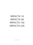
Controller Electronics and Power Supply Assembly
Figure 4-1 represents the powet supply and controller electronics (SIN Prefix 251 8A and below) of the
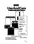
printed circuit assembly (peA). Figure 4- 2 represents the supply and controller electronics (SIN Prefix
2614-A, 2615A and above) of the peA.
The following information applies to both controller peAs shown in Figure 4-1 and 4- 2. Jumper J6 is used
to configure the controller peA for either a single disc drive or for two disc drives (9122S or 9122D respectively). J7 is used to start the service tests. Jumper J6 is shown in the 91220 position, and J7 is shown in
the normal operating position.
HP-18
L,__
SELECT CODE
1
-,D
f
J5
-J
L--'tt -ip--r
o ••••
".. ,-.........r---_ _ _
CJ CJ
JJ
J4
TP
09122-69501
SW1
TP7
50
o
0
TP8
TP9
o
o TP 10
0
TP6
Jt
TPt +5VOC
TP2 +12VOC
TPJ -IZVOC
J 1 TO FlEXIBLE OISC ORI\IES
J2 HP-IB
TP4 GNO
JJ,J4 ~R TO OISC ORIVES
TP5 INDEX
TP6 TRKO
J5 TO F"AN
TP7 READ DATA
TP8 WRITE DATA
J6 SINGLE OR DOUBLE
J7 SEFMCE TEST
TP9 eNO
TPl0 +5VOC
TP 1 1 Re;..o eLK
pu.)~
TP1
o
TP 2
Fuse F2 is fo" +5V and -11Y supplies
Fuse F3 is for the + 12V siupply and the Fan
R11
o
'------.., 0 TP
J
()
LED 1
-~
SELFrEST LED
Fi~~ure
4-2
4-1. Controller and Power Supply PCA(09122-6951l)
TROUBLESHOOTI~G
HP-IB
Fl
SW3 Select Code
J7
J5
To Fan
J6
o
1
00
00.
F3 --+--f-~---~"-!
J4
r---J-3-a-nd-J-4--'
TSt
~
P2
c
Index
Trk 0
C
Read Da ta
P1
Slimline drives
GNO
-+---;"""""'I"I"!---
~~ ~~ ~
i
Not used With
TP4
1000001
Fuse F2 is
Fuse F3 is
for +'5'1 and
-12'/ suppies
for +12V and
the fan
I~R.t.I- R11
TP1
Pll.. Adj
+5V
TP2
+12'1
-12'/
Self test LED
Figure 4-2. Controller and Power Supply PCA (09122-69504)
4-3
TROCBLESHOOTING
Self test
The self test diagn~)stic capability of the HP 91220/5 can be initiated in three ways: Power-on, Service initiated, and Host initiated. The HP 9122 power-on self test tests the RA'\f, ROM, FOe and the HP-IB chips,
and performs a set!k test. The HP 9122 also performs an index period test if any media is in the disc drive
and a \Vrite/Read test if format':ed non write-protected discs are installed in the drive prior to powering on
the unit.
Available Test
The following Service Test are available on the HP 91220/S products:
Test Number
Test Time
Test DescriPtion
RAM
1-2s
All patterns are written in all
locations of RAM
ROM
1-2s
A checksum calculation is performed
2
HP-IB chip
1 -2s
Two of the registers are written and
their content verified.
3
FOe chip
1 -2s
Two of the registers are written and
their content verified.
4
Drive 0 See,k
2-3s
Commands are given to the FOe to move
the head on and off of track o. The
track 0 indicator is checked to see that
movement occurred.
5
Drive
see,k
:2-3s
Same as above but on drive 1.
6
Motor 0 spe'ed
:2-35
The head is stepped to track 35 and
loaded. The period of the index pulse
is measured and compared against the
specification. No test if no media in
drive.
7
Motor 1 speed
:2-3s
Same as above but on drive 1.
Write on every sector ~f the disc and
verify the data written.
0
8
* Write/verify
disc 0
:2 min.
9
* Write/verify
disc 1
''}
10
* Verify
11
* Verify
12
4--4
min.
Same as above but on drive 1.
disc 0
min
All sectors in the data area of the disc
are checked for CRe errors.
disc
min.
Same as above but on drive 1.
min.
The disc is re-initialized with a 011
data pattern.
Format disc 0
,,"
TROCBLESHOOTING
13
Format disc
1 min.
Same as above but on drive 1.
14
PLL test
1-2s
The free running frequency of the PLL is
checked. The disc in drive 0 is used
for the test. and its format is destroyed
by the testing procedure.
NOTE: Format the disc again if you are going
to run test 8-11.
* Time
shown is for the format generated by test 12 or 13.
if the disc is initialized with another interleave factor.
This time will be different
NOTE
A disc must be in the drives to perform test 6 through 14. Ensure that the discs are not write protected and that they· are
initialized scratch discs.
Selecting a Selftest
The service diagnostic testing function allows selection and looping of any of the test choices in the following table.
To initiate a test, perform the following:
1. Apply power to the unit and allow the power-on selftest to complete.
2. Install formatted, unprotected discs if tests, 6 through 14 are to be performed. (Note: Scratch discs should
be used, as some tests destroy the data and format)
3. Set the HP-IB ADDRESS switch (SW3) to the desired test number (see figure 4- 3)
4. Short the TEST jumper pins 17, see figure 4-1 or 4- 2, with a jumper to start the test; LEAVE SHORTED
TO LOOP ON THE SELECTED TEST.
When a selftest is initiated, the HP 9122 leaves its normal peripheral mode and enters the diagnostic test
mode. The LED blinks (to show that the LED works).
The results of a successful test are displayed by the FAULT-LED blinking. A failure causes the LED to
stay on. Results are displayed for five seconds after a test is completed, followed by a complete power-up
sequence.
o
L
o
oCJo
TEST ~ (BI~
SELECiED
Figure 4- 3. Rear view of HP 9122 disc drive.
4-5
TROUBLESHOOTING
'Troubleshooting Procedures
This section is divided into Genl!ral information, a troubleshooting flowchart, procedures called out in the
flowchart, and inf 0rmation on i!.terpreting error codes obtained as well as use of the 55/30 Exerciser.
Fault Isolation Procedures
The following procedures will hdp to quickly and accurately
defective if a failure occurs.
det~rmine
which field replaceable assembly is
General Information
• If a flexible disc is damaged b:r a drive, inspect the HP 9122 to determine which drive is causing damage.
The drive heads are visi ble through the media slot. Replace any drive mechanism which is determined to
be damaging the media.
• If the fan is not operating check that the HP 9122 is receiving primary power that the voltage select
switch is set correctly, and that the primary fuse is good. Also check that the fan is plugged into the controller peA correctly, and that the power supply voltages on the controller PCA are correct.
(3
If possible, determine whether the customer has been using HP double-sided media. If the customer is
using media from other sources, or HP single-sided media in double-sided mode, it is possible that media
could be the caUSie of the problem.
Some media related problems which have occurred include visible wear of the disc, and a high pitched sound
from the drive while the disc is '~eing accessed. These problems have occurred when single-sided HP media
is being used heavily with the HP 9122 (instead of its intended use;to exchange data with single sided disc
drives) and with media from other vendors. Note that the head resonance problem may be found occasionally as an independen.t failure mode also.
Additional media related problems may occur as failure to initialize media, and intermittent failures.. In
some cases, media may cause an accumulation of residue on the read/write head of the disc drive which
must be removed, if possible, before the drive will work properly with HP media. Heads may be cleaned
using the 09122-89415 cleaning disc and the HD_CLN routine in the 5S/80 Exerciser SERVC module to
exercise the disc drive during the cleaning.
Power-on self test
The power-on self test tests the RAM, ROM, FDC, HP-IB chips, and performs a seek test (checks the track 0
detector) on each drive if no rnecj~ia is installed in the 9122. In addition, if media is installed in the drives, a
motor speed test is perfonned (checks the time between index pulses). If the media is formatted in a doublesided format and not write protected a write/read test is also performed on the system cylinder, which does
not affect any user data. (The write/read test is not performed if the disc is in singlesided format.)
Troubleshooting Procedures
• All tests specified in the following procedures should be performed using HP double-sided media ONLY.
• If an HP-85 and the SS/80 Exerciser, PIN 5010-0310, are available it is recommended that the Exerciser
be used to diagnose the failure and verify a repair. See information on use of the SS/80 Exerciser on page
4-11.
4-6
TROUBLESHOOTING
• Internal service diagnostics in the 9122 are referenced by "Test #" in the following procedures. Refer to
pages 4-4 and 4-5 for information on the tests and how to perform the tests.
SYSTEM TROUBLESHOOTING
POWER--QN
SELFTEST
WIO MEDIA
NO
TROUBLESHOOT
PER PO
POWER--QN
SELFTEST
W/MEDIA
TROUBLESHOOT
PERP1
TROUBLESHOOT
PER P2
CORRECT
SYSTEM
CONFIG
YES
TROUBLESHOOT
PER P3
NO
TROUBLESHOOT
PER P4
4-7
TROliBLESHOOTISG
The following procedures should be referenced when referred to by the "Troubleshooting Flow Chart".
PROCEDLRE PO (Sclftest indicator not on at power-on)
1. Check primary fuse
1. Check setting of the primary voltage select switch (115/220V) see Figure 2-l.
3. Check power supply voltages on the controller/power PCA. (See Figure 4-1, 4- 2). Repair by
replacing fuse~s F2 (-12V and + 5V) or F 3 (+ 12V) on controller PCA or replacing controller PCA.
PROCEDURE PI (Fails power on self test with out media in drive)
1. Check that alll internal cables in the drives are connected properly and are seated correctly.
2. Perform Tests 4 and 5 (seek or track 0 test) or perform TRK_ 0 test in the 55/80 Exerciser
5ER VC module.
91220
If one drive fails then replace the failing drive mechanism.
If both drives fail replace the controller/power PCA.
91225
If any of Tests 0- 3 fail then replace controller/power PCA.
If Tests ()- 3 pass, replace the drive mechanism.
PROCEDURE P2 (Fails power-on self test with media installed)
1. Perform Tests 6 and 7 (measures index period) or perform MTR_5PO test using the 55/80 Ex..erciser SERve module.
If disc access light comes on but drive fails then replace drive.
Ii disc lccess light does not come on then replace controller/power PCA.
PROCEDURE P3 (Consistent failure)
In some cases, media may cause this type of problem. Refer to statement concerning media in the "General"
information on page 4-6.
If the 55/80 Exerciser is available, do the following steps:
1. Perform the LOOPBAK test in the 55/80 Exerciser
I/O)
"~IANUAL"
module (This tests the 9122
If test fails then replace 9122 controller/power PCA
If test passes, go on to step two.
2. Perform the llNIT test in the 55/80 Exerciser "lVIANUAL" module on each unit. (This tests the
read/\vrite capability of the drive and the controller PCA.)
4--8
TROUBLESHOOTING
If one drive fails then replace the failing drive mechanism.
If both drives fail, then perform Test 14.
If test fails then adjust the PLL per procedure on page 4-14.
If PLL adjustment does not correct the problem or cannot be made, then replace the
controller/power PCA.
If INIT fails, it is possible that either the drive or controller/power peA cquld cause the
failure.
If disc access light comes on then perform Test 14
If Test fails then adjust the PLL per procedure on page 4-14
If the PLL adjustment does not correct the problem or cannot be made, then replace
the drive
If drive replacement does not correct the problem, then replace the original drive
the 91225 and change the controller/power PCA.
In
If disc access light did not come on, replace the controller first; if failure persists, replace
original controller and change the drive mechanism.
If 55/80 Exerciser is not available perform the following:
1. If a computer which supports the 9122 is available, attempt to INITIALIZE or FORMAT using
appropriate host commands on each drive. (This tests the read/write capability of the drive and
the controller/power PCA.)
If disc access light comes on,the HP 9122 I/O circuitry is good. If it does not come on,
replace the controller/power peA
If one drive fails then replace the failing drive mechanism
If both drives fail then perform Test 14.
If test fails then adjust the PLL per procedure on page 4-14
If PLL adjustment does not correct the problem or cannot be made, then replace the
controller/power peA.
If disc access light comes on the 9122 I/O circuitry is good
If disc access light does not come on then replace the controller/power peA
4-9
TROCBLESHOOTISG
If INITIALIZE/FOR\IAT fails, it is possible that either the drive or controller/power PCA
could cause the failure~.
If disc a,ccess light comes on then perform Test 14.
If test fails then adjust the PLL per procedure on page 4-14
IF PLL adjustment does not correct problem or cannot be made, then replace the drive.
If failure persists, replace original drive in the 91225 and change the controller/power
PCA.
If disc a,ccess li:sht did not come on, replace the power/controller PCA first; if failure persists, replace anginal controller and change the drive mechanism.
2. If no host computer is available: (This could occur if a drive -has failed and it is not possible to
boot the computer.)
91220
---Perform Tests 1.2 and 13
If vne drive fails then replace the failing drive mechanism.
If both drives fail, then perform test 14.
If Te:st 14 fails then adjust the PLL per procedure on page 4-14.
If PLL adjustment does not correct the problem or cannot be made, then replace the
controller/power PCA.
Pe rf orm Test 1 4
If test fa.ils then adjust the PLL per procedure on page 4-14.
If PLL adjustment does not correct the problem or cannot be made, then replace the
controller/power PCA.
If Test 14 passes then perform Test 12.
If Test 12 fails, then replace the drive; if failure persists, then replace orginal drive and
repla.ce power/controller PCA in 91225.
If Test 12 passes, replace power/controller peA; if failure persists, then replace original
powe:r/controller PCA and replace drive.
PROCEDURE P4 (Occasional or Intermittent failures)
Some causes of this type of problem include the following:
• Media problems; see information in "General" section.
4-10
TROUBLESHOOTING
• Environmental problems
Temperature/humidity outside the range specified for product
Dusty or dirty environment
Noise on power lines (Transients or continual noise on lines from other equipment)
Strong electromagnetic fields in vicinity of the drive
• Compatibility problems
Drive can read discs it has written but cannot read discs written on other drives, such as software discs
or data recorded on other drives.
This type of failure can be identified as follows:
Format disc in each drive using any available host or Tests 12 and 13
Exchange the discs just formatted between drive 0 and I, then attempt to read the discs with a
host computer, or verify the discs. Tests 10 and II may be used for this purpose.
If discs cannot be read, then a compatibility problem exists. The defective drive cannot be identified in this way. An additional test which MAY indicate the possible defective drive involves attempting to READ a disc which contains prerecorded software. (Tests 10 and 11 may also be used
for this test.)
Attempt to READ a known good disc, such as one containing prerecorded software. (Test 10 may
be used for this purpose)
• Infrequent read or write errors
The recommended method of verifying this type of failure is to use the tests in the R/W _TEST module
of the SS/80 Exerciser. These tests tra.nsfer data and when an error occurs the status information will
provide an indication of the possible cause of the problem. Refer to page 4-11 for a description of using
the SS/80 Exerciser. These tests can be set up to loop and can run for long periods of time.
If the error occurs on only one drive in a 9122D, then the drive is the probable cause of the problem. If
errors occur on both drives, then the controller is the most probable cause of the failure.
In the case of the 91225 there is no means of determining whether the disc mechanism or the controller
PCA is the cause of the problem.
Using the SS/80 Exerciser
The following information will help in interpreting the results obtained with the 55/80 Exerciser, and will
also assist in effective use of the Exerciser.
DERRORS
DERRORS may be indicated following the execution of certain commands. The .DERROR is basically
run-time status of the 9122 and provides additional information concerning what the product is doing.
4-11
TROUBLESHOOTING
The DERROR alone nev,er indkates a failure; additional status information will be displayed if a problem
exists.
Some common DERRORS which occur with the 9122 are as follows:
DERROR
Description
BA
Occurs following power on self test if media which is formatted in single sided
format is in the drive. Indicates that no read/write test was performed
during the se lftest.
SB
Occurs following power on self test if media which is formatted in double
sided format is in the drive. Indicates that a read/write test was pt!rformed
durin,g the self test.
B9
Occurs fonowing execution of INIT MEDIA. The number of tracks spared on
both sides of the media is then printed.
DERROR's BO thru BF, CO, and FO thru F 4- could occur. Except for the ones indicated above, these DERROR's do rlot provide significant additional information.
HINTS ON USING THE 5S/80 EXERCISER
The SS/80 Exercise:- provides some capabilities which are not available otherwise, and also provides more
formation about the 9122 than is otherwise available. Specifically, the' Exerciser provides the capability ~\}
transfer data and commands bt'::tween a host computer and the peripheral, and to performs certain tests
which cannot be implemented in any other way.
Please refer to the 5S/80 Exerci.ser manual, PIN 5958-4142 for an overview of the capabilities contained
in the Exerciser.
Some general
testin~
solutions which can be implemented using the Exerciser are as f\)llows:
HP-IB channel test
The LOOPBAK test in the MANUAL module tests the capability to
communicate with the product across the HP-IB.
Testing for R/W
errors
The R/W _TEST module allows either a Read Only, or a Write then
Read test to be performed on a single unit. This test (;an be set to loop
up to 32K times and allows extensive testing to identify a problem or
verify a repair.
General product
evaluation
The R/W __ TEST module provides capability to perform general
product testing and is recommended for this use.
Flexible dISC
tests
The SER VC module contains special flexible disc drive
speed, Track 0, Head cleaning routine, etc.
Complete product
evaluation
The OPER program provides the capability to test all units and volumes
of a disc drive without manually selecting each one. An OPER program
can be defined which will select each unit and volume and then perform a locate and verify, locate and read, locate an<i write, etc. The
program will allow looping to perform extensive testing.
4-12
tests-~{otor
TROUBLESHOOTING
if the drives are removed or replaced, refer to figures 4-4 or 4- 5 for the proper setting of the drive select
switch.
o
o
0
a
0
o
0
o
a
a
o
o
0
o
0
o
0
o
0
o
o
a
0
o
0
o
a
o
0
o
elsc ORNE St:L£CT SWITCH
/
F"ACTORY SETTINGS
DRIVE 0- 2
DRIVE 1- J
Figure 4-4. Disc Drive Select Switch(091l4-69 511).
.................
................•
Figure 4- 5. Disc Drive Select Switch (09123-69101).
4-13
TROL'BLESHOOTI'G
Adjustments
PLL Adjustment
The Phase LockL.Jop (PLL) adjustment is performed 1S follows. The PLL adjustment should be performed
when the umt e:utnts read/verify errors or fails the PLL test (TEST I·n
Use figure 4-1 or -t- 2 for locating test points.
1. Power on the unit, and allow the power-on selt-test to finish,
2. After two minutes warm up, attach the frequency counter test leads to tht! veo test-point
(TP 1 1). The freque:lcy should be 500K Hz ± 5%. If adjustment is necessary, adjust the variable
resistor R 11 for a frequency of 500 KHz±.l%(+-1 KHz).
3. Verify disc operation.
4--14-
ICHAPTERi
Assembly Access
I 5
I
Introduction
The following is additional information- which pertains to the 912 20/S and the 9121 D/S disc drives.
Top Cover Removal
To remove the top cover perform the following steps. Remove the AC 'power cord, then remove the two
cover securing screws on the rear of the unit. Depress the front panel power switch so that the cover will
clear the button. Tilt the rear of the cover upwards, and carefully remove the cover in a forward direction.
Assembly is performed in the reverse order, while depressing the power switch button through the front
panel hole.
NOTE
When installing drives (for units having a S/N prefix of
2614A and above), the controller PCA or the disc drive cable (
P/N 09123-61611) ensure that the disc drive cable is placed
between the drive and the controller PCA. Also, all star
washers removed during disassembly must be reinstailed.
These steps will ensure that the 91220/S will conform to all
the relevent FCC/VDE requirements for electromagnetic
emission.
91220/5 PARTS LIST
LEVEL
.2
.2
.2
.2
.2
.2
.2
.2
.2
.2
.2
.2
.2
.2
REFERENCE
DESIGNATOR
PART
NUMBER
DESCRIPTION
Al
09122-69511
CONTROLLER PCA
Cll ,12
C19
Cto
C17,22,23
TEMP .
C31-46
C4,5.8
C25,26
C9, 18,27 -30
C24
Ct ,20,21
C2.3. 15,16
C6
C7
0160-3622
0160-4574
0160-4805
0160-4830
0160-4831
0160-4832
0160-4835
0160-5098
0160-5349
0180-0210
0180-0291
0180-0692
0180-3007
0180-3260
C-F
C-F
C-F
C-F
C-F
C-F
C-F
C-F
C-F
C-F
C-F
C-F
C-F
C-F
.IUF 100V
1000PF 10%
47PF 5% 100V
2200PF 10%
4700PF 10%
.01UF 10%
.1UF lOX 50V
.22UF lOX
200PF 5';
3.3UF 15V
1UF 35V 10';
220UF 35V AL
.015F 25V AL
6800UF 50V
5-1
Assembly Access
LEVEL
REFERENCE
DESIGNATOR
PART
NUMBER
DESCRIPTION
.2
.2
.2
.2
.2
.2
.2
.2
.2
.2
.2
.2
.2
.2
.2
.2
.2
C13.14
0180-3390
0340-0122
0340-0583
0360-0124
0360-2035
0590-0305
068~I-l 0 15
C-F 33MF 100V
INSUL-FLG-BSHG
INSUL-XSTR TO-3
STUD-TERM
CONN-SGL CaNT
NUT-HEX 6-32
R-F 100 OHM .05
R-F lK 5~ .25\.1
.2
.2
.2
.2
.2
-,
.".2
.2
.2
.2
.2
.2
.2
.2
.2
.2
.2
.2
.2
.2
.2
.2
.2
.2
.2
.2
.2
.2
.2
5-2
BOTTOM
TEST PTS
J2
HEATSINK M.JT
Rl .39
R4.26.37.38
R40. 41,46
R30
R23.24
R32.33
R36
Rl
R25
R35
R5,27
R3
R9,22
R21 .45
R14,16,17,18
R15.19,
R28
R2.6,8
R12,13.20,29
R31,34,42,43
R44
T1
Tl
U40
ROM SOCKET
PLSTC GASKET
J1
J5
J3,J4
HP-IB-P2
J6.7.8
RPl,RP2.RP3
MOTOROLA
U41
U7,19.42
U16.27
U15.24,3:2
U10
068~r-l
025
0683-1045
lOOK .05
12 5~ .25\.1
120K .05
15K 5% .25W
5.6M .05
680 OHM.25W
820 OHM .05
464 OHM 1~
261 OHM .01
4.22K 1%
237 OHM '1 %
348 OHM 11lK 1% .125W
332 OHM 11562 OHM 1110.0K 1/8W
068:l-8215
069B-0082
0698-3132
0698-3154
0698-3442
0698-3445
o 75~' -0280
075?-0411
075?-0417
o 75 ~7 -0442
R-F
R-F
R-F
R-F
R-F
R-F
R-F
R-F
R-F
R-F
R- F
R-F
R-F
R-F
R-F
R-F
09121-00611
o91 :~ 1- 8250 0
09121-82501
09122-15511
1200-0861
120S-0500
120S-0503
125 'I -5153
1251-6429
125 'I -7018
1251-7651
1251-8248
1252-0058
12513-0141
1810-0204
181:3-0194
181B-1611
1820-0411
1820-1112
1820-1197
1820-1201
SHIELD-TRANS
TRANSFORMER
XFMR SUPPORT
IC-SONY DSCTL E.
SKT-Ie 28-CONT
HEATSINK
XSTR MOUNT T03
CN SGL-CONT TAB
CN3. 1 SQ POST
CN4.1 SQ POST
CN24 M AMP CHAMP
CN26.1 SQ POST
CN3. t SQ POST
JUMPER-REM
NTW'K-R 7XIK SIP
XTAL-CLK-OSC
IC-STATIC RAM
IC-SN7406N
IC SN74LS74AN
IC SN74LSOON
IC-SN74LS08N
068~1-1205
0683-1245
068:1-1535
0683-5655
068~r-6815
Assembly Access
LEVEL
RFERENCE
DESIGNATOR
PART
NUMBER
DESCRIPTION
.2
.2
.2
.2
.2
.2
.2
.2
.2
.2
.2
.2
.2
U2
U28
U31
U17,30
U20,23
U35
U36
U18,33
U25
U39
U21,U29
U22
U38
U37
U4.6
U1
U8
U14
U9
U11,12"
U3,5
U13
CR1,3
CR4
CR5-12
CR2
CRT4
CR13
LEDl
U26
RI0
F1
F1
F1
F2,3
XFMR MOUNT
1820-1202
1820-1216
1820-1300
1820-1416
1820-1433
1820-2024
1820-2046
1820-2096
1820-2549
1820-2624
1820-2684
1820-2686
1820-3006
1820-3318
1821-0001
1826-0210
1826-0346
1826-0412
1826-0555
1854-0611
1858-0058
1884-0074
1901-0050
1901-0518
1901-1135
1902-0029
1902-0040
1902-0074
1990-0450
1LH4-000 1
2100-0554
2110-0001
2110-0565
2110-0642
2110-0711
2200-0107
2200-0205
3101-0680
3101-2264
3101-2623
9100-0539
9140-0183
IC-74LSI0N
IC-SN74LSI38
IC SN74LS195N
IC SN74LS14N
IC SN74LS164N
IC-SN74LS244
IC SN74LS353N
IC SN74LS393N
IC-8291AP
IC-68B09
IC-74FOO N
IC-74F08 PC
IC-MB8876A CTLR
IC SN74ALS273N
XSTR-ARRAYCA3046
IC-LM361
IC-LM358
LM 393 V. COMPAR .
IC-L"1340LAZ-5
XSTR-2N6055 NPN
XSTR ARY MPQ3906
IC-2N5060
010 SWITCHING
010- SM-SIG-S
DIO-PWR 3A 70V
DIO-ZNR 12V 5~
DIO-ZNR T4V 5%
DIO-ZNR 7. 15V 5~
LED-LMP
TRANSCEIVER
R-V 500 OHM 10%
FUSE 1A 250V
CAP-FUSE HOLDER
FUHLR-EXTR POST
5 AMP FUSE
SCR-MACH 4-40
SCREW-MACHINE
SW-PB-DPDT
SW-RKR 4-1A
SWITCH-SLIDE
IDCTR 10UH 5~
IDCTR 20UH 10%
09122-68802
LINE FILTER ASSY
2110-0001
2110-0012
FUSE 1A 250V
FUSE .SA 250V
.2
.2
.2
.2
.2
.2
.2
.2
.2
.2
.2
.2
.2
.2
.2
.2
.2
.2
.2
.2
.2
.2
.2
.2
.2
.2
.2
.2
.2
SW1
SW3
SW2
L1
L2,L3,L4,L5
5-3
Assembly Access
LEVEL
.2
.2
.2
.2
.2
.2
.2
.2
.2
.2
.2
.2
.2
.2
.2
.2
.2
.2
.2
.2
.2
.2
.2
.2
.2
.2
.2
.2
.2
.2
.2
.2
.2
.2
.2
.2
.2
.2
.2
.2
.2
.2
.2
.2
.2
5-40
REFERENCE
DESIGNATOR
Cll .12
Cl9
CIO
C27
C17.22,23
C21.31-3:3,43-46
C4,5,8,39-42
C25.26
C9, 18 , 29 , 30
C24
Cl
C2, 3,15,16
C6
C7
C13,14
TP4
J2
RI ,39
R4,26,37,38,40
R41,49
R46.48
R30
R23,24
R32,33
R34
R7
R5
R3
R36
R9.22
R21,45
R14,16-1:3
R25,28
R27.35
R15,19
R2.6,8
R47
RIO, 12, 1.3 , 20 , 29
R31,42
T1
Tl
U40
PART
NUMBER
DESCRIPTION
09122-695]4
CONTROLLER PCA
0160-3622
0160-4574
0160-4805
0160-4810
0160-4830
0160-4832
0160-4835
016()-5098
016()-5349
0180-0210
018()-0291
Ol80-0692 "
Ol80-3007
0180-3260
0180-3390
0340-0122
0340-0583
0360-0124
0360-2035
0590-0305
068:3-1015
068:3-1025
C-F .1UF 100V
C-F 1000PF 10%
C-F 47PF 5% 100V
C-F 330PF 5%
C-F 2200PF 10~
C-F .0IUF 10%
C-F .IUF 1O~ 50V
C-F .22UF 10~
C-F 200PF 5"
C-F 3.3UF 15V
C-F lUF 35V 10~
C-F 220UF 35V AL
C-F .015F 25V AL
C-F 6800UF 50V
C-F 33UF 100V
INSUL-FLG-BSHG
INSUL-XSTR TO-3
STUD-TERM
CONN-SGL CONT
NUT HEX 6-32
R- FlO 0 OHM . 05
R-F 1K 5% .25\4
068:3-1035
068:3-1045
068:3-1205
068:3-1245
068:3-2735
068:3-5655
0698-0082
0698-3132
0698-3136
069B-3154
0698-3442
0698-3445
0698-3511
0690-4465
0757-0280
0757-0417
0757-0437
075J-0442
R-F
R-F
R-F
R-F
R-F
R-F
R-F
R-F
R-F
R-F
R-F
R-F
R-F
R-F
R- F
R-F
R-F
R-F
09121-00611
09121-48305
091 :~ 1-82500
091 :~ 1- 82501
09122-15514
TRANSISTOR SHIELD
STANO-OFF CAP
TRANSFORMER
XFMR SUPPORT
EPROM
10K .05 1/4W
lOOK .05
12 5~ .25W
120K .05
27K .05
5.6K .05
464 OHM 11261 OHM .01
17.8K 1%
4.22K 1%
237 OHM 1%
348 OHM 1%
665 .01
931 OHM 1%
1K 1% . 125W
562 OHM 114.75K 1%
10.OK 1/8W
Assembly Access
LEVEL
.2
.2
.2
.2
.2
.2
.2
.2
.2
.2
.2
.2
.2
.2
.2
.2
.2
.2
.2
.2
.2
.2
.2
.2
.2
.2
.2
.2
.2
.2
.2
.2
.2
.2
.2
.2
.2
.2
.2
.2
.2
.2
.2
.2
.2
.2
.2
.2
.2
REFERENCE
DESIGNATOR
J1
J5
P3
P2
J6.7.TS1
RPl.RP3
RP2
U41
U7.19.42
U16,27
U15,24.32
U10
U2
U28
U31
U17.30
U20.23
U35
U36
U18,33
U25
U39
U21 ,29
U22
U38
U37
U4,6
Ul
U8
U14
U9
Ul1,12
U3,5
U13
CR1,3
CR4
CR5-12
CR2
CR14
CR13
LED1
U26
R11
PART
NUMBER
DESCRIPTION
1200-0861
1205-0503
1205-0656
1251-5103
1251-5153
1251-6429
1251-7651
1251-8683
1252-0058
1258-0209
1810-0204
1810-0205
1813-0194
1818-1611
1820-0471
1820-1112
1820-1197
1820-1201
1820-1202
1820-1216
1820-1300
1820-1416
1820-1433
1820-2024
1820-2046
1820-2096 .
1820-2549
1820-2624
1820-2624
1820-2686
1820-3006
1820-3318
1821-0001
1826-0210
1826-0346
1826-0412
1826-0555
1854-0611
1858-0058
1884-0074
1901-0050
1901-0518
1901-1135
1902-0029
1902-0040
1902-0074
1990-0450
1Ui4-000 1
2100-0554
SKT-IC 28-CONT
XSTR MOUNT T03
HEAT SINK
CN5. 1 SO POST
CN SGL-CONT TAB
CN3. 1 SO POST
CN24 M AMP CHAMP
CONNECTOR.34 PIN
CN3. 1 SO POST
JUMPER-REMOVABLE
N1'\JK-R 7X1K SIP
NTWK-R 7X4.7KSIP
CRYSTAL OSC 8MHZ
IC STATIC RAM 2KIC SN7406N
IC SN74LS74AN
IC SN74LSOON
IC SN74LS08N
IC 74LS ION
IC SN74LS138
IC SN74LS195N
IC SN74LS14N
IC SN74LS164N
IC SN74LS244
IC SN74LS353N
Ie SN74LS393N
Ie 8291AP
Ie 68B09
Ie 74FOO N
Ie 74F08 PC
Ie MB8876A CTLR
Ie SN74ALS273N
XSTR-ARRAY (CA3046)
IC LM361
IC LM358
UM 393 VOLTAGE COMPAR
IC LM340LAZ-5
2N6055 NPN TRANSISTOR
MPQ3906 TRANSISTOR ARRAY
2N506 THYRISTOR
SWITCHING DIODE
SMALL SIGNAL DIODE
PO~ER DIODE (3A 70V)
ZENER DIODE (12V 5%)
ZENER DIODE (14V 5%)
ZENER DIODE (7. 15V 5%)
LED
IC (TRANSCEIVER)
VARIABLE RES (500 OHM 10%)
5-5
5-6
Assembly Access
Drive Mounting Hardware
(SIN prefix 2614A and above)
09122-24700
09122-24701
0515-1738
(SIN
~refix
0515-1738
STANDOFF
(5 ea)
STANDOFF
(1 ea)
MOUNTING SCREW (6 ea)
2518A and below)
MOUNTING SCREW-(6 ea)
Miscellaneous Parts
1
1-
1
1
1
1
1
1
FEET-REAR
LINE FILTER GNO
FRONT FEET
PCA Mounting
0403-0427
0515-1079
0624-0583
09121-00110
09121-48306
09121-48302
09121-48303
09121-61611-
BUMPER FOOT
SCREW
_SCREW
BASE
PUSH ROD,PLASTIC
PILLAR, SUPPORT
FOOT-MOLDED
RIBBON CABLE ASSEMBLY (SIN prefix 2518A
and below)
09123-61611
RIBBON CABLE ASSEMBLY (SIN prefix 2614A
and above)
09121-61612
DC POWER CABLE
09121-68511
5041-1203
2360-0117
FAN ASSEMBLY
PWR BUTTON, WHITE
6-32 SCREW
(SIN prefix 2518A and
below)
EXCHANGE ASSEMBLIES
091 14 -69511
FLEXIBLE DISC DRIVE
(SIN PREFIX 2518A AND BELOW)
09123-69101
FLEXIBLE DISC DRIVE
(SIN PREFIX 2614A AND ABOVE)
09122-69511
CONTROLLER PCA
(SIN PREFIX 2518A AND BELOW)
09122-69514
CONTROLLER PCA
(SIN PREFIX 2614A AND ABOVE)
5-7
Assembly Access
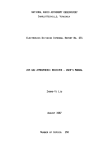
09114-69511
or
09123-69101
FLEXIBLE DISC DRIVES
----
D
I I --,
D
c
[
[]
~I
0 '- ~l
0
0
I
a
1
C)
J<4
J3
DO
a
CONTROLLER/POWER SUPPLY
09122-6951 '1
or
09122-69514
I
...J
OOQO.OOOOQO~~
-l~
I
~
~
FAN
09121 -68511
Location of Field Replaciable Assemblies (FRA)
5-8
&Jl'
L'~
0
0
C)
J
ICHAPTER I
~P_r_od_u_c_t_H_i_s_to_r_Y
_______________~1
6
I
Introduction
This section of the manual is complete for all 9122D/5 products now in the field. Applicable serial numbers are as follows:
HP 9122D/s - serial numbers prefixed by 2513A and below
- serial numbers prefixed by 2614a and above
Service Note History
The following table shows the service notes which have been issued against the HP 9122D/5 products.
service notes are provided at the end of this chapter for reference.
Service Note
Number
91220-1A
91220-2
91220-3
91220-4
91220-5
91220-6
91220-7
Description
SIN Prefix
Required screws in exchange drives
3 1/2-inch drive
New drive electronics
and
Cassette-up assembly
Potential Service Test failure
(Firmware update needed)
Controller/Power supply generates noise
Affects Read AMP. (New Controller PN 09122-69511)
New shipping disc
PN 1535-4881
Head damage on 09114-69511 drives. Rubber
wedge added for shipment (PN 9223-0648)
New drive and controller peA
The
Affected Part
ALL
09114-69510
09114-69511
ALL
09114-69511
2518A and
above
09122-69501
2513A and
below
Drive da te codes
2418 or 2432
09122-69501
09114-69511
Ali..
91220/S
ALL
09114-69511
09122-69504
91220-8
Torque specs for 09123-69101 drives
2614A
09123-69101
91220-9
New controller peA (PN 09122-69514)
2614A56267 to 70474
09122-69504
91220-10
New shipping disc
Futl height
=1150-1786
Half height
=1150-1787
ALL
91220/5
6-1
~J.~4U
-lA
SERVICE
NOT E
Supenedes:
UPUES TO:
AII\JftIaB
PP'ORM:
.AJltRAHTY:
91220
09114-69511
All Serial Numbers
Only \JnfU on
On''''''' 0
DTtNCEl)
A9~ 0
Al~c."o
lnforrNbon 0nIy~
~.,.,o
NORMAl
NOH!:
x
x
x
u. •• t
LMOft
,ARTS:
TRAVEl.:
Required Screws in Exchange Flexible
Aftum for wodIte 0
Aftum for -W9I 0
SERVIa
INVVITORY
See
~xt
0
WARRAHTY EXTENDED UNTlL:
SITUATION:
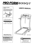
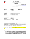
The 09114-69511 Flexible Disc drive is currently used in three
products; the 9114A, the 9122D/S. and the 91330. There are 5
possible locations for mounting-screws that attach the shield to
the frame of the drive. Each product requires a different minimum
number of screws. In some cases, screws must NOT be installed
in certain locations.
All drives in the 91220's have- been shipped with the proper
mounting-screws. However, many of the EXCHANGE drives shipped
prior to September 1984 contained only the one rear mounting-screw. The exchange drive is now being shipped with the
MAXIMUM number of screws to accommodate all products that use the
drive.
.
DESCRIPTION:
The 91220 requires the following:
Min. Required
Drive 0:
1,2,3,4,5
Drive 1:
1.2,3,4
Must Be Removed
5
If the required screws are not in the exchange drive, use screws
from the original (removed) drive.
Ul/tlIl
1320-4766 (1/83)
06 fl24/85-S800
rhdl
HEWLETT
~~ PACKARD
POW ~E. "'FORMATION. CALL YOUR LOCAL . . SALEI OR SERVICE OFFICE or £an C20tt 2I5-6OCQ . . . o..n (3121 255-8800. South (4041 ~11OO .We
1213) .70-7500 or (415) .ea·l2oo OR MUTE. Hewtm-hcbrd. 11'20 EtnOiiCilldero. hlo Alto, Califomil t4303. IN IUR~E. CALL YOUR LOCAL . . SALEI .,
IIRV~ OFFICI OR WRITE. H.wMn-hckardS.A...1.ru." loiHa.-Un.'.o. loz.CH.1211 Ur(rin 2·~.~. IN JAlM. Yo«oe-we~..sen~brd LICl..
1~.11. Y" Seglfftlwa City. ~ rmlCllon ...... 23.
e 1883 Hewlett-Packard Company
~inU.S..A
1012
3- I
I
1
2- 1
1-4
I
1
1
I
I
I
I
I
I
1-1
I
1
1
I
I
I
-I
I
Top View
I
I
I
I
1-5
I
I
I
1--------------------------------1
1--------------------------------1
S~ield
LM/tm
2012
.Mounting-Screw Locations
9122D-2
NOT E
C E
Supersedes:
APPLIES TO:
PERFORM:
91220 Dual Drive
WARRANTY:
-
09114-69511
3.5 Inch Drive Mechanism
(All Prefix 2518A and later)
All Units
x:
None
SUPERSE~ES
Only Unl:S en
A;~ee~e~'
At ?\1 Ncr'T'al Ca'·. ::
On Failure
Information 8"11(
=
EXTENDED
NORMAL
lS
NONE
X
LABOR:
PARTS:
TRAVEl..;
SERVICE
INVENTORY
::
Immealately C
X
X
3S IS ~
Return for update 0
Use
Return for salvage 0
~text
WARRANTY EXrENDEO UNTIL:
0
NA
Situation:
Starting with Serial Number prefix 2518A, a new 3.5 Inch Drive (PN09114-69511)
is being used in the 91220. The rrew drive has a different Drive Electronics
PCA (Fewer components) and Cassette-Up Assembly. The new drive will be used
interchangeably with the existing 3.5 Inch Drive, therefore it will be stocked
with the same exchange part number and no FSI action is required.
Cause: The drive is.being changed to reduce cost and improve reliability.
The new drive has fewer parts to increase reliability.
Warranty: Both drives will be used interchangeably using exchange part
number 09114-69511. No F.S.I or warranty action is required.
KK/tm
9320-4766 (1/83)
4/9/85 - 5800
rhO-
HEWLETT
~~ PACKA~D
FOR MORE INFORMATION. CALL YOUR LOCAL HP SALES OR SERVICE OFFICE or East {201) 2655000 • ·,1.r1wes' {312) 255·35:'D • S:. ... :~ .4041 95: '500 • Wes:
(213) 970·7500 or (415i 968·9200 OR WRITE. Hewleu·Packard, 1820 EmoarcadE"o. Palo Alto. C.Jltfornla 94383
IN EUROPE. C;'LL YOUR LOCAL HP SALES or
SERVICE OFFICE OR WRITE. Hewleu·Packard S.A .. 7. rue du 80Is-<lu·Lan, P.O. Box. CH·121 7 Mey"n 2· Geneva. SWIIZeriand. IN JAPAN. Yo,o~.lwa·""e""l .. r:·Pdc"dra l.r::: ..
'·27.15. Yabe Sag.amlhara City. KanagaVlla PrefK:ure. Japan 229.
<& , 983 Hewlett-Packard Company
Printed in U.S.A.
9122D-3
C E
S E R V
Supersedes:
PERFORM:
WARRANTY:
09122-69501 Firmware Change
Controller Power PCA
(All Prefix 2518A and later)
SUPERSEDES.
All Unlts~
Only Units on Agreerne", :::
Immealately Cl
At PM, Normal Call 0
APPLIES TO:
91220
Dual Drive
On FaIlure Cl
EXTENDED
Information Only Oi:
NORMAL
LABOR:
PARTS:
TRAVEL:
Potential Service Test Failure
NOT E
NONE
X
X
X
SERVICE
INVENTORY
Return tor update 0
Use as is :}C
Return tor salvage 0
See text 0
WARRANTY EXTENDED UNTIL;
NA
Symptom: The latest 3 1/2-inch Drive mechanism part number 09114-69511 date
codes 2513 and 2514, when in products with the older E-PROM, part number
09122-15512 and earlier, does not perform the jumper-initiated Format Test
correctly.
Due to timing differences between the new drive and controllers with older
firmware, step commands may riot all be performed by the drive during the
Service Format Test. When this occurs, all tracks will not be formatted. The
test will not indicate a failure as no read operation ;s done during the test.
A failure will not occu~ until an read or write operation is attempted. The
failure occurs on the jumoer-initiated Format Tests (Tests 12 and 13) ONLY.
No other tests or functions are effected.
Solution: The New E-PROM, part n~mber 09122-15513, corrects timing problems
for both the earlier and later drives. The Controller/Power PCA, part number
09122-69501 date code 2513 and later has the new E-PROM.
09114-69511
Drive Date Code
E-PROM PN
09122-15513 and later
E-PROM PN
09122-15512 and earlier
2418 and 2432
Will pass Service Format Test
on good unit
Will pass Service Format
Test on good unit
2513 and 2514
May not complete Service Format
Test.(All tracks may not be
forma tted)
Will pass Service Format
Test on good unit
Warranty: As no customer operations are affected, no warranty or F.S.r. action
is required. All other operations are unaffected.
KK/tm
5/9/85 - 5800
9320-4766 (1/83)
rhfll
HEWLETT
~~ PACKARD
FOR MORE INFORMATION, CALL YOUR LOCAL HP SALES OR SERVICE OFFICE or East (201) 265·5000 • MIr1",,~s· (312) 255·9800. South (4041 955·1500. West
(213) 970·7500 or (415) 968·9200 OR WRITE, Hewlen-Packard, 1820 Embarcadero, Palo Alta, California 94303.
SERVICE OFFICE OR WRITE, Hewien-Packard S.A., 7, rue d'J BOIS-du·Lan, P.O.
1·27.15, Yabe Sagam.hara City, Kanagawa Prefecture, JaPlin 229.
© 1983 Hewlett-Packard Company
Pnnted in U.S.A.
80ll,
IN EUROPE. CALL YOUR LOCAL HP SALES or
CH-121 7 Meynn 2· Geneva, SWItZerland.
IN JAPAN. Yakogawa-Hewiett·Pacitard Ltd .•
9122D-4
NOT E
SERVICE
Supersedes:
APPUES TO:
PERFORM:
91220 Dual Drive
Only Units on A:;;r~rne~t :l
At PM.- Norm~1 Cail :::
•
On F•• lunr C
WARRANTY:
09122-69501 Controller/Power Supply
~ate Code 2513 and Earlier
Seri~' Numbers: NA
AJI UnitS ~
'mme-d'~t~y
SUPERSEDES.
NONE
Inform.tlon Only::
NORMAl
EXTENOEO
NONE
X
LABOR:
PARTS;
X
TRAVEL:
X
SERVICE
INVENTORY
Return for uOdlt. ~
Return for salvage C
Uu u is
c
5ft tut 0
NA
WARRANTY EXTENDEO UNTIL:
Symptom: Controller/Power Supply. PN09122-69501, generates noise which
can affect the read amplifie~ of some 3.5 Inch Drives, PN09114-69511. The
noise reduces the window margin resulting in an increased soft error rate.
3.5 Inch Drives with date codes 2513 and 2514 are more susceptable to this
noise. Th~ failure rate for the test used to detect error rate problems
increased to 4.8: from 0.8: when these drives were used in production units.
Solution: Controller/Power Supply PN09122-69511 has improved filtering to
reduce this noise. Return all Controller/Power Supplies PN09122-69501 for
credit and reorder using PN09122-69511.
We have not shipped drives with date codes 2513 or 2514 as repair inventory.
If these drives are shipped as repair inventory they will be tested to ensure
they have adequate nois~ rejection to meet our specification with any
Controller/Power Supplies that have been shipped.
Warranty: Units that have been shipped have been tested for error rate
problems. No extended warranty is given.
Part Number
09122-69501
Date Code
2513 and earlier
F.S.I. Disposition Return for Credit
KK/tm
9320-'- 766 (1183)
09122-69511
2515 and later
Current Assembly
05/06/85 - 5800
"'fiOW HEWLETT
~~PACKARO
'OR MORE INFORMATION. CALL YOUR LOCAL H' SALIS 0,. SERVICE OFFICE or e.n (201) 265-6000 • Midwest 1312) 255·9800 • South (4a.) 955·1500. West
(213) i7Q·7500 or 141S) .&8·i2oo OR WRITE. H_'ert"lIC~rd. 1120 Emoarc:adero. Palo Alto. CAlifornil ~JOJ. IN EUROPE. CALl. YOUR LOCAL HP SALES or
SERVICE OFFICE OR WRITE. H_'ett"acurd $.A •• 7. ru. du loia-d ... ·un. P.O. lox. CH·t217 "-Vrtn 2· GelWVll. SWltUrflrld. IN JUAN. Yok~404_Ie'tt.JIlICkard Ltd ••
1-27·15. YItM S.gamil\arl City. KI~_ Pr.fect",... __ " 229.
e>, 983 Hewlen-Pachrd Company
Printed in U.S.A.
NOT E
SERVICE
Supersedes:
AP9UES TO:
P£RFOAM:
91220
3 1/2 Inch Double Sided
Floppy Disc Drives
New Shipping Disc
WARRANTY:
All Unra r;j..
SUPERSEDES:
Only Units on .f.ljireement C
It!\tn4dtlte4y 0
At PM/Normal Call
a
On FaIlure C
Int()('l'T\lltlOtl Only
It
EXTENDED
NORMAL
NONE
X
X
X
LASOA:
PAATS;
TRAVEl:
R_tum tOl uoa-t.
SERVICE
FWtum tor
INVENTORY
WARRANTY EXTENDED
ul~
a
a
Ute as it
a
See tut ~
UNTJ~
Situation:
The 3 1/2 inch double sided disc drive PN 09114-69511 has been changed
by Sony to improve performance and reliability from a -10 drive to a -11 drive.
The new date codes on these drives will be 2513 or 2514. The older date codes
on these drives were 2418 or 2432. The newer drives have a plastic shipping disc
that has been designed especially for these newer drives, but is backward
compatable with the older drives. All the double sided drives are now being
shipped with the new plastic shipping disc. The older cardboard .shipping disc PN
1535-4881 can be used with both the newer and older drives. The new plastic
shipping disc will also have part number 1535-4881. The old cardboard shipping
disc does not eject as smoothly as the new plastic disc in the new drives, but
careful handling when removing the disc from the drive will not damage the
drive.
Implementation:
CPC will use up all old cardboard shipping discs. No action on FSI because
the old cardboard shipping discs can used on either drive. Use up all
FSI before using new shipping discs.
RP/tm
9320-4766 (1/83)
06/20/85 - 5800
r!Jdi
HEWLETT
~a PACKARD
'OR MORE INFORMATION, CALL YOUR LOCAL HP SALES OR SERVICE OFFICE or Eut (201) 265-6000. Midwnt (312) ~5-98oo. South (4004) 955-1500. West
(:2131 i70-75oo or (415) le8-12OO OR WRITE, H_Iln4'acurd, 1820 EmbarQdero, Palo Alto, ~lifo'nia !U303. IN EUROPE, CALL YOUR LOCAL HP SALES or
SERVICE OFFIC! OR WRITE, H_lltt-Packard S.A .• 7, rul du Boi~u-Lan, P.O. Sox, CH-1217 Mtryrin 2 - GIMV8, Switzerland. IN JAPAN, YOIC098_-Hewlltt4'acurd Ltd .•
1-27-15, Yebi S.gemihara City, K8N91_ Prlfecture,.a.p.n 229.
~ 1983 Hewlen-Packard Company
Printed in U.S.A_
91220-6
SERVICE
NOTE
Supersedes:
91220
3 1/2 In.
Drive
Double Sided Floppy Disc
APPLIES TO:
All Units:
PERFORM:
Inmediately:
On Failure:
WARRANTY:
Serial number:
All
-Top
Head
Damage
of
the
Drive
Mechanism HP part number 09114-69511.
)(
Only Units on Aqreem.ent:
At PM/Normal Call:
Information Only:~
EXTENDED
)(
PARTS:
)(
TRAVEL:
)(
S£I(VICE
INVENTORY:
WARRANTY
EXTE~D
Return for Update:
Use as is:
Return for Salvage:
UNTIL:
NONE
NORMAL
LABOR:
See Text
:~
N/A
Situation:
Top nead damage is occuring on the Sony drive mechanism (09114-69511) used in
this unit. This top head damage could cause: 1. Scratching of media. 2. Failing
sel f tests. 3. Not being able to read or wri te data on media. 4. Intermi t ten t
failures.
Cause:
The new plastic shipping disc, HP part number 1535-4881. used in this drive may
become partially ejected, due to shock of shipment. When the shipping disc becomes ejected without first pressing the eject button, the cassette up assembly is
still in the head load position. Since the heads are then loaded incorrectly on
the shipping disc, vibration and shock can easily damage the heads. Other damage
could occur if the customer perceives that the shipping disc, although slightly
ejected, is ready to install or remove from the drive. When the disc or media is
installed or ejected without first pressing the eject button to unload the heads,
head damage can occur. This damage may be either loosening of the top head causing failures at a later date or tearing out the top head completely causing a
DOA.
It is also possible for media to become partially ejected from the mechanism
due to shock and vibration. The same cautions regarding removal and insertion of
partially ejected shipping discs also applies to media.
RP
9-23-85
FnDl
HEWLETT
~~ PACKARD
FOR MORE INFORMATION, CALL YOUR LOCAL HP SALES OR SERVICE OFFICE or East (201) 265-5000, Midwest (312) 255-9800, South
'4) g55-1500,
~st
(213) 970-7500 or (415) 968-9200 OR WRITE,Hewlett-Pack.rd,1820 Embarcadero, Palo Alto. C.lifornia
'--iN EUROPE, CALL YOUR LOCAL HP SALES or SERVICE OFFICE OR WRITE, Hewlett-Packard S.A.,7,rue du BOis-du-Lan,P.O. Box,
CH-1217 Meyrin 2-Geneva,Swit%erland.
k.n.g.wa Prefecture. Japan 229.
1983 Hewlett-Packard Company
IN JAPAN, Yokogawa-Hewlett-Pack.rd Ltd., 1-27-15, Yabe
Sag~ihara
City,
Solution:
1. If the drive is moved or shipped, customers should install a rubber wedge into
the drive above the shipping disc to prevent the shipping disc from ejecting.
The HP pelrt num-ber of the rubber wedge is 9223-0648.
2. Educate custom~rs regarding removing and installing the shipping disc or media
into the drivE- without first depressing the eject button. New products will
contain an instruction sheet explaining the situation. The part number of the
instruction sheet is 09114-90036.
FSI: All 09114:69511 drives shipped from CSR and CSE will have the rubber wedge
and instruction sheet with the driv~. All drives in FSI should have the rubber wedge installed immediately. Any drives received in FSI with the shipping disc ejected should be returned to CSR or CSE. No drive mechanisms
should be shipped without the rubber wedge.
RP
9-23-85
FOR MORE INFORr-IlTION, CALL YOUR LOCAL HP SALES OR SERVICE OFFICE or East (201) 265-5000, Midwe!at
(312) 25!5-9800, Soout h
(404) 955-1500, lJe~t (213) 97()-7500 0.· (415) 968-9200 OR WRITE,Hewlett-Packard,1820 Err()arcadero, Palo Alt(), California
IN EUROPE, CALL YOUR LOCAL HP SALES or SERVICE OFFICE OR WRITE, Hewlett-PaCkard S.A.,7,rue du
CH-1217 Meyrin 2-Gene"a,Switzerland.
Klna9.\IIa Prefecture. Japan 229.
1983 Hewlett-Packlrd Company
Boi~-du-L"n,P.O.
IN JAPAN, YOkogcll"'a-Hewlett-Packard ltd., 1-27-15. '(abe Sa9amlhara CIty.
Box.
91220-7
SERVICE
I
NOTE
Supersedes: None
91220
91220 Dual Disc Drive
APPLIES TO:
All
PE~ORM:
Inmediately:
On FaIlure:
UnIt~:
X
OnlY Uni t
~
on Aqreement:
At PM/Normal C.11 :
Informat ion Only:!
i--
~QANrY:
EXTE~D
Serial number:
LABOR:
All
~RTS:
fOE
I«)RMAL
X
-
X
TRAVEL :
Required Repair Parts
SE~VICE
INVENTORY:
~ANTY
X
Return fo r Upd.te:
Return for S.lvage:
EXTENDED UNTIL:
Use .s is:
See Text :!
N/A
Situation:
All 91220's with serial number prefix 2614A and above will be produced with a new
3.5-inch flexible disc drive and a new controller/power PCA. Two new exchange
assemblies and a new ribbon cable will be required to support repair of 91220'5
manufactured with these new assemblies.
Solution:
The following exchange assemblies are required to service the 91220:
prefix <=2518A SiN prefix >=2614A
DescriptiOn
09114 -69511
3.5-inch flexible disc drive
*09123-69101
Controller PCA
09122-69511
09122-69504
s.m
Cables required for service of the 9122D are as fopows:
s.m
prefix <=2518A
09121-61611
09121-61612
SiN prefix >=2614A
09123-61611
Not required
Desc ript ion
Ribbon cable
O.C. power cable
*The 09123-69101 is currently used in the 9123D with serial prefix of 2536A and above, and the
9114B.
LSM
3/11/86
P"R MORE INFORt¥HION, CALL YOUR LOCAL HP SALES OR SERVICE OFFICE or EHt
~4) 955-1500. lJe~t
(201) 265-5000. Midwest
[All ~i~Ka.;~~
(312) 255-9800, South
(213) 970-7500 or (415) 968-9200 OR WRITE.Hewlett-P.ckard.1820 Emb.rcadero. P.lo Alto. Californh
IN EUROPE, CALL YOU~ LOCAL HP SALES or SERVICE OFFICE OR WRITE, Hewlett-Packard S.A.,7,rue du Bois-du-lan.P.O. Box,
CH-1217 Meynn 2-Gene ..... Swltzerl.nd.
~.n.g . . .
Prefecture. J.p.n 229.
IN JRPRN, YOkogawa-Hewlett-Packard Ltd .• 1-27-15, V'be Sagamih.r. City,
~
91220-8
SERVICE
NOTE
Supersedes: N/A
91220
3 1/2 Inch Floppy Disc Drive
APPlIES TO:
Flll Units:
PERFORM:
Inmediltely:
On Failure:
WARRANTY:
Serial number:
2614A and above
Only Uniu on Flgreement:
)(
At PM/Norm,l C,ll :
Informat ion Only:~
EXTElaO
NQIMt.l
NONE
LFl80~:
X
-
PARTS:
X
TRAVEl :
Torque specification for
drive mechanisms.
09123-69101
SERVICE
INVENTORY:
)(
~eturn
for Update:
Return for Salvage:
WARRANTY EXTElaO UNTIL:
Use as
is:~
See Te}(t:
H/A
Situation:
The- new slim-line Sony 3 1/2 Inch floppy drive mechanism, HP exchange par-t number
09123-69101, is susceptible to damaging the threads in the drive mechanism when
the mounting standoffs ar-e attached.
Solution:
The drive casting threads may be damaged if the_sta~doffs are tightened beyond
the 6.5 inch-pound or- 0.734 newton-meter torque specification. If there is no way
of measuring the torque when attaching the standoffs to the drive mech, firmly
hand tighten the standoffs. DO NOT OVERTIGHTEN.
RP
5-10-86
~OR
(b~ ~i~K':~~
MORE INfORMATION, CALL YOUR LOCAL HP SALES OR SERVICE OfFICE or East (201) 265-5000, Midwest (312) 255-9800, South
(~o.)
955-1500, west (213) 970-7500 or (.15) 968-9200 OR WRITE,Hewlett-Pack.rd,1820 Embarcadero, Palo Alto, Californl'
IN EUROPE, CALL YOUR LOCAL HP SALES or SERVICE OFFICE OR WRITE, Hewlett-Packard S.A. ,7,rue du BOis-du-Lan,P.O. Box,
CH-1217 Meyrin 2-Gene v a,Switzerl.nd.
Kanag.w. Prefecture, Japan 229.
IN JAPAN, Yoko9awa-Hewlett-Packard Ltd., 1-27-15, Yabe Sag.mih.r. Clty,
91220-9
NOTE
SERVICE
Supersedes: N/A
91220
Dual 3 1/2 Inch Floppy Disc Drives
APPlIES TO:
Rll Units: X
Only Units on Aareement:
PERFOIilM:
Inmedi.tely:
On F.ilure:
At PM/Norm.l C.ll :
Infonm.tion Only:
**
WARRANTY:
NC»E
NCRrW..
EXmaD
LABOR:
Serial Dumber.
2614A56267 to 2614A70474
New exchange part number 09122-69514
X
PARTS:
X
TRAVEL :
X
SERVICE
INVENTORY:
Return for Update: ~
Return for S.lvage:
WARRANTY EXTEI'I>EO lJITIL:
U
Use .s h:
See TellCt:
N/A
See Text
Situation:
An incorrect part was used in the design of the controller which could cause incompatibility between the drive mechanism and the controller board if either the
drive. mechanism or controller board has been replaced. This incompatability will
NOT appear on new uni ts that have n,at had' the drive mechanism or cont roller
replaced.
Solution:
Return all 09122-69504 controller boards to SMR or CSG for upgrade to n'ew part
number 09122-69514.
R.P
12-19-86
~R
P£)~:~~:~
MORE INFOR~TION, CRLL YOUR LOCAL HP SALES OR SERVICE OFFICE or East (201) 265-5000, Midwest (312) 255-9S00, South
f'04) 855-1500, West (213) 870-7500 or (415) 96S-9200 OR
~ITE,Hewlett-Pack.rd,lS20
Embarc.dero, Palo Alto, C.lifornia
IN EUROPE, CALL YOUR LOCAL HP SALES or SERVICE OFFICE OR ~ITE, Hewlett-Packard S.A.,7,rue du Bo1s-du-L.n,P.0. Box,
~-1217
C6n'9~'
Meyr1n 2-Genev.,Sw1tzerl.nd.
Prefecture, Jap.n 229.
1983 Hewlett-Pack.rd Comp.ny
IN JAPAN, Yokog __ .-Hewlett-Packard Ltd., 1-27-15, V.be
S'9~1hara
City,
91220-10
SERVICE
Supersedes:
91220
APPLIES TO:
PERF'OPM:
Dual 3 1/2 Inch Floppy Disc Drives
WARRANTY:
Serial number:
See below
All
UnlT S:
\(
N/A
Only UnITS 0n AoreemenT'
lrrrne,jldTely:
On
NOTE
HI
Call:
>=;1i~l(,rm.31
! nf
rallur~.
I:'
r rna t
11)
nOn 1 'f
~
NI)RMAL
EXTPIOED
LABOI=::
x
PAIC'TS:
TRAVEL :
New shipping disc
SERVICE
Return for Upddte:
Use
d5
10;:
INVENTORY:
IoIARRMHY EXTENOEO UNrIL:
NIH
Situation:
There is a new improved shipping disc available for both the full height (0911469511) and the slim line (09123-69101) 31/2 inc;1 floppy disc drives. This new
shipping disc has a sliding l,:)ck attached to the plastic disc which eliminates
the need for the rubber wedge (9223-0648) that is required on the old shipping
disc (1535-4881).
Solution:
All products will ship with the new shipping disc starting approximately Mar 1,
1987. The new shipping disc will have part number 1150-1786 for the full height
drive (09114-69511) or 91220's with serial number prefix below 2614A.' The part
number 1s 1150-1787 for the shipping disc used on the slim line drive
(09123-69101) or 91220's with serial number prefix 2614A and above.
PCE and CPC will stock the new shipping discs and will use the old discs and
wedges until gone.
There will be NO upgrade, users must purchase the shipping
discs if needed,
RP
2-24-87
(h~ ~i~Ktt~~
, MORE INFORMATION, CRLL YOUR LOCAL HP SRLES OR SERVICE OFFICE or East (201) 265-5000, Midwest (312) 255-9800, South
~4)
955-1500, West (213) 970-7500 or (415) 968-9200 OR WRITE,Hewlett-Packard,1820 Emoarcadero, Palo Rlto, Californla
IN EUROPE, CALL YOUR LOCAL HP SALES or SERVICE OFFICE OR WRITE, Hewlett-Packard S.R.,7,rue du 8ois-du-lan,P.O,
CH-1217 Meyrin 2-Geneva,Switzerland.
«anagawa Prefecture, Japan 229.
1983 Hewlett-Packard Compdny
IN JRPAN, YokogdWa-Hewlett-Packard Ltd., 1-27-15, Yabe Sagamlhara City.
8o~,
Manual Part Number. 5957-6559
Printed in U.S.A., APRIL 1988
Edition 2
E0488
F-';,a HEWLETT
a!~ PACKARD