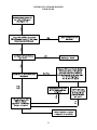
1
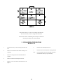
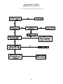
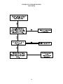
SERVICE MANUAL
FOR
6636A & 6636B SERIES
TWO TON HIGH EFFICIENCY
PACKAGED AIR CONDITIONERS
TABLE OF CONTENTS
1.
2.
3.
4.
5.
6.
7.
8.
8A.
9.
10.
11.
12.
13.
14.
15.
Warnings & Component Match-Up. . . . . . . . . . . . . . . . . . . . . . . . . . . . . . . . . . . . . . . . . . . .
Unit Specifications . . . . . . . . . . . . . . . . . . . . . . . . . . . . . . . . . . . . . . . . . . . . . . . . . . . . . . . . . .
Thermostat Operation & Specifications . . . . . . . . . . . . . . . . . . . . . . . . . . . . . . . . . . . . . . . .
Thermostat Checkout . . . . . . . . . . . . . . . . . . . . . . . . . . . . . . . . . . . . . . . . . . . . . . . . . . . . . . .
Unit Depiction Figures . . . . . . . . . . . . . . . . . . . . . . . . . . . . . . . . . . . . . . . . . . . . . . . . . . . . . . .
Blower Performance Chart . . . . . . . . . . . . . . . . . . . . . . . . . . . . . . . . . . . . . . . . . . . . . . . . . . .
Wiring Diagrams - Electronic Thermostat & A/C Unit . . . . . . . . . . . . . . . . . . . . . . . . . . . .
Wirebox Component Checkout (6636A Series) . . . . . . . . . . . . . . . . . . . . . . . . . . . . . . . . . . .
Wirebox Component Checkout (6636B Series) . . . . . . . . . . . . . . . . . . . . . . . . . . . . . . . . . . .
Indoor Blower Motor Removal . . . . . . . . . . . . . . . . . . . . . . . . . . . . . . . . . . . . . . . . . . . . . . . .
Outdoor Blower Motor Removal . . . . . . . . . . . . . . . . . . . . . . . . . . . . . . . . . . . . . . . . . . . . . . .
Cap Tube Replacement . . . . . . . . . . . . . . . . . . . . . . . . . . . . . . . . . . . . . . . . . . . . . . . . . . . . . . .
Evaporator Coil Replacement . . . . . . . . . . . . . . . . . . . . . . . . . . . . . . . . . . . . . . . . . . . . . . . . .
Condenser Coil Replacement . . . . . . . . . . . . . . . . . . . . . . . . . . . . . . . . . . . . . . . . . . . . . . . . . .
Compressor Replacement . . . . . . . . . . . . . . . . . . . . . . . . . . . . . . . . . . . . . . . . . . . . . . . . . . . . .
Electrical Flow Charts . . . . . . . . . . . . . . . . . . . . . . . . . . . . . . . . . . . . . . . . . . . . . . . . . . . . . . .
2
3
4
5
5
7
7
10
11
12
14
15
16
17
17
18
1. WARNINGS
IMPORTANT NOTICE
WARNING - SHOCK HAZARD
These instructions are for the use of qualified individuals
specially trained and experienced in installation of this type
equipment and related system components.
To prevent the possibility of severe personal injury or
equipment damage due to electrical shock, always be sure the
electrical power to the appliance is disconnected.
Installation and service personnel are required by some states
to be licensed. PERSONS NOT QUALIFIED SHALL NOT
INSTALL NOR SERVICE THIS EQUIPMENT.
CAREFULLY FOLLOW ALL INSTRUCTIONS AND
WARNINGS IN THIS BOOKLET TO AVOID DAMAGE TO
THE EQUIPMENT, PERSONAL INJURY OR FIRE.
NOTE
WARNING
The words “Shall” or “Must” indicate a
requirement which is essential to satisfactory
and safe product performance.
Improper installation may damage equipment, can create a
hazard and will void the warranty.
The use of components not tested in combination with these
units will void the warranty, may make the equipment in
violation of state codes, may create a hazard and may ruin the
equipment.
The words “Should” or “May” indicate a
recommendation or advice which is not
essential and not required but which may
be useful or helpful.
COMPONENT MATCH-UP
1.
6636 Series Package Air Conditioner. (Reference
specifications for model number breakdown and
identification.)
2.
6636-3451 Electronic 12 VDC Wall Mounted
Thermostat. This thermostat is pre-wired to two
electrical connectors. Both the thermostat supply
and control wiring can be quickly attached (plugged
in) to the thermostat.
3.
2
6795B4351 35' thermostat cable with connector plugs
for termination at both the air conditioner and
electronic thermostat.
2. UNIT SPECIFICATIONS
3
3. THERMOSTAT OPERATION AND SPECIFICATIONS
THERMOSTAT OPERATING AND WIRING
REQUIREMENTS
Should the installer desire to hard wire this connection rather
than purchasing the receptacle; the three pin connector can be
cut from the wire ends, the wires stripped and spliced to
complete the required connections. For further wire
identification and function, reference Chart 2.
The 6636 series air conditioner is designed to be operated from
an RV Products electronic wall mounted thermostat. See
component match-up sheet for thermostat part number and
description. The thermostat is designed to operate 12 VDC
controlled heating and air conditioning systems. The
thermostat is designed to operate 12 VDC controlled heating
and air conditioning systems. The thermostat must be
operated from a 12 VDC power source.
CHART 2
The thermostat can control one stage heating and two stages
of cooling. (The thermostat used to operate the 6636 series air
conditioner must be capable of controlling two stage cooling
systems.)
Maximum thermostat output for any load including the furnace
control wire must not exceed one amp.
IMPORTANT
When using wire nuts to complete electrical connections,
always apply a U.L. approved electricians tape and secure the
wire nuts to the wires in a workmanlike manner.
IMPORTANT
Current draws in excess of one amp or
shorting any thermostat wires will cause
permanent thermostat failure.
THERMOSTAT HARNESS
The installer must provide the power source used to operate
both the thermostat and its control circuits. This power
source must provide one amp of continuous current at 12
VDC.
RV Products produces a pre-wired 35' thermostat wiring
harness for this system. See component match-up sheet for
harness part number and description. This harness consists
of the eight wires required for operating the air conditioner and
quick connect receptacles for both the thermostat and the air
conditioner connections.
The thermostat is pre-wired at RV Products with two quick
connect electrical receptacles. There is one 9 pin receptacle
carrying the 8 control wires required to operate the air
conditioner, and a 3 pin receptacle carrying the two power
supply leads and the one furnace control lead.
At the thermostat, the connection is completed with a square 9
pin receptacle that slides together and snap-locks in place.
When making this connection:
The thermostats 9 pin receptacle mates with a receptacle on
one end of the RV Products 35' pre-wired thermostat harness.
See component match-up sheet for harness part number and
description.
The thermostat 3 pin receptacle has no mate in either the
thermostat harness wiring or the thermostat package. Should
the installer desire a total plug in system, then the mate for this
connection will have to be purchased separately. Both the
receptacle and the pins are manufactured by AMP (Aircraft
Marine Products, Inc., Harrisburg, PA). In most cases the
parts can be obtained through a local supply house.
verify that the connectors are properly
aligned
2)
do not use excessive force when joining the
connectors
3)
verify that the connectors have snapped
together on both sides.
The thermostat umbilical attaches to the unit with a rain-tight
fitting. To install, remove the ring-nut from the rain-tight
fitting and insert the wire end and fitting into the hole in the
wirebox side. The ring-nut will now slide over the wire end
and reinstall onto the rain-tight fitting threads. Tighten
securely. The wire end plugs into the receptacle on the
wirebox printed circuit board. Insure that the plug “snaplocks” into the receptacle.
The AMP part numbers are:
1)
2)
1)
3 pin male receptacle #7-480700-0
female pin (for male receptacle) #350218-1
4
Routing of the thermostat wiring harness must comply with all
local and national electrical codes. Collect any excess
thermostat harness in the air conditioner mounting
compartment. Be sure to secure the excess wiring within the
compartment. Coiling the excess harness into 3" diameter
circles or larger is acceptable.
Included in the thermostat installation instructions is a
mounting template to aid in the installation.
IMPORTANT
To reduce the potential for thermostat
failure: always connect the -12 VDC
supply lead to the BLUE wire in the
thermostat 3 pin receptacle before
removing the “anti-static” protective
covering. This will ensure that the
thermostat circuitry is not damaged
by static electricity during installation.
THERMOSTAT MOUNTING
Follow the instructions packed with the thermostat to select a
location for thermostat mounting. Pay particular attention to
choose a location which is not isolated from air currents and
not subject to direct discharge from a cold air register.
4. THERMOSTAT CHECKOUT
1.
Before engaging power to any system, ensure the
following:
A)
All tools have been removed from the
equipment.
B)
All wiring is attached, routed and properly
secured.
C)
All panels (both mechanical and electrical)
are in place.
D)
The thermostat system switch is placed into
the “OFF” position.
E)
2.
3.
Before beginning the checkout procedure,
thoroughly read the checkout instructions in either
the thermostat installation instructions or in the
owners manual provided with this product.
Keep in mind that the wall thermostat provides a
3 minute delay between off and on cycles. A 2.5
minute delay begins both as soon as the compressor
cycles off, and as soon as the thermostat becomes
energized. After completion of the 2.5 minute delay,
an additional 30 second delay will begin as soon as
the thermostat demands cooling.
There is also a 30 second delay between 1st and 2nd
stage cooling. This is to prevent both compressors
from starting simultaneously. To ensure that the
thermostat calls for both 1st and 2nd stage cooling,
verify that the cool setpoint is well below actual
indoor temperature.
All co-workers have been warned that the
equipment is being energized.
System wiring may be checked by referring to the
wiring diagram located on either the back of the
wiring box door or the back of the manual. The wiring
diagram is a total system diagram including the wall
thermostat and air conditioner. The wiring diagram is
drawn so that all wiring box components are shown
“positionally correct”.
4.
After complying with steps 1 through 3, engage
power to all systems and begin checkout procedure.
5. UNIT DEPICTION FIGURES
PACKAGE AIR CONDITIONER MODEL NUMBER BREAKDOWN FOLLOWS:
6
6
3
6
A
8
7
1
12 VDC Control
Sub-Mounted Unit
24,000 BTU
Non-Exhaust
Tecumseh
Compressor
High
Efficiency
PTCR/Start Capacitor
5
FIGURE 1
FIGURE 2
6
6. PACKAGED AIR CONDITIONER BLOWER
PERFORMANCE DATA
TEST CONDITION: 115 VAC, 60 HZ, 1 PHASE, DRY COIL
CHART 1
7. WIRING DIAGRAMS
Diagram 1976G119
Electronic Wall Thermostat Assembly (12 VDC)
7
WIRING DIAGRAM 6636A MODEL
8
WIRING DIAGRAM FOR 6636B MODEL
9
8. WIREBOX COMPONENT CHECKOUT
FOR 6636A SERIES
10
8A. WIREBOX COMPONENT CHECKOUT
FOR 6636B SERIES
11
Plug positions on the p.c. board. If no voltage is detected at the
p.c. board connector, check for voltage at the thermostat.
All functions of this air conditioning unit are subject to thermostat
time delays according to the operation manual.
9. INDOOR BLOWER MOTOR
REMOVAL
1.
It will be necessary to remove the top panel from the
unit.
2.
Remove screws that attach the blower housing to the
end panel.
3.
Disconnect wiring from motor terminal block and
capacitor.
4.
Remove scroll/motor assembly from the unit.
5.
Remove 3 screws from motor mount bracket (See #2,
Figure 7).
12
6.
Remove motor assembly from scroll.
7.
Remove blower wheel and motor mounting bracket.
Note:
Upon reassembly, the references made on Figures 7
and 8 shall be used for proper reassembly.
SIDE VIEW
FIGURE 7
Section 1.
Position motor with terminal block parallel to
motor mount clamp. Assemble motor mount
into scroll in orientation shown.
Section 2.
Torque nut to 65 in. lbs. min.
Section 3.
Ground wire terminal assemblies between
screw head and washer.
Section 4.
Motor rotation wires to be connected:
Yellow to Yellow and Orange to Orange.
Section 5.
Bundle the rotation and capacitor wires up
and wire tie together.
END VIEW
FIGURE 8
13
1.
Wheel must be mounted with a minimum of 5/16"
clearance to scroll sides.
2.
Apply grease to motor shaft before assembling wheel.
3.
Torque set screw on flat of shaft to 110 #10 in. lbs.
10. OUTDOOR BLOWER MOTOR REMOVAL
1.
It will be necessary to remove the top panel of the
unit.
2.
Remove 4 screws that attach scroll housing to side
panel (See #1, Figure 9).
3.
Disconnect wiring from motor terminal block.
4.
Remove scroll/motor assembly from the unit.
5.
If at this point only the blower wheel needs replaced,
then remove 4 screws from inboard venturi. Remove
and replace blower wheel (see note) or else go to Step
6.
6.
Disconnect wiring at capacitor.
7.
Remove 4 screws from venturi (See #1, Figure 10).
8.
Remove 4 screws from motor mount bracket (See #2,
Figure 10).
9.
Remove motor assembly from scroll.
10.
Remove blower wheel and motor mounting bracket.
Note:
Upon reassembly, the references made on Figures 9
and 10 shall be used for proper reassembly.
BOTTOM VIEW
1.
2.
3.
Wheel must be mounted with a minimum of 1/4" clearance to both venturis.
Apply grease to motor shaft before assembling wheel.
Torque set screw on flat of shaft to 110 #10 in. lbs.
14
11. CAP TUBE REPLACEMENT
1.
Remove top panel.
2.
Remove panels from end and side covering
compressors and outdoor blower wheel.
3.
Remove outdoor blower and housing.
A)
4.
Make sure to label the wires of the fan motor
when you take them off.
5.
Unbraze cap tube assembly/assemblies from points
(See #1 and #2, Figure 12). Make note of plumbing
and cap tube locations (the replacement tubes will
have to go back to the same locations).
6.
Cut wire ties holding cap tube assemblies to other
plumbing and remove assembly.
Note:
Be certain at this point that the refrigerant charge has
been removed from the system/systems being
serviced.
15
Upon reassembly, the references made on
Figures 11 and 12 shall be used for proper
reassembly. The assemblies shall be
secured with wire ties in order to prevent
excess chafing and vibration.
12. EVAPORATOR COIL REPLACEMENT
1.
Remove top and side panels next to evaporator.
5.
Remove screws (#4, #5, #6, Figure 12).
2.
Remove refrigerant charge from both systems.
6.
Upon reassembly, the references made on Figure 12
shall be used for proper reassembly.
3.
Unbraze joints #1 and #3, Figure 12.
4.
Remove freeze sensor in evaporator coil.
16
13. CONDENSER COIL REPLACEMENT
1.
Remove top panel.
2.
Remove screws along wirebox side of coil (See #7,
Figure 12).
3.
Remove corner panel (See Figure 12).
4.
Be certain at this point that the refrigerant charge has
been removed from the systems.
5.
Make note of plumbing locations. The plumbing will
have to go back to the same locations on the new
coil.
6.
Unbraze discharge and liquid lines at points #2 and
#9, Figure 12.
7.
Remove condenser coil.
14. COMPRESSOR REPLACEMENT
1.
Remove compressor access panel.
6.
Unbraze plumbing at points #11 and #12, Figure 12
(protect any wiring and insulation from torch flame).
2.
The top panel may be removed at this point if it
allows technicians better access to perform service.
7.
Remove mounting nuts and washers (See #13,
Figure 12).
Remove refrigerant charge from system/systems
being serviced.
8.
Remove compressor from unit.
3.
4.
Remove terminal caps (See #10, Figure 12).
5.
Remove wiring from compressor terminal block (cut
wire ties on suction line).
Note:
17
Upon reassembly, compressor wires shall be
wire tied to suction lines to prevent excess
chafing.
15. ELECTRICAL FLOW CHARTS
6636 SERIES OPERATION SEQUENCE
18
CHECKOUT/NO GREEN L.E.D. LIGHT
FY/F CIRCUIT TO THE THERMOSTAT
Note:
On Model 6636B, the Green L.E.D. has some different functions:
1.
2.
3.
If the light is on solid, then everything is OK.
If the light is blinking slowly, the unit is in a 3 minute time delay.
If the light is blinking fast, there is either no line voltage to Circuit #1 or the freeze thermistor is open.
19
I.D. BLOWER LOW SPEED
THERMOSTAT ON LOW FAN
Note: All operating functions subject to thermostat time delays.
20
I.D. BLOWER HIGH SPEED
THERMOSTAT ON HIGH FAN
Note: All operating functions subject to thermostat time delays.
21
COMPRESSOR #1 CHECKOUT
THERMOSTAT CALLING FOR COMPRESSOR
Note: All operating functions subject to thermostat time delays.
22
COMPRESSOR #2 CHECKOUT
THERMOSTAT CALLING STAGE 2
COOLING ONLY
Note: All Operating Functions Subject To Thermostat Time Delays
23
CHECKOUT OUTDOOR BLOWER
LOW SPEED
24
CHECKOUT OUTDOOR BLOWER
HIGH SPEED
25
RV Products
A Division of Airxcel, Inc.
P.O. Box 4020
Wichita, KS 67204
1976C326 (8-05) PP