1
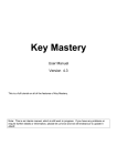
Part 1: Operational Manual Bill Recycler Part-1 Operation Manual (Rev 0) The information contained here-in is the property of Suzo-Happ and is not to be disclosed or used without the prior written permission of Suzo-Happ. This copyright extends to 1. All the media in which this information may be preserved including electronic, printout or visual display. 2. Under no circumstances any part of this publication may be copied, transmitted, transcribed or distributed in any form or by any means, or stored in a database or retrieval system, or translated into any language (natural or computer) without the prior written permission of Suzo-Happ. Rev. 0 -1- © 2014 Suzo-Happ Part 1: Operational Manual 3. Suzo-Happ reserves the right to change the product specifications at any time. Also, Suzo-Happ disclaims any liability for any direct or indirect losses arising out of use or reliance on this information. This information is for guidance only. 4. For any feedback or errors, please contact us at [email protected] H H Revision history Rev 0 Rev. 0 Engineering Nov, 2013 -2- © 2014 Suzo-Happ Part 1: Operational Manual Contents 1. INTRODUCTION: 6 1.1. Glossary: 7 1.2. Safety Instructions: 8 1.3. Product Documentation: 9 1.4. Product Overview: 10 1.4.1. Additional Systems: 10 1.5. Specifications: 12 1.5.1. Overall Specifications 12 1.5.2. Bill Validator Specifications 13 1.6. Compliance Approvals: 15 1.7. Standard Unit Dimensions: 17 1.7.1. Configuration-1: 2 Piece Bezel, 1,000 Cash box 2. MODULAR SYSTEM Rev. 0 17 19 2.1. Description of Modules: 19 2.2. Validating Head: 20 2.3. Sense-A-Click: 21 2.4. Housing: 23 2.5. Bill Validating Head Bezel: 24 2.6. Cash Box: 25 2.6.1. Type of Cash Box : 25 2.6.2. How to Remove the Cash Box: 26 2.6.3. How to collect the bills: 26 2.7. Chassis: 27 2.7.1. 27 Chassis Description: -3- © 2014 Suzo-Happ Part 1: Operational Manual 2.7.2. How to access Chassis Bill Path: 2.8. Recycling Cassette: 29 2.8.1. Recycling Cassette Option: 29 2.8.2. How to remove Recycling Cassette: 30 2.8.3. Manual unloading of Standard Recycling Cassette: 31 2.9. Dispenser: Error! Bookmark not defined. 2.10. Path Switch: 32 2.11. Bill-to-Bill Power Interface: 33 2.12. Control Box: 35 2.13. Accessories: 35 2.14. Memory Card: 36 2.14.1. Memory Card Part Number Legend: 36 2.14.2. Memory Card Options: 36 2.14.3. Memory Card Programming: 37 3. START UP AND INSTALLATION: 38 3.1. Start-up: 38 3.2. Installation of Main Unit: 38 3.2.1. Housing: 38 3.2.2. Two-Piece Bezel Installations: Rev. 0 28 Error! Bookmark not defined. 3.2.3. Grounding: 41 3.3. Security Switch: Error! Bookmark not defined. 3.4. Security Lock Installation: 42 3.4.1. Housing Lock Installation: 42 3.4.2. Chassis Lock Installation: Error! Bookmark not defined. 3.4.3. Cash Box Lock Installation: -4- 43 © 2014 Suzo-Happ Part 1: Operational Manual 3.5. Power & Interface connection: 44 3.5.1. Interface Connection: 44 3.5.2. Signal description for Interface Connection: 44 3.6. Default Settings: 46 3.7. Switch Settings: 46 4. MAINTENANCE AND SERVICE 4.1. E-Learning: 49 4.2. Collect Bills or Barcode Tickets: 50 4.2.1. Standard Cash Box: 50 4.3. Preventative Maintenance: 50 5. SOFTWARE UPDATES: 51 5.1. Memory Card Update Procedure: 51 5.2. Download Procedure Via Interface Connector: 52 5.3. Software Update Diagnostics: 53 6. CONTACT INFORMATION: Rev. 0 49 54 6.1. Technical Support Department: 54 6.2. Service Centers: 54 -5- © 2014 Suzo-Happ Part 1: Operational Manual 1. Introduction: This document is designed to help with the integration of the Bill-to-Bill 200G™ bill recycler. Use this manual for: Rev. 0 Unit dimensions and component nomenclatures, including mounting directions. Bill Recycler specification and configurations, including hardware accessories. General specification for dip switch setting and software updates. Easy Diagnostic for any service requirements. -6- © 2014 Suzo-Happ Part 1: Operational Manual 1.1. Glossary: Anti Stringing Sensor – Sensor used to detect bills being pulled back illegally by using a string, wire or tape. Bar Code Sensor – Sensor to scan bar coded tickets Bezel – Face Plate BV – Bill Recycler or Bill Acceptor Centering Mechanism – Suzo-Happ patented bill centering mechanism which aligns bills before entry into bill path CST – Cassette or Cash Box CPU – Central Processing Unit Dielectric Sensor – Suzo-Happ Patented Sensor used to measure the paper density DIP Switch – Dual Inline Package Switch Bill-to-Bill 200G™ – Suzo-Happ Bill Recycler Memory Card – Portable programmable memory which can used to program BV without any tools Magnetic Sensor – Sensor used to read magnetic properties / ink on the bill Stacker Mechanism – A scissor type attachment used to stack the bill into Cash Box U/V – Ultra Violet Sensor Rev. 0 - Caution / Safety Instructions - Comments / Notes -7- © 2014 Suzo-Happ Part 1: Operational Manual 1.2. Safety Instructions: Please follow the below guidelines: Please make sure the top lid is closed and the 10 pin connector is connected to the Bill-to-Bill 200G™ Recycler before power on. Please follow the specifications for operating temperature, humidity and storage conditions Do not lift or transport the unit by the Cash Box or chassis handle. Be sure to remove power before removing the validating head. Please follow proper cleaning and maintenance procedures, ensuring the performance of the unit. All information about this product is available online, 24 hours a day. Visit our website at suzohapp.com/Bill-to-Bill Rev. 0 -8- © 2014 Suzo-Happ Part 1: Operational Manual 1.3. Product Documentation: Document Type Document Part Numbers Descriptions User’s Guide: UG-MBB-XXXX_Rev XX Hardware Configuration. Software Users Guide: Dip Switch Settings Software Release Specification: SRS MBB-_____-______ Rev XX Standard: Bill Table Reference Diagnostics CRC Bill Set Descriptions: BSD-XXXX-X Picture of Accepted Bills and Denominations for specific software. Cash Box Users Guide: FLSC-XXXX Description and detail of Cash Box and its options. Bezel Users Guide: UG-XXXB-XXXX_X Details of Bezel, opening and mounting arrangement. Operational Manual: Bill-to-Bill 200G_Part1_x Basic Operation Manual for 3D Outline Model: http://elearning.cashcode.com H H Step or IGS format available upon request Contact your sales Suzo-Happ representative. You can also visit our website for available documents. H suzohapp.com/Bill-to-Bill Rev. 0 -9- © 2014 Suzo-Happ Part 1: Operational Manual 1.4. Product Overview: The Bill-to-Bill 200G™ Bill Recycler was developed to validate bills having a width up to 82 mm. Compared to the previous Front Load bill Recycler models, the Bill-to-Bill 200G™ has the following distinctive features: Utilizes a light-weight plastic drop-proof Cash Box 2 Recycling Cassette – up to 110 bill each capacity (Option – Secured lockable) Dispensing bills. The dispense operation is performed through the Validating Head with one bill at-a-time. There is no limit for the number of bills dispensed in one operation; all bills available in the recycling cassettes can be dispensed with one command. The Bill-to-Bill 200G™ BV consists of five main modules. Each module is available in different variations to suit your needs. The picture below illustrates the different modules: The Bill-to-Bill 200G™ recycler is designed to accommodate bills of different sizes from 62 to 82 mm wide, and from 125 to 172 mm long – which represents most of the world currencies. Certain currencies have different widths depending on denomination. For accurate validation of such currencies, the Bill-to-Bill 200G™ Validating Head has a centering mechanism, which aligns the bills for processing of different widths. The lockable-removable Cash Box is used for temporary storage of validated bills. It can be locked with two standard 1-1/8” or 3/4” tubular locks. Bill Capacity (600 or 1,000 banknotes) refers to the number of new bills that the Cash Box can store. Actual Cash Box capacity can decrease in real applications due to variations in thickness of street-grade bills. The Bill-to-Bill 200G™ Housing joins all the other modules. It is meant to be permanently secured inside a host machine. Several Bezel styles are available for the Bill-to-Bill 200G™ recycler. Software updates can be easily uploaded into the Bill-to-Bill 200G™ with a Memory Card or through network. 1.4.1. Additional Systems: The Bill-to-Bill 200G™ product offers two optional systems that expand on the standard features. Secured lockable recycling cassette which prevents access to cash upon removal. Please contact your sales representative for information on either system or sample requests. Rev. 0 - 10 - © 2014 Suzo-Happ Part 1: Operational Manual Exploded view Sense-a-Click Memory Card B2B Power Inrerface Module Validating Head MFL Bezel Chassis Housing Box Control Unit Path Switch Drop Cassette Rev. 0 - 11 - Recycling cassette © 2014 Suzo-Happ Part 1: Operational Manual 1.5. Specifications: 1.5.1. Overall Specifications Bezels and indication: No bezel installed. Green/Red Status Light. Suzo-Happ Style (Plastic or Metal) Standard: Optional Bezel: Acceptance: Bills: Lengthwise 4 ways Accepted Denominations: Refer to Software Description Guide Validating Rate: 96% or higher (on first insertion) Supported Bill Width (mm): 62 ~ 82 Length of Bill supported(mm): 120 ~ 172 Bill Storage: Number of Recycling Cassette : 2 Recycling Cassette Capacity : 80 ~ 110 bills (depends on bill lengths) Number of Cash Box : 1 Cash Box Capacity : 600 / 1,000 bills Dispensing Ability: One bill at-a-time Bar Code Tickets: Lengthwise 2 ways face up only (refer to settings). Bar Code Specification: Encoding standard: ANSI/AIM BC2-1995, Uniform Symbology Specification – Interleaved 2 of 5 Narrow bar width, in mm: 0.5 to 0.6 Wide/Narrow bar ratio: 3:1 Number of characters: 6 to 18 PCS (Print Contrast Signal) value: 0.6 min Installation: Any FrontLoad application. For Backload requirement please use rotational mounting elements. Access to Cash Box: From front side of the Recycler. Rev. 0 - 12 - © 2014 Suzo-Happ Part 1: Operational Manual Outter Dimensions: (H x W x D) Plastic single bezel with standard Cash Box capacity (1000 capacity) 1.5.2. Bill Validator Specifications Validation Sensors: 3-Color Reflective Optical Sensors: 3 Sets on top, 3 set on bottom 1-Color Translucent Optical Sensors: 3 on top Dielectric Sensors: 1 (Differential) Inductive Sensors: 3 Anti Stringing Sensors: 1 Set Barcode Sensors: 2 (Upper cover) U/V Sensors: 1 Interface connector: Standard: 10-pin power and signal connector. Supported Protocols and Interfaces: Universal Platform: Bi-Directional EIA-232C (RS 232) CCNET (Proprietary Serial Protocol) Service indication: Flashing of LED or the bezel lights. Memory programming: Suzo-Happ Memory card Interface controlled with NDEG card installed Supported memory stick types: Hex format (Stay-in or Multi-update) NDEG Mode selection: 8 pack + 4 pack - position DIP switch Power supply voltage: 24 VDC ±5% Operating Voltage: Current (Standby)* Rev. 0 - 13 - © 2014 Suzo-Happ Part 1: Operational Manual Ambient temp (+5C or higher) 0.6 Amp Ambient temp (-30C ~ + 5C) 0.6 ~ 2.2 A Average 2.4 A Current Operating Mode (Peak) Peak (Spikes 100 ms) 4 A Validating Head Outer Dimensions: (H x W x D) 96 mm x 115 mm x 234 mm (3.78 inch x 4.52 inch x 9.22 inch ) Standard Cash Box Specifications Cash Box locks: Standard: No locks installed, only cams supplied. Shipped with shipping lock and cap. Cash Box Free Fall Test: Functional Height: 1 meter. (Standard: IEC 68-2-32: 1975) Number of falls: 14 (6 sides, 6 edges, 2 corners) Maximum stacking capacity: (new bills) Up 1000 banknotes Outer Dimensions: (H x W x D) 600 Banknote Cash Box: 188 mm x 104 mm x 173 mm (7.42 inch x 4.09 inch x 6.83 inch) 1000 Banknote Cash Box: 188 mm x 104 mm x 233 mm (7.42 inch x 4.09 inch x 9.18 inch) Unit Weight: 600 Banknote Cash Box (Empty): 1.1 Kg (2.42 lb) 100 Banknote Cash Box (Empty): 1.4 Kg (3.08 lb) Rev. 0 - 14 - © 2014 Suzo-Happ Part 1: Operational Manual 1.6. Compliance Approvals: CE Marking & Compliance ElectroMagnetic Compatibility (EMC) CISPR 22:2005/EN 55022:2006 (+A1) ITE – Radio disturbance characteristics CISPR 24:1997/EN 55024:1998 (+A1 +A2) ITE – Immunity characteristics Safety ITE – Low voltage directive EN 60950-1:2006 (+A1:2010, +A11:2009, +A12:2011) UL Certificate UL 756 Coin & Currency changers and actuators Environment Operating environment…..……………....................................... Indoor or environmentally protected stationary applications Operating Temperature for Bill-to-Bill unit……………….............................…………..….. 0C to +50C Optional security features Drop cassette……………………………………….................................… one or two ¾” tubular locks Housing………………………………………….................................…….…one ¾” tubular lock for drop cassette Rev. 0 - 15 - © 2014 Suzo-Happ Part 1: Operational Manual Optional features: Vandalism-proof metal bezel for validating head Vandalism-proof metal bezel with heating element for dispenser Drop cassette equipped with tracking system Contact your sales representative for details. Rev. 0 - 16 - © 2014 Suzo-Happ Part 1: Operational Manual 1.7. Standard Unit Dimensions: 1.7.1. Configuration-1: 2 Piece Bezel, 1,000 Cash box Bill-to-Bill 200G™ BV without Bezel, Foldable Handle Cash Box (600 Bills): 12.05 [0.47"] 76.15 [3.00"] 82.5 [3.25"] 267 [10.51"] Ø6 [Ø0.24"] 101 [3.98"] 6 [0.24"] 5.2 [0.20"] 5 [0.20"] C 11 [0.43"] 55.5 [2.19"] Ø6 [Ø0.24"] 88 [3.46"] Mounting holes Front panel thk 6mm max 337.7 [13.30"] 480.25 [18.91"] 11 [0.43"] A 3 mounting holes for M5 screw 64.5 [2.54"] 5 [0.20"] 1.5 [0.06"] 212.4 [8.36"] A 217.2 [8.55"] 277.3 [10.92"] 230.15 Side View Cash Box Clearance Table TVM Door Thickness Dimension C FLSCX0102 Flex Handle Rev. 0 FLSCX0101 Folded Handle 3 mm 6.35 mm 14.75 mm 4 mm 5.35 mm 13.75 mm 5 mm 4.35 mm 12.75 mm 6 mm 3.35 mm 11.75 mm - 17 - © 2014 Suzo-Happ Part 1: Operational Manual 168 [6.61"] 157.4 [6.20"] 137.5 [5.41"] 561 [22.09"] 104.2 [4.10"] 155 [6.10"] Front View All dimensions are in mm (inches in brackets) and are for reference only. Rev. 0 - 18 - © 2014 Suzo-Happ Part 1: Operational Manual 2. Modular System 2.1. Description of Modules: The Bill-to-Bill 200G was built on modularity principles. The Bill-to-Bill 200G consists of the following modules: Validating Head/Dispenser – accepts and validates legitimacy of bill, also used for dispensing bills Bezel – Seven different bezels are available—however, bezels with a digital display are recommended (for Software update and diagnostics via a service keypad) Sense-a-Click™ sensor pack – Four version as are available depending on currency set Power Interface Module - Only one variety may be used with the B2B Cash Box - Secure Cash Box, it is referred to as a “drop cassette”. 4 Choices: 600 / 1000 and type of handle Memory Card - is universal for all Suzo-Happ products Housing – 2 types (Exterior – Metal version or Interior – Plastic bezel version) Chassis – 1 type Recycling Module – Consists of a total of three recycling cassettes: 2 Choices a) Basic – Can access the money, b) Lockable – Can not access the money by hand, if detached. Path Switch – 1 type Bill-to-Bill Box Control Module – 1 type Rev. 0 - 19 - © 2014 Suzo-Happ Part 1: Operational Manual 2.2. Validating Head: Lift the latch to open the guide Lift the latch to release from the housing The Bill-to-Bill’s validating head features self-centering transport guides, which perfectly align multi-width and skewed bills. The width of the bill path automatically adjusts to accommodate each bill. Accessing bill path: There are two guides in the validating head that must be opened to access the bill path. If space above the Bill-to-Bill allows, the guides in the validating head can be opened without removing the validating head from the housing. Otherwise the validating head must be removed from the housing. To remove the validating head from the housing lift the latch at the bottom of the validating head and pull out the validating head. To open the guides lift the latch at top of each guide and rotate the guides as shown in figure below. Rev. 0 - 20 - © 2014 Suzo-Happ Part 1: Operational Manual Part Number Description MFLV-9013 Multi-width centering mechanism 2.3. Sense-A-Click: “Sense-a-Click” sensor packs are a set of two modules—one upper and one lower. In order to be compatible with each other, both modules must have the same part and model number. The Sense-a-Click set is identified by: Color and position of the optical sensors Number and position of the inductive sensors Capacitive sensors Model, which reflects the type of electronics housed therein, and determines the compatibility with other modules Upper module Rev. 0 Lower module - 21 - © 2014 Suzo-Happ Part 1: Operational Manual Sense-a-Click sensor pak (upper) Sense-a-Click sensor pak (lower) Depending on the bill country type, the following Sense-a-Click part numbers should be used: Currency Argentina Australia Brazil Canada Chile China China + Hong Kong Colombia Dominican Republic European Union (Euro) Euro + Swiss + Reka Great Britain Hong Kong India Kazakhstan Rev. 0 AR AU BR CA CL CN CNHK CO DO EU EUCHRK GB HK IN KZ Part Number for Sense-a-Click Sensor Packs Set of Two Upper Module Lower Module Modules FLS-1704/1706 FLS-1704/1706U FLS-1704/1706L FLS-1704/1706 FLS-1704/1706U FLS-1704/1706L FLS-1704/1706 FLS-1704/1706U FLS-1704/1706L FLS-1801 FLS-1801U FLS-1801L FLS-1704/1706 FLS-1704/1706U FLS-1704/1706L FLS-1705/1707 FLS-1705/1707U FLS-1705/1707L FLS-1705/1707 FLS-1705/1707U FLS-1705/1707L FLS-1704/1706 FLS-1704/1706U FLS-1704/1706L FLS-1704/1706 FLS-1704/1706U FLS-1704/1706L FLS-1704/1706 FLS-1704/1706U FLS-1704/1706L FLS-1704/1706 FLS-1704/1706U FLS-1704/1706L FLS-1704/1706 FLS-1704/1706U FLS-1704/1706L FLS-1705/1707 FLS-1705/1707U FLS-1705/1707L FLS-1705/1707 FLS-1705/1707U FLS-1705/1707L FLS-1704/1706 FLS-1704/1706U FLS-1704/1706L - 22 - © 2014 Suzo-Happ Part 1: Operational Manual Currency Mexico New Zealand Philippines Russia Scotland South Africa Ukraine USA USA + Canada USA + Great Britain USA + Mexico Venezuela 2.4. MX NZ PH RU SL ZA UA US USCA USGB USMX VE Part Number for Sense-a-Click Sensor Packs Set of Two Upper Module Lower Module Modules FLS-1705/1707 FLS-1705/1707U FLS-1705/1707L FLS-1704/1706 FLS-1704/1706U FLS-1704/1706L FLS-1704/1706 FLS-1704/1706U FLS-1704/1706L FLS-1704/1706 FLS-1704/1706U FLS-1704/1706L FLS-1704/1706 FLS-1704/1706U FLS-1704/1706L FLS-1704/1706 FLS-1704/1706U FLS-1704/1706L FLS-1704/1706 FLS-1704/1706U FLS-1704/1706L FLS-1704/1706 FLS-1704/1706U FLS-1704/1706L FLS-1901 FLS-1901U FLS-1901L FLS-1704/1706 FLS-1704/1706U FLS-1704/1706L FLS-1704/1706 FLS-1704/1706U FLS-1704/1706L FLS-1705/1707 FLS-1705/1707U FLS-1705/1707L Housing: The Housing is made of a rigid metal structure, which allows you to mount the Recycler using the left, right or back side. The Bill-to-Bill housing carries all of the modules and cables necessary for interconnections. The housing is the only module in the Bill-to-Bill that is permanently installed inside a cabinet. There are security switches in the housing: 1. “Cash Box removal”, 2. “Cash Box lock open”, (if the locking mechanism for the drop cassette is present), For switch connection, please refer to the “INSTALLATION SECURITY FEATURES”. Depending on the supporting bracket for the drop cassette, the following implementations of the housing are available: Part Number BBH-5515 BBH-5516 Rev. 0 Bezels Configuration for metal bezel Configuration for plastic bezel - 23 - Cash Box size 600 / 1000 600 / 1000 © 2014 Suzo-Happ Part 1: Operational Manual 2.5. Bill Validating Head Bezel: The Bezels are U/L and CE compliant and 85 mm wide opening. Multiple bezel designs make the Crane Payment Solutions Bill-to-Bill 200G™ Bill Recycler compatible with a wide variety of door styles. Part Number Picture Description Standard Coin Proof Metal Bezel This bezel requires additional grounding hardware on the unit housing. Please see the Bezel User Guide for mounting instructions. MFLB-7102 Plastic Bezel MFLB-6101 No Grounding required If you have custom bezel requirements, please contact your Suzo-Happ Sales Representative Rev. 0 - 24 - © 2014 Suzo-Happ Part 1: Operational Manual 2.6. Cash Box: 2.6.1. Type of Cash Box : The Cash Box stores, stacks and holds validated bills in a secure cassette. The Cash Box has a stacking mechanism and is typically equipped with a latch. Users are encouraged to replace the latch with a regular metal Bill-to-Bill200G. Users have a choice between Bill-to-Bill 200G or two locks for added security. A locking mechanism allows for the installation of security locks (Bill-toBill 200G or two 3/4” tubular locks measuring 11/16” ± 1/16” or 1 1/8” ±1/16”). All security locks are supplied by user. Although Cash Boxes are available in 600 or 1000 storage capacity, street grade bills require more space and as a result full capacity may be reduced. The Cash Box can store bills from 60 to 85 mm wide and from 120 to 172 mm long. FLSC-0001* 600 Capacity, Foldable Handle FLSC-0101* 1000 Capacity, Foldable Handle FLSC-0002 600 Capacity, Flexible Handle FLSC-0102 1000 Capacity, Flexible Handle *Special Order For other drop cassettes please contact the Suzo-Happ Customer Service department. Rev. 0 - 25 - © 2014 Suzo-Happ Part 1: Operational Manual 2.6.2. How to Remove the Cash Box: 1) Open the lock in the housing (if equipped) 2) Push the release button Grasp handle and pull out the drop cassette 1. Open the Lock with the Key 2. Pull out the Drop Cassette 2.6.3. How to collect the bills: 1. Unlock 1 (or 2 locks) and open the cover 2. Remove bills Rev. 0 - 26 - © 2014 Suzo-Happ Part 1: Operational Manual 2.7. Chassis: 2.7.1. Chassis Description: The chassis carries 3 recycling cassettes, one dispensing cassette, and one path switch. It also has drive arrangements—for transporting bills, recycling cassettes, and positioning the path switch—as well as connection cables and a local controller. Part Number Number of Recycling Cassettes BBC-0110 Can accommodate up to 3 Recycling Cassettes Removing the Chassis from the Housing Unlock the tubular lock at the front of the dispensing module (if present) Push the release bar under the validating head Pull out the chassis 1. PUSH THE BAR TO RELEASE THE CHASSIS HANDLE 2. PULL OUT THE CHASSIS USING THE HANDLE Caution! The chassis may be heavy to handle! Support the module beneath the chassis with one hand. Rev. 0 - 27 - © 2014 Suzo-Happ Part 1: Operational Manual 2.7.2. How to access Chassis Bill Path: Press either release button and pull open the machine. The gas spring supports the chassis in the opened position. The opened chassis also allows access to the path switch. The chassis can be opened with, or without, the recycling and dispensing cassettes present. Path Switch Push release button to open the Chassis Optical sensors Fig. 5 Fig. 6 Rev. 0 - 28 - © 2014 Suzo-Happ Part 1: Operational Manual 2.8. Recycling Cassette: 2.8.1. Recycling Cassette Option: The Bill-to-Bill carries up to three recycling cassettes, which operate identically. Built with flexibility in mind, the user can program which bill denominations will be used in each of the recycling cassettes. The maximum storage capacity of each cassette ranges from 80 to 110 bills. The exact number of bills that can be stored is dependent upon the bill length: the shorter the bill, the higher the number of bills that can be placed inside the cassette. A flash memory inside each recycling cassette stores information on the number, and denomination of bills housed in the cassette. The flash memory prevents operation errors from occurring, i.e.: when a cassette is installed in a random position in the Bill-to-Bill. Rev. 0 Part Number Type Bill storage capacity BBR-0110 Standard 80 – 110 BBR-0111 Lockable 80 – 110 BBR-0112 Standard (Narrow Tape) 80 – 110 BBR-0113 Lockable (Narrow Tape) 80 – 110 - 29 - © 2014 Suzo-Happ Part 1: Operational Manual 2.8.2. How to remove Recycling Cassette: Remove the chassis from the Bill-to-Bill housing first (see section entitled “chassis”) Slide the latch on the chassis (each cassette has its own latch) and pull out the cassette Slide the latch Pull out the cassette Fig. 8 Rev. 0 - 30 - © 2014 Suzo-Happ Part 1: Operational Manual 2.8.3. Manual unloading of Standard Recycling Cassette: Please note that this section apply for only standard recycling cassette. For lockable cassette following procedure is not applicable. Open the cover Plastic handle Pull the latch Rotate the plastic knob in counter-clockwise direction. Bills are manually dispensed one bill at a time. Should a jammed bill be located in the entrance slot, this bill can be easily removed without adversely affecting the later operation of the cassette. Please note: manually unloading bills will reduce the number of bills in the cassette, without changing the number of bills in flash memory. It is strongly recommended to perform a complete unload operation, after the cassette is replaced in the Bill-to-Bill (please see the “Unloading Options” section). This will allow the Bill-to-Bill to readjust the flash memory when the cassette is operational again. Do not attempt to pull out the white tapes present in the cassette! This could damage the cassette! Rev. 0 - 31 - © 2014 Suzo-Happ Part 1: Operational Manual 2.9. Path Switch: The path switch organizes connections between modules via various bill paths. Possible bill path directions are: from validating head to recycling cassette 1 from validating head to recycling cassette 2 from validating head to recycling cassette 3 Validating Head Recycling Cassette 1 from validating head to drop cassette from recycling cassette 1 to validating head from recycling cassette 2 to validating head from recycling cassette 3 to validating head from recycling cassette 1 to drop cassette from recycling cassette 2 to drop cassette from recycling cassette 3 to drop cassette Part Number Number of connected paths BBS-0110 5 Recycling Cassette 2 Drop Cassette Path Switch Removing the Path Switch: Remove the chassis from the housing first (please see section above) Rev. 0 Open the chassis Pull the tab and rotate the bearing 90 degrees, Repeat the action with the second bearing at the opposite side of the chassis Once both bearings have been released, carefully pull out the path switch from the chassis - 32 - © 2014 Suzo-Happ Part 1: Operational Manual 1. Pull the tab 2. Rotate the bearing 90° 3. Remove the Path Switch Maintenance of the Path Switch: The maintenance of the path switch is recommended approximately two times per year. Preventative Maintenance includes visual inspection of belts. There must be no cracks on the surface of the 8 timing belts, and no visible damage of the components. The path switch organizes connections between modules via various bill paths. 2.10. Bill-to-Bill Power Interface: The Bill-to-Bill power interface module is placed in the housing at the left side of the validating head. It carries connectors for all external connections to the Bill-to-Bill. Rev. 0 - 33 - © 2014 Suzo-Happ Part 1: Operational Manual Power and interface Part Number Interface Power BBP-5713 RS232 (CCNet) 24V DC Removing the Bill-to-Bill Power Interface Module: Remove the screw under the Bill-to-Bill power interface at the front side Pull the latch of the Bill-to-Bill power interface module to remove it from the housing 2. Pull the latch 1. Remove screw Rev. 0 - 34 - © 2014 Suzo-Happ Part 1: Operational Manual 2.11. Control Box: This unit helps in cash box function and stacker motor control. 2.12. Accessories: Please order necessary accessories based on your need. Accessories P/N Description OPT-PS-BB-CCNET 24 Volt power supply for Bill-to-Bill 200G OPT-HS-BB-CCNET Power interface cable OPT-CLEAN-KIT-1 Level 1 maintenance kit OPT-CLEAN-KIT-2 Level 2 and 3 maintenance kit OPT-BB-SP3 Consumable replacement kit for BB maintenance (screws, bearings and push rivets) OPT-BB-SP4 Hardware replacement kit for level 2 BB maintenance OPT-BB-SP5 Hardware replacement kit for level 3 BB maintenance Rev. 0 - 35 - © 2014 Suzo-Happ Part 1: Operational Manual 2.13. Memory Card: Each Suzo-Happ Bill-to-Bill 200G™ Bill Recycler is supplied with pre-installed software or a Stay-In Memory Card (for gaming applications), according to users order. A Stay-In Memory Card may be a single download, a Bill-to-Bill 200G time programmable, or an NDEG card. Software updates are recommended whenever: New currency is issued, or A new series of counterfeit bills are discovered. 2.13.1. Memory Card Part Number Legend: BBXM-31EU1100 Type 31 Memory Card: (P1848-FLM31) BBXM – Standard Bill-to-Bill 200G™ BV Memory Card Dallas Chip, 128 K Memory 31 – Type of memory card (see table) EU – Country code (ISO 3166-3) 1 – Protocol/OEM Customization To be available Software version: 1 – Protocol (1 for CCNET) 1 – OEM Customization 00 – Firmware Revision CPU Chip, 128 K Memory Type 40 Memory Card (P1848-FLM40) Memory Card Type Mfg. Download Single Download* MultiDownload NDEG Chassis 31 X X X √ √ 40 √ √ √ √ X 2.13.2. Memory Card Options: Single Download (Stay-In) Memory Card: Example Part Number: BBXM-40EU1501 New software can be ordered on single-download Memory Cards. The software from the new Memory Card is downloaded as soon as it is inserted into the slot, and the Validating Head is powered on. The Memory Card must be present at all times for the Bill Recycler to operate. The Stay-In/Single Download update scheme is recommended option only for applications where 3rd party verification is required. Rev. 0 - 36 - © 2014 Suzo-Happ Part 1: Operational Manual NDEG (Stay-In) Memory Card: Example Part Number: BBXM-31C02-NDEG A special Memory Card can be ordered, which allows the download of new software through the interface connector. After the download, the Memory Card must be present in the Validating Head at all times. If the host controller supports the CCNET interface, then the download can be done via the host controller (and local network). Other interfaces do not support this download feature. Downloads in this case can be completed with any personal computer (PC or laptop) and a Crane Payment Solutions adapter. (The Recycler must be temporarily disconnected from the host controller). Multiple Download Card: Example Part Number: BBXM-31EU1500-XX New software can be ordered with a multi-download Memory Card. The multi-download Memory Card can be used for updating multiple Bill-to-Bill 200G™ Bill Recycler, depending on the number of licenses ordered. Subsequently, the card does not have to remain inside the unit during operation. Typically a multi-download Memory Card is issued for a limited number of downloads (maximum 99), and therefore the number of licenses required must be defined in the user’s order. Procedures for software updates can be found in section 5. 2.13.3. Memory Card Programming: There are several tools available to program memory cards with the appropriate software. Software upgrades are ordered through the Suzo-Happ customer service department. P1848 Single-Card Programmer P3418 Multi-Card Programmer (Mobile) For information, operational instructions and availability please contact your Suzo-Happ sales representative. Rev. 0 - 37 - © 2014 Suzo-Happ Part 1: Operational Manual 3. Start Up and Installation: 3.1. Start-up: To avoid damage of any kind during start-up process, please carefully check all points specified below: 3.2. Make sure to use proper cable harness based on interface and cabinet. Power supply must conform to the specification on the label. Proceed as follows to install the Bill-to-Bill 200G™ Bill Recycler in the main cabinet. Installation of Main Unit: 3.2.1. Housing: The Bill-to-Bill 200G™ Bill Recycler is installed by using M5 screws on each side of the Front Load frame. In addition, two holes at the bottom are provided for better alignment of product, we suggest our customer to install Alignment Pin as suggested in the figure below. The length of these screws should not be longer than required. Otherwise they may protrude through the inside of the frame. We also recommend using the spacers for additionally support the unit as indicated in below figure. If the position of the mounting screws is different than the position of the mounting holes provided in the target equipment, then additional frame mounting components may be required. For dimensions of the mounting holes, please refer to the dimensional drawings. Please see the appropriate User Guide for your Bezel to ensure proper grounding & installation instruction. M5 fasteners (metric) or 10-24 (imperial) should be used Rev. 0 - 38 - © 2014 Suzo-Happ Part 1: Operational Manual Rev. 0 - 39 - © 2014 Suzo-Happ Part 1: Operational Manual Installation View 3 Mounting Points Side Bracket Bill-to-Bill 300 XE Detailed View A Spacer 90 ° Max. 8 mm A Alignment Pins √ Side Mounting and Mounting Pin on the bottom 3 Mounting Points Side Bracket Bill-to-Bill 300 XE Detailed View A Spacer ° 90 Max. 8 mm A Alignment Pins √ Side Mounting and Mounting Pin on the bottom 6 Mounting Points Side Bracket Side Bracket Bill-to-Bill 300 XE Spacer A Max. 8 mm 90 ° Detailed View A √ Side Mounting on Both Side and Mounting Pin on the bottom Recommended Mechanical Installation Method Rev. 0 - 40 - © 2014 Suzo-Happ Part 1: Operational Manual 3.2.2. Grounding: Protective-earth ground terminal must be connected to the automat grounding bus or terminal. Protective earth connection must be made by cable OPT-MKSM-GND or another cooper wire cable with wire gage 14…12 AWG. Use the shortest, practical wire length but no more than 1.5 meters. Refer to local codes and regulations for grounding requirements. In our design, DC power supply lines, interface lines are separated from chassis / Protective earth ground / Safety Ground. Each manufactured device are passes Production Hi-pot test. Screw M4 Lock Washer M4 Protective Earth Cable Housing Grounding Rev. 0 - 41 - © 2014 Suzo-Happ Part 1: Operational Manual 3.3. Security Lock Installation: The Bill-to-Bill Currency Management System has several security features. The drop cassette can be locked with Bill-to-Bill 200G or two ¾” tubular locks. The drop cassette can be also locked to the housing with a ¾” tubular lock. There can be two security switches: Billto-Bill 200G detects the presence of the drop cassette in the housing, and another detects that the housing lock is secured in “locked” position. The chassis within the recycling and dispensing cassettes can be locked in the housing with a ¾” tubular lock, positioned 5/8” from the mounting surface to a latch. The provision for the lock is located in the dispensing cassette. Neither recycling cassettes nor dispensing cassettes can be removed from the chassis, until the cassis is not removed from the housing. 3.3.1. Housing Lock Installation: Remove the screw and lock washer from the lock cover. DO NOT DISCARD! Remove and discard the washer and spacer Install the lock and parts, as shown below Install the cover, screw and lock washer that were removed Bushing BB01.16.134 (5210082) Remove parts of shipping latch DOM Lock 225-08 Camlock 1 81" Camlock 78" Camlock 58" Bushing BB01.16.133 (5210080) Install Lock Bushing BB01.16.135 (5210081) Housing Lock Installation Rev. 0 - 42 - © 2014 Suzo-Happ Part 1: Operational Manual 3.3.2. Cash Box Lock Installation: In order to install the security locks into the Cassette, open the Cassette cover, remove the plastic lock and plug, and follow the diagram shown below: Due to variation of regulatory requirement, Suzo-Happ does not provide locks but we provide cam and applicable washers as accessories. K C O L N U Hex Nut Washer Hasp (5110086) K C O L N U Nut Cassette Our design supports 1. Up to 2 locks 2. 2 sizes (5/8" or 1-1/8") 3. Suitable manufacturers include MEDECO, KABA, ABLOY, VSR, Bilock Washer Lock Cover O19.05 [3/4"] 9 max 15.88 [5/8"] A O22.2max O7.14 [9/32"] 5.56 [7/32"] 3.03 max A=5 8" or A=118" In order to lock, they must rotate in opposite directions (Bill-to-Bill 200G lock 90 degree clockwise and second should be 90 degree counterclockwise see figure above. Two locking hasps are shipped with every cassette – P/N - 5110086 Standard Detailed Dimension of Slot for Lock Rev. 0 - 43 - © 2014 Suzo-Happ Part 1: Operational Manual 3.4. Power & Interface connection: The Bill-to-Bill 200G™ Bill Recycler has following protocol/interface options: RS232 levels (CCNET) 3.4.1. Interface Connection: The Bill-to-Bill power interface module has the following external connections: X2, Molex p/n 43650-1000 (module portion) For detailed CCNET interface descriptions, please refer to the corresponding Interface (Protocol) Description Manual. The manuals may be downloaded from theSuzo-Happ website at suzohapp.com/Bill-to-Bill/. H 3.4.2. Signal description for Interface Connection: TERMINAL Rev. 0 SIGNAL FUNCTION 1 POWER + (24 V DC) POWER 2 POWER + (24 V DC) POWER 3 POWER (0 V) POWER 4 POWER (0 V) POWER 5 CHASSIS Functional Earth 6 CHASSIS Functional Earth 7 RXD Host serial receive 8 TXD Host serial transmit 9 Not in use Not in use 10 GND Interface common - 44 - © 2014 Suzo-Happ Part 1: Operational Manual The lengths of power and interface cables should not exceed 10 meters Power and interface cables do not connect to outdoor communication links and to outdoor DC current lines. The interface cable must be shielded. The shield is connected to pin 6 of connector X2. The shield of another cable end is connected either to the case of Host or to the grounding bus or terminal of the automat near to Host Controller. Any of the communication cables must be either rated 20, 22 or 24 AWG. The power cable to use fourth core cable connected to pins 1, 2, 3 and 4 of connector X2. Each wire section should be no lesser than AWG20 (e.g. 22 AWG is not acceptable). From the direction of the power supply the wires are connected in pairs. Rev. 0 - 45 - © 2014 Suzo-Happ Part 1: Operational Manual 3.5. Default Settings: The following are the default Bill-to-Bill settings: 3.6. The switch setting (on the validating head) is in “validation mode”; all denominations are enabled; the bill orientation is set to four-ways, and the interface communication speed is 19200 BPS. Recycling cassettes are pre-programmed for the three lowest bill denominations (assuming there are no special requirements in a User’s order). The unload level for the recycling cassettes is “0”. The automatic unload time for the recycling cassettes are “indefinite”. Switch Settings: The DIP switches are located at the rear of the validating head, under the transparent cover. Switches SW1 SW2 Rev. 0 - 46 - © 2014 Suzo-Happ Part 1: Operational Manual The Bill-to-Bill operates in two basic modes: validation mode and service mode. Validation mode: This is the mode for normal operation. If a red status light is illuminated, this indicates that the bill validator is not ready to accept currency. Service mode: This is the mode for software update and testing the Suzo-Happ bill validator. A series of 8-position DIP switches (SW1) define the settings and program the bill validator is to recognize, in order to validate a variety of bill denominations. ON 1 2 3 4 5 6 7 8 Parameter Switch On Off Denomination #1 SW1.1 Enabled Disabled Denomination #2 SW1.2 Enabled Disabled Denomination #3 SW1.3 Enabled Disabled Denomination #4 SW1.4 Enabled Disabled Denomination #5 SW1.5 Enabled Disabled Denomination #6 SW1.6 Enabled Disabled Denomination #7 SW1.7 Enabled Disabled Acceptance Mode SW1.8 Accept All Reject Unfit Bills DIP switch setting may vary based on software requirement for specific country or customer. For complete explanation of switch settings, please refer to “software version description” for your articular Bill Recycler. You can find at suzohapp.com/Bill-to-Bill/ Rev. 0 - 47 - © 2014 Suzo-Happ Part 1: Operational Manual The 4-position DIP switches (SW2) are defined below: ON 1 2 3 4 Parameter Switch Orientation of the ticket SW2.1 Four-way One-way SW2.2 Reserved Reserved Interface communication speed SW2.3 9600 BPS 19200 BPS Mode SW2.4 Service Mode Validation Mode Rev. 0 - 48 - On Off © 2014 Suzo-Happ Part 1: Operational Manual 4. Maintenance and Service 4.1. E-Learning: Suzo-Happ offers interactive online and video training for installation, maintenance, update, and service procedures for the Bill-to-Bill 200G™ Bill Recycler. Please see suzohapp.com/Bill-to-Bill/ for up-to-date training videos and instructions. H H Some content will require you to create an account with Suzo-Happ support. Please register at suzohapp.com/Bill-to-Bill/ or contact [email protected] for quick & easy access! Rev. 0 - 49 - © 2014 Suzo-Happ Part 1: Operational Manual 4.2. Collect Bills or Barcode Tickets: To collect bills from the Bill-to-Bill 200G™ Bill Recycler, simply pull out the Cash Box using the handle. To open the Cash Box cover, open the locks located at the two corners. To replace the Cash Box, close the cover and insert the Cash Box into the Bill-to-Bill 200G™ housing. 4.2.1. Standard Cash Box: 4.3. Preventative Maintenance: During normal operation, dust and dirt accumulate on the optical sensors and the rollers of the validating head, Dispenser, Chassis and Cash Box, possibly resulting in a reduced acceptance rate or jam reliability. Please refer to the serviceability manual for additional information on the frequency of cleaning and the procedures to be followed while maintaining the unit. Rev. 0 - 50 - © 2014 Suzo-Happ Part 1: Operational Manual For interactive training on maintaining your Bill-to-Bill 200G™ Bill Recycler, please see the suzohapp.com/Bill-to-Bill/ website. H H For further advanced maintenance detail, please ask your sales representative. 5. Software Updates: The Bill-to-Bill 200G™ Bill Recycler is shipped with pre-installed software, according to a user’s ordered specifications. It is recommended to keep your BV up to date. You can order updates from Suzo-Happ as they become available using the original part number for your system. 5.1. Memory Card Update Procedure: 1. Turn Power OFF. 2. Lift up the Latch under the Validating Head, and Remove the Validating Head from the Housing. 3. Insert the new Suzo-Happ Memory Card into the Memory Card slot of the Validating Head (for correct insertion, please see diagram below). Memory Stick Label should face up and notch on memory stick should face the right side 4. Insert the Validating Head into the Housing. 5. Turn Power ON and wait until the download process is completed. During the download, a redgreen status light will blink. Once the download is completed, the diagnostic light will turn green. If the light stays red, please refer to the next section “Software Update Diagnostics” 6. After the update, a single-download Memory Card must be present in the Bill Recycler at all times during operation. A multiple-download card can be removed and used to update more units, until the number of licenses is reached. Rev. 0 - 51 - © 2014 Suzo-Happ Part 1: Operational Manual 5.2. Download Procedure Via Interface Connector: In order to properly complete an interface download, the Network Download Enable Memory Card must be present in the Memory Card slot at all times – before, during and after the download. For a direct download in the service mode via the interface connector, please follow the instructions below: 1. Turn power OFF. 2. Disconnect the interface connector from the Bill Recycler. 3. Remove the Validating Head from the Housing, and set Mode Switch to Service mode (Refer to section 3.7). 4. Install the Validating Head into the Housing. 5. Connect the Crane Payment Solutions Adaptor: a) to the Computer, b) to the interface connector of the Bill Recycler, and c) to the power outlet (AC 100-250V). 6. From the computer, run the latest software version of the program. 7. Follow the instructions displayed on the computer screen. 8. After completing step 7, disconnect the Suzo-Happ Adaptor: a) from the power outlet, b) from the Bill Recycler, and c) from the Computer. 9. Remove the Validating Head from the Housing, and set Mode Switch to Validation mode (refer to section 3.7). 10. Install the Validating Head into the Housing. 11. Connect the interface connector to the Bill Recycler. When the Bill-to-Bill 200G™ Bill Recycler has a CCNET protocol, the software download can be completed via the host controller (refer to CCNET Protocol Description). Rev. 0 - 52 - © 2014 Suzo-Happ Part 1: Operational Manual 5.3. Software Update Diagnostics: Normally, the download process will be accompanied by a blinking red-green status light for about 1 minute. If the download has competed successfully, the status light will turn green. Should the download be unsuccessful, the status light will turn red, with short green flashes. The following table lists possible errors which may take place during a download: Green Flashes Error Solution 1 green flash on red External interface error in CCNET download mode 1. Verify that software is suitable for CCNET download. 2. Repeat procedure. 2 green flashes on red Memory card CRC error 1. Turn power OFF, remove and reinsert the memory card, turn power ON. 2. Replace memory card with a new one. 3 green flashes on red Incorrect data in memory card 1. Verify that the software is suitable to the B2B type. 2. Insert correct type of Crane Payment Solutions memory card. 4 green flashes on red Memory card is not inserted Properly insert the memory card. 5 green flashes on red Wrong type of memory card Insert the correct type of Crane Payment Solutions memory card. 6 green flashes on red Failure during download 1. Turn power OFF, remove and reinsert the memory card, turn power ON. 2. Replace memory card with a new one. 7 green flashes on red Operation error of memory card interface 1. Turn power OFF, remove and reinsert the memory card, turn power ON. 2. Replace memory card with a new one. Rev. 0 - 53 - © 2014 Suzo-Happ Part 1: Operational Manual 6. Contact Information: 6.1. Technical Support Department: Suzo-Happ 587 Hanlan Drive, Woodbridge, ON, L4L 4R8 Phone: 1-800-239-7017 (+1-905-851-4702) +1-905-303-8875 E-mail: [email protected] H Website: 6.2. suzohapp.com/Bill-to-Bill Service Centers: To locate your nearest service center, please check our website: suzohapp.com/Bill-to-Bill Rev. 3 - 62 - © 2014 Suzo-Happ