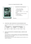
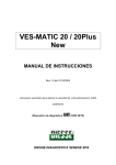
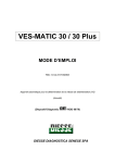
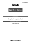
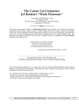
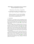
1
DIESSE DIAGNOSTICA SENESE S.P.A.
VES-MATIC 20
VES-MATIC 20 PLUS
Service Manual
Release 1.00 - English
Automatic instrument for the determination of the erythrosedimentation rate (ESR)
(patent pending)
The information contained in this manual can be subject to modification without notice. Any of the parts of this manual can
be reproduced in any way or media electronic or mechanical, for any use, without the written authorisation of Diesse
Diagnostica Senese S.p.a.
Copyright © October 2001. Diesse Diagnostica Senese S.p.a. All rights reserved.
2
TABLE OF CONTENTS
1.
VES MATIC 20 / VES MATIC 20 PLUS
INTERVENTION PROCEDURES (TROUBLE SHOOTING) ............................................p.5
1.1.
1.2.
1.2.1.
1.2.2.
1.2.3.
1.2.4.
1.2.5.
Approach to the VES MATIC 20 / VES MATIC 20 PLUS instrument
Analysis of the faults
The instrument does not switch on
The instrument switches on / Self test
The instrument switches on / Display
The instrument switches on / Printer
The instrument switches on / Check Device
2.
PROCEDURE TO DISMOUNT
THE ROTATION MOTOR GROUP - SAMPLE HOLDER PLATE.................................p.11
3.
PROCEDURE TO REASSEMBLE
THE ROTATION MOTOR GROUP - SAMPLE HOLDER PLATE.................................p.12
4.
PROCEDURE TO CALIBRATE THE VES MATIC 20 / 20 PLUS INSTRUMENT
FOLLOWING DISMOUNTING OR FOLLOWING A PERIODICAL CHECK-UP ......p.13
5.
PROCEDURES TO FOLLOW FOR INTERVENTIONS ON THE DIFFERENT
MODULES ................................................................................................................................p.19
5.1.
5.1.1.
5.1.1.1.
5.1.1.2.
5.1.2.
5.1.3.
5.1.4.
5.1.4.1.
5.1.5.
5.1.6.
SERVICE MANUAL THE POWER SUPPLY MODULE...................................................p.19
General
Aim
Applicability
Relative documentation
Relative instrumentation
Trouble shooting
Description of the module
Flow Chart no. 2
Access to the module
Appendix A: Examination of the faults
5.2.
5.2.1.
5.2.1.1.
5.2.1.2.
5.2.2.
5.2.3.
5.2.4.
5.2.4.1.
5.2.5.
5.2.6.
SERVICE MANUAL CPU MODULE ...................................................................................p.33
General
Aim
Applicability
Relative documentation
Relative instrumentation
Trouble shooting
Description of the module
Flow Chart no. 3
Access to the module
Appendix B: Examination of the faults
3
5.3.
5.3.1.
5.3.1.1.
5.3.1.2.
5.3.2.
5.3.3.
5.3.4.
5.3.4.1.
5.3.5.
5.3.6.
SERVICE MANUAL DISPLAY/KEYBOARD MODULE ..................................................p.47
General
Aim
Applicability
Relative documentation
Relative instrumentation
Trouble shooting
Description of the module
Flow Chart no. 4
Access to the module
Appendix C: Examination of the faults.
5.4.
5.4.1.
5.4.1.1.
5.4.1.2.
5.4.2.
5.4.3.
5.4.4.
5.4.4.1.
5.4.5.
5.4.6.
SERVICE MANUAL PRINTER INTERFACE MODULE .................................................p.59
General
Aim
Applicability
Relative documentation
Relative instrumentation
Trouble shooting
Description of the module
Flow Chart no. 5
Access to the module
Appendix D: Examination of the faults.
5.5.
5.5.1.
5.5.1.1.
5.5.1.2.
5.5.2.
5.5.3.
5.5.4.
5.5.4.1.
5.5.5
5.5.6.
SERVICE MANUAL MOTORS AND CONTROLS BOARD MODULE .........................p.73
General
Aim
Applicability
Relative documentation
Relative instrumentation
Trouble shooting
Description of the module
Flow Chart no. 6
Access to the module
Appendix E: Examination of the faults.
Appendix F:
CONNECTION TO A HOST COMPUTER AND SPECIFICATIONS OF THE
COMMUNICATIONS PROTOCOL FOR VES-MATIC 20 / VES MATIC 20 PLUS
Appendix G: CONNECTION OF A BARCODE READER TO INSTRUMENTS OF THE VES LINE
Appendix H: FIRMWARE UPGRADE FOR THE VES MATIC 20 AND VES MATIC 20 PLUS
INSTRUMENT
Appendix I:
LAYOUT FOR ELECTRONIC CONTROL BOARD AND SCHEMATICS
4
1.
VES MATIC 20 / VES MATIC 20 PLUS - INTERVENTION PROCEDURES
(TROUBLE SHOOTING)
Before performing any type of intervention on the instrument:
a) SWITCH OFF THE ON/OFF SWITCH ON THE VES MATIC INSTRUMENT.
b) DISCONNECT THE INSTRUMENT FROM THE POWER SUPPLY IN ORDER TO
AVOID ANY RISK OF CONTACT WITH ELECTRICAL OR MECHANICAL PARTS
UNDER LINE VOLTAGE.
IF THESE BASIC RULES ARE NOT FOLLOWED, THE MANUFACTURER OF THE
VES MATIC 20 / VES MATIC 20 PLUS INSTRUMENT WILL ACCEPT NO
FURTHER RESPONSABILITY.
1.1.
APPROACH TO THE VES MATIC 20 / VES MATIC 20 PLUS INSTRUMENT
1. Observe the recommendations reported in paragraph 1.
2. Open the outer covering of the instrument.
3. Gain access to the module of interest, as described in the procedures reported
hereafter (see Flow Chart no. 1).
VES MATIC 20
VES MATIC 20 PLUS
Type of Fault
Analisys of
fault OK
N
S
Dissasembly of the module
(Dismounting Procedures)
Intervention on the Module of
Interest (Trouble Shooting)
Reassembly of the Module of
Interest
(Reassembly Procedures)
Retesting of the Module of
Interest
(Calibration Procedures)
Flow-chart n°1
5
1.2.
ANALYSIS OF THE FAULTS
The faults reported in the following paragraphs make reference to the Trouble Shooting
procedures described for the individual modules, in order to demonstrate the type of
approach to follow in these situations.
1.2.1. The instrument does not switch on
a) Check that the mains power supply is working.
b) Check the power cable.
c) Check the fuses at the back of the instrument.
d) Check the ON/OFF switch on the back of the instrument.
e) Check the Power supply module (see procedure regarding Power supply).
1.2.2. The instrument switches on / Self Test
The instrument is switched on but the Self-Test is performed incorrectly, gives Error
codes, or is not performed at all.
a) The Self-Test is not performed
Check that the cover is closed - Close the cover.
Check the I/O board (see 5.5. procedure).
Check the CPU board (see CPU procedure).
b) The Self-Test is performed incorrectly - Error codes are visualized.
During the Self-Test the following Error Messages may appear on the display:
1) Error reading
Error in reading of the Motor
Error in reading of the Home sensor (see 5.5. procedure)
Check the Home Sensor (see 5.5. procedure).
Check the Motors and Controls Board (see 5.5. procedure).
2) Error plate
The sample plate holder does not move up and down
Check the UP/DOWN Sensor controlling the plate position (see 5.5. procedure)
Check the cabled Motor-reducer (see 5.5. procedure)
Check the Motors and Controls Board (see 5.5. procedure)
3) Error Mixing
The Sample holder plate does not rotate
Check the Plate Motor (see 5.5. procedure)
Check the Plate Home Sensor (see 5.5. procedure)
Check the Home sensor stirrup (see 5.5. procedure)
Check the Motors and Controls Board (see 5.5. procedure)
4) Check Device exhausted
The Check Device is not working
Check the Check Device (see 5.5. procedure)
Check the Motors and Controls Board (see 5.5. procedure)
6
1.2.3. The unit is on/display
a) The display visualizes but does not illuminate (backlighting )
b) The display does not visualize but illuminate
c) The display does not visualize and does not illuminate
d) The display visualize but the data can not be entered with the keyboard
See Display/Keyboard module procedure (5.3.).
1.2.4. The instrument switches on / Printer
a) The paper is not fed in; the printer does not print.
b) The paper advances but the printer does not print.
c) The printer prints but the paper does not advance correctly.
d) The printer prints in the compressed form.
e) The printer prints the wrong characters (see Printer procedure 5.4).
1.2.5. The instrument switches on / Check Device
a) The Check Device does not charge
Check that the Check Device is inserted correctly:
- Switch off the instrument
- Insert a new Check Device in the Check Device holder with the label facing the
operator (see operator manual, Check device procedure)
- Switch on the instrument.
If all is KO, check the Motors end Controls Board (see 5.5. procedure).
7
EXPLODED VIEW AND PART LIST TABLE
8
161
033
046
034
084
035
159
044
043
158
045
095
160
081
157
066
083
042
156
036
041
040
064
037
037
095
065
149
150
085
082
154
149
153
151
095
152
039
155
038
Esploso M eccanica VES-M ATIC 20 N ew - Pag.1/4
10
109
008
056
090
107
203
091
108
075
202
007
105
001
072
074
002
053
073
092
052
099
051
093
106
092
054
096
097
006
055
047
104
093
094
049
094
050
048
104
005
103
099
102
137
101
100
003
Esploso M eccanica VES-M ATIC 20 N ew - Pag.2/4
11
12
098
020
122
061
123
098
132
095
078
060
125
146
147
004
017
016
077
019
018
062
060 124
126
060
148
131
129
130
141
128
127
145
021
136
022
138
063
023
079
031
024
032
025
026
144
030
095
080
139
027
029
143
139
140
141
142
028
095
062
Esploso M eccanica VES-M ATIC 20 N ew - Pag.3/4
135
137
139
13
110
011
Esploso M eccanica VES-M ATIC 20 N ew - Pag.4/4
095
010
009
076
012
114
011
086
112
111
113
015
111
112
115
121
116
120
014
117
059
118
119
059
14
208
206
200
217 201
219
204 205
212
218
207
211
203
9
2
C
ES
IN T
6
PR
5
1
FE
ED
0
ST
D IS
P
C
LO
TE
7C
3
K
ME
OK
8
4
NU
209
213 214
215
202
210
216
30002870 – Ves-Matic 20 New
30002570 – Ves-Matic 20 Identisystem
30002830 – Ves-Matic 20 Plus
Part list
Position
Code
Description
Note
001
002
003
004
005
006
007
008
009
010
011
012
013
014
015
016
017
018
019
020
021
022
023
024
025
026
027
028
029
030
031
032
033
034
035
036
10325860
10128470
10301290
10126400
10327500
10325871
10327880
10323970
11504520
10325530
10325521
10118881
30401950
10330790
10330790
30204440
10325581
10127530
10125590
10327540
10325551
10327850
10119081
30204660
10125610
10118941
10118951
10325571
30401731
30204650
30204680
10325630
10601340
10127240
10328100
10802110
Case power supply
Insulator pad for power supply
Ves20 painted tray
V20 pivot plate
Ves20 new base plate
Support for power supply
Carter riser in/out
Card support oxy/opto
Spheric bearing SKF GE 8 C
Upsetting pivot bush
Ves20 fixed stirrup
Square photocell activation
Motorid. TRIAL mod.
Mechanical axis support
Mechanical axis support
Ves20 complete plate
Rotation pivot plate
V20 friction plate
Reset plate photocell support
Cover drive card
Moving mechanic support
Support guide reading
Group guide reading
Group slide reading
Read_home square
Square fixing belt
Plate belt clamp
Motor reading supprt
Tractor pulley undercarriage resding
Pulley group
Group support reading guide
Reading sensor fixing plate
Ves20 plastic bubble
Bubble’s zipper V20
Bubble’s strapV20
Ves20 adhesive product
15
Position
Code
Description
Note
037
038
039
040
10127270
10325840
10127910
1110F35Z
041
042
043
044
045
046
047
048
049
050
051
052
053
054
055
056
057
058
059
060
061
062
063
064
065
066
067
068
069
070
071
072
073
074
075
076
077
10301330
10328090
10126750
30204720
10127260
10301280
10325850
30112281
1110030Z
1110F56Z
11141172
30112050
30114070
30114100
10328490
30113480
V20 bubble zipper guide
Half-case/microswitch support
V20 glass display
Würth 0683-284-3 (single) self-adhesive
buffer
Ves20 painted up case
V20 painted box printer
Paperbreaking
Assembly fulcrum zipper printer cover
Printer cover zipper
V20 painetd printer cover
CPU protection case
CPU board Ves30/Ves20 Rev.01
Hexagonal spacer
STEAB 5021/3////06 spacer
Screw M3x6 UNI 7687 inox
Cabled bar-code reader
Fun cooler V30/V20 new
Flash board writer rev.01vers.V30&V20new
Flash writer fixing plate
Signals board IN/OUT RS485/prog
30114060
30111640
30111650
30114050
30112310
30113470
30113750
30111340
Motoreducer. cabl.traslation V30/V20 new
Ves 20 Cabled photocell board
Motors diver board
Cabled Reading motor./agitat. V30/V20 new
Reading sensor board
Ves20 keyboard
Interf. board display+keyb. Ves20
Small printer board. WT01
21440230
21200540
20892130
1110010Z
1110584R
1110008Z
Supply. Mean-Well PT65-D (+5/+12/+24)
Black bip.int OMEGA I4700 16A/250V
Mains input plug ACTRONIC AR-09-2F-6A
STEAB 5021/5////05 spacer
Seeger ring E 8 UNI 7435
ELESA B193/15P-M4x10 knob
16
Position
Code
Description
Note
078
079
080
081
082
083
084
085
086
…
…
089
090
091
092
093
094
095
096
097
098
099
100
101
102
103
104
105
106
107
108
109
110
111
112
113
114
115
116
117
118
1110010Z
1110675Z
11712010
12500290
21200680
21430120
12300010
10326070
10125620
STEAB 5021/5////05 spacer
Benzing ring 6 UNI 7434-75
1056 MXL 025 (svil. 268,386) belt
Zipper art. 101 30x30 nikel.
Microswitch Honeywell V5C010BG1L
11141394
1110023Z
1110024Z
1114473L
11141394
1114544Z
1114499Z
1110H65Z
1110F30Z
11141182
11160971
11141934
1114B39Z
1114505Z
1114B62Z
1114474L
11141183
11141183
20814070
11141272
11141182
11141172
1114476L
1114549Z
11141394
11141183
11141424
11141383
11141376
1114501Z
Screw M4x10 UNI 5931 inox
Hexagonal spacer F-F M3x30
Hexagonal spacer M-F M3x20
Nut M3 UNI 5588 inox
Screw M4x10 UNI 5931 inox
Rosetta 4x12 inox
Rosetta 3,2x7 UNI 6592 inox
PrinterPANAS.EPL-1902S2AE(PAN-MEC000200)
Termal printer roll l=58 mm
Plate microswitch
Bush of beat
DIST.ESAG. F-F M2 E.ZUB. FF10 H 2040 12
Hexagonal spacer M-F M3x12
Screw M3x8 UNI 7687 inox
Screw M2x5 UNI 6109 Ot
Screw M6x10 UNI 5931 inox
Rosetta A6,4 UNI 1751 grover inox
Rosetta 6,4x12,5 UNI 6592 inox
Rosetta dentellata A4,3 DIN 6798 inox
Nut M4 UNI 5588 inox
Screw M3x8 UNI 7688 inox
Screw M3x8 UNI 7688 inox
Kit col.fiss.conn.vasch. M/F nikel L=7
Screw M3x30 UNI 7687 inox
Screw M3x8 UNI 7687 inox
Screw M3x6 UNI 7687 inox
Nut M6 UNI 5588 inox
Washer 6x18 inox
Screw M4x10 UNI 5931 inox
Screw M3x8 UNI 7688 inox
Screw M4x16 UNI 5931 inox
Screw M4x8 UNI 7688 inox
Screw M4x6 UNI 5923 inox
Washer 4,3x9 UNI 6592 inox
17
Position
Code
Description
Note
119
120
121
122
123
124
125
126
127
128
129
130
131
132
133
134
135
136
137
138
139
140
141
142
143
144
145
146
147
148
149
150
151
152
153
154
155
156
157
158
159
11141394
1114474L
1114501Z
1110026Z
1110027Z
11141404
11141192
1110021Z
11141402
1114B37Z
1114501Z
11141174
1114501Z
1110389G
Screw M4x10 UNI 5931 inox
Nut M4 UNI 5588 inox
Washer 4,3x9 UNI 6592 inox
Hexagonal spacer M-F M3x30
Hexagonal spacer M-F M3x10
Screw M4x12 UNI 5931 inox
Screw M3x10 UNI 7687 inox
Hexagonal spacer M-F M3x15
Screw M4x12 UNI 7687 inox
Washer A4,3 UNI 1751 grover inox
Washer 4,3x9 UNI 6592 inox
Screw M3x6 UNI 5931 inox
Washer 4,3x9 UNI 6592 inox
Screw PZAB 2,9x6,5 UNI 6954 Zn
11141402
1114501Z
11141173
11141173
11141174
1114501Z
1114B37Z
11141394
11141176
11141092
11141484
1110460Z
11141242
11141376
1110459Z
11141242
11141192
11141224
1110389G
1110F42Z
1110009Z
11141182
1110391H
1110383G
1110381G
Screw M4x12 UNI 7687 inox
Washer 4,3x9 UNI 6592 inox
Screw M3x6 UNI 7688 inox
Screw M3x6 UNI 7688 inox
Screw M3x6 UNI 5931 inox
Washer 4,3x9 UNI 6592 inox
Washer A4,3 UNI 1751 grover inox
Screw M4x10 UNI 5931 inox
Screw M3x6 UNI 5923 inox
Screw M2,5x6 UNI 7687 inox
Screw M4x30 UNI 5931 inox
Nut autoblocking M4 UNI 7473 Zn
Screw M3x20 UNI 7687 inox
Screw M4x6 UNI 5923 inox
Nut autoblocking M3 UNI 7473 Zn
Screw M3x20 UNI 7687 inox
Screw M3x10 UNI 7687 inox
Screw M3x16 UNI 5931 inox
Screw PZAB 2,9x6,5 UNI 6954 Zn
Hexagonal spacer M-F M4x15
Washer STEAB 5015/4/1//16
Screw M3x8 UNI 7687 inox
Screw PZAB 2,9x13 UNI 6955 Zn
Screw PZAB 2,2x6,5 UNI 6954 Zn
Screw PZAB 2x5 UNI 6954 Zn
18
Position
Code
Description
Note
160
161
162
163
164
165
166
167
168
169
170
…
…
…
11141172
11141183
Screw M3x6 UNI 7687 inox
Screw M3x8 UNI 7688 inox
-------------------- Cables list--------------------------------Position
Code
Description
Note
200
201
202
203
204
205
206
207
30113870
30114280
30114270
30114260
30114250
30114240
30114300
30114080
Signals motors driver cable V30/V20 new
Flash writer cable Ves20
Seriale cable RS232C V20
Barcode reading cable ext. V20
Seriale connection cable RS485 V20
Internal programm. Cable ISP V20
Ground cable L=400 O/O
External programming cable V30&V20 e
Optional
208
209
30113840
30114000
210
211
212
30113990
30114290
30113890
213
214
215
216
217
218
30114020
30114010
30114190
30114230
30113930
30113940
219
30113980
Printer cable V30/V20 new
Power supply cable 90/264Vac Ves30/Ves20
new
Power supply cable CPU/fan V30/V20 new
Interface cable display+keyb. V20
Power supply cable motors drivers V30/V20
new
Neutral cable pin/filter Ves30/Ves20 new
Fase cable pin/filer Ves30/Ves20 new
Ground cable L=150 O/F
Ground cable L=250 O/F
Microswitch cover cable Ves30
Internal cable connection bar code reader
V30 new
External cable connection barcode reader
V30/V20 new
19
2.
PROCEDURE TO DISMOUNT
THE ROTATION GROUP-SAMPLE HOLDER PLATE (see figure of exploded views)
Proceed step by step as reported below
a)
Follow the recommendations in paragraph 1 points a) and b)
b) Unscrew the 5 screws (pos. 089) on the base’s external sides.
c)
Open the outer covering (Pos. 041), lifting the front part and rotating it towards, be carefull
to don’t damage the internal cables.
d) Unscrew with a key the screw (Pos. 077) that bolcks the sample holder plate ( pos. 016)
e)
Remove the sample holder plate (Por. 016)
e) Now we have at totally disposition the instrument’s mechanics for any intervention
3.PROCEDURE FOR REASSEMBLY OF THE ROTATION GROUP-SAMPLE
HOLDER PLATE
Follow the procedure reported below:
3.
To go backward in the procedure reported at the point N 2.
20
4.
CALIBRATION PROCEDURE OF THE UNIT VES MATIC 20 /VES MATIC 20
PLUS AFTER THE DISASSEMBLY OR FOR THE PERIODICAL PROTOCOL.
When the unit is assemblied back keeping the carter opened:
Access to the instrument keeping pressed the button “0” of the keyboard, the instrument
pages to automatically in “TEST FACTORY”.
With this menù we can do test and calibration of the instrument.
Test Factory
On the diplay appears :
VES MATIC 20 NEW
TEST FACTORY
and the printer makes the print below:
******************
*
FACTORY TEST
*
******************
-
CONTROLS –
(1) = SERIAL RS232
(2) = TEMPERATURE
(3) = CLOCK
(4) = TRANSLATOR
(5) = PLATE
(6) = SENSOR READING
(7) = ID. SETTING
(8) = CARD
(9) = BARCODE
(OK) = STRESS PLATE
-select pressing the button “1” the voice “SERIAL RS232”
Serial Protocol
1= OLD
21
2= NEW
Pressing the button “1” of the keyboard we select the dates trasmission like on the old
instruments Ves Matic 20/60 on the display appears:
Serial Protocol
OLD PROTOCOL
Pressing the button “2” of the keyboard we select the new dates trasmission on the display
appears:
Serial Protocol
NEW PROTOCOL
Pressing the button “OK” we confirm the effected selection.
-select pressing the button “2” the voice “TEMPERATURE”
TEMPERATURE
20
In this way appears the temperature read to the instrument, if it was different as that present in
the environment operate with the trimmer RV2 placed on the cpu board (Pos. 042) turning it
in clockwise we growing up the temperature, in anticlockwise it reduces it. Pressing the button
“OK” we come back to the menù “TEST FACTORY” and the printer prints the temperature
value put:
******************
* TEMPERATURE TEST
*
******************
TEMPERATURE
20
-select pressing the button “3” the voice “CLOCK TEST”
DATE DD/MM/YEAR
30/10/2001
22
Pressing the button “ESC” we cancel the set up date and we place the instrument for the
insertion of the new date, on the display appears:
DATE DD/MM/YEAR
/
/20
Pressing the numerical buttons we insert the day, the month then the last two figures that
indicate the year.
Ex. We want to insert the date 1st Aprile 2002
Press:
For the day:
Button ”0”
Button“1”
For the month
Button “0”
Button “4”
For the year
Button “0”
Button“2”
pressing the button “OK” we confirm what we have pressed, automatically the instrument
places itself in the menù for to put back the hour and on the display appears:
TIME HH:MM:SS
09:46 :11
Pressing the button “ESC” we cancel the date fixed and we put the instrument for to insert the
new date,on the display appears:
TIME HH:MM:SS
_ :
:
Pressing the numerical buuttons we insert the hours ,the minutes, then the seconds.
23
Ex. We want to insert the following time 08:50:52
Pressing:
For the hours:
Button”0”
Button “8”
For the minutes:
Button “5”
Button “0”
For the seconds:
Button“5”
Button “2”
Pressing the button “OK” we confirm what we have pressed, automatically the instrument
updates the time , the date an the printer prints :
******************
*
CLOCK TEST
*
******************
DATE (dd/mm/yy) 01/04/2002
TIME (hh:mm:ss)
08:50:52
-select pressing the button “4” the voice “TRANSLATOR” on the display appears:
VES MATIC 20 New
TEST TRASLATOR
Automatically the instrument makes the upsetting sample holder plate until the shaking
position after a few seconds it gets it in the vertical .
In this way we check the right working of the system and at the end the printer makes the report
print:
******************
*
TRANSLATOR TEST
*
******************
24
TRANSLATOR
OK
If there were some faultes the printer prints the following report:
******************
*
TRANSLATOR TEST
*
******************
TRANSLATOR
KO
If test “KO” verify what below:
a) That there weren’t mechanic impediments for the traslation group rotation.
b) That to the motor (Pos. 059) the tension arrives (we read only a medium tension because
the motor is drove in PWM, about 6 Volt)use a tester for to verify.
c) Verify the photocelles functionality (Pos. 060)
d) If the points a, b, c are ok continue to the CPU board replace (pos. 048) look procedure
chapter 5.2 .
-select pressing the button “5” the voice “PLATE” on the display appears:
PLATE HOME
STEP: 008
The printer prints in the following report:
******************
*
PLATE TEST
*
******************
PLATE
OK
The value that appears on the display corresponds to the step number that the machine has as
ofset than the home plate sensor (Pos. 060/019). The ofset means to fix the position 1 of the
sample holder plate (Pos. 016) than the reading sensor.
Pressing the button “5 Up arrow” we grow up the ofset of 2 steps, and pressing the button “6
Down arrow) we grow down the ofset of 2 steps. The smallest removing value of every buttons
pression “5” and “6” is of two steps. Pressing the button “OK” the instrument makes a new
25
sample holder plate rotation and places itself on the new ofset set up. The display shows the
new set up value. Pressing the button “ESC” we get out from the procedure and we come back
to the menù “TEST FACTORY”
-select pressing the button “6” the voice “SENSOR READING” on the display appears:
SET SENSOR
1-AUTO ; 2-MANU
Pressing the button“1” we place the sensor test in automatical way.
The instrument makes a reset of the sampleholder plate placing the cuvette 1 in correspondence
with the reading sensor, and asks the insertion of a new cuvette with latix calibration 3, insert
the cuvette and press the button “OK” (we suggest to close the door for not have external light
interferences). The instrument makes some readings until when reducing the current on the
emitter sensor doesn’t pierce the latix to 3. On the display appears a trimmer calibration value
(about 20).
At this time the instrument asks to insert a cuvette with calibration latix 2, insert a cuvette and
pressing the button “OK”.
The instrument makes some readings until when regulating the current on the emitter sensor
doen’t pierce the latix to 2. On the display appears for a moment the trimmer calibration value
(about 40), then appears the medium value which comes calibrated the sensor, in the indicated
values as the example results to be 30.
Pressing the button “2” we place the manual sensor test.
The instrument makes reset turn of the sample holder plate positioning the cuvette 1 in
correspondence of the sensor reading, and shows the trimmer calibration value. Insert one
cuvette with the latix calibration 3, press the button “TEST”, the instrument makes a reading
that has to give the state sensor in light . For to found the limit point change the placed value
with the button “5 UP ARROW “ for to grow up and “6 DOWN ARROW” for to grow down
and press the button “TEST” to make the reading .
Remove the cuvette and insert the cuvette with latix calibration 2 , pressing the button
“TEST” the instrument makes a reading tha has to give for result the sensor state in dark, for
to found the limit point change the placed value with the buttons “5 UP ARROW” for to grow
up and “6 DOWN ARROW” for to grow down, then press the button “TEST” for to make the
reading.
-select pressing the button “7” the voice “ID. SETTING” on the display appears:
26
VES MATIC 20New
Select ID: 01
This setting is for the connection of more instruments through the serial door RS485 (min. 1
instrument, max. 32 instruments), with the program Ves-PC for Dos as a max. 6 instruments.
The default’value is 01 (low value), we can change with the buttons “5 UP ARROW” for to
grow up and “6 DOWN ARROW” until the value of 32. At the end of the selection press the
button “OK”the printer prints the following report:
******************
*
SELECT ID
*
******************
Number ID :
1
-select pressing the button “8” the voice “CARD” on the display appears:
INSERT CARD…….
Press a Key
With this menù we can check the right work of the check device reader or of the paper that acts
to check device. Insert the Check Device in the special place, with the arrow put in the
direction of the instrument and the white side with Diesse green logotype in up direction. Press
a button’s keyboard and on the diplay appears :
RECHARGE CHECK ?
04000
Pressing the button “OK” we have the reloading of 4000 strokes of the check device, pressing
the button “ESC” we get out from the menù without reloading the 4000 strokes of the check
device in the instrument’s memory. If we insert a check device without strokes on the display
appears:
27
CARD EXAUSTED!
00000
-select pressing the button “9” the voice “BARCODE” on the display appears:
VES MATIC 20New
COD:
With this
menù
we can verify the
barcode working for the instruments in version
IDSYSTEM. After the selection the instrument overturns the sample holder plate in a way it
can take it in the bar code reading position, pressing the button “5 UP arrow” we make turn
the sample holder plate of one position in anticlockwise, pressing the button “6 DOWN arrow”
we make turn the sample holder plate of one position in colckwise.
After have placed a cuvette with the bar code in front of bar code press the button “3 TEST”
for to turn on the reader if it comes read on the display appears in clear the barcode value.
Pressing the button “ESC” we get out from the menù and we come back TEST FACTORY
-select press the button “0”the voice “STRESS READING” on the display appears:
VES MATIC 20New
TEST FACTORY
The instrument makes a reset of sample holder plate in a way to place the cuvette 1 in
correspondence of the reading sensor and starts to make slide the reading sensor trolley for all
the run. This test is useful in disassembly and assembly case of the reading group, in way to
verify in automatic the right movement. Fot to finish the test press the button “ESC”.
-select pressing the button “0” the voice “STRESS PLATE” on the display appears:
VES MATIC 20New
TEST FACTORY
The instrument makes a reset of the sample holder plate in a way to place the cuvette 1 in
correspondence of the reading sensor and starts to make wheel the sample holder plate in every
28
position, at every stop comes made a trolley reset, that brings the reading sensor. This test is
useful in assembly and disassembly case of the sample holder group plate for to verify in
automatically the right movement. For to finish the test press the button “ESC”.
29
5.
PROCEDURES TO FOLLOW FOR INTERVENTIONS ON THE DIFFERENT
MODULES
5.1.
5.1.1.
5.1.1.1.
5.1.1.2.
5.1.2.
5.1.3.
5.1.4.
5.1.4.1.
5.1.5.
5.1.6.
SERVICE MANUAL THE POWER SUPPLY MODULE (Pos. 072)
General
Aim
Applicability
Relative documentation
Relative instrumentation
Trouble shooting
Description of the module
Flow Chart no. 2
Access to the module
Appendix A: Examination of the faults
30
5.1.
SERVICE MANUAL THE POWER SUPPLY MODULE (Pos. 072)
5.1.1.
General
5.1.1.1.
Aim
The present document furnishes details of the Trouble Shooting procedures
regarding the Power supply module (Pos. 072), assembled on the VES MATIC 20 /
VES MATIC 20 PLUS instrument.
5.1.1.2.
Applicability
The recommendations contained in the present document are applicable for use in
the final service check-up to ascertain the acceptability of the instrument.
5.1.2.
Relative documentation
20102900
5.1.3.
Scheme of the VES MATIC 20 / 20 PLUS system (in the current edition).
Relative instrumentation
Multimeter Mod. FLUKE 8010A or equivalent.
Philips Laboratory Oscilloscope or equivalent.
Standard laboratory welder.
3-4 mm screw-drivers, pliers, standard laboratory tools.
5.1.4.
Trouble shooting
5.1.4.1.
Description of the module
The power supply form has made from a multifrequency multitension switching
power supply that distributes the right tensions for the instrument working.
The tensions accepted in entry are:
Vca from 90 to 264 Volt
Work frequency from 44 to 440 Hertz
P Max d.c 65 Watts
The tensions supplied in exit are the following:
+5 Vdc n°1 red cable
+12 Vdc n°1 orange cable
+24 Vdc n°1 blu cable
Gnd
n°3 black cable
55
5.1.5.
Flow Chart no. 2
Trouble shoooting phase in relation to the Power Supply module (Pos. 072).
Power supply
Check Power
On Fuse
Fuse
OK ?
N
Change the fuse
S
Check the supply
Cable
Cable OK ?
N
Change the supply
Cable
S
Change power supply
Board
56
5.1.6.
Access to the module
a)
Disconnect the VES MATIC 20 / VES MATIC 20 PLUS instrument from the power
supply, as reported in paragraph 1.
b)
Remove the outer covering as reported in paragraph 2 in order to gain access to the
internal parts.
c)
Unscrew the screw and remove the case (pos. 001)
d)
Disconnect the cable connected on Power Supply (pos. 209, 210, 216)
e)
Unscrew the Hexagonal spacer (pos. 090 and 091).
f)
Remove the Power Supply module board.
g)
Replace the faulty power supply board whith another new.
57
Appendix A: Examination of the possible faults
The examination of the main defects is performed according to the table reported below:
Type of failure
The voltage is not coming through on connector pos. 209
Local effect
The indicator LEDs of CPU board (pos. 048) are off.
General effect
No voltage is going out to the different connectors.
Action
1. Ensure that the unit is correctly connected to the mains power
supply.
2. Check the fuse and the cable; replace if necessary.
Type of failure
The LEDs of CPU board are off even though the voltage is
present on cable pos. 209.
Local effect
The indicator LEDs are off.
General effect
There is no exit voltage for the power supply board pos. 072
Action
1. Ensure that the cable pos. 210 is correctly connected to the
power supply and the CPU board.
2. Check if there is voltage at the exit of the power supply board,
replace if necessary.
58
5.2.
5.2.1.
5.2.1.1.
5.2.1.2.
5.2.2.
5.2.3.
5.2.4.
5.2.4.1.
5.2.5.
5.2.6.
SERVICE MANUAL CPU MODULE (Pos. 048)
General
Aim
Applicability
Relative documentation
Relative instrumentation
Trouble shooting
Description of the module
Flow Chart no. 3
Access to the module
Appendix B: Examination of the faults
59
5.2.
SERVICE MANUAL CPU MODULE (Pos. 048)
5.2.1.
General
5.2.1.1. Aim
The present document reports in detail the Trouble Shooting procedures regarding
the CPU unit code 30100020, assembled on the VES MATIC 20 / VES MATIC
20PLUS instrument.
5.2.1.2. Applicability
The recommendations reported here below are applicable in the final service check to
ascertain acceptability of the product.
5.2.2.
5.2.3.
Relative documentation
20102900
Scheme of the VES MATIC 20 / 20 PLUS system (current version).
20102631
Electric scheme of the CPU module.
30112281
Layout of the CPU module.
Relative instrumentation
Multimeter Mod. FLUKE 8010A or equivalent.
Philips Laboratory Oscilloscope or equivalent.
Standard laboratory welder.
3-4 mm screw-drivers, pliers, standard laboratory tools.
Power Supply (Pos. 072).
5.2.4.
Trouble shooting
5.2.4.1. Description of the module
The CPU board controls all the peripherals connected to it. It can be subdivided into
the following blocks:
a) MPU & CONTROL ADDRESS/DATA BUS
IC1 ATMEGA 103
b) MEMORY
IC3 RAM 62256
c) DECODER
IC17 EPM3064
d) SERIAL PORT /BAR CODE
e) POWER SUPPLY
60
IC13, IC14, IC15 MAX 202 or equiv.
CN19 MOLEX
a) MPU and CONTROL ADDRESS/DATA BUS Block
This block includes the microprocessor which performs the functions according to
the resident programme. It contains a system clock of 6 Mhz and a bus speed (speed
at which an operation is performed) of 6 Mhz.
b) MEMORY Block
FlashEprom
This is integrated in the CPU processor which contains the control
programme. The memory has a capacity of 128 KByte x 8Bit.
SRam
I.C. where the MPU temporarily transfers data or variables, with
random access.
c) DECODER Block
The CPLD (Complex Programmable Logic Device) present in this block is
responsible for the decoding functions.
d) SERIAL PORT block & BAR CODE
The serial comunication has made from the devices MAX202 or eq. where in its
internal there is the necessary for to have a negative tension value and larger
amplitude even if it has a feeding not larger than 5V. The dates relatives to the
serial door are setting from the program so are fixed in the following:
SPEED
PARITA'
BITS LENGHT
STOP BITS
9600 BAUD (septable 19200 or 38400 bps)
NOTHING
8
1
e) FEEDING block
The necessary tension for the working of the board +5V and it ‘s inserted through
the connector J19.
61
5.2.5.
Flow Chart no. 3
Il Flow Chart n°3 mostra il diagramma di flusso per quanto riguarda la CPU pos. 048
CPU
Control visualization
Date on display
Visualization
OK?
N
Effect Calibration
Procedure
See point 4.a
Control visualization
Date on display
Visualization
OK?
N
Raplace CPU
Function of CPU
On switching on
N
OK?
See Trouble Shooting
Procedure Power Supply
(Pos. 072)
62
Replace CPU
5.2.6.
Access to the module
a) Disconnect the VES MATIC 20 / VES MATIC 20 PLUS from the power supply, as in
paragraph 1.
b) Gain access to the inside of the instrument as reported in paragraph 2.
c) Losen the screw pos. 051 and remove the case pos. 047
d) Disconnect the cable on CPU board pos. 048
e) Unscrew the hexagonal spacer pos. 049
f)
Remove the CPU board module pos. 048
g) Replace the faulty components, as reported in Appendix B.
63
Appendix B: Examination of the possible faults
An examination of the main defects is performed according to the table reported below:
Type of failure
The timer is not working.
Local effect
The clock on the display is not updated.
General effect
The date is not memorized in the instrument.
Action
1. Replace the CPU board.
Type of failure
The timer is not working.
Local effect
The RAM works.
General effect
The date is not memorized in the instrument.
Action
2. Replace the CPU board.
Type of failure
The program does not start up, or anomalies appear when
switching on the instrument.
Local effect
The display does not visualize anything, or gives wrong
information.
General effect
It is not possible to use the Ves Matic. There is no visualization
on the display, or incorrect characters appear.
Action
1. Replace the CPU board.
64
5.3.
5.3.1.
5.3.1.1.
5.3.1.2.
5.3.2.
5.3.3.
5.3.4.
5.3.4.1.
5.3.5.
5.3.6.
SERVICE MANUAL DISPLAY/KEYBOARD MODULE (pos. 064/065)
General
Aim
Applicability
Relative documentation
Relative instrumentation
Trouble shooting
Description of the module
Flow Chart no. 4
Access to the module
Appendix C: Examination of the faults.
65
5.3.
SERVICE MANUAL DISPLAY/KEYBOARD MODULE (Pos. 064/065)
5.3.1.
General
5.3.1.1. Aim
The present document reports details of the Trouble Shooting procedures relating to
the Display/Keyboard module pos. 064 and 065 assembled on the VES MATIC
20/VES MATIC 20 PLUS.
5.3.1.2. Applicability
The recommendations contained in the present document are applicable to final
servicing to ascertain the acceptability of the product.
5.3.2.
5.3.3.
Relative documentation
20102900
edition).
Scheme of the VES MATIC 20 / VES MATIC 20 PLUSsystem (in the current
20102850
Schema of the connection of the Display/keyboard interface Vesmatic 20
30111660
30113470
Layout of the display/keyboard module Vesmatic 20
Layout of the keyboard module Vesmatic 20.
Relative instrumentation
Multimeter Mod. FLUKE 8010A or equivalent.
Philips Laboratory Oscilloscope or equivalent.
Standard laboratory welder.
3-4 mm screw-drivers, pliers, standard laboratory tools.
Power supply (Pos. 072).
CPU board (Pos.048).
5.3.4.
Trouble shooting
5.3.4.1. Description of the module
The Display/Keyboard form pos. 064/065 has made from the display
display+keyboard boards and from the keyboard . It’s interfaced from the CPU pos.
048 through the cable pos. 211, and this CPU have to be connected for to make work
the form.
66
5.3.5.
Flow Chart no. 4
The Flow Chart n° 4 shows the flow chart for the Trouble Shooting part’s form
Display/Keyboard pos. 064/065.
Diplay
Check
Display
Connection
CPU OK ?
N
Verify
connection
S
Check
Feeding
N
Feeding
OK ?
Verify feeding
S
Check Display
N
Display
OK ?
Change
Display board
Keyboard
Check
Push botton
On keyboard
Switching
OK ?
67
N
Replace
Keyboard
5.3.6.
Access to the module
a) Turn off the feeding to the VES MATIC 20 / 20 PLUS like paragraph 1.
b) Come in to the unit opening the plug like paragraph 2.
c) Take off the interface cable connected on the board’s connector CN2 pos. 065.
d) Unscrew the crews (pos. 154) on the board pos. 065 .
e) Take off the Display/Keyboard board pos. 065, taking off the cable that connectes the
board to the display (CN3).
f) Change the components damaged like the Appendix C.
g) If the buttons ‘s keyboard board don’t function verify the working with a setted tester, in a
way to verify the continuity.
68
Appendix C: Examination of the possible faults
An examination of the main defects is performed according to the table reported below:
Type of failure
There is no visualization.
Local effect
The keyboard works and voltage is present in the display; the
CPU works.
General effect
No characters appear on the display.
Action
1. Check that the display and CPU are connected to each other.
2. Replace the Display.
Type of failure
There is no visualization.
Local effect
The keyboard works and the CPU is correctly connected.
General effect
No characters appear on the screen.
Action
Check the power to the display.
Type of failure
There is no visualization.
Local effect
The keyboard works and power is present at the display; the
CPU works.
General effect
No characters appear on the display.
Action
Replace the display.
Type of failure
Data cannot be introduced.
Local effect
The display and CPU are working.
General effect
There is no switching on the keys.
Action
Change the keyboard.
69
5.4.
5.4.1.
5.4.1.1.
5.4.1.2.
5.4.2.
5.4.3.
5.4.4.
5.4.4.1.
5.4.5.
5.4.6.
SERVICE MANUAL PRINTER INTERFACE MODULE Pos. 066
General
Aim
Applicability
Relative documentation
Relative instrumentation
Trouble shooting
Description of the module
Flow Chart no. 5
Access to the module
Appendix D: Examination of the faults.
70
5.4.
SERVICE MANUAL PRINTER INTERFACE MODULE (Pos. 066)
5.4.1.
General
5.4.1.1. Aim
The present document reports in detail the Trouble Shooting procedures to be used in
relation to the Printer Interface Module pos. 066, assembled on the VESMATIC 20 /
VES MATIC 20 PLUS.
5.4.1.2. Applicability
The recommendations contained in the present document are applicable to the final
servicing to ascertain acceptability of the product.
5.4.2.
5.4.3.
Relative documentation
20102900
Scheme of the VES MATIC 20 / 20 PLUS system (in the current version).
20102462
Electric scheme of the Printer Interface WT01 small.
30111340
Layout of the Printer Interface Board WT01 small
Relative instrumentation
Multimeter Mod. FLUKE 8010A or equivalent.
Philips Laboratory Oscilloscope or equivalent.
Standard laboratory welder.
3-4 mm screw-drivers, pliers, standard laboratory tools.
5.4.4.
Trouble shooting
5.4.4.1. Description of the module
The intrerface printer module pos. 066, formed by an integrated circuit (U1)
ATMEL AT908515, have to keep the printer mechanism, and the serial comunication
with the instrument’s cpu.
For to keep the printer mechanism we mean the paper feed, the keep of the sensorsof
end paper and head up,the command of the thermic head dots.
81
5.4.5.
Flow Chart no. 5
Interface module Trouble shooting.
Printer
Check
Paper
N
Paper
OK ?
Insert
Paper
Y
Check
Paper
N
Paper
OK ?
Insert Paper
correctly
Y
Check
Power Supply on CN11
N
Power
OK ?
Replace Power
cable
Replace Interface
board
Printer
Check
Head lever up
N
Lever
OK ?
Y
Replace
off jammed paper
82
Replace
Printer Mechanism
5.4.6.
Access to the module
a) Disconnect from the power supply, as in paragraph 1.
b) Open the outer covering (pos. 046)to gain access to the inside of the instrument and
unscrew the screw pos.160, extract the printer module.
c) Disconnect the power supply cable on connector CN11.
d) Disconnect the serial cable connected on CN12.
e) Unscrew the screw pos. 158 , remove flex cable on the printer interface board (pos.
066)connect to the connector CN3 and CN4.
f)
Remove the Printer Interface module from the unit by unscrewing the screws, see layout .
g) Remove the cable soldering in the printer interface board, connect whith the printer
mechanism.
h) Substitute the faulty components, according to Appendix D.
83
Appendix D: Examination of the faults.
An examination of the main defects is performed according to the table reported below:
Type of failure
The printer does not print.
Local effect
The paper does not advance forward with the printed results.
General effect
Printing does not take place.
Action
Ensure that there is paper in the printer.
Type of failure
The power is present, but the printer does not print.
Local effect
The paper does not advance forward with the printed results.
General effect
The printer does not print.
Action
Check that the paper is inserted correctly and not jammed.
Type of failure
The paper is present and not jammed, but the printer does not
print.
Local effect
The paper does not advance with the printed results.
General effect
The printer does not print.
Action
Check the power on CN11.
Type of failure
The printer does not print.
Local effect
The printer print in compress mode.
General effect
The printer does not print correctly.
Action
Check the mechanical parts and paper position.
Type of failure
The printer does not print.
Local effect
The motor feed remains blocked .
General effect
The printer does not print.
Action
Check the microswitch.and head lever position. Replace the
board or printer mechanism.
84
5.5.
5.5.1.
5.5.1.1.
5.5.1.2.
5.5.2.
5.5.3.
5.5.4.
5.5.4.1.
5.5.5
5.5.6.
SERVICE MANUAL MOTORS AND CONTROLS BOARD pos. 061
General
Aim
Applicability
Relative documentation
Relative instrumentation
Trouble shooting
Description of the module
Flow Chart no. 6
Access to the module
Appendix E: Examination of the faults.
85
5.5
SERVICE MANUAL MOTOTRS AND CONTROLS BOARD POS. 061
5.5.1
General
5.5.1.1. Aim
The present document reports in detail the Trouble Shooting procedures to be used in
relation to the Motors and Controllers Board pos. 061, assembled on the VES
MATIC 20 / 20 PLUS.
5.5.1.2. Applicability
5.5.2.
5.5.3.
The recommendations contained in the present document are applicable to the final
servicing to ascertain acceptability of the product.
Relative documentation
20102900
Scheme of the VES MATIC 20 / 20 PLUS system (in the current version).
20102610
Electric scheme of the Motors and Controllers board.
30111650
Layout of the Motors and controllers board pos. 061.
Relative instrumentation
Multimeter Mod. FLUKE 8010A or equivalent.
Philips Laboratory Oscilloscope or equivalent.
Standard laboratory welder.
3-4 mm screw-drivers, pliers, standard laboratory tools.
Power supply pos. 072
CPU pos. 48
5.5.4.
Trouble shooting
5.5.4.1. Description of the module
The Motors and Controls Board module of the VES MATIC 20 / VES MATIC 20 PLUS
instrument is interfaced directly to the CPU pos. 048 from the connector CN9 and to the
power via the connector CN10; the CPU must be connected in order for the module to
function. This board controls the movement of the different motors actioning the sample plate,
the control of the information deriving from the reading and home sensors, and of the traslator
sensors position up and down.
86
5.5.5 Flow Chart no. 6
Trouble shooting phase in the Motors and Controls Board.
Motors and driver
Board
Motors driver
board
Error message:
ERROR READING
Error message:
ERROR MIXING
Check
Breakin
belt
S
Replace
belt
Check
Plate
Motor
N
Error message:
ERROR READING
N
Replace
Motore
N
Replace
Sensor
S
Error message:
ERROR MIXING
Check
Motors
Readi
N
Replace
Motor
Check
Plate home
sensor
Error message:
ERROR READING
Check
Home
Sensor
S
Error message:
ERROR MIXING
N
Replace
Sensor
Check
plate
lever
Replace I/O board
N
Straight
Lever
S
Error message:
ERROR MIXING
Check
Position
Sensor stirrup
Home plate
S
Replace I/O board
87
N
Put back
The stirrup and
The
Motors driver
Board
Error message:
ERROR PLATE
Check
Cabled moto
N
Replace
Motoreduc.
N
Replace
Sensors
reductor
S
Error message:
ERROR PLATE
Check
Sensor
Plate
Replace I/O board
5.5.6.
Access to the module
a) Disconnect from the power supply, as in paragraph 1.
b) Open the outer covering to gain access to the inside, as in paragraph 2.
c) Unscrew the screws pos. 098 and remove the case pos. 020.
d) Disconnect the interface cable connected on CN9 and CN10.
e) Disconnect the others connected cables.
f)
Replace the faulty components, according to Appendix E.
88
Appendix E: Examination of the faults.
An examination of the main defects is performed according to the table reported below:
Type of failure
The Self-Test starts up with the error message: ERROR
READING.
Local effect
The data is not read, or is read incorrectly.
General effect
Error message; the instrument does not start up.
Action
1. Check that the cord is not damaged; if so, replace.
2. Check the function of the Home Sensor.
3. Check the connections to the motor.
4. Replace the I/O Board.
Type of failure
The Self-Test starts up with the error emssage: ERROR PLATE.
Local effect
The data is not read, or is read incorrectly. The plate does not
rotate 90°.
General effect
Error message; the instrument does not start up.
Action
1.Check the microswitch for the position of the plate; replace
microswitch.
2.Check the connections and the state of the DC motor.
3. Replace the I/O Board.
Type of failure
The Self-Test starts up with the error message: ERROR
MIXING.
Local effect
The data is not read, or is read incorrectly. The plate does not
rotate on its axis, or moves in an anomalous manner.
General effect
Error message; the instrument does not start up.
Action
1.Check the connections to the plate motor.
2.Check yhe connections and state of the Sensor Home Plate,
replace if necessary.
3.Replace the I/O Board.
89
Appendix F:
HOST COMPUTER CONNECTION FOR VES-MATIC LINE INSTRUMENTS AND
VES-MATIC 20 / 20 PLUS COMMUNICATION PROTOCOL.
Check that the connection cables are 3 wire connectors (Tx-Rx-Gnd) and are connected as
follows:
VES CONNECTOR
Type DB9
2
3
5
HOST-COMPUTER CONNECTOR
Type DB9
Type DB25
2
3
3
2
5
7
90
SPECIFICATIONS FOR THE ASYNCHRONOUS SERIAL COMMUNICATION
PROTOCOL
Representation of the bytes transmitted on the serial line:
STX BLK BLK LEN LEN ADD ADD COM
COM
D1
...
Dn
ETX CHK
CHK
Each box represents 1 byte transmitted on the serial port. The pair of bytes will instead be
packed in the memory and return to the value of 1 byte.
STX
: Character ASCII '>' 0x3E
BLK
: Block Number
LEN
: Number of characters, from D1 to Dn (included)
ADD
: Device ID (00 and FF = Reserved) Available range 01-7F
COM
: Command ID
If COM=COM+0x80, the end of the block is given by ETX and CHK is not
controlled.
D1.Dn
: Command related data
ETX
: Character ASCII 'CR' 0x0D
CHK
: CheckSum (XOR from STX to Dn included)
The reply to the protocol will have to be part of the receiving device:
ACK / NAK ADD ADD ETX
ACK : Character ASCII 0x06
If the command block has been correctly interpreted according to the protocol
specifications
NAK : Character ASCII 0x15
If the command block is not compliant with protocol specifications
ADD : Device ID
If data transaction requires the use of more blocks, these will be numbered in progressive order
starting from 0. Every transmission of more blocks should end with a block with a length
equivalent to zero.
VES20/30 SERIAL COMMANDS AND PARAMETER FORMAT
91
Each command is interpreted and receives as reply ‘ACK’=[0x06]+ID+CR
If a syntax error occurs or an incorrect command is issued, the reply will be
‘NACK’=[0x15]+ID+CR
0x01: Request of version
Example:
From Host
>00000181+CR+00
Asks unit with ID ‘01‘ to run command ‘81’ (that is command
‘01’ without checksum control )
From ESR
>00190101VES MATIC 20New Rel. 1.00+CR+10
0x02: Request list of stored tests
The returned data field is formed by the number of tests stored in ASCII hex format (2 bytes)
followed by15 byte separated by ‘;’ which specify the type, date and time of the test.
Example:
From Host
>00000182+CR+00
Asks unit with ID ‘01‘ to run command ‘82’ (that is command
‘02’ without checksum control )
From ESR
>0031010203F1 28/04 15:41;F2 28/04 15:49;F2K 28/04 16:13+CR+15
0x03: Request test transmission
Example:
From Host
>0002018303+CR+00
Asks unit with ID ‘01‘ to run command ‘83’ (that is command
‘02’ without checksum control) with parameter ‘03’ indicating
the number of tests that should be received.
From ESR
The reply can be formed by more blocks, depending on the quantity of information
present in the test.
The unit transmits a 20 byte header with information regarding
- Type of test 1 byte (0x01=F1, 0x02=F2, 0x03=F1K, 0x04=F2K)
92
-
ESR settings during the reception 1byte (X X BO BE BI FP FD FT where FT=
temperature correction flag 1 is ON, FD=Displayed results flag, FP=Printed
results flag, BI=Internal bar code selection flag, BE=External bar code selection
flag, BO= Barcode deselection flag)
-
Number of samples 1 byte
-
Cycle 1byte
-
Temperature during test 1 byte
-
Test date 10 byte hex-ascii
-
Test time 5 byte hex-ascii
Followed by a number of 40 byte fields equivalent to the "Number of samples" with the
following format:
-
Position number 1 byte
Status flag 1 byte
Barcode 13 byte Hex-ascii
ESR results 24 byte
Katz index 1 byte
Flag Status can acquire the following values:
-
0 Abnormal cuvette
High cuvette
0 Low cuvette
x82
Empty cuvette
0 Ordinary cuvette
x84
0
x88
0
x00
x81
If the test carried out is of type F1, the ESR results will be equivalent to the first byte of
the 24. The Katz index shall not be taken into account.
If the test carried out is of type F2, the ESR results will be equivalent to the first two bytes
of the 24. The Katz index will also be taken into account
If the test carried out is of type F1K, the ESR results will be equivalent to the first 12
bytes of the 24. The Katz index shall not be taken into account
If the test carried out is of type F2K, the ESR results will be within the first 24 bytes. The
Katz index will also be taken into account.
93
0x04: Command to request the unit status
The unit status is constituted by 2 ASCII hex integers represented by means of two sets, each
with 4 bytes.
The first four bytes contain the following information:
Bit value:
Bit
Code
0
1
2
3
4
5
6
Test type
Test type
Test type
Reset in progress
Check -Device expired
Open cover
Sample reading in
progress
Mixing in progress
Centrifugation in progress
Test aborted
Error condition
------
7
8
9
10
11
12
13
14
15
The three Type of test bits 0,1 and 2 represent:
•
•
•
•
0x01
0x02
0x03
0x04
F1 Normal
F2 Normal
F1 Kinetic
F2 Kinetic
The second group of 4 bytes represents the time in seconds needed to complete the test in
progress.
Example:
From Host
Send command >00000184+CR+00
00 Ask the unit with ID ‘01‘ to run command
‘0x84’ (that is command ‘0x04’ without checksum control)
From ESR
>00080104008105CD+CR+4D
The status is codified as 0x0081, that is an ordinary F1 test in progress and a mixing
stage in progress. The seconds needed to complete the test are 0x05CD, that is 1485
seconds.
94
0x05: Reading the Setting register
The unit returns the value of the setting register in 2 ASCII hex bytes.
The register bit have a Boolean value (1=ON)
Bit
Code
0
1
2
3
4
5
6
7
Temperature correction
Displayed results
Printed results
Internal barcode
External barcode
Disabled barcode
---
Example:
From Host
Send command >00000185+CR+00
00 Ask the unit with ID ‘01‘ to run command
‘0x85’ (that is command ‘0x05’ without check sum control)
From ESR
>0002010525+CR+3F
Consequently: temperature correction is ON, Printed results is ON and the Barcode is
disabled.
0x06: Writing in the Setting register
This command enables to set the Setting register.
Example:
From Host
>0002018682+CR+00
Ask the unit with ID ‘01‘ to run command ‘0x86’ with data
field 0x82 (that is command ‘0x06’ without checksum control).
This sets: Temperature correction OFF, Displayed results
ON, Printed results OFF, Internal barcode ON.
From ESR
Replies ‘ACK’ for positive results; otherwise it replies ‘NACK'
95
0x07: Start test
The command enables to start and select the type of test.
The type is codified as follows:
Type
Code
0x01
0x02
0x03
0x04
F1 Normal
F2 Normal
F1 Kinetic
F2 Kinetic
Example:
From Host
Sends command >0002018703+CR+00
Ask the unit with ID ‘01‘ to run command ‘0x87’ with data field 0x03 (that is command
‘0x07’ without checksum control). This start the F1 kinetic test.
From ESR
Replies ‘ACK’ for positive results; otherwise it replies ‘NACK'
0x08: Block analysis
The command enables to block the test in progress.
Example:
From Host
Send command >00000188+CR+00
Ask the unit with ID ‘01‘ to run command ‘0x88’ (that is command ‘0x08’ without
checksum control).
From ESR
Replies ‘ACK’ for positive results; otherwise it replies ‘NACK'
0x09: Read Barcode
It reads the barcode stored in the requested position.
Positions range from 0 to 19 for VES20.
Example:
From Host
Send command >000201890D+CR+00
Ask the unit with ID ‘01‘ to run command ‘0x89’ (that is command ‘0x09’ without check
sum control) with data field 0x0D, that is ask the barcode to be sent to position 13.
From ESR
>000D0109 . . . . . . . . . . . . . +6C
96
The units sends the 13 character code related to the requested barcode.
0x0A: Write barcode
This command enables the write the barcode in the desired position during the test cycle.
Positions range from 0 to 19 for VES20.
Example:
From Host
Send command >000F018A07ABCDEFGHILMNO+CR+00
Ask unit with ID ‘01‘ to run command ‘0x8A’ (that is command ‘0x0A’ without checksum
control) with data field 07ABCDEFGHILMNO. This enables to write the bar code
“ABCDEFGHILMNO” in position 0x07.
From ESR
‘ACK’ if the reply is positive; otherwise ‘NACK’
0x0B: Read Date and Time
This command enables to read the internal timer of the unit. The reply is formatted with 6
ASCII hex characters (12 byte) that refer to: hour, minutes, seconds, date, month and year.
Example:
From Host
Send command >0000018B+CR+00
Ask unit with ID '01' to run command ‘0x8B’ (that is command ‘0x0B’ without checksum
control).
From ESR
>000C010B0B14040C0C00+CR+4D
The data field provides the following data: 11:20:04 hours with date 12/12/00
0x0C: Set date and time
This command enables to set the internal timer of the unit. The command data field is
formatted with 6 ASCII hex characters (12 byte) that refer to: hour, minutes, seconds, date,
month and year.
97
Example:
From Host
Send command >000C018C0C00000F0601+CR+00
Ask unit with ID '01' to run command ‘0x8C’ (that is command ‘0x0C’ without checksum
control) with data field 0C00001F0601. This enables to set the timer at 12:00:00 hours
and with a 15/06/01 date .
From ESR
‘ACK’ if the reply is positive; otherwise ‘NACK’
0x0D: Read Check-Device
The command returns the value of the formatted Check-Device as ASCII hex integer (4 byte).
Example:
From Host
Send command >0000018D+CR+00
Ask unit with ID ‘01‘ to run command ‘0x8D’ (that is command ‘0x0D’ without
checksum control).
From ESR
>0004010D0F99+CR+39
The Check-Device value is 0x0F99, that is 3993
98
CONNECTING A BAR CODE READER TO VES 20/30 INSTRUMENTATION
The identification number of the samples (ID) can be entered manually or through the BAR
CODE READER.
1. Before performing any connection, check that the presence of the following signals on the
connector used for connection purposes (refer to the instruction manual of the bar code
reader):
EXTERNAL DB9 CONNECTOR
SIGNAL
3
5
9
Data Rx from the scanner
GND
+5V
2. Connecting the barcode reader to the unit
TECHNICAL INFORMATION:
The connection is performed using the 9-pin DB9 connector situated on the rear
of the machine.
The electric levels of signals are RS232.
Communications are sent only from the bar code reader to the machine.
The baud rate is 9600 bit/s, the data format has 8 data bits, 1 stop bit and no
parity bit.
The communication protocol is ASCII, the read bar code must end with a
Carriage return character (0x0d).
99
Appendix H: FIRMWARE UPGRADE FOR THE VES MATIC 30 AND VES MATIC 30 PLUS
INSTRUMENT
VES20NEW & VES30NEW
PROGRAMMING MANUAL
Ver. 1.1 - 23.07.01
PROGRAMMING SOFTWARE INSTALLATION
Create the folder C:\AVRTOOLS directly on C:\
Copy the file Atmelisp.exe from floppy disk to C:\AVRTOOLS.
The file Atmelisp.exe is a compressed file that when started decompress all the files it contains.
To start the ‘extraction’ procedure start the program C:\AVRTOOLS\ATMELISP.EXE with
double click.
Click the OK button when the extracting program (UnZip) warning you that the shareware release of
the program isn’t registred.
Then insert ‘C:\’ in the dialog box to set the destination of the extracted files.
Now all the files will be copied in the folder C:\AVRTOOLS\ATMELISP, ed it is possible to start
the program ISP.EXE
COPYING THE FILE TO BE TRANSFERRED TO VES20/30
Copy the file to be transferred in the memory of VES20/30 in the folder C:\AVRTOOLS\ATMELISP.
The name of this file will be VES30.HEX for Vesmatic30 New and VES20.HEX for Vesmatic20 New.
This contains the program of the instrument. The name of the file will remain the same for every new
version of the program it contains.
So if it will be necessary to upgrade the instrument with a new program release a new file called
VES30.HEX or VES20.HEX will be sent to you. Then you have to overwrite the old file with the new
one.
PROGRAMMING THE INSTRUMENT VES20/30
Turn off the power switch and disconnect the mains cable.
Take off the screws that block the panel on the top of the mains switch and extract the panel. Be
careful to not disconnect the internal cables. (see the photo)
Connect the Programming Cable included in the programming kit to the parallel port LPT1 of the
Personal Computer. Connect the other side of the cable to the 10-ways male connector on the board
fixed to the panel (see photo).
100
Connector for
PROGRAMMATION
Connect the 9-ways D-sub male connector (Programming Key), included in the Programming Kit, to
the female connector ‘RS232’ placed near the programming panel.
Insert the mains cable and turn on the Instrument.
PROGRAMMING PROCEDURE
Start the program ISP.EXE on the Personal Computer.
Select ‘Project’ from the main menu. And then select ‘Open Project’.
Browse the file VES30NEW.AVR in the folder C:\AVRTOOLS\ATMELISP and press OPEN.
Then three windows will open: ‘Project Manager’, ‘Program Memory’, and ‘EEPROM Memory’.
SAVING THE SETUP DATA OF THE INSTRUMENT
WARNING: THE PROGRAMMING PROCEDURE WILL ERASE ALL THE MEMORY OF
CPU, CAUSING THE LOST OF ALL SETUP DATA. BEFORE TO START PROGRAMMING
YOU HAVE TO READ THE SETUP DATA FROM THE INSTRUMENT MEMORY AND
THEN RESTORE IT AFTER THE DOWNLOAD OF THE PROGRAM.
TO READ THE SETUP DATA FOLLOW THIS PROCEDURE:
Select Program from the main menu, and then ’Read EEPROM’.
101
START PROGRAMMING
A. Select ‘Program’, and then ‘Auto-Program Options’. Check on all the available options except
‘Reload files’ and ‘Program Security bits’ that must be de-selected and press OK.
B. Press F5 to start programming.
C. If during the procedure there are errors the program will inform you, otherwise no message will
be displayed. If there are errors please check all the connections.
D. Close the program selecting ‘Project’ and then ‘Close Project’. If the program ask you to save
the EEPROM data always select No.
E. Exit the program selecting Project and then ‘Exit’.
102
Appendix I:
LAYOUT FOR ELECTRONIC CONTROL BOARD AND SCHEMATICS
103
104
105
106
107
108
109
110
111
112
113
114
115
116
117
118
119