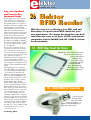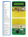
1
FREE RFID SEPTEMBER 2006 £3.80 www.elektor-electronics.co.uk R38 ™xHRKCQIy451 28zv!:^ Fo 410+ p r a FREE cop y a (‘It’s a ge catalogue of our cracke fr om Au r') www.ja ycarele log on to our stralia ctronic websit All pric s.co.uk/catalo e es £ Stg gue Starship Enterprise Door Sound Simulator KC-5423 £11.75 + post & packing This easy to build kit emulates the unique noise made when the cabin doors on the Starship Enterprise open and close. The 'shut' noise is also duplicated. The sound emulator can be triggered by switch contacts (normally open), which means you can use a reed magnet switch, IR beam or PIR detector. Kit includes a machined silkscreened, and pre-drilled case, speaker and all electronics components with clear English instructions. • Requires 9-12VDC power Two-Way SPDIF/Toslink Digital Audio Converter Kit KC-5425 £7.25 + post and packing This kit converts coaxial digital audio signals into optical or vice-versa. Use this bit stream converter in situations where one piece of equipment has an optical audio input and the other a coaxial digital output. Kit includes Toslink optical modules, PCB with overlay, case with screen printed lid, all electronic components and clear English instructions. Requires 9-12VDC wall adaptor (Maplin #JC91Y £14.99) For all you Trekkie fans POST AND PACKING CHARGES: Cost Order Value Cost Order Value £200 - £499.99 £30 £20 - £49.99 £5 £40 £50 - £99.99 £10 £500+ £100 - £199.99 £20 Max weight 12lb (5kg). Heavier parcels POA. Minimum order £20. Theremin Synthesiser Kit KC-5295 £14.75 + post and packing The Theremin is a musical instrument that was invented last century. By moving your hand between the antenna and the metal plate, you create strange sound effects. Kit includes a machined, silkscreened and pre-drilled case, circuit board, all electronics components and clear English instructions. As used in the Beach Boys classic hit ‘Good Vibrations’ Requires 9VDC wall adaptor (Maplin #GSR74R £9.99) High Performance Electronic Projects for Cars Book We stock an extensive range of quality automotive kits BS-5080 £7.00 + post & packing Battery Zapper MkII KC-5427 £29.00 + post & packing This kit attacks a common cause of failure in wet lead acid cell batteries: sulphation. The circuit produces short bursts of high level energy to reverse the damaging sulphation effect. This improved unit features a battery health checker with LED indicator, new circuit protection against badly sulphated batteries, test points for a DMM and connection for a battery charger. Kit includes case with screen printed lid, PCB with overlay, all electronic components and clear English instructions. Suitable for 6, 12 and 24V batteries • Powered by the battery itself Australia's leading electronics magazine Silicon Chip, has developed a range of projects for performance cars. There are 16 projects in total, ranging from devices for remapping fuel curves, to nitrous controllers. The book includes all instructions, components lists, colour pictures, and circuit layouts. There are also rojects p e s e chapters on engine management, advanced systems and DIY modifications. Over 150 pages! All All th 2VDC 1 ff o the projects are available in kit form, exclusively to Jaycar. Check out our website for all the details. work Hand Controller for Digital Adjusters Smart Fuel Mixture Display KC-5386 £25.95 + post & packing KC-5374 £8.95 + post & packing This hand controller is used for mapping/programming the independent electronic boost controller Kit (shown below). It features a two line LCD, and easy to use push buttons. It can be used to program the adjusters then removed, or left permanently connected to display the adjuster’s operation. It is designed as an interface and display, and is not required for general adjuster functions after they have been programmed. Kit supplied with silkscreened and machined case, PCB, LCD, and all electronic components. This kit features auto dimming for night driving, emergency lean-out alarm, better circuit protection, and a ‘dancing’ display which operates when the ECU is operating in closed loop. Kit supplied with PCB and all electronic components. • Car must be fitted with air flow and EGO sensors (standard on all EFI systems) for full functionality. Independent Electronic Boost Controller KC-5387 £25.95 + post & packing Superb control over your turbo boost curve. It can be used in cars fitted with factory electronic boost control using the factory control solenoid, or cars without electronic boost control using a solenoid from a wrecker etc. This is ideal for switching between say, a race/street mode, or a performance/wet weather mode. Boost curve selection is via a dashboard switch, and is all programmed using the handheld digital controller KC-5386 (shown above). Kit supplied with PCB, machined case, and all electronic components. • Suitable for EFI and engine management systems only Log on to www.jaycarelectronics.co.uk/catalogue for your FREE catalogue! 0800 032 7241 New 410+ page Catalogue (Monday - Friday 09.00 to 17.30 GMT + 10 hours only). For those who want to write: 100 Silverwater Rd All Silverwater NSW 2128 Sydney AUSTRALIA prices in PDS Recommended box UB3 (HB-6014) £1.40ea Picture shows Spray Controller fitted to the Display Kit. Add on Intercooler Water Spray Controller for Fuel Mixture Display Kit KC-5422 £3.00 + post & packing Simply add these few components to the Smart Fuel Mixture Display Kit (KC-5374) shown above and reduce water consumption by up to two-thirds. MikroElektronika MICROCONTROLLER DEVELOPMENT TOOLS Make PIC development easy with the EasyPIC3 Starter Pack - only £99! A development system designed to make developing and experimenting with PIC microcontrollers easy and ideally suited to beginners. • High quality development/experiment board with built-in USB 2.0 programmer and useful I/O devices. • Can be powered from your PC’s USB port or optional mains adapter. • Compatible with Windows 98/ME/NT4/2000/XP. • Supports virtually all 8, 14, 18, 28 and 40-pin PICmicro® devices in the 10F, 12F, 16F and 18F families. • Built-in I/O devices include switches, LEDs, seven-segment displays, potentiometers and RS-232 interface. • Connectors for character and graphic LCD modules, DS1820 temperature sensor, and USB and PS/2 interfaces. • All I/O lines available for off-board expansion. • Useful add-on boards available separately (see below). • BASIC, C and Pascal compilers available separately (see below). • Starter Pack includes PIC16F877A microcontroller, DS1820 temperature sensor, 16x2 character LCD, 128x64 pixel graphic LCD, RS-232 data cable, and USB programming cable for just £99. EasyPIC3 Add-on Boards - from £4.95 A range of add-on boards for use with the EasyPIC3 or in conjunction with your own designs. • DAC (12-bit D/A with SPI interface) - £9.95 • ADC (4-channel 12-bit A/D with SPI interface) £13.95 • ACCEL (2-axis accelerometer) - £11.95 • 485 (RS-485 interface) - £10.95 • CAN1 (CAN transceiver for CAN-enabled PICs) - £10.95 • CAN2 (CAN transceiver with SPI CAN controller) - £12.95 • KEYPAD (4x4 matrix keypad) - £4.95 • IRDA1 (IrDA transmitter/receiver) - £13.95 • IRDA2 (wireless RS-232 communications) - £13.95 • ETHERNET (SPI serial Ethernet controller) - available soon • RTC (battery-backed real-time clock) - £10.95 • CF (Compact Flash card reader) - £10.95 • MMC (MMC/SD card reader) - £10.95 • EEPROM (I2C EEPROM) - £4.95 mikroBASIC, mikroC and mikroPascal compilers - save 30% Three easy to use yet powerful compilers for PIC microcontrollers, ideal for beginners and experienced programmers alike. • Support for PIC12, PIC16 and PIC18 devices. • User-friendly integrated development environment (IDE), compatible with Windows 98/ME/NT4/2000/XP. • Highly adaptable code editor with useful features. • Useful tools include USART terminal, 7-segment display decode and ASCII chart. • Built-in routines support all EasyPIC3 I/O devices and add-on boards and include ADC, CAN, Compact Flash, EEPROM, Ethernet, Graphic LCD, I2C, LCD, 1-wire, PWM, RS-485, sound, SPI, USART, USB routines and many more. 30% discount for customers purchasing EasyPIC3. • • mikroBASIC - £85 (£59.50 with discount) • mikroC—£145 (£101.50 with discount) • mikroPascal - £85 (£59.50 with discount) Call 0845 226 9451 or order online at www.breadboarding.co.uk All prices exclude UK delivery (£5 normal/£10 next-day) and VAT. Major credit and debit cards accepted. Secure online ordering. 9/2006 - elektor electronics 3 e lektor lectronics leading the way Say, one hundred and twenty-five thousand cards Here at Elektor we’re never stuck for ideas, enthusiasm, inspiration and gusto when it comes to publishing a high quality magazine on electronics. And that’s despite the onslaught, in the UK newsstands, on specialist and trade magazines like ours in favour of publications carefully described as ‘having a wider appeal to the general public’. Fortunately, over the past few months sales of Elektor Electronics magazine have increased to the extent that we’re on the verge of re-entering the infamous ‘Top-1000’ of magazine titles sold through WH Smith — thank you all for your persistence in looking for our magazine! We get a lot of inspiration from you, our readers, but also from professionals in the industry we speak to from time to time (in various languages). To cut a long story short, the result of talking to just a few people (best described as being in the right place as well as fully aware of Elektor’s potential) is attached to this very copy of the magazine: a free RFID card containing a unique hexadecimal number string. Although RFID gets a lot of attention these days and the associated industry is used to handling really tall orders, our contact persons at Philips and ACG took a deep breath when told them we needed 125,000 cards to go with the full European print run of the magazine. After some more sighing and moaning from the printers, binders and the odd local distributor, everyone agreed that Elektor’s Giant RFID Card Quest went to prove that there may be some truth after all in the byline ‘leading the way’ we print with our masthead and logo. As far as I know, no other magazine has ever supplied free RFID cards in such great numbers as we’re about to do with this September 2006 issue. It’s a milestone and I’m sure the results of giving away a really useful item with the magazine will provide us with yet more inspiration and zest — they’re catalysts really in the publication process we run every month for you. Jan Buiting, Editor 26 Elektor RFID Reader With this issue we’re offering a free RFID card and description of a professional RFID reader for your own applications. The design described here can both read from and write to all types of RFID card that are compatible with the MIFARE and ISO 14443-A international standards. 14 RFID Chips Greet the Future RFID labels can be used to mark racing horses as well as containers, scooters and perfume packages. Passports and sportingevent tickets can also be fitted with RFID chips. The underlying technology is just as varied as the potential applications. 70 USB/DMX512 Converter Here is a project that will make some on the dance floors very happy... a DMX converter that will set you back just a few pounds. CONTENTS Volume 32 September 2006 no. 357 know-how Elekt Gian 40 Cubesats into Free Orbit t RFI or’s D read Card que st the c o d – e win – – hands-on a pri z e ! pag e 20 22 The Elektor Electronics RFID Card 26 Elektor RFID Reader 34 Experimental RFID Reader 46 DiSEqC Monitor 60 FPGA Course (4) 64 Electronic Stamping 70 USB/DMX512 Converter 76 Design Tips Miniature tweezers for SMDs Ready-built PCB available! technology 14 RFID Chips Greet the Future 52 E-blocks Easy ARM Pack 56 Upgrade for Flash Microcontroller Board 40 Cubesats into Free Orbit info & market 6 Colophon 8 Mailbox 10 News & New Products 81 Elektor SHOP 84 Sneak Preview The Delfi-C3 satellite designed by undergraduates offers its transponder and even asks amateurs to actively participate in its space mission. Taking your own pictures from space will soon be possible with the Compass-1, another amateur satellite. But can we shoot our own satellite into space? infotainment 20 RFID Card Quest 75 Retronics: Pontavi-Thomson Bridge 77 Hexadoku Subscriptions: Elektor Electronics (Publishing), Regus Brentford, 1000 Great West Road, Brentford TW8 9HH, England. Tel. (+44) (0) 208 261 4509, fax: (+44) (0) 208 261 4447 Internet: www.elektor-electronics.co.uk Email: [email protected] Rates and terms are given on the Subscription Order Form Volume 32, Number 357, September 2006 ISSN 0268/4519 Elektor Electronics aims at inspiring people to master electronics at any personal level by presenting construction projects and spotting developments in electronics and information technology. The magazine is available from newsagents, bookshops and electronics retail outlets, or on subscription. Elektor Electronics is published 11 times a year with a double issue for July & August. Under the name Elektor and Elektuur, the magazine is also published in French, German and Dutch. Together with franchised editions the magazine is on circulation in more than 50 countries. Editor: Jan Buiting ([email protected]) International editorial staff: Harry Baggen, Thijs Beckers, Ernst Krempelsauer, Jens Nickel, Guy Raedersdorf. Design staff: Ton Giesberts, Paul Goossens, Luc Lemmens, Karel Walraven Editorial secretariat: Hedwig Hennekens ([email protected]) The Netherlands Distribution: Seymour, 2 East Poultry Street, London EC1A, England Telephone:+44 (0)207 429 4073 Publishers: Elektor Electronics (Publishing), Regus Brentford, 1000 Great West Road, Brentford TW8 9HH, England. Tel. (+44) (0) 208 261 4509, fax: (+44) (0) 208 261 4447 www.elektor-electronics.co.uk. International Editor: Mat Heffels ([email protected]) Head Office: Segment b.v. P.O. Box 75 NL-6190-AB Beek Telephone: (+31) 46 4389444, Fax: (+31) 46 4370161 UK Advertising: Huson International Media, Cambridge House, Gogmore Lane, Chertsey, Surrey KT16 9AP, England. Telephone: +44 (0)1932 564999, Fax: +44 (0)1932 564998 Email: [email protected] Internet: www.husonmedia.com Advertising rates and terms available on request. International Advertising: Frank van de Raadt, address as Head Office Email: [email protected] Advertising rates and terms available on request. Copyright Notice The circuits described in this magazine are for domestic use only. All drawings, photographs, printed circuit board layouts, programmed integrated circuits, disks, CD-ROMs, software carriers and article texts published in our books and magazines (other than third-party advertisements) are copyright Segment. b.v. and may not be reproduced or transmitted in any form or by any means, including photocopying, scanning an recording, in whole or in part without prior written permission from the Publishers. Such written permission must also be obtained before any part of this publication is stored in a retrieval system of any nature. Patent protection may exist in respect of circuits, devices, components etc. described in this magazine. The Publisher does not accept responsibility for failing to identify such patent(s) or other protection. The submission of designs or articles implies permission to the Publishers to alter the text and design, and to use the contents in other Segment publications and activities. The Publishers cannot guarantee to return any material submitted to them. Graphic design / DTP: Ton Gulikers, Giel Dols Disclaimer Managing Director / Publisher: Paul Snakkers Prices and descriptions of publication-related items subject to change. Errors and omissions excluded. Marketing: Carlo van Nistelrooy Customer Services: Margriet Debeij ([email protected]) <RXUSULFHFRQVFLRXV3&%VXSSOLHU 2QOLQHSULFHFDOFXODWLRQ 2QOLQHRUGHULQJ 2QOLQHRUGHUWUDFNLQJ 2QOLQH+DQG' © Segment b.v. 2006 9HULILHG jODFDUWH ,QWHUHVWHG"&RQWDFWXV (PDLOHXUR#HXURFLUFXLWVFRP ZZZHXURFLUFXLWVFRP 6 2QGHPDQG Printed in the Netherlands SRROLQJIRUVWDQGDUGERDUGV XSWROD\HUV IURPWRSLHFHV IURPZRUNLQJGD\VRQZDUGV WHFKQRORJ\DWWKHULJKWSULFH XSWROD\HUV IURPWRSLHFHV IURPZRUNLQJGD\VRQZDUGV \RXUERDUGRXUFKDOOHQJH XSWROD\HUV IURPSLHFHRQZDUGV IURPZRUNLQJGD\VRQZDUGV elektor electronics - 9/2006 USB Oscilloscope & Logic Analyzer The new generation Scope for the age of microelectronics. 8 Channel 40MS/s Logic Analyzer Capture digital signals down to 25nS with arbitrary trigger patterns. 3 Input 100MHz Analog DSO Classic Analog Scope using a standard x1/x10 BNC probe. Additional inputs on the POD for dual channel operation. 8 + 1 Mixed Signal Scope True MSO to capture an analog waveform time-synchronized with an 8 channel logic pattern triggered from any source. Real-Time Spectrum Analyzer See the spectrum and waveform of analog signals simultaneously and in real-time Waveform Generator Load up to 32K arbitrary waveform and replay via the onboard DAC (10MS/s) or a digital pattern from the POD (40MS/s) Standard 1M/20pF BNC Input 200uV-20V/div with x10 probe S/W select AC/DC coupling S/W select 50ohm termination Arbitrary Waveform Generator Turn your PC or NoteBook into a powerful Scope and Logic Analyzer! See inside your circuit in the analog and digital domains at the same time to make tracking down those elusive real-time bugs much easier. Pocket Analyzer combines a high speed sample-synchronized storage scope and logic analyzer with a programmable waveform and logic pattern generator. Also included is an integrated real-time spectrum analyzer and powered "Smart POD" expansion interface so you've got all bases covered! About the same size and weight as a Pocket PC, this USB powered BitScope needs no bulky accessories. It's the perfect low cost "go anywhere" test and debug solution. BitScope "Smart POD" Connector 8 logic channels, 2 analog channels Dual channel capture from POD A/B Async serial I/O for external control Logic Pattern generator 32K 40MS/s BUS Powered USB 2.0 Device Single USB cable to your PC Compressed data transmission Simple ASCII control protocol BitScope Scripting Language External/Passthru Power Supply Auto senses an external supply removes power load from USB for use with unpowered hubs. Supplies up to 500mA via POD BitScope and your PC provide an array of Virtual Instruments • R&D • Education • Robotics • Lab Scope • Fast DAQ • Service • Debug BitScope Pocket Analyzer uses highly integrated Surface Mount technology to provide functionality you would expect from scopes many times the size and price. Its programmable Virtual Machine architecture means new functionality can be added via software. For custom Data Acquisition, export directly to your spreadsheet. BitScope DSO 1.2 software for Windows and Linux 9/2006 - elektor electronics www.bitscope.com 7 INFO & MARKET MAILBOX Brushless Motor Controller Dear Elektor people — I’m definitely interested in your brushless motor controller (February 2006) but have run into a few problems while studying the design in some detail. 1. In Figure 5 (control module schematic), the connection to +5 V on K3 (channel from/to transmitter) is missing. On the PCB this connection is present. 2. The pdf file supplied free of charge by the author mentions a ‘buzzer mode’. Also, it says that the configuration may be followed by means of ‘beeps’ from a ‘buzzer’ which I can no find anywhere in the design. How do I proceed? I would like to use this controller with a modified power stage in a model car that definitely requires active braking. The default settings mentioned in the pdf do not agree with those in the magazine… I gues the pdf and the controller are not too well matched. 214820 (by email) We confirm that the circuit diagram in Figure 5 fails to show that the centre pin of K3 is at +5 V, and that all +5 V points in the diagram are connected to this pin. The PCB however has all the right connections. This may be the cause of some confusion for which we apologise. The ‘buzzer’ in the pdf document is the motor itself, which will produce a buzzing sound when repeatedly reversed at a high 8 rate. Useful if your model car careers into the undergrowth! The default settings are best taken from the pdf document. We hope you will get your model car on the asphalt soon! article title can be supplied, any article since 1975 can be supplied as a photocopy and sent by post. We are however unable to find old articles based on vague or incorrect information. Old PCB numbers Dear Jan — while rummaging around on my loft I found an old Elektor printed circuit board numbered ‘EPS 9860’ I cannot remember anything about. The centre of the board has an LM324, two presets, diodes and a couple of electrolytics. Is this some kind of tone control or amplifier? FPGA, Colossus New & Old Dear Jan — I am reading your FPGA Course articles with interest. This is (coincidentally) in parallel with finding out more about the secret UK code breaking electronic computer of 1943 – ‘Colossus’ — which has been rebuilt and tectures. Do you or Mike Simpson know if anyone has been inclined to try? The 800-MHz Pentium emulator of Colossus runs slower than the valve and paper tape original, but it is of course a series emulation using software modulo-2 addition rather than using hard wired five bit parallel 0.5-MHz XOR adders like the original. It would be interesting to see how fast a 50-MHz FPGA emulator could run, though the subject is probably far too specialised to interest the general reader! Robert Cochrane (UK) Tanglung (Singapore) The EPS number 9860 is for a Peak Programme Meter from the January 1978 issue. The number may be confusing in this day and age because of the fist two digits ‘98’. In the old days (we’re talking about almost 30 years ago) a different PCB numbering system was used. Starting with the July/August 1978 double edition, a 5-digit PCB production number was adopted, for example, 78003, but only for Summer Circuits projects. The first two digits then indicate the year in which the project was first filed for publication. By November 1978 all articles got the 5-digit code, the first number issued being 79001. In January 1988 the system numbering was expanded to six digits, with the third digit (e.g., ‘4’) indicating a Summer Circuits article (e.g., 884056). From March 2000 on, any software and other article-related items followed this number system by means of an extension. Before this change, software items were consecutively numbered, independently of the article number. Elektor production number extensions -1 though -9 are reserved for PCBs; -11 through -19 for floppy disks and downloads; -41 through -49 for controllers and -91 through -99 for modules, kits and the like. A special Forum topic is available on our website to help readers find articles from Elektor issues published before 1995. Provided an EPS number and/or an exact Bill Tutte’s amazing statistical analysis of the German High Command Lorenz machine messages on which it was based. I have sent you a card showing the original (card reproduced here courtesy of Bletchly Park Trust Ltd, Ed.). I was intrigued by the links between the two (Colossus was a switch programmed gate array computer with an architecture based on the derived structure of the Lorenz machine wheels) and saw that Mike Simpson (‘Colossus Jr’, Elektor Electronics October 2005) is obviously very familiar with this work. I think it should be possible to build fast versions of Tunny (the electronic valve emulator of Lorenz) and Colossus with an FPGA, using a gate layout a bit like the original archi- Thank for the interesting email and the nice postcard Robert! I have copied your message to Paul Goossens, our in-house FPGA pundit and await his response to the challenge. £20 Sweex Router turned webserver Dear Jan — referring to the February 2006 Modding & Tweaking pages, I can now send strings from a web page to the second serial port and there is no “terminal chatter” to mess things up. See www.sunspot.co.uk/Projects/ SWEEX/second_rs232.html and www.sunspot.co.uk/Projects/ Sweex.htm elektor electronics - 9/2006 Corrections & Updates 2006 issue for a better appraisal of Jeroen’s “general approach” to electronics. I am trying to persuade the ‘Linux Gods’ to let hardware enthusiasts use their product as an ‘Embedded Linux Distro’ — one is working well enough to be of use and can be downloaded. They seem to modify Linux for its own sake — I want a tool to control hardware — hence my website. Please keep the Jeroen Domburg projects coming — but support a proper ‘distro’ tool for use of those of us who solder. The files on the USB stick can be modified without needing to change the router firmware from that published by Elektor. Your author Jeroen Domburg led me into a new world of embedded Linux — trouble is they are all experts out there and there is almost no basic tutorial for an absolute beginner like me. You should have printed a health warning ! But then I may not have jumped and I am glad I did. I only think a few of us did though. I would love to see such a tutorial in Elektor. At below £20 all in the Sweex etc. are fantastic platforms compared to the average micro board. Pay Jeroen to build an Embedded Linux “distro” that addresses all the ports and is easy to customise — available from your site(?) Graham (by email and on EE Forum) Glad to see that the article spurred you into learning a bit about embedded Linux, Graham. The monthly Modding & Tweaking pages supplied by Jeroen are currently among the most popular in our magazine. See also ‘Electroshack’ in the July August 9/2006 - elektor electronics ARMed for IDE, and more Dear Jan — In the April 2005 issue you asked for details of practical applications for the Elektor Electronics ARMee Development System. I use my board as a test bed for embedded code development and to test other hardware. I do a lot of long term tests logging the results over sever- al hours or days. To this end, I designed an IDE interface board inspired by a couple of similar designs in Elektor (see photo). I can connect one or more hard disks, a CDROM drive and a CF card. I wrote FAT and ISO filing system drivers — all in all a very useful little system. I designed it in a way that allows more than one card to be plugged into the expansion connector at the same time (using a simple parallel bus) so my setup actually consists of an ARMee board connected to a 4-slot backplane. Then each card plugs into the backplane. However, I haven’t yet got round to making any other types of boards, though I do have a paper design for an I/O card with A/D, D/A, relays, more digital I/O etc. I also thought of designing a completely new system with an ARM9 core on a board that plugs into the backplane. This would be a much more flexible, modular system which could be expanded FPGA Prototyping Board March 2006, ref. 050370-1 A small number of FPGA Prototyping Boards from the first production batch have six SMD electrolytic capacitors fitted the wrong way around: C5, C6, C7, C13, C14 and C15. The dash on these capacitors has to be at the side of the connectors. If they are at the side of the LCD, there are two options: 1. you remove the capacitors and refit them with the correct orientation; 2. you return the FPGA board to us and we will do the above free of charge. In any case, do not apply the supply voltage before it has been ascertained that the six electrolytics are fitted the right way around. easily. Just a thought. Please can you pass this info on to the designer. from my cells but one colleague was only getting 70% or so and blamed his cells. A quick swap of cells and charging on my charger produced in excess of 95%. The result is that this tester is a good way of checking that your charger is doing what it is required to do. It is pointless getting higher and higher capacity cells if your charger is not fully charging them. Geoff Moore (UK) Dave (UK) Good to see Dave that our articles, boards and software have enabled you to actually build such an impressive system. This sort of information is very rewarding not only for the respective authors but also for us editors and designers working in a publishing company. The article produced a good response and other readers have informed that it has enabled them to once and for all sort out ongoing problems in the ‘battery department’. MailBox Terms – Publication of reader’s correspondence is at the discretion of the Editor. AA cells fully charged? Dear Editor — several of my colleagues and myself have built this useful piece of equipment (Simple Rechargeable AA Cell Characteriser, April 2006, Ed.) and have found that not only does it check the quality of an AA cell but it also checks the amount of charge that different chargers put into the cells. I get between 98% and 103% of the rated capacity – Viewpoints expressed by correspondents are not necessarily those of the Editor or Publisher. – Correspondence may be translated or edited for length, clarity and style. – When replying to Mailbox correspondence, please quote Issue number. – Please send your MailBox correspondence to: [email protected] or Elektor Electronics, The Editor, 1000 Great West Road, Brentford TW8 9HH, England. INFO & MARKET NEWS & NEW PRODUCTS Compact varifocal camera deView has launched its new Varifocal Day/Night IR Bullet camera to meet the demand for high performance compact cameras. Claimed an excellent choice for active monitoring and surveillance programs, the varifocal Sony 1/3-inch CCD compact camera features built in infra-red LED with automatic backlight compensation. The 480 TV line colour camera is equipped to operate in various light conditions, automatically switching from colour images to high sensitivity monochrome-mode in low light environments. Designed for discreet surveillance and easy installation, the bullet camera has an attractive aluminium weatherproof housing together with slide-on sun shield and optional adjustable mounting bracket. This aesthetically pleasing product can be installed internally and externally. Ideal for industrial and domestic property, commercial buildings and public buildings such as hospitals, schools, airports, ports etc. www.deview.com. (067111-10) New generation Dataman universal USB programmers Dataman has launched a new range of truly universal programmers built to meet the demands to support all device technologies. The new programmers all have a USB2 interface, which will particularly suit the needs of those engineers who prefer to use a laptop for program development. The Dataman-40Pro is a small, fast and portable programmer with a 40 pin socket designed to support a wide range of memory and logic devices, including the latest low voltage chips. It is ideal for the engineer on-the-move who needs to set up his working environment quickly in a small space. The Dataman-48Pro is for engineers who want the best programming speeds and need to cover the widest possible range of memory and logic parts. It supports over 25,000 devices, from 5 volts down to 1.5 volts. The Dataman-40Pro and Dataman-48Pro both have an In System Programming (ISP) connector with a JTAG interface, which programs chips whilst still inside the end target system. Large quantities of chips can be programmed more quickly by connecting multiple 48Pro programmers to the same PC. This setup will work either as a gang programmer or to program chips with different data simultaneously. The Dataman-448Pro is built to meet the demands of high volume production programming with minimal operator effort. The Dataman-448Pro features four independent universal programming modules with support for over 22,000 devices. The new programmers are operated from an easy to use Windows interface. Software to cover new chips is released every 2-3 weeks and may be freely downloaded from Dataman’s website. To show their confidence in these new products Dataman is covering them for a 3 year warranty period. (067192-1 www.dataman.com New searchable listing of European technology events Tech Event Guide Ltd announces a new searchable online database which aims to become the definitive free listing of technology events throughout Europe. Unlike other listings, the online Tech Event Guide (www.techeventguide.com) includes information on key industry shows and conferences as well as company-specific seminars and training days provided by manufacturers and distributors. Registration to the site is free and 10 electronics engineers can browse a continually updated list of events by date, name or location, or make a selective search for events by location and key products areas such as Analogue, RF and Microwave, FPGAs, ASICs, & Logic, Power and Power Supplies, Processors, Microcontrollers and DSC or industry sectors such as Automotive & Transport, Aerospace and Defence, Communications & Networking, Control & Automation or EDA/Design Tools. elektor electronics - 9/2006 Users can download registration forms and event literature directly from the Tech Event Guide website or to click a link through to the event’s own website for additional information. Once registered, users can create their own ‘My Tech Event Guide’ profile so that they can monitor every opportunity to improve their skills and industry knowledge within their chosen locations, product groups and industry sectors. Companies can add details of their own seminars and training days to the site by completing the free registration and uploading their event information either as a free listing or as an enhanced listing. Mike Maynard, Director of Tech Event Guide explained, “Although Event Diaries are already available, they typically focus primarily on major events and rarely include company-specific events. By giving registered companies the ability to upload details of their own seminars and training days, the database aims to build into a definitive listing of technology events, and a valuable resource for electronics engineers, in every country throughout Europe.” (067192-3) www.techeventguide.com Network cable analyser gets an intelligence boost Peak Electronic Design Limited have launched an enhanced version of their Network Cable Analyser the Atlas IT (model UTP05), designed and made in the UK. The Atlas IT has always had the unique ability to analyse many types of RJ45 based network cabling, including Ethernet, Token Ring, Patch cables and Crossover Cables. The connection pattern of the cables is automatically recognised and displayed on the unit’s display as well as confirmation of the full connection pattern. Now the Atlas IT has been enhanced with cable defintions of 8 more cable types, including Cisco terminal cables, Linn Audio network cables, Ethernet Economisers, 4 line crossovers, voice/data cables and many more. Additionally, for the first time ever, the Atlas IT can now recognise the cable type even if there are connection faults (such as missing connections, swapped lines or other errors). It will display the cable type and highlight any lines that have errors. The Atlas IT hardware has had a boost too, now it can cope with connection to live comms systems and even withstand the high telephone ring voltages (upto 80 V) associated with mixed voice and data cabling. Using the Atlas IT could not be easier, connect the main unit at one end of your cable run and the miniature (18mm cube) terminator at the other end. For socket testing you can use the supplied mini patch leads too. Press the test button and after a few seconds the results of the analysis are displayed on the clear alphanumeric display. If you use the unique Identified Terminators, the Atlas IT will identify the cable run for you too, allowing the easy testing and identification of many cable runs (upto 24) without having to make lots of trips to swap terminators. The Atlas IT will automatically power down after a period of inactivity, so you’ll never forget to switch it off. Measuring just 103mm x 70mm x 20mm, the Atlas IT fits in the palm of your hand or could even happily dangle from a network socket! When it’s not in use, it can be stored safe and sound in the supplied custom machined carry case along with your accessories, terminators, cables and a spare battery. The Atlas IT is available from many distributors including Farnell and Maplin as well as directly from the manufacturer for £89.00 fully inclusive of UK delivery and VAT. (067192-2) Peak Electronic Design Limited, Atlas House, Harpur Hill Business Park, Buxton, Derbyshire SK17 9JL. Tel. 01298 70012, Fax. 01298 70046. email: [email protected] web: www.peakelec.co.uk Single-chip GPS receiver with highest sensitivity and low power consumption Atmel® Corporation and u-blox AG, recently announced the availability of their latest weaksignal tracking GPS technology in an ultra-small form factor. The new single-chip ATR0635 measures just 7 x 10 mm, and integrates a complete ANTARIS® 4 GPS receiver including ROMbased SuperSense® software in a 96-pin BGA package. The small size plus the extremely low power consumption (62 mW in continuous power mode) make 9/2006 - elektor electronics the ROM-based ATR0635 an excellent fit for handheld and mobile applications such as mobile phones, PDAs, smartphones, after-market navigational products, and recreational consumer products. Other products such as GPS ‘plug-in’ accessories for PCs, small GPS mice, Bluetooth® GPS devices, and other accessories equipped with GPS functionality will also enjoy the single chip’s advantages in terms of small size, reduced power needs, and built-in features such as the ANTARIS 4 USB port. Its high tracking sensitivity of -158 dBm allows for weak-signal tracking in urban canyons and even indoors. The 96-pin, ball-grid-array single chip has an excellent cost-performance ratio due to needing only a few external components. The ATR0635 also brings benefits such as simplified chipset integration which accelerates design projects for ANTARIS 4- based products. ATR0635 samples in 7 x 10-mm 96-pin BGA packages are available now. Atmel and u-blox offer a complete evaluation kit including ultra-small footprint example design which helps to dramatically shorten development cycle times. Further information may be found at www.u-blox.com/products/ atr0635.html . (067192-5) 11 ByVac Electronics Cool Blue 16x2 LCD illuminated white lettering can be seen in full daylight. Makes projects stand out from the rest £9.95 Cool Blue 16x2 LCD fitted with the serial interface, simple text commands can scroll display, turn back light on off etc. Very powerful. £22.90 Serial LCD controller, will control any HD44780 compatible displays, 1,2 or 4 lines up to 180 total characters, fully software configurable automatic Baud rate etc. Works from RS232 port, USB to serial converter or directly from a microcontroller. Simple two character text commands for full control. Very small will fit behind the display. Scrolling text, macro facility, and much Only 40mm x 19mm ! more. £11.00 Serial Analogue board, 10 bit, 3 analogue inputs, 2 digital I/O, all serially controlled using simple 2 letter text commands. Analogue as percentage or absolute 10 bit value. £12.50 General purpose Digital-Analogue input/output. Converts serial text commands into digital I/O, 4 digital I/O and 4 analogue input channels. £11.00 Control hardware using simple text commands see www.byvac.co.uk RS232 Serial Lead £4.50 Power Regulator £4.95 MONEY BACK GUARANTEE If you are not completely satisfied, return the goods within 30 days for a full refund. Purchase Options: On-Line at www.byvac.co.uk • Telephone 07905 734 348 • email [email protected] • Cheque or Postal Order to: ByVac, PO BOX 4049, Penistone, SHEFFIELD, S36 6WP Post and packing UK £2.50 World Wide £3.50 10% discount code for online orders use ELK6 The World Beating PCB design software Easy-PC version 10 sets another milestone Winning accolades the world over, Easy-PC for Windows V10 is another major milestone in the evolution of this extremely popular software tool. Try a demonstration copy of Easy-PC and prepare to be amazed at the power, versatility and remarkable value for money. Version 10 features LL £24 FRO MO PLU S VA T NLY 7 Fully integrated Schematics & PCB layout in a single application complete with forward and back annotation. Design and rules checks at all stages ensure integrity at all times. Professional manufacturing outputs allow you to finish the design process with ease. Intelligent Gerber Import option Stop press... Stop press... Stop press... Stop Track/Shape ‘Hug’ Mode Routing Easy-PC imports Eagle files as well as Tsien Boardmaker Text Callouts Layer & Via Stack Previews Blind & Buried Via Support call for a brochure, prices & CD on +44 (0)1684 773662 Teardrop Pads or e-mail [email protected] Draw Spacing Clearances you can also download a demo from Spiral Tracks & Shapes Plus many more exciting features...... Oak Lane, Bredon,Tewkesbury, Glos. GL20 7LR. United Kingdom www.numberone.com 12 STI press... 2 files 25 YEARS 1979 - 2004 elektor electronics - 9/2006 TECHNOLOGY RFID RFID Chips Greet t Renke Bienert RFID labels can be used to mark racing horses as well as containers, scooters and perfume packages. Passports and sporting-event tickets can also be fitted with RFID chips. The underlying technology is just as varied as the potential applications. An employee of the Metro trading firm pulls a pallet of diapers through an RFID reader gate, which rapidly reads the data from the chips. The antennas of the RFID reader are located to the left and right (visible on the right side). (photos: Philips) Inanimate objects, as well as animals and in principle people, can be identified automatically without direct contact if they are fitted with small radio-frequency identification (RFID) responders. This technology is poised for a breakthrough this year in many sectors. In the near future, RFID labels will be so cheap that they can be used to mark even relatively low-priced goods. The route taken by every milk jug, aspirin package or newspaper from production to selling (and possibly even further) could then be tracked electronically. Logistics specialists welcome the new technology because it promises to yield considerable cost and time savings in transport and storage, but many consumer associations and more than a few champions of privacy are worried about the potential for ‘transparent customers’. Curse or blessing? The mood among the general public is equally contradictory, as was already shown by our brief international RFID survey on the Elektor Electronics website. For instance, 80% of the participating readers assumed that RFID tags will make their everyday lives easier, but an equally large percentage thought that personal privacy and data protection are ‘threatened’. Perhaps the high level of insecurity arises from the fact that radio-based identification cannot be seen or heard, just like ‘electrosmog’. The possibility that an RFID responder that you 14 may be carrying, whether or not you are aware of it, could be read out by a government authority, a company or an avid hacker is thus a fear that must be confronted by the manufacturers of this technology. This fear is also fed by horror stories, such as the story that a security company ordered its employees to have RFID chips implanted under their skin. However, as with nearly all innovations the entire technology should not be condemned based on a few particular applications. Besides that, there is certainly more than one form of RFID. Consequently, the simultaneous appearance of media reports on RFID viruses and 2006 World Cup tickets or passports fitted with RFID chips does not necessarily mean malicious programs will spread via your passport or admission ticket that in the future (see also the web links at the end of this article). RFID in a nutshell First, a brief explanation of the terminology: the ‘RF’ in ‘RFID’ stands for using radio frequencies to transmit data and possibly also energy. The term ‘ID’ can refer to a variety of applications, ranging from simply reading numbers to encrypted data exchange or complicated computations for verifying the authenticity of an identification document. A RFID system normally consists of a transceiver (or ‘reader’) and a number of RFID responders, which are sometimes called ‘tags’, ‘transponders’ (a elektor electronics - 9/2006 the Future wrong use of the term) or simply ‘cards’. It’s also necessary to make a distinction between active and passive responders. Active responders are powered by batteries, while passive responders take their operating power from the field emitted by the transceiver. Here we limit our attention to passive responders, because they are smaller and cheaper than active responders and thus far more significant for everyday applications. A brief overview of RFID devices data rate of a few kilobits per second. The tag usually holds only a number that can be linked to product characteristics in a database. In many cases, the database can be accessed via the Internet, which means it can be consulted from Beijing just as easily as from San Francisco. The new Electronic Product Code (EPC) standard Coupling methods Three different types of coupling can be used for data transmission between the responder and the reader: capacitive, inductive, and electromagnetic, with the latter being important at relatively high frequencies. Capacitive coupling employs the electrical field and is limited to a small transfer range. It is thus rather insignificant in practice. Inductive coupling uses a magnetic field to transfer energy and data, with a coil being used as an antenna (Figure 1). Systems operating at 125 or 135 kHz, as well as at 13.56 MHz, are in widespread use. The choice of these specific frequencies has nothing to do with the technology, but is instead based on legislation that makes these frequencies available for RFID applications. Applications using inductive coupling are already quite common. At high frequencies such as 434 MHz, 862–956 MHz and 2.45 GHz, the coupling is no longer purely inductive or capacitive because the wavelength is small relative to the size of the components. In this case, propagation of electromagnetic fields through space is used to transmit energy and data. Tagging A basic distinction is made between ‘object-related’ and ‘personal’ applications. In the former case, the responder takes the form of a label attached to an object (see Figures 2 and 3). Such responders attached to goods are often called RFID tags or RFID labels. Logistics specialists may want to know when an object is at a certain location. Using RFID tags, data for all delivered pallets and cartons can be acquired automatically when the goods are delivered. That makes it easier to keep track of inventory, helps reduce shrinkage due to theft, and facilitates distinguishing genuine goods from counterfeits. The largest possible reading range and easy operation are important factors in such applications. They do not require complex computational operations in the RFID tags or large data volumes, but they do require large numbers of tags to be read quasi-concurrently. Reading several hundred or even a thousand tags per second at a range of tens of centimetres to a few metres (extending to more than 5 m) is readily possible. That is offset by small data volumes (several bytes) and a 9/2006 - elektor electronics Figure 1. RFID label with antenna and chip. Figure 2. Label inlays on a roll. An inlay consists of a chip, an antenna coil and a substrate (paper or film). Figure 3. Manufacturing RFID labels. If you look closely at the bottom surface behind the roll, you can see the antenna coils shining through the base layer. 15 TECHNOLOGY RFID Frequencies for RFID tags 100 – 150 kHz 13.56 MHz UHF 2.45 GHz Influence of water and humidity Low Low High Very high Influence of metals Low High High* High* Responder design Simple Simple Complex Very complex Range Short Medium Large Large Number of readable responders Small Large Large Large * This can be minimised with a suitable tag design. Contactless interface as specified by ISO/IEC 14443 energy provided by the reader is sufficient to operate a microcontroller. As it is basically impossible to say in advance whether more than one card is within the operating range of the reader, card selection must occur before the actual communication session in order to ensure that only one card is addressed (collision protection). Analogue portion Mifare technology uses a contactless interface that complies with the ISO/IEC 14443 standard. A carrier frequency of 13.56 MHz is used for energy transfer and data transfer between the reader and the card. The read/write range is limited to a distance of less than 10 cm. As shown in the illustration, the contactless interface can be explained in simplified terms using the operating principle of a transformer. The antenna coil of the reader generates an alternating magnetic field at 13.56 MHz. In simplified terms, the reader antenna can be regarded as the primary winding of a loosely coupled transformer. The card antenna acts as a secondary winding that picks up part of the generated magnetic field. This provides the card chip with the necessary energy. (The terms ‘PCD’ and ‘PICC’ used in the figure come from the ISO standard and are explained in the glossary.) The magnetic field is amplitude modulated by the reader to transfer data from the reader to the card, in this case using a Miller-coded data stream and binary 100% modulation in accordance with ISO/IEC 14443A. Load modulation is used to transfer data in the opposite direction (from the card back to the reader). This means the card uses the modulating data signal to switch a load in or out. The variations in the load on the ‘secondary’ side of the transformer are detected by the reader on the ‘primary’ side. The data rate is 106 kbit/s in both directions (optionally as high as 847.5 kbit/s). The 16 Digital portion Data (including user data) can be transferred after the card has been selected. The following rules apply: • ‘Reader talks first’: the transceiver always transmits first and the card replies. • The card always replies within an agreed time, while the transceiver can take its time. In the simplest case (as with the Mifare Ultralight card used in our RFID reader project), this is accomplished by direct use of suitable card commands (‘Read’ and ‘Write’ in the case of the Mifare Ultralight card). This means there is only a simple, rigid protocol, and errors cause termination of the communication session. This is naturally impractical for relatively complex applications, so there is also a flexible transmission protocol for microcontroller smart cards. It is specified in Part 4 of the ISO/IEC 14443 standard. This protocol: • allows different sizes of data blocks (depending on the buffer size of the card or reader) • defines an error handling procedure (error detection and correction) • permits chaining of data blocks to transfer relatively large data volumes • supports flexible timing (which means the card can request extra time for execution of a command) elektor electronics - 9/2006 guarantees internationally unique product numbers, which represent a sort of electronic barcode. Smart cards ‘Personal’ responders impose different technical requirements. In this case the responders are generally referred to as ‘smart cards’ instead of ‘tags’. With a smart card, the user must always actively initiate a read/write process by bringing the card close to a transceiver. A large operating range is not only unnecessary in this case, it is also undesirable. Unauthorised reading of the data can be prevented by design by keeping the operating range as small as possible. The standardized interface for contactless smart cards (ISO/IEC 14443) thus defines the technical parameters such that the maximum possible range is limited to 10 cm (see inset). However, it may be necessary to exchange relatively large amounts of data in this case (up to several kilobytes), and suitable data security is naturally required as well. The contactless interface is designed to supply energy to suitable microcontrollers embedded in smart cards and transfer relative large data volumes at rates up to several hundred kilobits per second. Sample applications include the new electronic passport (see the web links) and electronic tickets for local public transport systems, like Oyster on the London Underground. Which frequency for what? Contactless smart cards generally operate at 13.56 MHz and typically employ the ISO/IEC 14443 standard (see inset). The Mifare technology described in the RFID reader project in this issue is the most widely used technology worldwide for smart card RFID applications. Selecting the right frequency is more complicated for tagging applications. As indicated in the table, various factors come into play at different frequencies. The influence of water is negligible at very low frequencies, but it increases at high frequencies. As water absorbs a lot of energy at 2.45 GHz, for example, it is better to choose 135 kHz for systems that must work under conditions of high relative humidity. In a metallic environment, such as with an RFID tag on a beer keg, it is better to select a low frequency or design a UHF tag with a suitable antenna. Antenna design for tags that use inductive coupling is easier than for high-frequency tags. On the other hand, UHF tags have a larger theoretical range, which is essentially limited only by statutory provisions. Naturally, the number of tags that can be read per second is higher at relatively high frequencies due to the greater available bandwidth. Security System security and data security must be given adequate attention before the system is put into service. Of course, the requirements depend on the specific application. In a system with object-related RFID tags, which in the simplest case only replace barcode labels, it is basically not necessary to have any more security than when barcodes are used (but also no less!). The data is stored in compliance with a standard and can be write-protected. However, everyone who has access to the tag can read and copy the stored data, just as with a barcode. In contrast to barcode systems, it is relatively easy to increase the functionality and security of RFID tags. The first step is to protect the data against copying. One way 9/2006 - elektor electronics Preventing replay A typical application for contactless smart cards is an access control system, such as for a company. Every employee with access authorisation carries a badge containing a smart card. The employee holds the card in front of a reader before entering a secure area. That causes access to be granted or the door to open automatically. Of course, the authorisation data is transmitted between the card and the reader in encrypted form. However, a ‘session key’ is needed to prevent an attacker from recording the transmitted data and then simply using it again (a ‘replay attack’). In the ‘3-pass mutual authorisation’ method, the correctness of the secret key is verified and a session key is generated. This works as follows: 1) The card generates a random number RndB, which is encrypted using a secret key and then sent to the reader. 2) Decryption in the reader then yields the same random number RndB if the reader uses the same secret key. The decrypted number is permutated to form the number RndB*. The two numbers RndB* and RndA are then encrypted and sent back to the card. 3) The card recovers the two received random numbers by decryption and reverses the permutation of RndB*. If the result is the same as the number RndB previously generated by the card, the keys used by the card and the reader must be the same. In this way, the card recognises that the reader is authentic. The card then permutes RndA to generate RndA*, encrypts RndA*, and sends this number back to the reader. 4) Now the reader can decrypt RndA* and convert it back to RndA to test the correctness of the key that was used. If the test is successful, the reader has recognised that the card is genuine. After this authentication both sides know that they are using the same key, even though the key never left the card or the reader. A temporary session key can now be generated from the random numbers, which are known only to the reader and the card because they were transmitted in encrypted form. The session key is then used for data encryption during the rest of the communication session. The advantage of such a session key is that it is based on random numbers, which means a new key is used in each session. That effectively defends against replay attacks. to do this is to assign each RFID tag a unique identification number (UID). The UID is stored in unalterable form in the memory of the RFID by the chip manufacturer and thus provides a basic form of protection against copying. Secret keys The next step is to us this method to protect writeable (or rewriteable) memory areas against misuse. Here the UID Web links RFID card applications everywhere in the world: www.mifare.net/news/#press World Cup ticket with RFID chips: www.elektor-electronics.co.uk/Default.aspx?tabid=27&art=53048&PN=On Technical details of electronic passports: www.elektor-electronics.co.uk/Default.aspx?tabid=27&art=53049&PN=On RFID viruses: www.elektor-electronics.co.uk/Default.aspx?tabid=27&art=53050&PN=On Explanation of DES and Triple DES: en.wikipedia.org/wiki/Triple_DES 17 TECHNOLOGY RFID nically possible, complex methods are usually not used in simple systems for cost reasons. Data safe Figure 4. The advantages of RFID technology come to the fore with perishable goods, since it saves time in transport. is used to generate a chip-specific secret key that is used to encrypt the data. The user requires the following to evaluate the data stored in such a tag: • the UID • a secret key • knowledge of the encryption method that is used Other ways to protect data include password functions and true encryption processes in the tag to encrypt the transmitted data as well. Although many things are tech- Smart cards typically require a relatively high level of security because personal data (such as with a passport) or relatively large monetary values (such as with an electronic ticket) are often stored in them. The same security requirements can fundamentally be fulfilled with contactless smart cards as with contact cards. Naturally, the first step is to encrypt the transmitted data. There are various standards for this purpose, with the degree of security typically being stated in the form of the length of the key. In simplified terms, the length of the key corresponds to the statistical number of incorrect attempts to guess an unknown key. In the case of a DES algorithm with an 8-byte key, of which only 56 bits are actually used for the key, the single correct key must be found from among 72,000,000 billion possible keys. This sounds like a very large number, but in an era of networked computers there are many applications for which it does not provide adequate security. One option is to use a longer key, such as 112 bits with Triple DES, or a different encryption method. Here again, effort and cost must be weighed against the required security, and for that reason many different concepts are available. However, the security of a system consisting of several components is only as good as the security of the weakest link in the system. There is thus little point in encrypting the data in the card if it is possible to eavesdrop on a communication session and then simulate a new session. However, effective methods for protecting against this form of attack and several other forms of attack are available (see the ‘Replay’ inset). (060204-1) RFID glossary Tagging Capturing tags (including RFID tags) ISO International Organization for Standardization IEC ISO/IEC 14443 PCD 18 UHF Ultra High Frequency; in this case frequencies in the 862–956 kHz band International Electrotechnical Commission Eavesdropping Undesirable listening in on RFID communications International standard for a contactless smart card interface with a maximum range of 10 cm and an operating frequency of 13.56 MHz Skimming Undesirable use of an RFID label or contactless smart card Replay attack An unauthorised transaction generated by repeating a previous transmission obtained by eavesdropping Proximity Coupling Device: a transceiver for contactless smart cards (complaint with ISO/IEC 14443) PICC Proximity Chip Card: a contactless smart card (complaint with ISO/IEC 14443) ISO/IEC 15693 International standard for a contactless label interface with a maximum range of 1.5 m at 13.56 MHz ISO/IEC 18000-6 International standard for a contactless label interface with a maximum range of 3–7 m, operating in the UHF band and/or at 2.45 GHz Modified Miller coding Pulse position coding scheme in which specific pulses are omitted to save energy DES Data Encryption Standard: a symmetric encryption method for 8-byte data blocks with a key length of 56 bits (8 bytes without parity bits). See the web links. 3-DES, Triple DES A standardized encryption method consisting of three DES loops for increased security, with a key length of 112 bits or 168 bits (see web links) elektor electronics - 9/2006 Lichfield Electronics The Corn Exchange, Conduit St, Lichfield. Staffs. WS13 6JU Tel: 01543 256684 E-Mail: [email protected] LED Flashing Kits Arrow Chasing Light 21 LED Telephone kits Build Your Own Telephone Switch and control kits Infrared Remote Relay A simple but fun kit to build an LED pointing Arrow, ideal for near exits or as an indicator? 2.9”x2.2”, 9-12V This great kit lets you build a tone/pulse phone With mic and ear piece, no batteries required. A great kit to build and use. Control 1 10A Mains device by infrared Remote control. Range: 25ft. (on/off) 2ch 50ft version also available 6 program 4 channel DC chasing light. 12V 100W. (FK144) £15.99 Electronic Windmill 25 LED ,adjustable speed. (FK153) £9.99 4 way traffic light. 12 LED. How do they work? (FK148) £9.99 Two Way Chasing Light 35 dot. Uses LED display. (FK151) £7.99 240V flasher. 2CH 1400W, adjustable speed. (FK144) £7.99 Two way V.U. Meter. 10 LED. Displays volume (FK102) £4.99 Telephone In Use indicator. Requires phone lead (FK318) £2.99 Telephone Interceptor: Listen in on phone calls. (FK306) £8.99 Telephone Radio Transmitter (FM 88-108 Mhz) (FK320) £8.99 10W Telephone Ringer, drives bell or speaker not inc(FK305)£9.99 Phone Ring Signal 500W Flash a lamp when the phone rings£12.99 Dual Station Intercom with speakers (FK313) £10.99 £9.99 Postage Order Value P&P Cost £4.99-12.99 £2.00 £13.00-22.99 £3.00 £23.00-49.99 £8.00 £50-£150 £10.00 Above prices UK Only. Phone or e-mail for Ireland . Payment by cheque, card or P/O 133 Kits in stock!!! £18.99 £28.99 Light Dimmer 500W: uses a Triac. With LED (FK415) £5.99 Light Sensor with 5A 250V relay. With LED (21-053) £6.99 Touch Switch 10A 240V Touch on/touch off (FK405) £8.99 Voice control switch 7A 240V, clap on/clap off (FK409) £9.99 Water Pump Level Control with 7A 240V relay. (FK425) £9.99 Electronic Code Switch & relay. 7A 240V 4 digit. (FK422) £14.99 Power Supply kits 0-30V 3A Variable Regulator Power Amplifier Kits 15+15W Power Amp Build a high quality variable voltage regulator Using this simple to assemble kit. 30VDC or 2x12VAC required This quality kit uses 2X TDA200SR IC’s, Includes heat syncs and full instructions. Requires only a 12V power source. (FK608) Power Amp. OTL. 30W Mono R1%: Req 50VDC (FK656) £14.99 Power Amp. BTL. 15W Mono. Req 12VDC (FK607) £14.99 Power Amp. IC 8+8W Stereo. 12VDC TDA200SR (FK605) £13.99 Power Amp. IC 8W Mono. 12VDC TDA2030 (FK604) £8.99 Power Amp. 2+2W Stereo 3-12V DC TBA820M (FK603) £9.99 Power Amp 2W Mono 3-12V DC TBA820M (FK602) £5.99 £15.99 0-30V 1A Variable Regulator, as above but 1A. (FK808) £7.99 Variable DC Regulator 0-12V from 12V. 500mA. (FK807) £4.99 DC Down Converter. 12v to 6 or 9V. Uses 7806 (FK805) £3.99 Power Supply 6-9-12V 0.3A. Inc transformer (FK801) £8.99 Mini Emergency Light. When mains fails, it lights(FK802) £5.99 12V Low battery alarm. Suit car or boat. (FK915) £6.99 £24.99 Intruder Alarms Magnetic Switch Alarm Radio kits Shortwave Radio Reciever Make a digital burglar alarm with this great Kit, simply attach the magnet to a door and the switch to the surround, hide the control board, arm it and wait. A great kit to make a short wave reciever for 2.2 - 7Mhz. Easy to build. Uses the 4007 IC. 9V (21-020) £16.99 Passive Infrared Sensor & relay 5A 250V delay off (FK510) £27.99 Infrared Burglar Alarm/relay. Make an IR tripwire. (FK505)£24.99 Intruder Alarm with delay function & speaker. (FK501) £9.99 Visitor Chime with speaker. Ding Dong. Req switch (FK502) £7.99 £9.99 Walky Talky Kit, pair. 27Mhz. 150mW to 1W (FK711) £34.99 Advanced AM/FM Radio & case. Req Freq Gen (21-027A)£16.99 Simple FM Radio 88-108Mhz. Uses TDA7000 (FK707) £14.99 Advanced AM Radio & case. Req freq generator (21-028A) £13.99 FM Wireless Mic: Very simple transmitter. 9V (FK702) £6.99 Pocket Transistor Radio: Uses MK484 clone IC (21-001) £9.99 Our Shop Located in the city centre of Lichfield We are within easy reach from Birmingham. All stock is carried on site and is on display. If you have any questions our staff would be be happy to help. Open Mon-Tue & Thur-Sat: 9:15-5:00 Closed Wed & Sunday Everything Else Aoyue 909 Hot air gun, soldering iron & 0-15V PSU. £99.99 Aoyue 850C Hot Air Rework station for SMD Components £54.99 Aoyue 936 Temp controlled soldering iron with stand. £24.99 DIY Digital Multimeter: with transistor checker. (03-150K) £16.99 Stereo Simulator: Splits source based on frequency.(FK651) £14.99 Video Amplifier 1 to 4 ch. Adjustable gain. 12V (FK655) £12.99 Human to Robot Voice Changer with speaker. (FK930) £12.99 Rat and Cockroach Banisher circuit with speaker (FK929) £8.99 Bass Booster. Mono.(Audio) 12V DC (FK642) £6.99 Electric Shock Machine. Low Power. 9V (FK901) £5.99 Two tone door bell with speaker. (FK238) £5.99 Police Siren with speaker. (FK234) £5.99 And this is only 59 of our kits See the web site for the rest>>> WWW.LICHFIELDELECTRONICS.CO.UK 9/2006 - elektor electronics 19 INFOTAINMENT RFID RFID Card Quest Visit Elektor/Elektuur at electronica 2006 and win with this card! RFID (Munich, November 14-17) Hall A5, Stand A5.531 Info: www.elektor.com/rfid Does your free RFID card win a prize? This issue of Elektor Electronics magazine comes with a free RFID card. With a little luck, your card contains a number that links it to a fantastic prize! Elektor Electronics magazine, Philips, distributor ACG and card manufacturer VisionCard come up with the goods — a free credit-card sized active RFID card is secured to the front cover of this magazine. Inside the flat plastic card hides an electronic circuit consisting of a printed antenna and an integrated circuit. Each Philips ‘MIFARE Ultralight’ IC contains a unique sequence of 14 hexadecimal numbers (7 bytes), which are read-only, i.e. cannot be changed (see ‘The Elektor RFID Card’ on page 22). The UID number may win a prize if you are able to read it. Among the prizes we’ve gathered for our RFID Card Quest are a plasma TV set and a versatile DVD recorder. Read the card and win So there’s the excitement and tension — all you have to do now is participate in the quest. Simply read the number stored on your card using an RFID reader unit. You may want to build one yourself, see the design on page 26. Alternatively, get in touch with a fellow Elektor reader and use his/her Card Reader. Additional information concerning our RFID Card Quest will appear soon on the Internet at www.elektor.com/rfid. The winning hex numbers need to be completed, however, by an extra number which is easily found by answering the following question: how many turns does the antenna coil on the RFID card consist of? (no need to cut open your RFID card — just carefully browse the pages of this magazine…) If you can prove you have an RFID card linked to a prize, please send us a letter (not an email) stating the prize- 20 winning hexadecimal number sequence and the extra number. Our address is found in the colophon on page 6. The card is returned to you together with the prize. More prizes waiting at ‘electronica 2006’ There are even more prizes than the ones shown on these pages — our RFID Reader offering yet another chance to win! Bring your card to the ‘Electronica’ exhibition held in Munich, Germany, between 14 and 17 November 2006 and visit the Elektor booth no. A5.531 in Hall A5. Conditions for participation The closing date for reporting winning cards by post is 10 November 2006. The competition is not open to employees of Segment b.v., its business partners and/or associated publishing houses. A prize can only be claimed if the associated card UID can be read and verified on the RFID Reader used by Elektor editorial staff. Legal procedures barred. Errors and omissions excluded. (060205-1) Special service from Elektor Electronics An extra service is offered to those of you not capable of reading their own card or using a fellow reader’s card reader. Send your RFID card in a closed, properly sealed envelope to: Elektor Electronics RFID Quest, Regus Brentford, 1000 Great West Road, Brentford TW8 9HH, England. Elektor Electronics staff will read the code on your card enabling you to participate in the RFID Card Quest and qualify for a prize. However, you only participate if you answer the extra question (number of turns of the antenna coil on the RFID card). Write the answer, together with your email address, on the back of the envelope. Envelopes are not opened by Elektor Electronics staff (wireless reading is employed). You will receive a return email from us if your card contains a winning number. Unfortunately we are unable to return cards checked using our reader. elektor - 9/2006 1st Prize: A Philips 42-inch Plasma Widescreen TV set worth £1550! This TV offers the latest display technology for razor-sharp images and brilliant colours, not forgetting 2x15 watts of audio power and of course HD-ready! The main prize is sponsored by leading postal services supplier DHL Global Mail who look after the mail distribution of our magazine to all subscribers within Europe. Winning number: 04C5F259EE0280 (plus extra number) 2nd Prize: A Mio C170 Navigation System worth £345. 8th and 9th Prize: A VMD HD player worth £110. The C170 comes with with full European coverage (24 countries) and features integrated Bluetooth handsfree communication, an MP3 player and a photo viewer. Prize sponsored by Conrad Electronics Netherlands (conrad.nl). Winning number: 04B71559EE0280 (plus extra number) Get access to the newest technology beyond the DVD! This unit not only plays all known CD and DVD formats, but also the latest ‘VMD’ discs (versatile multilayer disc), offering a capacity of 20-100 gigabytes. Prize sponsored by NME (New Medium Enterprises). Winning numbers: 047B5361EE0280 and 04DC4159EE0280 (both plus extra number) 3rd Prize: A Liteon LVW5045 GDL DVD Recorder worth £245. 10th to 13th Prize: An E-blocks Starter Kit Basic from Matrix Multimedia, worth £96. Showviewdriven recording on a 160gigabyte hard disk; disk burning and playback of all current DVD standards. Prize sponsored by Conrad Electronics Netherlands (conrad.nl). Winning number: 0498F361EE0280 (plus extra number) The price-conscious gateway to E-blocks technology using an USB Multiprogrammer (with PIC16F877) and Flowcode Home Edition. Winning numbers: 0407A459EE0280, 04B96129EE0280 04C34A29EE0280 and 04FDAC61EE0280 (all plus extra number) 4 to 7 Prize: E-blocks Starter kit Professional from Matrix Multimedia, worth £166. th th The ideal way to step into Eblocks technology using the main modules and the graphics-oriented Flowcode Professional software. Winning numbers: 0445F961EE0280, 047BF159EE0280, 04945A29EE280 and 04EE4761EE0280 (all plus extra number) 9/2006 - elektor 14th and 15th Prize: A Parallax RFID Starter Kit. The kit contains the well-established ‘Board of Education’ (Full Kit version) together with an RFID reader for 125kHz tags, a mains power supply, two round and two rectangular tags. Prize sponsored by Antratek (www.antratek.nl) Winning numbers: 04B77359EE0280 and 04BE9929EE0280 (both plus extra number) 21 HANDS-ON MICROCONTROLLERS The Elektor Electronics Contactless transaction card u ® MIFARE Ultralight IC By Gerhard H. Schalk The free 13.56MHz RFID smart card given away with ktuur this issue is designed around the Mifare Ultralight IC ktor/Ele Visit Ele nica 2006 o at electr ith this card! (MF0 IC 01), the smallest member of the Mifare product w in w d ) an er 14-17 Novemb 1 , h ic n family from Philips Semiconductors. Key applications of u (M .53 Stand A5 m/rfid Hall A5, ktor.co le .e w w w Info: this IC are public transport passes, loyalty cards and entry tickets for special events. Its advantages over older technologies (such as magnetic stripe cards) are greater user-friendliness, increased security, shorter transaction time, lower maintenance costs and fewer terminal equipment errors. The heart of the RFID smart card is a silicon chip that is thin enough to be embedded inside a piece of plastic or paper. Once encapsulated in a usable form it is known as a ‘module’. Even the smallest member of the Mifare family provides comprehensive functionality, as the block diagram in Figure 1 shows. The Mifare Ultralight Card IC comprises a 512-bit EEPROM read/write memory, an RF interface and control logic with command interpreter Antenna RF-Interface Digital Control Unit EEPROM Anticollision EEPROMInterface Command Interpreter and anti-collision logic. The article on the Elektor Electronics RFID Reader elsewhere in this issue gives information on building a contactless interface for connecting to the reader unit. Memory layout Figure 2 shows the memory diagram of the 512-bit EEPROM read/write memory, which is organised in 16 pages of four bytes each. Each card has its own unique 7-byte serial number (the UID or Unique Identification Number), programmed by the chip manufacturer into pages 0 and 1. Philips guarantees that this number will never occur more than once worldwide. For security reasons this serial number is protected and cannot be altered by the user. Page 3 is the 32-bit OTP (one-time programmable) area, where each individual bit can be programmed irreversibly from logic state 0 (preset at production stage) to a 1. This means the bits cannot be reset back to 0 afterwards. A sample use for the OTP area would be reducing the number of trips remaining on a multi-ride ticket by one after each journey. Pages 4 to 15 constitute the 384-bit application data memory, also preset to all zeros at the time of manufac- 060132 - 20 Figure. 1. Block diagram of the Philips Mifare Ultralight RFID IC. 22 elektor electronics - 9/2006 RFID s RFID Card sing the Philips Characteristics of the Mifare Ultralight IC • 100% MIFARE compatible • Supports anti-collisions process specified in ISO/IEC standard 14443-3 A • Read/write range up to 10 cm • 106 kbit/s data speed • Each card chip has its own unique 7-byte serial number for anti-cloning support • High data integrity: 16-bit CRC, parity, bit coding, bit counting • 512-bit EEPROM, organised in 16 pages of 4 bytes each • 32 bits user-definable OTP (one-time programmable) area • 384 bits User Area (read/write memory) • EEPROM READ-ONLY function programmable by the reader unit • Supports DESFire SAM (Secure Access Module) security system Command set of the Mifare Ultralight IC For card activation (compatible with ISO/IEC Standard 14443-3A): REQA WUPA ANTICOLLISION of Cascade Level1 SELECT of Cascade Level1 ANTICOLLISION of Cascade Level2 SELECT of Cascade Level2 HALT For memory manipulation: READ WRITE ture. This memory can be both read and written to by the reader. Two lock bytes, Lock0 and Lock1, enable individual pages of the application data memory and OTP Page to be frozen, with the data still readable but no longer capable of alteration. Command set and card activation The command set of the Mifare Ultralight card is fully compatible with standard Mifare cards; the latter, however, are equipped with larger EEPROM memories (1 kByte or 4 kBytes) and additional crypto functionality. For this reason standard Mifare cards employ extra instructions for card authentification and special commands for EEPROM memory operations. Fundamentally the command set of Mifare cards divides into two groups, commands for activating the card and commands for memory manipulation (see inset). The process of card activation follows the ISO 14443-3 standard. When a compatible card comes within range of the reader unit, the first task is to establish communication between the card and the reader. During the process the command set takes regard of the fact that more than one card may be in range of the reader simultaneously or COMPATIBILITY WRITE Byte Number 0 1 2 3 Page Serial Number SN0 SN1 SN2 BCC0 0 Serial Number SN3 SN4 SN5 SN6 1 Internal / Lock BCC1 Internal Lock0 Lock1 2 OTP OTP0 OTP1 OTP2 OTP3 3 Data Read/Write Data0 Data1 Data2 Data3 4 Data Read/Write Data4 Data5 Data6 Data7 5 Data Read/Write Data8 Data9 Data10 Data11 6 Data Read/Write Data12 Data13 Data14 Data15 7 Data Read/Write Data16 Data17 Data18 Data19 8 Data Read/Write Data20 Data21 Data22 Data23 9 Data Read/Write Data24 Data25 Data26 Data27 10 Data Read/Write Data28 Data29 Data30 Data31 11 Data Read/Write Data32 Data33 Data34 Data35 12 Data Read/Write Data36 Data37 Data38 Data39 13 Data Read/Write Data40 Data41 Data42 Data43 14 Data Read/Write Data44 Data45 Data46 Data47 15 060132 - 21 Figure 2. Layout of the EEPROM memory in the Mifare Ultralight IC. 9/2006 - elektor electronics 23 HANDS-ON MICROCONTROLLERS that communication may be in progress already with another card. As soon as a card has picked up sufficient energy from the RF field of the reader it assumes a quiescent or idle state. In this condition the card will respond only to the commands REQA (Request) or WUPA (WakeUp), to avoid disturbing any communication between the reader and another card. A valid REQA or WUPA command causes the card to respond with the ATQA Block (Answer to Request) and enter the READY1 state. All the time that a reader unit has not received an ATQA Block it sends a REQA or WUPA command every 5 ms as it searches (‘polls’) for new cards in its reader field. When the reader picks up an ATQA Block, it begins the anti-collision process by sending the first ANTICOLLISON1 command, ensuring that each card within range of the reader is handled individually without data corruption for other transactions in progress. A more detailed description of this ingenious operation can be found in the Philips product description at http://www.semiconductors.philips.com/acrobat_download/other/identification/M028630.pdf. For further information on the Mifare RFID family visit the Philips website www.semiconductors.philips.com/products/identification/mifare/ and the open Mifare Forum http://mifare.net. (060132-2) RFID chip card with printed antenna Up to now techniques used for implementing antennas on RFID chip cards have had serious shortcomings from a manufacturing point of view. The antennas themselves employ either wound or inlaid wires or else are etched in copper. Both processes impose limits on production throughput and require additional production equipment. Opportunities for cost reduction using this approach are difficult to find since the process itself is relatively static. The RFID card given away with this issue of Elektor Electronics (who else?) is produced by German company ACG using an entirely new technology: the printed antenna. In this application the antenna layout is imprinted onto a PVC carrier film in a special silver paste, using standard screen-printing techniques. The special silver paste is a viscous (printable) base carrier containing metallic silver particles that remain conductive once the paste has solidified and allow electric currents to pass through this layer. A similar process is used in the automotive industry for applying electric heater elements onto rear window glass. A patented technology enables the contacts and terminals to be connected to the chip module. The print layout of the antenna can be varied for each type of chip and module and is easily adapted. The only redesign necessary is to the silk-screen print material. Contact is made to the chip module and the finalised card is laminated using holding strips and a plastic overlay foil. The printed antenna offers many advantages. Speed of production is far higher than with wire-wound antennas. Several different printed antenna types can be manufactured simultaneously, raising production throughput significantly. Printed antennas also avoid the environmental disadvantages of etching with the variety of chemicals (some highly toxic) involved in that process. This new printing technology is still in its early stages of development and offers great potential for further optimisation and cost reduction. Crucial to this is the print materials used. Intensive research is already under way to substitute lower-cost copper particles for the expensive silver used at present. Printed antennas can be applied to all current modules in the 13.56-MHz arena. The RFID cards with printed antennas manufactured in-house by ACG are subjected to constant quality checks and production can be adapted very flexibly to end-users’ requirements. 24 elektor electronics - 9/2006 9/2006 - elektor electronics 25 HANDS-ON MICROCONTROLLERS ELEKTOR RFID Reader For MIFARE and ISO 14443-A cards ® Gerhard H. Schalk RFID cards are becoming increasingly popular in many fields where previously barcodes and chip cards were used. They open up many new possibilities, such as applications in travel cards or even banknotes. As befits a premier electronics magazine, Elektor Electronics is offering its readers with this issue not only a free RFID card but also a professional RFID reader for your own applications. The design described here can both read from and write to all types of RFID card that are compatible with the MIFARE and ISO 14443-A international standards. In developing the Elektor Electronics RFID reader we have aimed to make the device as universal as possible. So, for example, the reader can be used in 26 conjunction with a PC over a USB connection, or in stand-alone mode using its liquid crystal display. It is very simple to use the free PC-based program ‘MIFARE Magic’ to read and write all kinds of MIFARE cards without installing special software in the reader. elektor electronics - 9/2006 Specifications • Available as ready populated and tested SMD circuit Elektor Electronics RFID reader: • Can be modified for user applications • Programming tools available board • Near-field reader for 13.56 MHz RFID cards • Compatible with MIFARE and ISO 14443-A cards • Allows both reading and writing • USB interface for connection to PC • Ready for immediate use without programming • Free PC-based software available • Stand-alone (including portable) operation using LCD module • Dedicated MF RC522 reader IC • Dedicated microcontroller on reader board • SPI and I2C interfaces • Spare 8-bit microcontroller port • Buffered switching output MIFARE Magic directly supports a range of contactless 13.56 MHz MIFARE cards, including the Philips MIFARE UltraLight, MIFARE 1K and MIFARE 4K. The MIFARE Magic window (Figure 1) also offers the facility to send individual commands to the card with a click of the mouse. This allows you to determine the characteristics of different cards very easily. Examples of compatible cards include the MIFARE UltraLight RFID card supplied with this issue, and described in more detail in a separate article, and smart cards used on many public transport systems all over the world — for example, the London Underground Oyster card In stand-alone operation, for example in an access control application, the reader can be used directly with the firmware we have developed. On switch-on the reader immediately looks for cards within the range of the antenna (a few centimetres) and reads any cards it finds in that area. The LCD (if connected) then shows the card type along with its serial number, and the switching output of the reader is activated. The reader is constructed around the newest Philips reader IC type MF RC522 and a type LPC936 microcontroller. Since the reader IC is only available in an HVQFN32 package, we have decided to solve the problems of mounting and soldering by making available ready populated and tested 9/2006 - elektor electronics MF RC522 reader IC: • Highly-integrated single-chip reader for ISO 14443-A and MIFARE cards • Supports contactless data transmission at 106 kbit/s, 212 kbit/s and 424 kbit/s • 50 mm approx. read/write range (depending on antenna) • Integrated MIFARE Classic cryptography • Programmable over UART, I2C or SPI • 64 byte transmit and receive FIFO buffer • Programmable reset and power-down modes • Programmable timer • Internal oscillator allows direct connection of 27.12 MHz crystal reader boards fitted with pre-programmed microcontrollers. The Elektor Electronics RFID reader is naturally ideal for experimenting with the free MIFARE UltraLight card. The system includes a powerful microcontroller and I2C, SPI, UART and USB interfaces, and free development tools are available. This makes it suitable for developing dedicated applications such as door and gate openers, membership card systems, storing passwords and configuration data, payment systems, security for domestic appliances such as televisions, video recorders and PCs, monitoring battery Figure 1. The MIFARE Magic program developed for the Elektor Electronics RFID reader allows MIFARE and ISO 14443-A RFID cards to be read, written and programmed. 27 HANDS-ON MICROCONTROLLERS RFID Reader LCD Antenna Matching MF RC522 I2 C I2 C I/O µC / Philips LPC 935 RS232 Voltage Regulator FT232R USB / UART Optional Power Supply 5V USB 060132 - 13 Figure 2. Block diagram of the Elektor Electronics RFID reader. packs and much more besides. The combination of secure identity, data storage and contactless interface opens up many opportunities for novel applications. Reader hardware Figure 2 shows the block diagram of the reader. The basic reader functions, including the creation of the HF magnetic field, modulation and demodulation, and the generation of the ISO 14443 data stream, are carried out in the MF RC522. It is simplest to think of the MF RC522 as a contactless UART driven directly by the microcontroller. In the Elektor Electronics reader we have used an 8051-compatible LPC936 microcontroller from Philips. The CPU takes only two cycles per instruction and is clocked at 16 MHz. This speed and the 16 kbyte Flash Analog Interface memory are sufficient for an enormous range of possible applications. Programs for the microcontroller can be simply written using any 8051 compiler. Communications with the PC are handled by an FT232R USB/RS232 interface chip from our friends at Future Technology Devices (FTDI). The full circuit diagram is shown in Figure 3. When connected to a PC, power is taken from the USB via miniconnector K1. The FT232R USB interface chip is configured to report the reader as a high-power device when the bus is initialised (during ‘enumeration’). As a bus-powered device the reader can then draw a current of up to 500 mA. When enumeration is complete the /PWRNEN signal on pin 11 of IC1 changes state, making P-channel MOSFET T2 conduct. The 5 V supply is then passed through to voltage regulator IC5. The output of the LM2937 pro- Register Bank Contactless UART FIFO MFRC5222 Serial UART SPI I 2C Host vides the 3.3 V supply for the LPC microcontroller (IC3) and the MF RC522 (IC4). Red LED D6 shows when the 3.3 V supply is present. If 5 V power is not provided via the USB connector Schottky diode D4 allows an external power supply to take over automatically. Either four AA-size cells (the enclosure suggested in the parts list will accept these) or a 5 V mains supply capable of delivering at least 300 mA can be used. Figure 4 shows an overview of the internal functions of the MF RC522 reader IC in the form of a (greatly simplified) block diagram. The output drivers of the device allow direct connection of transmit and receive antennas without external active amplification circuitry. A few passive components provide the essential matching to the antenna characteristics. The analogue interface handles demodulation and decoding of the reply data sent by the card. The digital block is responsible for constructing the ISO 14443A or MIFARE protocol frames and accompanying error detection (parity and CRC). The FIFO buffer allows 64-byte blocks to be sent and received in ISO 14443 mode (‘T=CL’ protocol). In MIFARE mode the largest data blocks exchanged are at most 16 bytes long, and so there is no need for the microcontroller to split up the command packets. The registers of the MF RC522 can be programmed over the SPI, asynchronous serial or I2C interfaces. Since the LPC936 microcontroller only has one asynchronous serial interface, and this is required for communications with the PC, the I2C interface is used to talk to the MF RC522. If desired an LCD module can be connected to port P0 of the LPC936 via connector K2. P0.0 is buffered by a transistor and provides a switched output, and the SPI and I2C interfaces of the microcontroller afford plenty of opportunities to expand the reader by adding extra hardware. For example, a real-time clock could easily be added to allow for time monitoring, and the switched output could control a door opener; see also the pages about the RFID reader on the Elektor Electronics website. Get started 060132 - 14 Figure 4. Block diagram of the Philips MF RC522 reader IC. 28 The double-sided printed circuit board for the Elektor Electronics RFID reader is shown in Figure 5. It is only possible to reflow solder the reader IC, and so we are making the board available elektor electronics - 9/2006 D4 +4V8...+6V R13 T2 IC5 LM2937 C32 +5V C30 2µ2 C4 100n 14 IC2 7 1 D3 R12 RE C5 100n JP1 5 6 +3V3 ≥1 IC2.B 4 1 T1 R16 IRLM6402 9 8 IC2.C ≥1 10 R5 12 11 C6 100n IC2.D ≥1 13 D6 R15 21 VDD P1.6 P1.7 P1.5/RST P1.4/INT1 P1.2/SCL P1.3/SDA/INT0 IC3 P2.2/MOSI P2.1 P2.0 P0.1 P2.3/MISO P89LPC935 P0.2 P2.4/SS P0.0 P1.0/TXD P1.1/RXD CPU PWR JP2 6 17 18 3 P0.3 P2.6 P2.5/SPICLK 4 5 10 11 12 1 2 13 14 15 16 27 R3 R4 4k7 2µ2 YE 19 IC2.A IC2 = 74HC02 26 25 24 P0.4 28 C10 100n C11 100n C12 3 AUX1 AUX2 13 8 14 10 7 11 16 20 19 17 100n 15 12 RX C9 2 IC4 TX1 VMID RXD TVSS TVSS TXD TX2 22 18 C14 12p 27.12MHz OSC X2 OUT MFRC522 21 IN PVSS EA ALE SDA D7 SCL D6 A0 D5 A1 D4 A2 D3 A3 D2 A4 D1 A5 SVDD IRQ NRSTPD I2C 100n 1 6 23 9 25 26 27 28 29 30 31 24 5 32 4 TVDD 100k GR R2 VCCIO 16 30 31 2 2 ≥1 RS E R/W P0.5 P2.7 P0.6 P0.7/T1 9 C13 AVDD D2 R1 VCC TXD 3V3OUT DTR IC1 CBUS0 TXLED RESET CBUS1 RXLED 32 3 3 6 7 8 23 22 20 19 X1 DVDD D1 18 22 21 10 RXD CTS DCD DSR RTS RI CBUS2 CBUS3 PWRNEN CBUS4 SLEEP USBDM USBDP D4 D5 D6 D7 8 C8 12p R6 560nH L2 L3 560nH C16 100n C22 * C21 C20 * C27 68p C25 C28 * C26 4Ω7 R8 220p 27p C18 C19 68p C17 220p *R9 4Ω7 * C23 27p C24 * * see text * voir texte * siehe Text * zie tekst 060132 - 11 L4 Ant. L5 Ant. R7 1n C15 2k2 L1 D5 BAT54 9 11 15 14 FT232RQFN OSCI OSCO 26 7 VSS P3.1/X1 P3.0/X2 C7 12p 16MHz 12p T3 BC517 4k7 BAS19 IRLM6402 C31 1 100n K1 2 3 27 28 TEST 24 GND GND 20 R14 10k R17 1k PVDD 1k R10 +5V 10 11 12 13 14 15 16 1k D7 AVSS 4 C2 17 9 A GND GND 4 8 K DVSS 4k7 D7 R11 7 D6 10 Ω 6 D5 C1 47p 5 10 Ω 10k D4 C3 47p 4 D2 5 MINI USB-B 100n 3 D3 C29 2 D1 LC DISPLAY E D0 10k 1 RS R/W 2µ2 P1 K2 LCD1 VO 29 9/2006 - elektor electronics VDD 1k 1k VSS 1k Figure 3. Complete circuit diagram of the reader, which can operate either in stand-alone mode, using the LCD module, or in conjunction with a PC using the USB interface. HANDS-ON MICROCONTROLLERS 060132-1 IC2 K1 C3 D1 D5 C5 C15 C18 C20 C21 C25 C27C23 C22 C26 C28 C24 R8 R9 C4 C32 D2 C13C14 C12 R16 C1 C2 C7 JP1 IC5 R2 R1 X1 T3 R13 L1 C31 D4 T1 C17 L2 C11 L3 C19 C16 R7 R6 C8 R14 X2 C9 C10 C30 T2 R12 JP2 D6 R15 R4 R3 R5 C6 D7 R17 IC4 IC3 1 P1 +- 14 D3 - R11 R10 C29 + K2 IC1 ready populated and tested. Instructions are also provided for building the unit into the suggested enclosure, which we can also supply. The two jumpers on the reader board (JP1 and JP2) are not fitted for normal operation. Assuming the LCD module is connected to the reader board, the unit is ready for operation as soon as power is applied, and the serial number of any RFID card within range of the reader’s antenna will appear on the display. If the display appears blank, the contrast should be adjusted using P1. To use the reader with a USB connection to a PC, the free CMD-FDTI-USB driver must be downloaded from the Elektor Electronics website. This particular driver is required because the FT232R contains the Elektor Electronics Vendor ID and Product ID. When the RFID reader is connected to the PC using the supplied USB cable Windows will automatically detect the new USB device. The freshly-downloaded driver should be selected for the unit. If problems arise, the ‘Installation Guide’ on the FTDI website (www.ftdichip.com) can be consulted for assistance: this guide is also applicable to the modified driver. Installing the CMD-FTDI driver installs both the ‘D2XX’ (direct) and ‘VCP’ (virtual COM port) drivers. The VCP driver allows the USB link to be treated from the point of view both of the PC and of the microcontroller as an ordinary RS232 connection. The D2XX driver is required if it is desired to modify the unit in a way that requires changes to the internal configuration data stored in EEPROM in the FT232R. This can be done using the PC-based program MPROG, available as a free download from the FDTI website: MPROG will work only with the D2XX driver. T 060132-1 (C) ELEKTOR MIFARE Magic Figure 5. The double-sided printed circuit board incorporates the antenna. The reader IC is not suitable for hand soldering and so the board is available ready populated and tested. 30 Once the driver has been installed, MIFARE Magic, a specially-written PCbased program for the Elektor Electronics RFID reader, can be run. This is also available as a free download, from www.elektor-electronics.co.uk. After downloading the program the contents of the ZIP file must be copied into a subdirectory of your choice. Start the program with a double-click on MifareMagic.exe, with the reader already connected to the USB port. This allows MIFARE Magic to find the reader automatically. There is no need elektor electronics - 9/2006 COMPONENTS LIST Resistors (all SMD case 0805, 5%) R1,R2,R6,R12,R15,R17 = 1kΩ R3,R4,R5 = 4kΩ7 R7 = 2kΩ7 R8,R9 = 4Ω7 R10 = 270Ω R11 = 10Ω R13 = 100kΩ R14,R16 = 10kΩ P1 = 10kΩ-preset, SMD, 4 mm SQ Capacitors (all SMD case 0805, 16 V, ceramic) C1,C2 = 47pF NP0 C3,C4,C5,C6,C9,C10,C11,C12,C16, C31 = 100nF C7,C8,C13,C14 = 12pF NP0 C15 = 1nF NP0 C17,C19 = 220 p NP0 C18,C20 = not fitted C21,C23 = 27pF NP0 C22,C24 = not fitted C25,C27 = 68pF NP0 C26,C28 = not fitted C29,C30, C32 = 2µF2 Semiconductors D1 = SMD LED (0805) green, low-current D2 = SMD LED (0805) yellow, low-current D3,D6,D7 = SMD LED (0805), red, low-current D4 = BAS19 (200 mA; SOT23) D5 = BAT54S (30V / 300 mA; SOT23) T1,T2 = 6402 (p-channel MOSFET, 20V / 3.7A; SOT23) T3 = BC517 (npn Darlington; TO92 case) IC1 = FT232RQFN (QFN32 case, FTDI) IC2 = 74HC02 (TSSOP14 case; NOR gate) IC3 = P89LPC936FDH-S (SSOP28 case; Philips) IC4 = MFRC52201HN1 (HVQFN32case; Philips) IC5 = LM2937 (low-drop, 3V3, SOT223 case) Miscellaneous X1 = 16MHz quartz crystal (18pF parallel capacitance; 5·3.2mm) X2 = 27.12MHz quartz crystal (18pF parallel capacitance; 5·3.2mm) K1 = miniature USB-B socket, SMD, 5-way L1 = SMD ferrite (1.5 A; 0805 case) L2,L3 = 560nH SMD inductor (0805 case) JP1,JP2 = 0.1-in. jumper (see text) LCD1 = LCD module with 2x16 characters and backlight Enclosure, dim. 146x91x33 mm with LCD window and battery compartment for 4 AA bateries PCB, order code 060132-91 (populated and tested, including USB cable; see Elektor SHOP pages and www.elektor.com) Compatible LC display (see Elektor SHOP pages and www.elektor.com) 89LPC936 source & hex code files; free download from www.elektor.com Mifare Magic PC software incl. source code; free download from www.elektor.com 9/2006 - elektor electronics 31 HANDS-ON MICROCONTROLLERS Figure 6. The ‘Terminal’ view of MIFARE Magic shows all the characters sent by the reader over the USB interface. Figure 7. The ‘MIFARE UltraLight’ and ‘Mifare Standard‘ windows allow simple programming of the RFID card. to select a COM port, as MIFARE Magic uses the D2XX driver internally. Figure 6 shows the ‘Terminal’ view of MIFARE Magic. This mode emulates a VT100 terminal and displays all the characters sent by the LPC microcontroller over the FTDI interface. The firmware in the LPC microcontroller defaults to ‘terminal’ mode on power-up. As soon as the reader detects a new card within its field it activates the card. The reader determines whether the card is a MIFARE UltraLight, MIFARE 1K or MIFARE 4K. The entire memory contents of the card are read out and displayed on the MIFARE Magic terminal. For MIFARE 1K and 4K cards the standard MIFARE key is used. If the card uses a different key the data stored in certain sectors will not be readable. To use a different terminal program instead of MIFARE Magic (such as HyperTerminal or the built-in terminal in the LPC Flash Magic programming tool), the VCP driver must be used and the terminal program must be told the number of the relevant COM port. The parameters for the port are as follows: 115200 baud, no parity, 8 data bits and one stop bit. The ‘Window’ menu allows MIFARE Magic to be switched between the ‘Terminal’ view, the ‘MIFARE UltraLight’ and the ‘Show All Cards’ views. The ‘MIFARE UltraLight’ window (see Figure 7) allows various card commands to be executed with a click of the mouse. This makes it easy to program a MIFARE UltraLight card, such as the sample supplied free with this issue. When this window is opened the firmware in the LPC microcontroller on the reader board switches from terminal mode into PC reader mode. Here the microcontroller waits for a card command from the PC and calls the corresponding function in its software. This mode is useful when developing applications on the PC. The ‘Show All Cards’ window displays the serial numbers of all cards currently detected by the reader. This is useful for testing reader range and the capacity of the reader to deal with multiple cards simultaneously. Program-it-yourself Figure 8. The free PC-based Flash Magic program can program the LPC microcontroller over the USB interface of the Elektor Electronics RFID reader. 32 For dedicated applications it is possible to modify or completely rewrite both the firmware in the LPC936 and the software running on the PC. Any updates to the reader firmware will also require reprogramming the elektor electronics - 9/2006 LPC936. The most up-to-date software will always be available on the Elektor Electronics website for free download. Updates will be reported on the news pages of the website and in the magazine under ‘Corrections and Updates’. The LPC on the reader board can be programmed directly over the USB port using the free PC program ‘Flash Magic’ (see Figure 8). This program, from Embedded Systems Academy (www.esacademy.com) and sponsored by Philips (www.semiconductors.com) supports a range of Philips microcontrollers. Both jumpers JP1 and JP2 must be fitted on the reader board before the LPC microcontroller can be programmed. Interested readers will find a detailed discussion of how to program the device on the Elektor Electronics website along with a list of all the MIFARE UltraLight reader and card commands. The reader firmware was developed using the Keil mVision3 C compiler for the LPC microcontroller. All the commands necessary for developing dedicated applications are made available as functions and so it is not necessary to deal directly with the individual registers of the MF RC522. The listing shows the code necessary to activate a MIFARE UltraLight card and read a data block. The data will be transmitted using the serial interface of the microcontroller. As mentioned above, the PC reader mode of the LPC firmware allows a PC application to invoke card functions. Using this mode function invocation is done using a very simple serial protocol to communicate with the program running in the microcontroller. When the function has been executed the response is returned to the PC. The naming and parameters of the functions are identical in the PC software and in the microcontroller firmware. The source code for the PC-based MIFARE Magic program and for the microcontroller software can be downloaded for free from the Elektor Electronics website. Listing while(1) { status = ISO14443_Request(WUPA, &bATQ); if(status != STATUS_SUCCESS) continue; status = ISO14443_Anticoll(Level1,0,&abSNR[0]); if(status != STATUS_SUCCESS) continue; status = ISO14443_Select(Level1, &abSNR[0], &bSAK); if(status != STATUS_SUCCESS) continue; // Check if UID is complete if((bSAK & 0x04) == 0x04) { // UID not complete status = ISO14443_Anticoll(Level2,0,&abSNR[4]); if(status != STATUS_SUCCESS) continue; status = ISO14443_Select(Level2, &abSNR[4], &bSAK); if(status != STATUS_SUCCESS) continue; } // Read UltraLight Block 0..3 status = Read(0,abDataBuffer); } (060132-1) 9/2006 - elektor electronics 33 HANDS-ON RFID Experimental RFID Martin Ossmann After the first sample Mifare cards were received in our editorial office, there was a lively discussion about whether any information could be extracted from these RFID cards using simple resources. Hardly anyone could imagine that a reader could be built without using a special reader IC. But it can be done, and with a commonly available microcontroller to boot! This article describes the protocols and coding in detail. The software for this project is thus quite suitable for use in your own designs. The readily available Atmel ATmega16 is used as the processing unit. It is easy to program via the ISP interface using public-domain tools, such as the AVR Studio development environment, the WinAVR compiler and the PonyProg programming adapter (refer to the ‘Mini ATmega Board’ article in the May 2006 issue of Elektor Electronics). The experimental reader described here can also be upgraded to read ISO 15693 cards. Such cards are frequently used for applications such as product identification. (Un)available information The first question is how to obtain the information you need to design your own reader. The definitive reference is of course the ISO standard, but it is not exactly cheap. However, ISO documents pass through the public ‘Final Committee Draft’ (FCD) stage before being designated as official standards, with the result that they are partially available on the Internet. It also helps a lot if you have an operating reader available for making measurements. Here the author would like to express his special thanks to Mr Schalk at Philips for his active support. Additional information is also available from manufacturers of ISO 14443 cards and reader ICs. Combined with a good deal 34 of software for coding and decoding the protocols, that ultimately leads to a successful result. Test transmitter If you examine the data sheet of the Mifare Ultralight card, you will see that the simplest response of the card is a reply to a Request Command Type A (REQA command) after a power-on reset (POR). Once you have attained this first objective, you can examine the reply from the card and try to decode it. Of course, you have to understand how commands are sent to the card before you can actually send the command. The ISO 14443 standard describes how the commands are coded as bit sequences and sent to the card. The card is powered by a magnetic field generated by a coil. The nominal carrier frequency (fc) of the field is 13.56 MHz. This carrier is modulated with 100% amplitude modulation to transfer data to the card. Figure 1 shows the simple circuit we used for our first test. The carrier frequency fc is generated by a crystal oscillator, and this signal is also used as the clock for the microcontroller (in this case an ATtiny2313). One port pin acts in conjunction with a NAND gate (74F00) as a simple amplitude modulator. The 74F00 can supply sufficient current to energise a Mifare card using a simple transmitter coil (note that a 74H00 can’t manage this). Figure 2 shows the assembled circuit in the test setup. The bits sent from the reader to the card are transferred using a bit interval for each bit of tbit = 128 ÷ fc = 9.439 µs. This yields a bit rate of 13.56 MHz ÷ 128 = 105.9375 kbit/s. That is close to 100 kbit/s, or 100 microseconds per bit. Figure 3 shows how the individual bits are arranged. Bit coding The bit interval tbit can be imagined to be divided into four equal intervals of approximately 2.5 µs. There are three possible waveforms within each bit interval, which are designed X, Y and Z. With waveform X, the carrier is briefly keyed off starting at the middle of the bit interval. With Y the carrier is not keyed off, and with form Z it is keyed off at the start of the bit interval. A logic 1 is indicated by waveform X. The first zero of a sequence of logic 0 bits is coded using the Y wave- elektor electronics - 9/2006 Reader Masterclass RFID decoding form, and the successive zeros are coded using the Z waveform. A series of bits always starts with Z (as the start sequence) and ends with a zero bit followed by Y (the details are given in the standard). The REQA command consists of 7 bits and has the value 025H in hexadecimal notation. The bits of each byte are transmitted with the least significant bit first. That yields the waveform shown in Figure 3. Here the carrier is keyed off for approximately one quarter of the bit interval, which means around 2.5 µs. The standard specifies the form of the pulses more precisely. The chosen transmission protocol fulfils several requirements. First, the carrier is keyed off only briefly to ensure that the card continues to receive sufficient energy on average. In addition, the bit clock can be recovered easily from the signal. Now it’s interesting to take a closer look at the waveform at the moment when the carrier is keyed off. For this purpose, we placed a card under the transmit coil and used a ‘sniffer coil’ (described in more detail below) to view the waveform on an oscilloscope (see Figure 2 and Figure 4). As our transmit coil is not accompanied by a capacitor to form a resonant circuit, it can be keyed without generating overshoots or undershoots. However, an overshoot is clearly visible after the carrier is switched off (left cursor line in Figure 4) when the transmit coil is close to the card. This overshoot is generated by the resonant circuit in the card. +5V 20 C1 RST 12 13 Trig. 14 15 16 17 18 19 1 IC2 = 74F00 100n IC2.C & window PB0 PB1 IC1 PB2 PD0 PD1 PB3 PD2 PB4 PD3 PB5 PD4 PB6 PD5 PB7 PD6 2 6 10 4 IC2.A 7 8 & IC2.B IC2.D & & 40mm x 50mm 1 turn 0,5 ECW 9 11 ATTiny2313 XO L1 3 +5V IC3 XI 5 13.56MHz 060221 - 11 Figure 1. A simple Mifare test transmitter. Figure 2. Transmitter circuit with Mifare card and sniffer coil. Response If the REQA command is sent correctly and with sufficient power, the card must naturally send a sequence of two bytes in reply. Load modulation is used to send data back to the reader. The card generates this modulation by intentionally increasing the load on the 9/2006 - elektor electronics reader field. The modulation frequency used for this purpose is fm = fc ÷ 16 = 847.5 kHz. The bit interval is again (in the simplest case) tbit = 128 ÷ fc = 9.439 ms. Here a ‘1’ is encoded by applying load modulation during the first half of the bit interval (the first half-bit). A ‘0’ is coded by applying load modulation during the second half of the bit interval. The load modulation can be observed readily using the sniffer probe. The signal from the sniffer probe is shown in more detail in Figure 5. The 35 HANDS-ON RFID 128 / fc X Y Z REQA = 026H = 0100110B (7 Bit) Start Z LSB MSB End 0 1 1 0 0 1 0 0 Z X X Y Z X Y Z Y 060221 - 12 Figure 3. Bit coding scheme for transmitting data to the card. upper trace shows a relatively long portion of the signal. The seven carrier keying pulses of the REQA command can be seen at the left. The load modulation is faintly visible at the far right end of the upper trace. It is shown magnified in the lower trace. The first bit of the reply from the card is visible between the cursor lines. The first half (approximately 5 µs) is modulated with exactly four cycles of fm. This is followed by the unmodulated half-bit of the ‘1’ bit. As you can see, the ‘1’ bit is followed by two ‘0’ bits. Reader design After this observation session, we had a clear idea of how to build a simple reader. The transmitter could remain almost as is, but the output stage had to be somewhat more powerful to ensure reliable card reading. Here we used a second coil to enable load modulation to be detected properly. The card is inserted between the two coils. The load modulation is detected by amplitude demodulation of the signal picked up by the second coil. The design of the analogue portion is thus easier to explain than the digital components, which consist of a suitable microcontroller and a good deal of software. Which microcontroller? Figure 4. Sniffer probe signal with carrier keying. Figure 5. Sniffer probe signal with load modulation. 36 The microcontroller must be able to not only generate the transmit signal, but also receive and evaluate the response signal from the card. That requires a fast microcontroller, and not just for transmitting. The received bits arrive at a rate of approximately 100 kbit/s. The amplitude of the modulation signal should be sampled at least four times for each bit to enable proper detection of ‘0’ and ‘1’ bits. It helps that we know exactly when the card transmits and that it does not transmit an especially large number of bits. That means the detected signals can first be collected in memory and then evaluated later. A microcontroller with sufficient memory is thus useful. As the protocols include niceties such as parity bits, block checksums and CRC checksums, pure assembly-language programming would be rather laborious. It is thus better to generate most of the code in C. We decided on an Atmel ATmega16, which has everything we need: sufficient processing power, ready availability, free software (WinAVR), and a simple pro- elektor electronics - 9/2006 gramming interface. That should certainly be enough! We thus arrived at the overall design of our complete DIY RFID reader, which consists of three subcircuits. +5V L2 ferrite bead IC1 = 74HC00 C3 Transmitter circuit Receiver circuit The receiver circuit (Figure 7) has to demodulate the load modulation and provide the result to the microcontroller as a digital signal. Coil L3 receives the load-modulated signal, which is rectified by D1. Resonant circuit L4/C6 has a resonant frequency of approximately 847 MHz, which matches fm. It is important that the bandwidth of this resonant circuit is sufficiently large to pass the modulation signal, which has a bit rate of approximately 100 kHz. This is achieved by damping it with resistor R6. Transistor T3 amplifies the signal, and resonant circuit L5/C7/R8 provides additional filtering. The modulation present on the signal can then be detected by a rectifier (diode D2). The rectifier is followed by a threestage RC low-pass filter and a comparator. The reference level is set using R13. The digital signal at the output is provided to the microcontroller for evaluation in the form of the DEMOD signal. The internal comparator of the ATmega16 could have been used instead of comparator IC2, but 9/2006 - elektor electronics CLK1 MOD (XTAL1) (PORTB.0) 4n7 IC1.C T2 & IC1.B IC1.A BS250 & & window 50mm x 65mm 5 turns 1.0 ECW T1 L1 R1 2M2 & X1 BS170 IC1.D C1 C2 33p 33p C4 R2 2k2 As you can see from Figure 6, the transmit portion is still simple. IC1 generates the 13.56-MHz clock, and the microcontroller modulates (keys) this signal using the MOD signal (port B.0 pin). The 13.56-MHz signal provided by the 74HC00 passes through a push-pull stage formed by two simple, small MOSFETS (T1 and T2). It then arrives at the series-resonant circuit L1/C4. R2 damps the resonant circuit to reduce the duration of overshoots when the carrier is keyed off. Here we can remark that the reader does not necessarily have to be operated at 13.56 MHz. Experiments showed that the Mifare cards will accept any signal between 12 MHz and 16 MHz. However, as the microcontroller in our reader also derives the baud rate from the clock frequency, the serial communication routines in the software must be reconfigured if you use a non-standard frequency, which means the program has to be recompiled. 60p 13.56MHz 060221 - 13 Figure 6. Clock generator and transmitter portion of the experimental reader. using an external comparator makes it easier to examine the signal with an oscilloscope when the circuit is first put into service and check that the it is operating properly. Digital portion The digital portion of the circuit, as shown in Figure 8, does not have any unusual circuitry. A MAX232 supports an RS232 interface. A two-line LC display enables the data from the card to be displayed for stand-alone operation. A simple voltage regulator circuit with a diode for protection against reverse polarity allows the circuit to be powered by a simple AC adapter. Switch S1 acts as a reset switch, and connector K2 provides access to the ISP port for in-system programming. Construction and coils The prototype (see the photo at the head of the article) was constructed on a piece of Vector board. Note that the portions of the circuit that process RF signals must be adequately decoupled with capacitors. The two rectangular coils (50 mm x 65 mm) spaced 30 mm apart, each consisting of 5 turns of 1mm enamelled copper wire, are a special feature. The Mifare card should be placed between the two coils. The optimum position can be determined experimentally. Other configurations are also worth trying. It may be necessary to adjust the trimmer accordingly. Software and initial operation The software for the microcontroller can be downloaded from the Elektor Electronics website (www.elektor-electronics.co.uk). You will find the appropriate file and all supplementary information on the project page for this article, which you can access via the issue table of contents on the Elektor Electronics website or our RFID summary page at www.elektor.com/rfid. The software is accompanied by a comprehensive PDF document that addresses the following topics: • programming the Atmel microcontroller • building a sniffer probe for field strength measurements • transmitter alignment and functional checks • receiver alignment • software tools and tips • security method • collision detection ISO 15693 RFID devices Besides ISO 14443, ISO 15693 is the most commonly used standard for RFID devices operating at 13.56 MHz. Although both standards use the same frequency, they differ considerably in other regards. ISO 14443 defines a contactless interface for smart cards with a range of at most 10 cm, while ISO 15693 defines a contactless label interface with a range of up to 1.5 m. 37 HANDS-ON RFID +5V R15 4k7 2k2 D1 T3 BAT43 R3 R14 1k R7 330 Ω R5 C1 220 Ω 100n L4 L3 R6 BC560 1k C6 330p 50mm x 65mm 5 turns 1.0 ECW 100µH D2 BAT43 R10 2k2 R9 DEMOD. R13 R11 C9 C10 220p 220p LM393 (PINB.4) C11 4k7 C7 1k C5 R8 4k7 L5 R4 IC2 R12 2k2 100n 330p 22k 220p 4k7 100µH 060221 - 14 Figure 7. Receiver and demodulator circuit. In other words, you will find ISO 15963 on the products in your shopping basket once barcode scanners at cash points have been replaced by RFID scanners, while you may already have ISO 14443 in your customer card. Our initial experiments indicated that the experimental reader could also be upgraded to read ISO 16963 RFID labels. As these labels use a different auxiliary carrier frequency, LC circuits L4/C6 and L5/C7 would have to be modified. It would also be necessary to use completely different software, as the modulation and coding methods are significantly different from those used for ISO 14443. However, the different auxiliary carrier frequency and +5V IC4 D3 1N4007 +5V C12 330 Ω C14 C13 D4 10µ 100n LCD C15 100n GND VCC 10µ 10 VO VCC AVCC 29 RS 28 RW 27 E +5V 26 D0 25 D1 24 D2 C19 23 D3 3 2 8 7 7 3 13 8 14 4 9 5 C17 4 5 C1+ 16 (TOSC1)PC6 PB1(T1) (TDI)PC5 PB2(INT2/AIN0) (TDO)PC4 PB3(OC0/AIN1) (TMS)PC3 PB4(SS) (TCK)PC2 PB5(MOSI) (SDA)PC1 PB6(MISO) (SCL)PC0 PB7(SCK) IC5 D6 RESET R2OUT T2OUT T2IN R1IN 1 2 3 4 MOD TP1-TRIG +5V TP2 TP3-SAMPLE 5 K2 DEMOD 6 1 2 7 3 4 8 5 6 7 8 9 10 9 ISP ATmega16-16 C1– R1OUT T1OUT T1IN 9 MAX232 6 C18 15 12 JA 16 11 JB 17 JC 18 JD 19 JE 20 JF 21 15 C2– 14 10 C2+ V- SUB D9 PB0(XCK/T0) D7 IC3 R2IN AREF (TOSC2)PC7 D5 V+ 32 PD0(RXD) (ADC0)PA0 PD1(TXD) (ADC1)PA1 PD2(INT0) (ADC2)PA2 PD3(INT1) (ADC3)PA3 PD4(OC1B) (ADC4)PA4 PD5(OC1A) (ADC5)PA5 PD6(ICP1) (ADC6)PA6 PD7(OC2) (ADC7)PA7 GND 11 GND +5V 40 39 R18 38 10k C16 1 22 D4 2 K3 30 37 36 35 R19 34 100 Ω 8V... 12V +5V R16 R17 6 (060221-1) 7805 K1 1 bit rates also make it possible to build a selective reader with a wider range, and possibly also with collision detection. If our efforts to develop an ISO15693 version are successful, you will hear about it in a future issue of the magazine and via the Elektor Electronics newsletter. 33 XTAL1 XTAL2 31 13 12 CLK1 S1 060221 - 15 Figure 8. Digital portion with RS232 and LCD. 38 elektor electronics - 9/2006 Cyclone economics just got more economical. The lowest-cost FPGAs ever. Building on the success of the original Cyclone™ family, the 90-nm Cyclone II family gives designers more density, more features, and more speed than ever before, all at a lower price. Cyclone II devices are the lowest-cost FPGAs ever, making them ideal for a wide range of volume-driven applications and creating a compelling alternative to ASICs for high-volume designs. • Densities up to 3.5x the original Cyclone family • Dedicated DSP circuitry • Average of 60% faster than the competition • 90-nm devices shipping in volume When you need a company to rely on, Altera delivers. For high performance, more capabilities, fast time-to-market, and a price that will blow you away, contact us today at www.altera.com/cyclone2. Distributors Arrow Electronics (UK) Ltd: 01279 626777 EBV Elektronik UK: 01793 849933 www.altera.com/cyclone2 Copyright © 2005 Altera Corporation. All rights reserved. Altera, The Programmable Solutions Company, the stylised Altera logo, specific device designations, and all other words and logos that are identified as trademarks and/or service marks are, unless noted otherwise, the trademarks and service marks of Altera Corporation in the U.S. and other countries. All other product or service names are the property of their respective holders. Altera products are protected under numerous U.S. and foreign patents and pending applications, mask work rights, and copyrights. 9/2006 - elektor electronics 39 TECHNOLOGY MINI SATELLITES Cubesats into Free Orbit Satellites for home use (well, almos Thijs Beckers Communicating with America on the 70-cm and 2-m bands? This is only possible if you use a satellite or the moon. The first Dutch amateur satellite, Delfi-C3, offers its transponder and even asks amateurs to actively participate in its space mission. Taking your own pictures from space will soon be possible with the Compass-1, another amateur satellite. But can we shoot our own satellite into space? How would that be, your very own satellite in space? Not likely, you say? A number of university students and staff are making this a reality. They are busy developing their Delfi-C3 satellite [1] intended to be to be launched next year. Launching may be overstating it — the satellite actually hitches a ride on a Russian SS-18 rocket. However, a lot has to be done yet, because preparing the electronics for the rough journey is a big job. Fortunately the team members are very motivated and they can rely on support from Technical University Delft, The Netherlands and others. Project The Delfi-C3 project began in 2004 as a final year project in the faculty of Air and Space Technology at TU Delft. The Delfi-C3 Cubesat is a predecessor of the 40 research program MISAT, which aims to implement and test new developments for use in space travel. This proved an excellent method for university graduates to gain experience in the actual work involved. In addition, it allowed TUDelft to flex its muscles. Delfi-C3 is, after ANS (1974), IRAS (1983), YES (1997) and Sloshsat (2005) actually the fifth Dutch satellite and the very first student/university satellite to go into space. Delfi-C3 is a very small satellite, which measures only 34×10×10 cm and involves three separate research projects. In addition to the home-grown linear frequency transponder, it contains a solar sensor from TNO and a new type of thin-film solar cell from Dutch Space. The official project names are: ‘Advanced radio transceiver (Delfi-C3), ‘Autonomous, wireless solar sensor’ (TNO) and ‘Thin film solar cells’ (Dutch Space). All three still have to prove their functionality in a vacuum. Unfortu- elektor electronics - 9/2006 st) The three units of DelfiC3 are jam-packed with electronics, as can be seen in this CAD drawing. nately the three research projects will never come back in one piece. The Cubesat will burn up on re-entry in the atmosphere. Depending on the altitude, it could actually take quite a while before this happens. At an orbit height of 500 km, for example, the satellite can be expected to be in space for about 25 years. At a height of 1000 km, it could even be hundreds of years before the satellite returns. Delfi-C3 specs • 3-unit Cubesat 34x10x10 cm • 3 payloads: Thin-film solar cells (Dutch Space) Overview Autonomous wireless solar sensor (TNO) Delfi-C3 The ground station for is located on the top of the 22-storey tower building of the faculty of Electrotechnical Engineering of TU Delft. The base station, jointly built by the faculties of Air and Space Travel, Electrotechnical Engineering, Mathematics and Computer Science, allows students and staff to gain experience with satellite communications to their hearts content. The system can, among other things, autonomously track Low Earth Orbit (LEO) satellites that operate in the VHF, UHF and S bands. In addition, the system can decode telemetry data from these satellites. The team will use their base station to send commands to the Delfi-C3 and receive telemetry information. The transceiver developed by Delfi-C3 will receive control commands from the Delfi ground station and return telemetry data back to earth. About once a second, Cubesat sends a data word to earth, which contains all the information regarding the housekeeping of the satellite. The data word contains the 9/2006 - elektor electronics Advanced radio-transceiver (Delfi-C3 group/TU Delft) • 4 solar panels, 5 gallium-arsenide solar cells per panel, power 2.5 watts • 145 MHz 1200 baud AX25 packet radio BPSK downlink • 400 mW transmitter power • Linear mode VHF/UHF radio amateur transponder • Passover 6x per day on average, of which 3x are useful because of (solar) energy • 10 to 15 minutes of communication time per pass-over • Height of orbit 500-1000 km • Orbit time 1.5 hours 41 TECHNOLOGY MINI SATELLITES All the PCBs are modelled on the computer in advance. This is a view of the bottom PCB. Close-up view of the positioning of the antennas in the Delfi-C3 satellite. From left to right: skeleton of the 3 unit Delfi-C3 Cubesat, early prototype of the internals and on the right a model of the final version. The satellite is very small indeed!. The one euro coin gives a good impression of the size. 42 on-board voltage, the on-board temperature, the various currents that flow and all the information from the other two projects. In this way, for example, it is possible to determine the temperature and the very important I/V curve of the solar cells. The satellite has no data storage capability on board, so all data is immediately transmitted down to earth. The transceiver uses amateur radio frequencies for this purpose, which are also permitted for use with amateur satellite traffic (145 MHz and 435 MHz). The satellite is compatible with AMSAT standards and its linear transponder is available for radio amateurs, allowing them to make cross-continent contacts, for example between Europe and North America, when the satellite flies above the Atlantic Ocean. In exchange for this, the Delfi-C3 crew ask all radio amateurs to send received data from Delfi-C3 to the base station in Delft. Work is currently in progress on software that allows radio amateurs to process the data at home. In this way, data can be collected when the satellite is out of range of the ground station. The research project of TNO is a new type of solar sensor with a wireless interface. This is an important experiment for size critical applications because there will be no need for wires running through the satellite. The solar cells from Dutch Space are also new types, which have to be tested in the tough environment of space. Delfi-C3 is a great opportunity for both companies to test the theories of the drawing table in practice. Technology Nanosatellites have little opportunity for energy generation. There is very little room for batteries and scarcely any surface area for solar cells. That is why the on-board electronics has to be very extremely thrifty with energy. The transceiver that is being developed by the Delfi-C3 team has an antenna amplifier which operates with integrated transformers in the negative feedback loop. This allows the efficiency of the amplifier to be increased while trading off linearity. This non-linearity is then corrected with negative feedback. In this way an antenna amplifier has been created that has both greater efficiency and better linearity. This improved linearity is very important in satellites, because multiple frequency bands are often used for the data traffic allowing more data to be transmitted. Many of the electronic parts used are standard components. Everything works well by using these parts in clever ways. The antennas, for example, are made from the same material as that used for a tape measure. A few things to take into account are operating temperature range, operation in a vacuum and radiation hardness. For example, electrolytic capacitors cannot be used in space, tantalum capacitors have to be used instead. Cosmic radiation can also have a significant influence. It is therefore necessary to add additional screening. For this you need to consider the desired operating life time and the total dose of radiation that the component will have to endure over a certain period. Delfi-C3 has been designed for an operating life of three months. Testing of this design target is done with simulation software, calculations and various radiation sources in a test enclosure. Incidentally, the use of standard components has been proven by a previous successful implementation. OSCAR7 (an amateur satellite which was launched in 1974) was built with the first generation of CMOS ICs and is still functioning. elektor electronics - 9/2006 Construction handbook DIY satellite • Think of a technical design subject or a circuit with which • Solar cells for power generation cost a few hundred euro • Establish a business. Only if you are in business can you apply for a subsidy at the NIVR. You will get a 75% subsidy for industrial research for space technology. • The internal electronics you buy from the local electronics • Look for a wealthy sponsor who is prepared to provide the remainder of the finance. • Printed circuit boards can be made with FR4 substrate. They work well with a little treatment. • Many hands make light work, so look for multiple partici- • The greatest expense by far is labour. Keep this in mind you would like to carry out experiments in space. pants, preferable those with the means to contribute financially as well. • Buy a Cubesat, costs about € 5000. For that you get an aluminium box that has undergone special treatment and has a Teflon coating on the outside. The structure is qualified and has been tested for launch. Cold Space? Another problem that you certainly wouldn’t pause to think about in the first instance, is the dissipation of heat. The satellite generates about 2.5 W, of which about 0.4 W is the radio signal transmitted from the antenna. So about 2 watts have to be dissipated as heat somewhere. Since convection does not take place in a vacuum, heat can only be dissipated via radiation and (internal) conduction. And then, 2 W is suddenly quite a lot. In addition there is heating from the sun (some 1000 W/m2). The only possibility to control the temperature is to choose the surface material of the satellite just right (for example, consider the reflectivity of a surface). The thorough simulation of what comprises the best configuration and the location of where an isolating or radiating surface should be is so complex that it was the thesis for a student from the Delfi-C3 group. Not the only one The group from Delft is not unique. In Aachen (Germany) there is also a project which uses a Cubesat. Using the name COMPASS-1 the Fachhochschule Aachen will launch a satellite that besides taking pictures of the earth will also test a new bus system for space vehicles [2]. The equipment on the Compass-1 comprises a GPS, a camera, an energy backup source, a 3-axis magnetometer, five solar cells, some 12 temperature sensors (five of which are on the outside, one near the battery pack and the others integrated in ICs), current and voltage sensors, and a fieldstrength meter. The latter is used to measure the received signal strength of the uplink signal. The orientation of the satellite is adjustable with air coils which act on the earth’s magnetic field. The coils are custom manufactured. The insulation material of the wire consists of polyurethane that melts at a temperature of about 180 °C. By melting the polyurethane the windings can be held in place without making a short circuit, a technical tour de force. Technology 2 Compass-1 also operates at 145 and 435 MHz. Just as with Delfi-C3, this satellite is also allocated its own fre- 9/2006 - elektor electronics per cell and are not all that expensive for such a crucial element. shop, that works well and is also cheap. when you cannot complete the task by yourself and start to employ other people. Of course, you can also look for help at various organisations. There you can always find enthusiasts who will only be too happy to give you a hand in their spare time. quencies within the 70-cm and 2-m bands by AMSAT [5]. The uplink of the Compass-1 is in the 2-m band. There are two downlink channels in the 70-cm band. FSK (frequency-shift keying) modulation and the AX20 protocol are used on one channel for sending large data packets, such as photos, to earth. The other channel is available for a CW signal (Morse code). GPS is used to determine the exact location of the satellite. The other sensors collect telemetry data which is sent to earth for analysis. After a few months, once the Compass team has completed all their measurements and experiments, they will make the satellite available for use by anyone. That means that any licensed radio amateur can, for example, instruct the satellite to take a picture and receive the data. In Practice Before you can even start to think about building a satellite you will have to put a design together, including all the specifications of all the subsystems (what does the system have to do, how does it do it, with what performance, etcetera). You then progress through a sequence of steps where you will closely examine the design concept, validation, breadboard prototype, engineering model and the flight model. Once the entire sequence has been completed, the original specification then serves as the final checklist. All systems have to be tested on the ground. Every possible fault situation has to be simulated including the environmental tests (that is, thermal tests, vacuum tests, radiation tests, shock, g-force and vibration tests related to the launch, etc.). Before the launch you will need to take into account the altitude it which the satellite will be placed. The main payload satellite determines the altitude. You therefore have to be able to make last-minute adjustments to tune the satellite for the altitude. Hitching a ride on a launch usually costs between 20,000 and 50,000 dollars. But sometimes, if you’re lucky, you can go along with another satellite for free. JAXA (the Japanese space agency), for example, offers a number of free piggyback launches with their H-2A. From 2008 this GOSAT satellite, sponsored by the govern- 43 TECHNOLOGY MINI SATELLITES ment, will search for greenhouse gas concentrations in the atmosphere. The German Compass-1 group is sponsored by the DLR (Deutsches Zentrum für Luft- und Raumfahrt). In addition, the FachHochschule Aachen also provides a helping hand. The remainder of the money has to be gathered by the boys with themselves, from sponsors. In Delft, the TNO, Dutch Space and TUDelft pay for all the costs of the project. p o vel t s e t n co n g i cs i n o Des r t Elec r E l e k t o n conjunction i NERO de es the t a l u es the stim RO do E azine g N a . s m uit ting cs ic circ nteres ctroni i n e l o n r E t a c r n ele opforms Elekto , in co ntest our ow o O y c R f E n o N g i g . A des 2007, uildin ontest and b ckets. ing of sign c o r e r p d s r u a e ment ur h e ate amate o. In t r ganis ith am o w n t l a w l i e f s e o sam of the nics, w oard 008. e on b Electro d in 2 nation c r i r a o b l o c t p m e k r o a c Ele e air. titude ill get n with into th the al ign w s k m e eratio a k d e r of b 40 inning ed to least nning i d t g n a e e f t b The w o n e lic. ch is i ltitude . At th t, whi se pub ussed e h an a c h c s t i a d e e rocke r k e ill to ma d to b cket w hope ill nee t e s The ro w s l i 2007 r deta Fur the (060227-1) With thanks to W.J. Ubbels from ISIS [4] (Delfi-C3 team), Jeroen Brinkman from NERO and de COMPASS-1 group from the FH-Aachen. Weblinks [1] www.delfic3.nl [2]www.raumfahrt.fh-aachen.de/ [3] www.amsat.org [4] www.isispace.nl Professional amateurs In addition to the activity in Delft, there are other projects in the Netherlands related to cheap space travel. From Leiden, the company Delta-Utec has already worked for 10 years with students from all around Europe, building (and launching) satellites. At this moment a second Young Engineers’ Satellite (abbreviated to YES2) is being built. The object of this satellite is to show that a wire (tether) can be used to return a satellite back to earth. This works as follows. In a classical balance between gravity and centrifugal force the satellites move in circular orbits, distant satellites move slower than near ones. On the same principle it takes the moon one month to complete one orbit, but the Space shuttle takes only an hour and a half. If you now lower, on a wire, a light satellite from a heavier one, the lower, lighter satellite, because of the wire, will move at the same speed as the higher, heavier satellite. If you now cut this wire, then the lighter satellite has actually too little speed to maintain its orbit around the earth and will therefore fall back to earth. For this purpose, the YES2 has a thirty kilometres long Dyneema line on board, which will be used in 2007 to accurately return a small capsule back to earth. This capsule, called Fotino, weighs only 5 kg and is probably the smallest return capsule ever. It is also the first return capsule built by 44 students. Fotino contains scientific instrumentation to measure all the details of the unique return. At a late stage it was decided that a parachute system had to be fitted to the Fotino to ensure a soft landing. To make a running start possible a search was made in the Netherlands for expertise in the area of building light parachute systems. This was found quickly at the Netherlands Organisation for Rocket Research (NERO), the pre-eminent Dutch organisation for rocket amateurs. In this organisation there appeared to be plenty of expertise in the area of designing and qualifying of parachute systems. The connections with suppliers and test facilities were also invaluable. For the amateur rocket enthusiasts from NERO the opportunity to cooperate with real space projects is obviously fantastic. A multi-disciplinary project team has been formed that is supported by Delta-Utec with the design and qualification of the parachute. This system had to be designed and tested according to the requirements of the ESA, in only a few months of available time. That showed that the working procedures of the professional space industry and those of the NERO do not differ all that much. Where the professional space industry does more calculations and simulations, the amateurs do more testing. But the end result is the same: working and qualified systems. And in this way hobbyist and professionals complement each other. More information: www.yes2.info www.nerorockets.org elektor electronics - 9/2006 Quasar Electronics Limited PO Box 6935, Bishops Stortford CM23 4WP, United Kingdom Tel: 0870 246 1826 Fax: 0870 460 1045 E-mail: [email protected] Web: www.QuasarElectronics.com Postage & Packing Options (Up to 2Kg gross weight): UK Standard 3-7 Day Delivery - £3.95; UK Mainland Next Day Delivery - £8.95; Europe (EU) - £6.95; Rest of World - £9.95 (up to 0.5Kg) !Order online for reduced price UK Postage! We accept all major credit/debit cards. Make cheques/PO’s payable to Quasar Electronics. Prices include 17.5% VAT. Call now for our FREE CATALOGUE with details of over 300 kits, projects, modules and publications. Discounts for bulk quantities. Credit Card Sales Get Plugged In! Motor Drivers/Controllers Controllers & Loggers Here are just a few of our controller and driver modules for AC, DC, unipolar/bipolar stepper motors and servo motors. See website for full details. Here are just a few of the controller and data acquisition and control units we have. See website for full details. Suitable PSU for all units: Order Code PSU445 £8.95 NEW! PC / Standalone Unipolar Stepper Motor Driver Drives any 5, 6 or 8-lead unipolar stepper motor rated up to 6 Amps max. Provides speed and direction control. Operates in stand-alone or PCcontrolled mode. Up to six 3179 driver boards can be connected to a single parallel port. Supply: 9Vdc. PCB: 80x50mm. Kit Order Code: 3179KT - £11.95 Assembled Order Code: AS3179 - £19.95 Serial Isolated I/O Relay Module Computer controlled 8channel relay board. 5A mains rated relay outputs. 4 isolated digital inputs. Useful in a variety of control and sensing applications. Controlled via serial port for programming (using our new Windows interface, terminal emulator or batch files). Includes plastic case 130x100x30mm. Supply: 12Vdc/500mA. Kit Order Code: 3108KT - £54.95 Assembled Order Code: AS3108 - £64.95 NEW! Bi-Polar Stepper Motor Driver Drive any bi-polar stepper motor using externally supplied 5V levels for stepping and direction control. These usually come from software running on a computer. Supply: 8-30Vdc. PCB: 75x85mm. Kit Order Code: 3158KT - £15.95 Assembled Order Code: AS3158 - £29.95 NEW! Bidirectional DC Motor Controller Controls the speed of most common DC motors (rated up to 16Vdc/5A) in both the forward and reverse direction. The range of control is from fully OFF to fully ON in both directions. The direction and speed are controlled using a single potentiometer. Screw terminal block for connections. Kit Order Code: 3166KT - £16.95 Assembled Order Code: AS3166 - £25.95 DC Motor Speed Controller (100V/7.5A) Control the speed of almost any common DC motor rated up to 100V/7.5A. Pulse width modulation output for maximum motor torque at all speeds. Supply: 5-15Vdc. Box supplied. Dimensions (mm): 60Wx100Lx60H. Kit Order Code: 3067KT - £13.95 Assembled Order Code: AS3067 - £20.95 Most items are available in kit form (KT suffix) or assembled and ready for use (AS prefix). Computer Temperature Data Logger 4-channel temperature logger for serial port. °C or °F. Continuously logs up to 4 separate sensors located 200m+ from board. Wide range of free software applications for storing/using data. PCB just 38x38mm. Powered by PC. Includes one DS1820 sensor and four header cables. Kit Order Code: 3145KT - £18.95 Assembled Order Code: AS3145 - £25.95 Additional DS1820 Sensors - £3.95 each Rolling Code 4-Channel UHF Remote State-of-the-Art. High security. 4 channels. Momentary or latching relay output. Range up to 40m. Up to 15 Tx’s can be learnt by one Rx (kit includes one Tx but more available separately). 4 indicator LED ’s. Rx: PCB 77x85mm, 12Vdc/6mA (standby). Two and Ten channel versions also available. Kit Order Code: 3180KT - £44.95 Assembled Order Code: AS3180 - £51.95 NEW! DTMF Telephone Relay Switcher Call your phone number using a DTMF phone from anywhere in the world and remotely turn on/off any of the 4 relays as desired. User settable Security Password, AntiTamper, Rings to Answer, Auto Hang-up and Lockout. Includes plastic case. Not BT approved. 130x110x30mm. Power: 12Vdc. Kit Order Code: 3140KT - £46.95 Assembled Order Code: AS3140 - £64.95 Infrared RC Relay Board Individually control 12 onboard relays with included infrared remote control unit. Toggle or momentary. 15m+ range. 112x122mm. Supply: 12Vdc/0.5A Kit Order Code: 3142KT - £47.95 Assembled Order Code: AS3142 - £66.95 PIC & ATMEL Programmers We have a wide range of low cost PIC and ATMEL Programmers. Complete range and documentation available from our web site. Programmer Accessories: 40-pin Wide ZIF socket (ZIF40W) £15.00 18Vdc Power supply (PSU010) £19.95 Leads: Parallel (LDC136) £4.95 / Serial (LDC441) £4.95 / USB (LDC644) £2.95 NEW! USB & Serial Port PIC Programmer USB/Serial connection. Header cable for ICSP. Free Windows XP software. Wide range of supported PICs - see website for complete listing. ZIF Socket/USB lead not included. Supply: 16-18Vdc. Kit Order Code: 3149EKT - £37.95 Assembled Order Code: AS3149E - £52.95 NEW! USB 'All-Flash' PIC Programmer USB PIC programmer for all ‘Flash’ devices. No external power supply making it truly portable. Supplied with box and Windows Software. ZIF Socket and USB lead not included. Assembled Order Code: AS3128 - £44.95 “PICALL” PIC Programmer “PICALL” will program virtually all 8 to 40 pin serial-mode AND parallel-mode (PIC16C5x family) programmed PIC micro controllers. Free fully functional software. Blank chip auto detect for super fast bulk programming. Parallel port connection. Supply: 16-18Vdc. Assembled Order Code: AS3117 - £24.95 ATMEL 89xxxx Programmer Uses serial port and any standard terminal comms program. Program/ Read/ Verify Code Data, Write Fuse/Lock Bits, Erase and Blank Check. 4 LED’s display the status. ZIF sockets not included. Supply: 16-18Vdc. Kit Order Code: 3123KT - £24.95 Assembled Order Code: AS3123 - £34.95 Secure Online Ordering Facilities Ɣ Full Product Listing, Descriptions & Photos Ɣ Kit Documentation & Software Downloads 9/2006 - elektor electronics 45 HANDS-ON INSTRUMENTATION DiSEqC Monitor PIC listens in on satellite receiver control bus Wilfried Wätzig DiSEqC™ (Digital Satellite Equipment Control) is a way of controlling satellite receiver equipment and accessories. Many problems that occur in input switching systems can be tracked down to failures in DiSEqC communications with the receiver. This DiSEqC monitor allows commands on the control bus to be analysed as a first step on the way to finding the fault. 46 elektor electronics - 9/2006 IC2 78L05 +5V R1 L1 27nH Control Bus 15k C5 K1 L2 27nH 2n2 R4 39k R2 C6 100n 100n 100n 1M C3 3k0 R3 C4 C2 C1 1n 100p Control Bus K2 22kHz D5 +5V 14V/18V D6 COM 14 R5 680 Ω R6 560 Ω 39k R7 17 18 1 2 3 RA0 RB0 RA1 RB1 IC1 RA2 RB2 RA3 RB3 RA4 PIC16F628 RB4 RB5 RB6 4 MCLR RB7 6 D1 S1 7 8 S1 1N4148 9 D2 S2 10 11 S2 1N4148 12 D3 S3 13 S3 1N4148 OSC1 OSC2 16 15 D4 5 X1 100n C10 22p R9 47k C9 4MHz S4 1N4148 P1 C7 S4 C8 10µ 22p +5V 10k R8 22 Ω 16V 14 13 12 11 10 9 8 7 6 5 4 3 2 1 VSS VDD RS VO E R/W D0 D1 D2 D3 D4 D5 D6 D7 LCD1 LC DISPLAY 040398 - 11 Figure 1. Circuit diagram of the DiSEqC monitor: the PIC microcontroller (or rather its software) is responsible for most of the functions. In outline a satellite television receiver consists of two parts: • an outdoor unit with dish and LNB (low noise block converter); and • the receiver itself. The two are linked by a coaxial cable which also carries power to the LNB. The LNB acts as a frequency downconverter for the two frequency bands used for satellite TV transmissions: • low band, approximately 10.7 GHz to 11.8 GHz; and • high band, approximately 11.7 GHz to 12.75 GHz. 9/2006 - elektor electronics The LNB amplifies the signals received from the satellite and shifts them to a frequency band between 0.95 GHz to 2.15 GHz for the receiver. As is explained in more detail elsewhere in this issue, the polarisation plane of the LNB is set by switching its supply voltage between 14 V (for vertical polarisation) and 18 V (for horizontal). With more than one LNB a switchable 22kHz signal is superimposed on the supply voltage. If this signal is not present, LNB1 (for example) is selected; if the signal is present, LNB2 is selected. With the introduction of digital satellite television the opportunity was taken to bring all the control functions together into a single bus, operating over the coaxial cable. This avoids the need for extra control cables, for example in the case of a motorised dish mount. The cable therefore carries: • power for all the devices (LNB, switch, positioner etc.); • control functions using the 22 kHz signal; and • last but not least, the satellite signal down-converted to the 0.95 GHz to 2.15 GHz band. In order to broaden the possibilities for using multiple satellites and LNBs a 47 HANDS-ON INSTRUMENTATION satellite equipment such as a DiSEqC switch or LNB correctly. INTERRUPT external interrupt ? Hardware reset TIMER cnttimer = 0 cntint + = 1 cntint > 32 ? TIMERinterrupt ? cntint = 32 cnttimer + = 1 • coupling of the signals of interest cnttimer = 16 cnttimer > 16 ? cnttimer > 16 ? cntint = 32 ? no 22 kHz-signal datacnt = 0 permanent 22 kHz-signal cntint = 0 cntint = 22 ? set bit "0" cnttimer = 8 ? cntint = 11 ? set bit "1" shift bit-value into data-byte datacnt + = 1 set flag: "byte is complete" return from INTERRUPT 040398 - 12 Figure 2. Simplified flowchart of the interrupt routine. digital control system for the various devices was developed. The so-called DiSEqC system transmits data using amplitude modulation of the 22 kHz signal. Version 2.0 of the protocol was laid down by Eutelsat in 1998 [2]. In theory The DiSEqC monitor couples a microcontroller to the control bus using a design based on an application circuit provided by Eutelsat [1]. The PIC16F628 is also connected to an LCD module with two rows of 16 characters, which displays the DiSEqC commands. The circuit is inserted in line 48 from the control bus (coaxial cable); • suppressing unwanted HF signals; • user interface (display and buttons); • clock generation (quartz crystal). cnttimer = 4 ? datacnt = 8 ? The simplicity of the circuit in Figure 1 is a consequence of the fact that most of the functions of the unit are carried out in software by the PIC. The few external components are responsible for the following functions: with the coaxial cable connecting the satellite equipment and draws power from the bus. The PIC microcontroller eavesdrops on the bus, listening for control commands which it records in its RAM. Up to 20 DiSEqC commands (80 bytes) can be stored. When recording is over the display shows the individual commands either in hexadecimal or in the abbreviated form given in [2]. The DiSEqC monitor is useful for testing and tracking down control problems. The circuit allows you to check whether the receiver is controlling The connection to the control bus is via the two coaxial F-connectors K1 and K2. Since these are connected directly together, and because the low-pass filter formed by L1, L2 and C1 presents a high impedance, attenuation of the passed-through HF signal is negligible. The filter also removes the HF component from the signal seen by the DiSEqC monitor. The DC voltage of 14 V or 18 V present on the cable, used to supply the LNB, passes through the lowpass filter to voltage regulator IC2, which produces the 5 V supply for the monitor circuit. The LNB supply voltage of 14 V or 18 V is also checked by the PIC microcontroller and the status shown on LED D6. The potential divider formed by R1 and R2 scales the 14 V or 18 V to 2.3 V or 3.0 V for the comparator input RA0 on pin 17. Output RA3 (pin 2) drives LED D6, which lights if the voltage on the coaxial cable is 18 V. Half the supply voltage, or 2.5 V, appears on RA2, the reference output of the comparators (pin 1). The potential divider formed by R4 and R3 reduces this to 2.34 V at the input to comparator 2 (RA1, pin 18). The 22 kHz signal is also coupled to this input via capacitor C5. When a 22 kHz signal is present output RA4 (pin 3) drives LED D5, as well as generating an interrupt on every rising edge via the connection to input RB0 (pin 6). The LCD module is driven in 4-bit mode using data outputs RB4 to RB7 and control signals on RB2 and RB3. Buttons S1 to S4 are read in multiplexed fashion using input RB1 and the LCD data lines, with diodes D1 to D4 preventing operation of the buttons from interfering with the display. Quartz crystal X1 may be replaced by elektor electronics - 9/2006 a 4 MHz ceramic resonator if desired; in this case C9 and C10 may be dispensed with. S1 Bits and bytes S2 S3 S4 040398-1 C2 C7 R1 As already noted, the 22 kHz signal, which has a nominal amplitude of 0.65 Vpp, is amplitude modulated to encode DiSEqC commands. A data bit on the bus is formed as follows: IC2 C3 R2 C4 COM S1 S2 S3 S4 IC1 R6 R7 D5 D6 R5 R4 K2 C6 R3 L2 L1 R9 P1 R8 C8 D4 D3 D2 D1 C5 X1 C1 K1 C9 C10 LCD1 ‘0’ bit: 1.0 ms 22 kHz signal followed by 0.5 ms pause; S1 S2 S4 ‘1’ bit: 0.5 ms 22 kHz signal followed by 1.0 ms pause. S3 COM Each data bit thus lasts 1.5 ms. 040398-1 (C) ELEKTOR A data byte consists of eight data bits and one parity bit P, and therefore has a duration of 9 _ 1.5 ms = 13.5 ms. The format of the DiSEqC commands is shown in Table 1. Essentially the satellite receiver behaves as the bus master. The address byte selects between the various slave devices (LNBs, polarisers, positioners, switches etc.) and the command byte gives the command. In version 2.0 of DiSEqC the slave devices can also reply to requests from the master. Some examples of commands from the DiSEqC specification [2] are also given in Table 1. PIC software The program in the PIC16F628 can be divided into three functional blocks: • interrupt handling; • loop for displaying bytes read and Figure 3. The compact printed circuit board mostly employs SMD components. for reading the buttons; • routines to output values and strings. The 22 kHz signal generates an external interrupt every 45 µs via input bit 0 of PORTB. A continuous 22 kHz tone is recognised when more than 32 consecutive pulses of the 22 kHz signal are received. TIMER0 counts the duration of the pauses, generating an interrupt every 110 µs. If more than 16 pause interrupts occur (16 x 110 µs = 1760 µs), this is recognised as a continuous pause in the signal. A ‘0’ data bit consists of 22 signal pulses and four gaps, while a ‘1’ data bit consists of 11 pulses and eight gaps. 9/2006 - elektor electronics The bit values are packed into a byte and checked against the parity bit. Figure 2 shows a simplified flowchart of the interrupt routine. We will now look briefly at two important parts of the code. • The main loop makes periodic checks to see if a byte has been read or if a button has been pressed. If a byte has been read it is then output on the display. If one of the buttons S1 to S4 has been pressed, control passes to the corresponding routine. • The output routines convert the byte value into hexadecimal form and, depending on the function, into a command in abbreviated form with four characters (as described in [2]). For example, the command # 7 might be displayed as # 7 E01038F4 (in hexadecimal mode) or as M LNBs wrN0:F4 (in abbreviated form). This stands for ‘master (E0) to LNBs (10), write to port group 0 (38), with data F4’, meaning that the master (satellite receiver) is instructing all LNBs and switches to ‘clear all flags’ (nibble F) and ‘set flag 2’ (nibble 4). In the case of a switch, this command would select an input. 49 HANDS-ON INSTRUMENTATION Figure 4. Our assembled prototype board. Printed circuit board and construction The printed circuit board (Figure 3) is very compact and so there should be no difficulty in finding a suitable enclosure. A further feature of the layout is that the F-type sockets can be mounted at angles of 0, 90 or 180 degrees to one another. The four buttons are arranged on a strip of board that can be detached, allowing other COMPONENTS LIST Inductors L1,L2 = 27 nH (fR > 2GHz) SMD case 0603 (e.g., Epcos B82496A3270J; Farnell # 158-604) Resistors (all SMD case 0805 except P1) R1 = 15kΩ R2 = 3kΩ0 R3 = 1MΩ R4 = 39kΩ R5 = 680Ω R6 = 560Ω R7 = 39kΩ R8 = 22Ω R9 = 47kΩ P1 = 10kΩ preset Semiconductors D1-D4 = 1N4148, SMD case 0805 (e.g. TS4148, Farnell # 815-0206) D5 = LED, 3mm, green D6 = LED, 3mm, red IC1 = PIC16F628A-20/P, programmed, order code 040398-41 IC2 = 78L05 Capacitors (all SMD case 0805 except C8) C1 = 100pF C2 = 1nF C3,C4,C6,C7 = 100nF C5 = 220pF C8 = 10µF 16V (SMD case B) C9,C10 = 27pF 50 Miscellaneous K1,K2 = F socket, angled, 75Ω, for PCB mounting (Amphenol; Farnell # 1111377) S1-S4 = 6-mm pushbutton, 1 make contact, PCB mount (bounce time < 4ms) X1 = 4MHz quartz crystal LCD1 = LCD module, 2x16 characters, general purpose 2 14-way pinheader and mating socket for LCD connection (optional, see text) PCB, ref. 040398-1 from The PCBShop) PIC source and hex files, file # 040398-11, free download from www.elektor-electronics.co.uk elektor electronics - 9/2006 types of button to be used, hand-wired if necessary. The LEDs can of course also be mounted on a front panel and handwired. The resonant frequency of the two coils L1 and L2 should lie above the output frequency of the LNB (or LNBs). The EPCOS types specified in the parts list are suitable. The cathode of the SMD diodes D1 to D4 is marked on the component overlay by a thicker line. F-type connectors are made by various manufacturers, but unfortunately in diverse pinout arrangements. For this reason we have allowed extra space in the layout. This means that if you use the types specified in the parts list, you should take care when soldering to ensure that they are symmetrically fitted. The display is connected via 14-way headers (and possibly also a ribbon cable). This allows the display to be easily mounted at a suitable place in the chosen enclosure. Unfortunately not all display modules have the same pinout. It is not possible to use the backlight (if the display has one) as the current drawn from the coaxial cable (and thence from the satellite receiver), and which flows through the 78L05, must be kept to a minimum. The total current consumption of the DiSEqC monitor, including the LCD module (but not its backlight) is only approximately 12 mA. It is of course possible to dispense with the 78L05 and connect a regulated 5 V supply across C4 to avoid loading the satellite control bus. A display backlight could then be used. Operation On power-up the monitor is reset by R7 and C7. It initialises itself and shows the message DiSEqC-Monitor Elektor V.05/06 If nothing appears on the display, try adjusting the contrast with P1. The unit then enters data recording mode with the display showing: DiSEqC raw data A ‘*’ character indicates that the bus is active and that the transmitted bytes are stored as raw data in the microcontroller’s RAM. They are simultaneously displayed on the LCD in 9/2006 - elektor electronics Table 1. Format of DiSEqC commands Master Command: FRAMING |P| ADDRESS |P| COMMAND |P| DATA |P| Byte 1: framing byte ‘E0’ to ‘E3’ = master Byte 2: address byte upper nibble: family (LNB, positioner, etc.) lower nibble: sub-type Byte 3: command byte standardised command Byte 4: data byte command-dependent data Byte 5: data byte command-dependent data Slave reply: FRAMING |P| DATA |P| DATA |P| Byte 1: framing byte ‘E4’ to ‘E7’ = slave Byte 2: data byte command-dependent reply data Byte 3: data byte command-dependent reply data Examples: Byte Command name Meaning 20 Set Lo LNB: select low frequency band 24 Set Hi LNB: select high frequency band 21 Set VR LNB: vertical polarisation 25 Set HL LNB: horizontal polarisation 38 Write N0 Switches: set four signals ‘WXYZ’ Subsequent data byte: hexadecimal form. When the RAM buffer becomes full the device automatically exits recording mode. Button S1 allows recording to be stopped and restarted. In display mode (when recording is complete) the individual DiSEqC commands, each beginning with the ‘E0’ framing byte, can be displayed in sequence either in forwards (button S2) or reverse (button upper nibble: clear ‘WXYZ’ lower nibble: set ‘WXYZ’ S3) order. Button S4 selects whether the commands are displayed in abbreviated form. Further information on satellite reception and DiSEqC commands can be found on the Eutelsat website. (040398-1) References and downloads [1] Application Information for Using a ‘PIC’ Microcontroller in DiSEqC™ LNB and Simple Switcher Applications (1999), PDF available from www.eutelsat.com [2] DiSEqC Bus Functional Specification V. 4.2 (1998), PDF available from www.eutelsat.com [3] Source and object files for the PIC16F628: free download from www.elektorelectronics.co.uk 51 TECHNOLOGY E-BLOCKS ARM E-blocks Easy ARM John Dobson With the introduction of an ARM-based development board, there are now three E-blocks processor platforms to choose from: PIC, AVR and ARM. The latter is a class of its own due to speed and raw processing power. When explaining what a microcontroller is to those who have some electronics experience but who don’t actually use microcontrollers I often explain it like this: if you remember back to when you had a Z80 or 6502 processor, connected to a serial I/O chip, EPROM chips, RAM chips and assorted glue logic on a double sided Eurocard: well a microcontroller performs the same function as the whole card but it is contained on just one chip. With the arrival of the Atmel ARM7 the word ‘microcontroller’ just took on a whole new meaning so I am going to have to think of a new metaphor. Something like: ‘remember the first ‘386 motherboards? Well now you have the equivalent of a complete motherboard on one chip.’ would be a closer approximation to describing this device. Let me explain. 52 Table 1. AT91SAM7S128 quick features list • 128 k flash ROM • 32 k RAM • 80 MHz internal clock speed • 2 USARTs • USB programming and communications interface • 32 I/O lines • 4-channel 16-bit PWM outputs • 32-bit processor • 8 x 300-kHz 10- bit A/D converters The AT91SAM7 Until recently the ARM has still been out of reach of the non-specialist microcontroller programmer but a number of changes mean that a low cost solution to developing projects with ARM cores in is now open to everyone. In this respect, the Elektor Electronics ARMee Development Sytem [1] based on the Philips LPC210x ARM CPU was a ground breaking publication. elektor electronics - 9/2006 Pack C compiler included – it’s a beast! Firstly. developments in higher resolution semiconductor masks have meant that it is now possible to squeeze more transistors onto a given area of silicon. Users of integrated circuits effectively pay for the cost of the silicon inside the device and the packaging: so a smaller area of silicon used means lower cost. The ARM device detailed here costs only £6.50, or around 10 euros each. There is a down side here: squeezing more transistors into a given area means that the available power dissipation of the device reduces: cleverly the ARM designers have compensated for this by reducing the internal operating voltage down to 1.8 V, which means that the transistors in the chip use only an eighth of the power of a similar 5 V device. To help you along a little the device has peripheral circuitry that presents the i/o lines at a level of 3.3 V at the point where they interface to the outside world, and these i/o lines are 5 V tolerant (inputs to the micro are compatible with existing circuitry, but the output lines will only give 3.3 V). Secondly, Atmel have released a series of devices which have built in USB 2.0 support. As a result, you don’t need an expensive programmer — although if you have a JTAG programmer the device can also be programmed that way. With an appropriate shell program inside the device you can simply connect the ARM to your PC and download your program. This also allows engineers to add USB functionality to Atmel AT91SAM7 projects. USB is not the only trick up Atmel’s sleeve — in fact the (greatly) abbreviated features list reads like something from an engineer’s letter to Santa Clause – see Table 1! If you are used to programming PIC micros, 8051 cores, or other Atmel 8-bit devices then you will agree that the AT91SAM7S128 is a real beast! Unfortunately for us, Atmel are only making these devices available in high density surface mounted packages – in this case the dreaded ‘64-pin LQFP’ pack- 9/2006 - elekor electronics 1. 2. 3. 4. 5. 6. 7. 8. Screw terminals Power connector USB connector Power selector link block Port E I/O Reset switch Port A I/O Port B I/O 9. 10. 11. 12. 13. 14. 15. 16. Port C I/O Port D I/O JTAG interface Power switch ARM daughter board Programming selector link block Programming switch Recovery selector link block Figure 1. The ARM mother and daughter board age. On this package, the pins are so close together that manual soldering is a bit of a lottery which brings us to our next point: The third change here is that a low cost development platform has been developed for the E-blocks range of products. This solves a few problems: the hardware solution contains two printed circuit boards: the device itself is placed on a daughter board which sits on top of a mother board — see F i g u r e 1. The daughter board has 53 TECHNOLOGY E-BLOCKS ARM several rows of standard PCB headers with 0.1-inch pin spacing so that it can be placed on to project boards and effectively used as a component in its own right, making the technology readily usable in a range of projects. Figure 2. A screen image of the course showing the virtual ARM. int main(void) { /* Set all of PORTA as an output */ AT91F_PIO_CfgOutput( AT91C_BASE_PIOA, PORTA ) ; while ( 1 ) { /* Set pin 0 of PORTA high */ AT91F_PIO_SetOutput( AT91C_BASE_PIOA, PORTA0 ) ; /* Set pin 0 of PORTA low */ AT91F_PIO_ClearOutput( AT91C_BASE_PIOA, PORTA0 ); } } Figure 3. A simple LED flasher routine on pin ‘A0’. ARMed with some history The AT91SAM7 series of devices from Atmel is based on the ARM7TDMI core developed by ARM (Advanced RISC Machines Ltd.) in England. ARM, based in Cambridge, is one of the UK’s greatest technology success stories of the last decade. Spun off from a company that was an original competitor of the IBM PC and Apple back in the early 80’s — Acorn Computers — the ARM team of developers has become one of the world’s leading designers of microprocessor cores. Unlike its competitors ARM does not manufacture any devices itself. Instead it develops the designs of microprocessors which it then licences to other IC manufacturers – including Philips, Texas Instruments and, in this case, Atmel. This business model has made ARM amazingly successful. Virtually every major semiconductor company has taken out a licence for an ARM core and many millions of ARM processors are now in use. The mobile phone industry in particular has adopted the ARM as a near de facto standard for use in mobile devices because of the ARM’s ultra-low power consumption and huge processing power, and you will find ARM cores in your iPod and Gameboy Advanced. 54 The Atmel AT91SAM7S128 on the daughter board is programmed with a custom made bootloader program and a Windows application which allows you to easily download binary files into the device via USB onto the motherboard. The E-blocks motherboard has five E-blocks ports presenting the I/O lines on the rugged 9-way sub-D type connectors, a power supply input and a USB connector. The connections on these ports are optimised so that users can take advantage of the 25+ Eblocks downstream boards which contain a range of peripherals from simple LED boards to more complex system modules like Bluetooth, IrDA, and CAN bus. All E-blocks and related products may be found in the SHOP section of www.elektor-electronics.co.uk. Learning ARM programming Finally, a new CD ROM called ‘C Programming for ARM Microcontrollers’ has been developed which provides you with a C compiler, an Integrated Development Environment and an onscreen full course on programming the ARM device. The course is a key element of this package which is part tutorial and part off-the-shelf design elements you can use. The on-screen course also includes a number of virtual ARM simulations which will allow you to more easily understand the programming concepts involved. This is illustrated in Figure 2. The CD-ROM based course also links seamlessly to a compiler and IDE which are supplied along with a number of C code examples that show you how to develop a range of programs for the ARM. These range from very simple tasks, starting with lighting a LED on a single output pin, through to tasks of medium complexity, such as programs to control LCDs using serial communications. The C compiler is based on the open source GNU compiler and it is possible to add other licence free GNU code libraries to this. An added bonus here is that the floating point library is already included in the compiler set up and the system is able to execute full floating point arithmetic. elektor electronics - 9/2006 Great strides: from 8 bit to 32 bit The ARM is a 32-bit core which means greater processing power and support for a larger variable range and advanced mathematical operations, floating point etc. But when you just want to control eight bits on a port then writing and reading 32 bit words to memory addresses can become a little unwieldy. To get round this the CD ROM also has an ‘include’ file and a range of pre-written functions that allow you to use the I/O pins on the ARM like a more simple 8-bit device with ports A to E — a little like a PIC micro. These routines give you a good head start in using the ARM and also mean that your current 8 bit programs and routines can be easily ported to the ARM platform. To give you an example of this, in F i gu r e 3 you can see a sample of a routine to flash a LED on port A. This is the entire program as all memory loca- tion addresses and functions are defined for you in a separate file. If you are an 8-bit user you will notice that some of the strings used here, for example ‘AT91F_PIO_SetOutput’, seem a little long winded, and you might think a simple ‘SetOutput’ would do. However the CD-ROM’s authors, Rob and David Miles, have kept the syntax of the basic functions and variables in the same style as Atmel’s own code libraries. Whilst this may take you a little longer to get used to it means that what you learn in taking the course is immediately transferable to any of the Atmel ARM devices as they all share similar configurations. CD ROM. For price and ordering details, please visit the SHOP section of the Publishers’ website. Easy ARM pack Reference To help you get started with the ARM we have produced an Easy ARM Kit that is now available. It contains a USB lead, ARM motherboard, ARM daughter board, LED board, Switch board, and LCD board as well as a ‘C Programming for ARM microcontrollers’ Conclusion The low-cost and high processing power of the ARM core is making it one of the most popular processors in industry today. Whilst many hobbyists and small companies have yet to start using ARMs, the ATMEL device discussed here has so many benefits to offer, that we think it will not be long before ARMs are one of the most popular processors for our readers too. (065069-1) [1]. ARM Development System, Elektor Electronics April and May 2005. Advertisement School of Technology ate passion Are you nics? o tr c le e our about y it, ilding k love bu rk? o w s Do you g king thin and ma career, want a Do you what paid for ? getting in o yd g you enjo Yes to all of these? Then upgrade your qualifications, by studying at Derby BSc(Hons) Electronics BSc(Hons) Electrical & Electronic Engineering Also Foundation Year, and HNC/HND Electrical & Electronic Engineering • • • • • For people who love electronics, taught by people who love electronics Part-time and full-time study modes available Flexible entry qualifications, with recognition of current experience Easy upgrades from HNC to HND to BSc (Honours) Final Year options give specialist training in key topics, like digital signal processing, embedded systems, EMC, or power electronics For further details view: http://vertigo.derby.ac.uk/ and email or phone: Dr Amar Bousbaine: [email protected] 01332 591760 OR Tim Wilmshurst: [email protected] 01332 591350 University of Derby, Kedleston Road, Derby. DE22 1GB. UK 9/2006 - elekor electronics 55 TECHNOLOGY MICROCONTROLLERS Upgrade for Flash M AT89S8253 supersedes AT89S8252 Burkhard Kainka The popular AT89S8252 Flash Microcontroller Board published in the December 2001 issue of Elektor Electronics was developed for the ‘Microcontroller Basics’ course. Since then many thousands of the boards have been built. First, the bad news: Atmel have made the AT89S8252 obsolete! But now the good news: not only is the pin-compatible AT89S8253 a drop-in replacement, but it even offers enhancements over its predecessor. 56 elektor electronics - 9/2006 Microcontroller Board The most significant improvements are a larger flash memory, a page mode for faster programming and the option of a factor of two increase in processing speed. The table gives an overview of the new features. A first test to show that we can replace the AT89S8252 with the AT89S8253 is as follows: take the 52-series microcontroller out of its socket, insert the 53-series device, program it with the old firmware and start it running. Everything should work exactly as before. There is a small difference between the two devices regarding the crystal oscillator. A reduced lower supply voltage threshold and a new power-saving mode have necessitated changes to the oscillator circuit. The recommended values for the circuit around the crystal (C1 and C2 on the printed circuit board) are now 5 pF ±5 pF. The 22 pF capacitors previously used can be simply removed. This is not compulsory, however, as the 11.0592 MHz crystal used will still oscillate perfectly well with 22 pF capacitors connected. No changes should be made if it is desired to be able to use either the new or the old microcontroller in the same board. Programming software The AT89S8252 was rather slow to program, which was particularly noticeable when a full 8 kbytes of data were to be transferred. Time is money, and so Atmel have addressed this problem. The programming interface has been thoroughly overhauled: there is a new protocol which uses ‘Page Mode’. A total of 64 bytes can be loaded in one operation, and then these bytes can be simultaneously programmed into the microcontroller. This makes programming much faster. While the old microcontroller took at least 12 seconds to program 8 kbytes, the new version can program the full 12 kbytes in under a second. New programming software is required to take advantage of this new mode. The most recent version of the program AtmelISP.exe (Figure 1) by Ulrich Bangert (DF6JB) already supports the new chip: simply select the desired microcontroller device and hardware code ‘DK7JD’ (for the Elektor Electronics Flash Microcontroller Board). On some PCs you may also have to set a larger ‘clock delay’ value. The system will then work as before. In the ‘Microcontroller Basics’ course we used two special download tools for the AT89S8252. These have to be replaced for use with the AT89S8253. MicroFlash53 is the new programming tool specific to the AT89S8253 (Figure 2). It allows hex or binary files up to 12 kbytes in size to be transferred. The TASMEdit program was designed to allow easy programming in assembler. There is also a new version of this program, TASMEdit53, for the AT89S8253 (Figure 3). If you wish to write your own programming software, you must use the new four-byte protocol in place of the previous three-byte protocol. Also, it is no longer possible to simply overwrite old bytes in memory with new, since this 9/2006 - elektor electronics Enhancements AT89S5253 versus AT89S5252: • 12 kbytes of flash memory instead of 8 kbytes • Page Mode for faster programming • Doubled processing speed using X2 clock option • Power-on reset function and brown-out detection • Supply voltage from 2.7 V to 5.5 V function is not available in the new block mode. Instead the entire flash memory must be erased using a ‘Chip Erase’ command before programming can commence. After erasure the device must be reset and programming mode re-entered. On leaving the reset state a small delay is needed to allow the reset capacitor on the board to charge. Listing 1 and Listing 2 show the relevant lines from the Delphi source code of the new software. Figure 1. AtmelISP.exe 57 TECHNOLOGY MICROCONTROLLERS CLKREG .equ mov mov 08Fh a,#01h CLKREG,a ;X2 bit ;X2=1 The maximum clock speed is 24 MHz. If the X2 bit is set, the crystal frequency should not exceed 12 MHz. Since a crystal with a frequency of 11.0592 MHz is used on the flash microcontroller board, the X2 bit can safely be set. With just three extra lines of code every program can run twice as fast as before! Supply voltage and brown-out The new microcontroller operates from a supply voltage of between 2.7 V and 5 V. The flash microcontroller board is based on a 5 V supply, and so a microcontroller can be programmed and tested using the board and then transferred to target hardware with a lower supply voltage. Figure 2. MicroFlash53.exe Double speed The AT89S8253 uses an improved version of the 8051 core. One processor cycle now takes only six clock periods rather than the previous twelve. The microcontroller is thus twice as fast as before, although this is not immediately noticeable, since the clock generated by the crystal oscillator is internally divided by two. However, there is a new register called CLKREG at address 08Fh, and bit 0 of this register, X2, can be used to switch out the divider. When the microcontroller is reset CLKREG is cleared to zero. The X2 bit is therefore zero and the divider is switched in. Since CLKREG can only be accessed as an entire byte, all eight bits must be written at once: bits 1 to 7 are ‘don’t care’. It is sufficient to write the value 1 into the CLKREG register to switch the processor to double speed. The reset circuit has been extended to include a poweron reset function, and so the reset capacitor can be dispensed with. When power is applied the processor automatically enters the reset state for a millisecond. In addition to the reset circuit is a brown-out detection mechanism with a trigger threshold of 2.2 V. As soon as the supply voltage falls below 2.2 V the device is reset. This gives good reliability without the need for an external voltage monitor. Conclusion The new microcontroller is a significant upgrade to the popular Elektor Electronics Flash Microcontroller Board. It is compatible with all its predecessor’s functions and with the programming course without modifications. An important aspect is security of supply: since the new microcontroller has only just been introduced, it should with luck be some years before it becomes obsolete itself! (060052-1) Figure 3. TASMedit53.exe Downloads: The most recent version of AtmelISP can be downloaded from the FAQ page for the ‘Microcontroller Basics’ course book: www.b-kainka.de/basismifaq.htm (site in German only). The modified programming software for the ‘Microcontroller Basics’ course to suit the AT89S8253 can be downloaded from the Elektor Electronics website as file number 060052-11.zip. Follow Magazine → April 2006 → Upgrade for Flash Microcontroller Board. 58 elektor electronics - 9/2006 Elektor Electronics (Publishing) Regus Brentford • 1000 Great West Road Brentford TW8 9HH • United Kingdom Telephone +44 (0) 208 261 4509 Fax +44 (0) 208 261 4447 Email: [email protected] Order now using the Order Form in the Readers Services section in this issue. ELEKTOR AUDIO BOOKS 3 must-haves for all audio-enthusiasts! Build your own Audio Valve Amplifiers Modern High-end Valve Amplifiers Build your own High-End Audio Equipment To many people, the thermionic valve or electron tube is history. However, whether it is nostalgia, interest in the technical parameters, the appeal of a gleaming amplifier chassis with softly glowing valves or perhaps the firm conviction that the sound of a valve cannot be bettered, it is a fact that the valve is making a come-back. This book contains, apart from construction projects for preamplifiers, power amplifiers, and amplifiers for musical instruments, information on the operation of electron tubes, while the first chapter gives a short history of the valve. Valve amplifiers are regarded by many to be the ne plus ultra when it comes to processing audio signals. The combination of classical technology and modern components has resulted in a revival of the valve amplifier. The use of toroidal-core output transformers, developed by the author over the past 15 years, has contributed to this revival. This book explains the whys and wherefores of toroidal output transformers at various technical levels and offers innovative solutions for achieving perfect audio quality. The name high-end equipment is a good indication of the prices charged for it. For those who cannot, or will not, pay these high prices, there is a solution offered in this book: build your own at considerable cost savings. This book is aimed not only at this sector of the market, but also at the many enthusiasts who want to be able to experiment and to make their own modifications to their high-end equipment. Contents include solid-state and valve preamplifiers and power amplifiers, active crossover filters, an active subwoofer, a headphone amplifier and more. ISBN 0 905705 39 4 253 Pages £15.55 (US$31.00) ISBN 0 905705 63 7 264 Pages 25.95 (US$52.00) ISBN 0 905705 40 8 262 Pages £15.55 (US$31.00) C Compiler Applications for PIC & AVR Microcontrollers Complete ANSI C Compiler Development Environments for PIC and AVR Rapid Application Designer (RAD) front end - the fastest way to fully working code Drag & Drop interface into library routines and hardware drivers Link C functions into hardware events Hugely featured Simulator including Logic Analyser and big range of external devices Our development systems are standalone and include RAD front end, compiler, assembler and simulaotr. All systems include elements/library functions for Timers, Ports, A/D, SPI, I2C, USART, Watchdog, Delays, USB, PWM, Capture, Compare, Oscillator functions, Voltage Ref, LCD modules, 7 Segment Displays, Graphic LCD, ANSI libraries and many more Forest Electronics www.fored.co.uk [email protected] 01590 - 681511 9/2006 - elektor electronics C WIZ- om fr d Price £100 o t £35 FED Support the complete development Lifecycle Learn Free manuals including C tutorials for the PIC/AVR Design RAD front end to WIZ-C Develop Complete integrated development environment (IDE) Simulate Fast simulator with huge range of device types Prototype We supply a variety of prototyping boards Program Forest have Serial, USB and In Circuit Programmers Debug In Circuit Debugging operates with all our IDE's 59 HANDS-ON FPGA FPGA Course (4) Paul Goossens Welcome back to the beginnerfriendly course we run in support of our extremely popular FPGA Development System. This month we examine the simulation capabilities of Quartus. Simulation makes it a lot easier to design circuits and track down errors in your designs. The accompanying examples show how you can use the audio interface of the prototyping board. It’s handy to be able to test your design during the design process. VHDL allows you to create test benches, which make it a lot easier to test and simulate VHDL designs. Unfortunately, Quartus does not support VHDL test benches. It has a graphic simulator instead. Although the simulator provides less user functionality, it is easier to use. The simulator is more than adequate for most of the sample applications in this course. Virtual The simulator is actually a combination of a virtual signal generator and a logic analyser. Here we use it to simulate the operation of an audio interface implemented with the hardware. Codec The ‘ex10’ sample application described in this instalment uses the 60 audio codec (IC12) on the prototyping board. From the schematic diagram, you can see that a 12.288-MHz clock signal is applied to this IC. The clock signal is also routed to an I/O pin (B12) of the FPGA. Unfortunately, that was not shown in the original schematic diagram. The data transfer clock (BCKIN) is supplied by the FPGA. This clock signal must be synchronised to the 12.288MHz clock signal. The timing diagram for data transfers between the codec and the FPGA is shown in Figure 1. As you can easily see, it takes 156 clock pulses of the CODECCLK signal to transfer a set of samples for the two channels. The frequency of that signal on the prototyping board is 12.288 MHz. If you divide that figure by 256, you arrive at a sampling rate of 48 kHz. Counter All communications are synchronised to this clock. The simplest approach is to first create a counter that counts how many pulses of the CODECCLK signal have been generated. This signal is assigned the name ‘12_288MHz’ in our design. This counter is also represented by the COUNT signal in the PCM3006.VHD file, which is declared on line 54 as an 8-bit unsigned number. This signal can thus take on values the range of 0–255, which is exactly what we need. We let this number increment in synchronization with the CLK signal (12.288 MHz). The NEW_COUNT signal always contains the value that COUNT must assume on the next clock pulse. This is done by the following line: NEW_COUNT <= (COUNT+1) MOD 256; elektor electronics - 9/2006 Part 4: Simulation This line is not in a process, so the function is evaluated each time COUNT changes. The value of NEW_COUNT is loaded synchronously into COUNT in line 71. Simulation Alias Synchronous The next step is to generate the data transmission clock (BCKIN). This signal must be low for two clock intervals of the main clock signal, after which it must be high for two clock intervals. That corresponds exactly to the third bit of the COUNT signal. This signal (called BCKOUT in the VHDL file) can thus be used at the output without any further processing. Data bit reception is synchronised to the rising edge of BCK. The signal POSEDGE_BCK is used to detect the rising edge of BCK. It must indicate whether the BCK signal changes from low to high on the next rising edge of the system clock. That requires knowing the current status of BCK and the status after the next clock pulse. These signals are COUNT(2) and NEW_COUNT(2), which are also assigned the names BCK_INT and NEW_BCK by alias statements in lines 62 and 63. The POSEDGE_BCK signal is generated by the following line: The same holds true for the LRCK signal. This signal must be low for the first 128 clock pulses and then high for the following 128 clock pulses. That corresponds exactly to the most significant bit (highest-order bit) of the COUNT signal. That means you can use bit 7 of the COUNT signal as LRCKOUT. The new status of LRCKOUT can be defined using the following line: POSEDGE_BCK <= NEW_BCKOUT AND (NOT BCKOUT_INT); Data must be sent on the falling edge of BCK as shown in Figure 2. The signal NEGEDGE_BCK is generated in a similar manner for his purpose. Now you can test this code using the Quartus simulator. For that purpose, we created a simulation file named ‘ex10-1.vwf’. If you open this file, you will see several signals in the left-hand column and plots of the input signals versus time on the right. Before you can use this file, you must configure Quartus so the simulator can use the file. NEW_LRCKOUT <= NEW_COUNT(7); ALIAS NEW_LRCOUT : STD_LOGIC is NEW_COUNT(7); Now it’s time to look at these new signals in more detail. First configure the settings to have the simulator use the file ex10.vwf, and then start the simulation. To do that, select ‘Settings’ in the ‘Assignments’ menu. In the new window that appears, select ‘Simulator Settings’. Enter the file name ‘ex101.vwf’ in the Simulation Input box. The simulation starts as soon as you select ‘Start Simulator’ in the ‘Processing’ menu. The result of the simulation (Figure 2) is displayed after the simulation is completed. What matters at this point is the COUNT signal. As you can see from the simulation results, this counter is indeed incremented by 1 each time a rising edge occurs on the 12.288-MHz signal line. Note that COUNT has been changed to a 7-bit number due to optimization. Later on we’ll explain why that is possible. What matters now is that the counter is synchronized to the clock. you can use the signal NEW_LRCOUT in the rest of the source code. The compiler will know that this signal is identical to NEW_COUNT(7). You will see the signals NEGEDGE_BCK, POSEDGE_BCK and LRCIN in the simulation results. The last signal of this group is the same as 9/2006 - elektor electronics Another way to do this is to use the ‘alias’ keyword, which allows a signal to have more than one name. If you write Glitches ! " 060025 - 4 - 11 Figure 1. Timing diagram for data transfers between the codec and the FPGA. 61 HANDS-ON FPGA Each time a new set of samples must be transmitted, this shift register is loaded using the R_IN and L_IN signals. The contents of the receive shift register are also loaded into the LEFT_OUT and RIGHT_OUT registers. Interface At the same time, the NEW_SAMPLE output is set high for one clock interval. This signal indicates that a new set of samples has arrived. The peripheral logic can use this signal to process the new data. Data must be applied to the inputs of the RIGHT_IN and LEFT_IN inputs in order to be transmitted. A high level at the LOAD input causes the data on the inputs to be stored, and it will then be sent with the next transmission. Figure 2. Data is transmitted on the falling edge of BCK, as can be seen from the simulation. the LRCOUT signal in the VHDL design. The POSEDGE_BCK signal and its counterpart NEGEDGE_BCK are generated using combinational logic. That means these signals are not synchronised by flip-flops. The disadvantage of this is that these signals can briefly assume an incorrect level if the input signals have different path delays. That phenomenon appears in the simulation in the form of short pulses. The technical term for these short pulses is ‘glitches’. Shift registers The incoming and outgoing data are read in and ‘pushed out’ by shift registers. On each rising edge of the BCK signal, the contents of the SHIFTIN register are shifted left by one position. The incoming data is stored in bit 0. The transmit shift register, SHIFTOUT, operates in a similar manner. It shifts the bits by one position on each falling edge of BCK. The most significant bit of this shift register is also the serial data output. +0 Example In the example, you can see that the data outputs are connected directly to the associated data inputs. The NEW_SAMPLE output signal is connected to the LOAD input. This causes the received samples to be sent back to the codec on the next transmission. In other words, the signals at the inputs appear unchanged at the outputs after a short delay. Another simulation Overall operation of the circuit is illustrated by the file ex10-3.vwf . In this simulation, we used a random bit pattern for DOUT. The simulation clearly shows that this bit stream appears at the DIN output after approximately 31 µs. The received data is thus sent back to the codec without any modification. -8 As you can easily see, several signals are missing in this simulation. The reason for this is that these signals ‘disappeared’ in during compilation, because the compiler attempts to generate a design that is compact a possible. As a result, certain signals may become redundant, and the compiler will not implement these signals in the FPGA. As a result, Quartus cannot simulate the signals during the simulation session. -16 -24 d -32 B r -40 LOWPASS 500Hz BANDPASS 1kHz - 4kHz A -48 -56 -64 -72 -80 10 20 50 100 200 500 1k 2k Hz Figure 3. The characteristics of the various filter sets. 62 5k 10k 20k 060025 - 4 - 13 Filter The bypass function described above is not particularly useful in practice. A elektor electronics - 9/2006 more useful technique is to process the input signal and then output the results via the codec. The example file ex11 implements an audio filter. Communication with the codec takes place via the previously described PCM3006.VHD core. The samples are processed in the FIR.VHD code segment. The filter operates on the FIR principle. ‘FIR’ stands for ‘finite impulse response’. Filters of this sort are often used in digital signal processing. In a FIR filter, the passband characteristics are determined by a set of parameters called coefficients. These coefficients can be modified as desired in Quartus. Just as in the previous instalment, the Memory Content Editor is the tool for that purpose. The coefficients are stored in the memory segment named ‘COEF’. The memory segment named ‘IN’ holds the most recent 128 audio samples. Several hex files with coefficients are available for the project so you can easily try out various filters. The characteristics of the various filter sets are shown in Figure 3. each vector by approximately 1.645. That means you have to ensure that the results fit within the range of a 16bit signed number, so the input value must not exceed 4DDO. If you use a larger value, the resulting sinewave will be highly distorted. Signal generator The final example, ex12, implements a simple sinewave generator. It products sinusoidal signals on the outputs. The signal on the right channel lags the signal on the left channel by 90 degrees. Signal To obtain a sinusoidal signal, a constant value must be applied the mag input. In addition, the phase must be increases slightly for each sample. That is the function of the mag_phase_accu block. Each time a new sample is sent, the signal new_sample goes high briefly. That tells this block that it must increment the value of phase by a certain amount. That amount can be set using the dip switches. The larger the amount, the higher the frequency at the output of the codec. The block cordic then performs the calculation and sends the result to the codec. The sinusoidal signals are generated using an arithmetic unit that can compute sine and cosine values. This unit needs an angle (phase) and an amplitude (mag) for this purpose. The unit then calculates the corresponding X (cosine) and Y (sine) values. The arithmetic unit uses the CORDIC algorithm, which is suitable for calculating goniometric functions using simple operations. CORDIC has the unique property that it multiplies the length of CORDIC CORDIC (Coordinate Rotation Digital Computer) is a method that can be used to implement goniometric functions efficiently in digital systems. It describes how to calculate goniometric functions using only add and shift operations. (060025-4) desired angle is greater than the current angle, so the first operation is to multiply the vector by the vector (0, 1). Our vector now has an angle of 90°. That is greater than the desired angle. The next step is thus to reduce the angle. For that purpose, we multiply by the vector (1, –1). Note that the Y value of this vector is negative, so angle of this vector is also negative. CORDIC uses vectors. These vectors can be described as a combination of real and imaginary numbers (corresponding to their X and Y coordinates), or as a combination of a length and an angle. After this multiplication, the angle of our vector is (90° – 45°) = 45°. This is still greater than 30°, so the next step is to multiply by the vector (1, –0.5). This causes to angle of our vector to become (45° – 26.57°) = 18.43°. If two vectors (A and B) are multiplied together, the length of the resulting vector (C) is equal to the length of vector A times the length of vector B. The angle of the resulting vector is the sum of the angles of vector A times and vector B. This multiplication takes the following form in X,Y notation: The angle is now smaller than what we want. We thus use the vector (1, 0.25) in the next step. That increases the angle by 14.04°. After this step, the angle of our vector is 32.47°. We get closer to 30° with each step, so the result is more accurate with each step. Xc = (Xa × Xb) – (Ya × Yb) Yc = (Ya × Xb) + (Xa × Yb) As you can clearly see, this requires using multiplications. If we ensure that these multiplications are all powers of 2, everything becomes very simple. Multiplication by a power of 2 (such as 2–2) is equivalent to shifting bits. That is very easy to do using digital logic. The CORDIC method describes how to calculate goniometric functions by multiplying an initial vector by vectors with X coordinates equal to 1 and Y coordinates that are always powers of 2. As a result, this method can be implement very efficiently in digital circuitry. Each multiplication changes the length of our vector as well as its angle. In the present case, we now have a vector with a length of 100 × (1 × 1.41 × 1.12 × 1.03) = 162.66. That means we have to multiply this value by a correction factor. Another option would be to make the length of the initial vector 61.5 in order to finally obtain a vector with a length of 100. This multiplication factor is always the same, regardless of which angle we want. No matter which option we choose, the desired cosine value is given by the X coordinate of our vector, while the Y coordinate represents the sine value. We get those values for free! X Y Angle Length 0 1 90° 1 Example 1 1 45° 1.41 Consider the following expression as an example: 100 × cos(30°). As our starting point, we take the vector (100, 0), which has length of 100 and an angle of 0°. The 1 1/2 26.57° 1.12 1 _ 14.04° 1.03 …. …. …. …. 9/2006 - elektor electronics 63 HANDS-ON MODDING & TWEAKING The cartridge concerned, the 51640M from HP, otherwise known as ‘type-40’. According to sources on the Internet this cartridge can be refilled at least 10 times. The still pristine yellow cartridge. A number of other cartridges looked much worse after many hours of fiercely attempting to figure out the function of the individual contacts. Electronic Sta Jeroen Domburg & Thijs Beckers In this month’s modding & tweaking article we delve a little more into the ‘not so very useful, but nevertheless quite funny’ types of circuit. With the circuit presented here you can write on water, for example, even if the message lasts for only a short time before it fades away. But whiteboards and other solid surfaces such as paper can be used as well. Curious how we did this? Read on… The circuit, attached to the cartridge. The activation pushbutton has been placed in an easily accessible location. 64 For the construction the universally applicable enclosure ‘duct-tape’ (a.k.a. Gaffa tape) has been used. Also handy for holding the battery in place. elektor electronics - 9/2006 The circuit was built straight away, without doing a PCB design or such, on a prototype board. The bottom side is witness to the experimental character of the circuit as well. mp Printing without a printer One of the nice things of having electronics as a hobby is that the things you make do not necessarily have to be useful. It is all good fun as long as you’re entertained. The present project sprang from this mentality. In good Young Ones tradition, the author was very busy scrawling meaningless mottos, maxims and sayings on a flatmate’s whiteboard and noticed that his handwriting was barely legible. In addition, the writing was also exceedingly slow. From the idea that it should be possible to complete the activity of vandalising someone else’s whiteboard much faster, the idea of the ‘electronic stamp’ evolved. The function of the felt pen is replaced in the electronic stamp by an inkjet cartridge. This effect is created by moving the whole assembly across a piece of paper ... 9/2006 - elektor electronics Cartridge An inkjet printer cartridge these days is an advanced system, with perhaps hundreds of ‘nozzles’. A nozzle is a small hole from which a droplet of ink is fired. The method of firing differs from manufacturer to manufacturer. In the case of the Hewlett Packard (HP) cartridge that we use in this circuit, the nozzles are operated thermally. The print head consists of a slice of silicon, where the nozzles are channels from the ink reservoir to the outside of the print head. In the middle of each tube there is a micro-resistor. By running a relatively high current for a very short time (times of only 10 microseconds are not ... while holding the pushbutton down. 65 HANDS-ON MODDING & TWEAKING In addition to paper, this device also works quite well on whiteboards… This was the whole reason to get started in the first place. unusual) through this resistor, the location becomes so hot that the ink that is there evaporates. Because the ink in a gaseous state occupies more space than ink in a liquid state, the (still liquid) ink at the front of the tube is pushed outside. All this happens at a very small scale, as a result if which the speed at which the drop of ink leaves the nozzle is quite high and the ink lands on the paper with high precision. In a normal inkjet printer the print head is moved back and forth with a motor and a guiding system. If however, we want to make a manageable device then it is not convenient to integrate this entire system into an electronic stamp. That is why we use only the cartridge together with some electronics that drives the head. Moving the head itself is a job for the user. When moving it is important to hold the whole assembly straight and move with a uniform motion across the surface. After a little practice this is quite easy to do. The cartridge that was chosen is an HP 51640M cartridge, also known as an ‘HP type-40, magenta’. This cartridge is available in magenta (red-purple) as well as cyan (light blue), yellow and black. The circuit has Because the drops are so small and light it is even possible to write on water! 66 But it is not limited to this. The object shown here is something that many students (and also many non-students) will be very familiar with. only been tested on the magenta and cyan cartridges, but it can be assumed that all type-40 cartridges have the same pin-out, therefore also the yellow and the black. Other HP cartridges do not appear to have the same pinout, although the operating principle is probably the same. Nozzles In the first generation of inkjets the cartridges had only about 24 nozzles. Driving this system was simple: one side of all the nozzle resistors were tied together and connected to one pin of the connector. The other side of the little resistors each had their own connector pin. The pin-layout for such a cartridge can be figured out with a simple multimeter. New cartridges are more awkward. The cartridge that we use here has over 100 nozzles. The number of connecting pads is a lot smaller, however. It appears that HP has built some electronics into the print head that takes care of driving all the nozzles. And now, as electronics hobbyist you are facing a problem. What’s inside that However, the ink sinks after ten or so seconds and becomes unreadable. elektor electronics - 9/2006 some tinkering with a microcontroller and a lab power supply set to 20 V, it was possible to discover the exact workings of the cartridge. In the end it appeared that the cartridge is divided into eight sectors with 17 nozzles each. The print head itself consists of two rows of holes. Each row of holes has four sectors. And each sector has its own power supply pin. When 20 V is applied to this the nozzles in that sector can be activated. Whether they actually do this depends on the nozzle inputs. When a positive voltage is applied an actual drop of ink will come out of the nozzle. If no voltage is applied to the nozzle input then nothing happens. Figure 1 shows the positions of the various inputs. Voltage You can let the circuit loose on this too. Note: the ink is probably not all that healthy. piece of electronics? You see, there are several methods that could be thought of to enable to nozzles to be driven individually. From shift registers and multiplexers to a simple matrix to reach the nozzles one by one. The latter method can still be figured out with a multimeter, but the other methods require at least a logic analyser to discover what is going on, or a stroke of genius. Opening the printer where this cartridge belongs leads to nothing in this case. The only thing that can be seen is that a number of connections are tied to ground and the others run into an unidentified IC. In the end, the author, after thinking long and measuring a lot, arrived at a method copied from gene technology. Make a gene defective, observe what changes in the organism and then you know what that gene does. This is also possible with inkjet cartridges: cover some connector pads with sticky tape and look at what goes wrong. After much messing about, it appeared that with exactly three pins (one of which is ground) just one thin line was drawn by the printer. These pins are therefore enough to drive one nozzle. With this information and A final tip: should you have a go with inkjet-cartridges yourself, then work on a surface where it will not be a problem if it gets a bit messy. 9/2006 - elektor electronics The remainder of the circuit consists of nothing more than a microcontroller (ATTiny2313), some electronics to ensure smooth communication with the cartridge, a DC/DC converter to generate the required 20 V for the nozzles, a 78L05 for the power supply for the microcontroller and a 9-V battery as a power supply (see Figure 2). The DC/DC-converter consists of L1, D1, T1, C4, R1 and the PWM hardware of the microcontroller. These parts together form a simple ‘boost’ converter. This works as follows. The microcontroller attempts to keep the voltage at PD6 at 2.5 V. It does this by making the pulses it generates on PD5 longer or shorter. These pulses cause T1 to conduct which results in a current through L1. When T1 blocks, that current continues to flow for a short time due to L1. C4 is now charged via D1. The current that flows into C4 allows the voltage across C4 to be higher than the power supply voltage. This voltage is divided via R1 and supplied to PD6. In this way the microcontroller regulates the voltage across C4 to a set value. R1 is used to adjust the voltage across C4 to the required 20 V. Start with the potentiometer in the centre position and turn towards the ground connection to increase the voltage to 20 V. The power supply for the microcontroller is handled by the 78L05 and the necessary decoupling capacitors around it. Control In addition to the PWM logic that is programmed into the microcontroller, there is also a simple character generator built in. Even though it is possible to obtain quite a high resolution (32 nozzles are being controlled) the font uses just 8x8 pixels per character. This low resolution was deliberate because there is only 2 k of flash ROM available in the microcontroller. By selecting a microcontroller with more ROM a better font could be used. A considerable amount of rummaging through the junkbox was involved for this project and unfortunately the author did not have a ‘bigger’ microcontroller on hand. The characters are generated based on a small sentence in the flash ROM. These are then sent to the nozzles. The sectors are made active one by one and when a sector is active only one nozzle is activated. The reason that this is done for each individual nozzle is that the print head would otherwise create a local vacuum for itself. This would result in (temporarily) no ink from the print head. By changing the nozzles, the nozzles that are not driven are given time to fill with ink again. The sector lines of the cartridge (C1 to C4) have to be powered with a voltage of 20 V to make a sector active. 67 HANDS-ON MODDING & TWEAKING IC2 T6 4x BC550 R2 4k7 T2 C1 22µ +20V 4x BC560 78L05 C2 25V 22µ 25V T7 C3 R3 100n L1 4k7 T3 20 * PD1 1 RESET PA1 IC1 BT1 PA0 PD2 3 T9 4 5 R4 4k7 T4 6 T9 9V R5 T5 4k7 D1 7 8 +20V 1N4001 9 11 PD0 PB2 PD3 PB3 PD4 PB4 PD5 PB5 PD6 PB6 PB7 R1 C1 GND R0 13 R1 14 R2 15 R3 16 R4 17 18 19 CARTRIDGE HP51640M (type 40) GND GND GND GND R5 GND R6 GND R7 C4 22µ 25V C2 12 GND PB1 GND PB0 2 C4 ATTiny2313 GND * GND T1 C3 STD12NF06 10 10k * see text 065116 - 11 Figure 1. Here we see the layout for the print head used. Only R0 to R7 and C1 to C4 are used, the other connections are not required for this project. Figure 2. The circuit is not all that big and can easily be built on a prototyping board. We do this with T2 to T5 and T6 to T9. This double transistor stage looks superfluous at the first instance. Why not connect T6 to T9 directly to the microcontroller? This would cause problems however. In the microcontroller there are built-in ESD diodes that conduct voltage above or below the power supply voltage to 5V and ground respectively. If T2 to T5 were left out, current would flow from the emitter via the base to the 5-V power supply and this is not the intention. Hence the addition of T2 to T5 in the circuit. All this is not necessary for vandalising someone else’s whiteboard and is left as an exercise for the reader. The author is keen to see any improvements in the circuit or firmware, so that others can also benefit from these. The firmware, source code and any potential updates are available for free downloading, of course ([1] and [2]). Now a final remark: inkjet cartridges are not really designed to be used continuously in the open air. It can happen that the head becomes blocked with dried ink. In that case it helps to shake the whole thing vigorously a few times (watch out for splattered ink everywhere) and to suck up the ink with a tissue from the head afterwards. It certainly helps if the cartridge is stored with the print head facing downwards as much as possible. Construction The author built the circuit on a piece of experimenting board, using parts available from the closet. That is why, for example, MOSET T1 is a rather strange type. In principle any P-channel MOSFET can be used for this, as long as it can cope with the peak current of about half an amp. The coil L1 does not have a critical value either. The author’s coil comes from a backlight-inverter, but any slightly hefty coil will do. If the 20-V power supply is actually in the vicinity of 20 V, then all is well. Additional possibilities There are a few aspect of the circuit that could be improved. Firstly, the nozzles that have been used are not spread evenly across the cartridge. It is however quite a lot of work to figure out exactly how to drive all the nozzles and the pins used here already produce a quite legible text. Secondly, the current consumption is not really suited to a little 9-V battery. With long texts this battery is temporarily exhausted quite quickly. It is of course possible to replace it with a 9-V NiCd or NiMH battery. These have no problems delivering short-duration current spikes. Thirdly, the text that the stamp produces is fixed, defined by the code in the microcontroller. With a little bit of work it can be changed to use the EEPROM instead and be made adjustable via, for example, a serial cable. 68 (065116-1) Internet addresses [1] http://sprite.student.utwente.nl/~jeroen/projects/stempel [2] www.elektor-electronics.co.uk About the author Jeroen Domburgh is a student at Saxion Technical University in Enschede, the Netherlands. Jeroen is an enthusiastic hobbyist with an interests in microcontrollers, electronics and computers. On the monthly Modding & Tweaking pages Jeroen shows his tinkering, modifications and other interesting stuff, for which usefulness and absolute safety are not requirements while no attempt is made to win a prize for beauty of the design. Jeroen strives to create or modify circuits to achieve no more than the desired degree of functionality. Forewarned is forearmed! elektor electronics - 9/2006 This Issue: FREE PHILIPS MIFARE RFID CARD design your own application with our matching RFID Reader Next Issue: FREE ELECTRONICS SIMULATION DVD demos – trial versions – fully functional programs Want to know everything each month? SELECT YOUR OWN ANNUAL SUBSCRIPTION AND RECEIVE A FREE 1W LUXEON LED TORCHLIGHT* Fill out the Order Form with this issue today! Subscription rates and conditions may be found at the back of this issue. * Offer available to Subscribers who have not held a subscription to Elektor Electronics during the last 12 months. Offer subject to availability. HANDS-ON DMX512 USB/DMX512 Con Jean-Marc Lienher All amateur disc jockeys and light jockeys dream about it: a DMX512 converter not bigger than an XLR connector! But at a retail price of more than 500 pounds for this type of accessory, the dream may never come true. Here is a project that will make some on the dance floors very happy... the DMX converter of their dreams and for only a few pounds. The USB/DMX512 converter described in this article connects to any computer equipped with a USB connector and a Windows® 98 OS or later. The USB (bus) supplies the current necessary to power the circuit we’ve designed. The proposed setup transmits the 512 DMX channels at a rhythm of approximately 42 frames per second using a computer equipped with a USB 2.0 interface. The maximum speed defined by the standard is 44 frames per second. Note that this transmission rate may be a little less with a USB 1.0 connection. The printed circuit board we designed for the converter measures 14 mm by 26 mm and employs SMD components. Important note: our circuit, like many DMX converters sold in retail shops 70 (some of which come at exorbitant prices), does not include full electrical isolation. This is not terribly important when using a DMX device that’s operating properly, but could prove fatal for your computer if, unfortunately, a mains phase conductor of a defective projector or floodlight should come into contact with the DMX512 line. Forewarned is forearmed! A PIC16C745 The PIC16C745, of which the block diagram can be found in Figure 1, is a low-cost microcontroller. However, it was one of the first to have a USB interface. In reality, it is a type 1.1 lowspeed USB interface. The transmission rate of the USB bus in low speed mode is 1.5 Mbits/second. The DMX512 bus speed is a ‘measly’ 250 kbits/s. The USB is six times faster, so where is the problem? Well, for one thing the USB standard defines two data transfer modes for low speed, Control transfer and Interrupt transfer. The control mode uses all of the bus bandwidth and is, according to the standard, reserved for USB receiver configurations. The Interrupt mode is intended for data transfer but we should note that it is limited to 800 bytes per second! Out of spec! With the above in mind we’re more or less forced to use the 16C745 in a configuration that’s not found in the USB elektor electronics - 9/2006 standard. To do so, we have selected the Control transfer mode in order to exchange data between the computer and the microcontroller. Obviously, considering that the USB bus was not designed for that use, we had to write a special driver for this Microsoft Windows® application. The firmware source code for the microcontroller is available from our website at www.elektor-electronics.co.uk (file # 060129-11.zip). Unfortunately, the copyrights for the driver source code rest with the author, hence this file cannot be made freely available. The pre-programmed PIC (order code 060129-41) is however available from the Elektor SHOP (on the web or in this magazine) 13 Program Memory 9/2006 - elektor electronics RAM Addr (1) PORTB 9 Addr MUX Instruction reg 7 Direct Addr 8 RB0/INT Indirect Addr RB<7:1> FSR reg STATUS reg 8 PORTC 3 Powe r-up Timer OSC1/ CLKIN OSC2/ CLKOUT Instruction Decode & Control Oscillator Start-up Timer Timing Generation x4 PLL Watchdog Timer Brown-out Reset RC0/T1OSO/T1CKI RC1/T1OSI/CCP2 RC2/CCP1 RC6/TX/CK RC7/RX/DT MUX ALU Powe r-on Reset 8 PORTD W reg RD3:0/PSP3:0 (2) RD4/PSP4(2) RD5/PSP5(2) RD6/PSP6(2) RD7/PSP7(2) Parallel Slave Port (2) VDD, V SS MCLR Timer0 Timer1 CCP2 CCP1 PORTE Timer2 RE0/AN5/RD (2) RE1/AN6/WR (2) RE2/AN7/CS (2) 8-bit A/D Dual Port RAM 64 x 8 USART USB VUSB DD+ XCVR Note 1: Higher order bits are from the STATUS register. 2: Not available on PIC16C745. Circuit diagram A quick look at the diagram in Figure 2 allows you to better understand why the circuit can be so compact: it has only two active components! The PIC16C745 (IC2) in its 28-pin SMD SOIC version is clocked at 6 MHz by X1, a miniature resonator with integrated capacitors. The internal microcontroller frequency is set to 24 MHz, thanks to its integrated PLL, thus lowering any risk of stray radiation which might occur when using a resonator at this frequency. The PIC generates the 3.3 V voltage necessary on 1.5 kW SMD resistor R1 connected to the D– line of the USB cable. A 220-nF SMD capacitor, C2, smoothes this voltage supplied directly by the microcontroller pin. Pins D+ and D– of the PIC are directly connected to the USB bus. The second capacitor, C1, is included to suppress fluctuations in the 5-volt supply voltage caused by PIC switching. The last electronic component in the circuit, IC1, is an RS485 bus driver for which we use the SMD SO8 package version. It is connected to the USART ((Universal Synchronous & Asynchronous Receiver Transmitter ) of the 16C745 enabling it to be used bi- 14 RA0/AN0 RA1/AN1 RA2/AN2 RA3/AN3/VREF RA4/T0CKI RA5/AN4 RAM File Registers 256 x 8 8 Level Stack (13 bit) 8K x 14 Program Bus PORTA 8 Data Bus Program Counter EPROM 060012 - 12 Figure 1. PIC16C745 architecture. +5V IC1 C1 8 150n 1 20 1 1 2 3 4 RC7 MCLR +5V RC6 D– 15 D+ 16 GND D– IC2 D+ RB7 R1 RB6 1k5 nverter Housed inside an XLR connector! RB5 RB4 14 13 12 C2 11 220n VUSB RB3 RC2 RB2 RC1 RB1 RC0 RB0 PIC16C745SO RA5 RA4 9 X1 RA3 OSC1 RA2 RA1 10 RA0 OSC2 8 18 2 17 3 28 4 R 6 DO 7 DO 25 7 D 5 27 26 6 GND_DMX 5 DS75176BM 24 23 22 21 7 6 5 4 3 2 19 060012 - 11 Figure 2. The circuit diagram of our converter is limited, in fact, to a PIC micro and an RS485 bus driver. 71 HANDS-ON DMX512 directionally, in case you would like to modify the firmware of the PIC to use it as a DMX512 input. The noninverting buffer output of the RS485 driver is connected to pin 3 of the XLR connector and the inverter output is connected to pin 2, since pin 1 is connected to ground. As far as the USB cable and connector are concerned, this is a moulded cable sold in retail stores or the one with your old mouse (USB, of course!). It has four wires plus shielding: a pair of untwisted, fairly thick wires for the 5 V power supply voltage and two thinner wires, twisted as pair, for data transmission. XLR connectors are supplied by many manufacturers. Here, a, Cannon type 10HC089 is used. It is important to use this XLR connector because a standard Neutrik connector does not have enough space to hold the circuit. Programming the PIC 060012-1 7 2 3 1 IC1 5 4 C1 Figure 3. Not for the faint-hearted... X1 060012-1 060012-1 Figure 4. The PIC occupies almost all space at one of the board sides. This double-sided board is through-plated. The PIC 16C745 micro has to be programmed before soldering it onto the board. If you’re a home programmer, make sure you have a suitable DIL-toSOIC adaptor with your programmer. Alternatively, as we did in our tests (see the photo in Figure 3), you can make one yourself using a DIL carrier, a piece of flatcable and a test clip for SOIC circuits. The hex (object code) file to burn into the PIC is called firmware\usb2dmx.hex. It is contained in archive file 060012-11.zip which may be downloaded free of charge from our website. The PIC may also be purchased ready-programmed from the Elektor SHOP. Heat up your soldering irons! COMPONENTS LIST Resistors R1 = 1kΩ5 0.25W 5% (0805) Capacitors C1 = 150nF ceramic (0603) C2 = 220nF ceramic (0603) Semiconductors IC1= DS75176BM (National 72 Semiconductor) IC2 = PIC16C745-I/SO, programmed, order code 060012-41 Miscellaneous X1 = 6MHz resonator, Murata CSTCR6M00G53-R0 XLR connector, Cannon type 10HC089 (e.g. www.distrelec.com, # 112242)USB A-A cable, 1.8m, standard PCB, ref. 060012-1 from The PCBshop Project software, free download # 060012-11.zip from www.elektorelectronics.co.uk Populating the board requires some skills handling SMD parts but should not cause dramatic problems. Fortunately, the components used for this project are not as difficult to solder as, for example, an ARM processor in a BGA package with 278 balls, sized 14 mm x 14 mm! The printed circuit board of which the top and bottom side artwork is shown in Figure 4 is without doubt, one of the smallest we have ever published in Elektor Electronics. You need to use a soldering iron with a fine tip and thin gauge solder. Start by soldering the PIC micro, IC2, into place (be careful to observe the correct polar- elektor electronics - 9/2006 ity), which then constitutes a base plane in order to solder the components on the other side of the circuit. The best option, so as to perfectly align the integrated circuit on the board, is to apply a bit of solder to two pads for corner pins of the device. Next, place the PIC and reheat the two solder terminals in order to create an initial attachment point for the component. If the component is perfectly positioned, the only thing left to do is to solder the remaining 26 pins. If not, reheat the corner pins and carefully realign the chip. Next, solder R1 and C2 on this side by pre-tinning a pad, then placing the component with tweezers while keeping the pad at fusion temperature. Figure 6. The ‘test_cpp.exe’ program is used for quick testing of our USB/DMX512 converter. 9/2006 - elektor electronics Next, solder the other connection of the component. Use the same technique to solder the remaining components (IC1, C1, X1) on the other side of the board. X1 is the component that requires the most attention because it is more usually soldered using the ‘reflow’ technique. Microsurgery Next, we cut a USB type ‘A-A’ cable in half and strip it. The black wire is soldered to the 0 V pad (terminal 4), the red wire to the +5V pad (terminal 1), the green wire to the D+ pad (terminal 3) and finally the white wire to the D– pad (terminal 2). You’ll find that this bit of the construction requires some dexterity in handling the solder iron, Figure 7. The purpose of the oGenInt.sys driver function is to shape the ‘requests’ sent by the USB bus. Figure 5. If you are used to installing USB peripherals, this type of screen should look familiar. Figure 8. Settings screen in FreeStyler. 73 HANDS-ON DMX512 ure 6, is used to quickly test the operation of the USB/DMX512 converter. Its source code demonstrates the way to use the unique function exported from DLL DasHard.dll. The really important bits happen in the test_cppDlg.cpp file. More specifically, the CTest_cppDlg::OnVScroll function copies the value of the cursors in the OutDmx output buffer. And the CTest_cppDlg::OnTimer function, called on at regular intervals, loads the DLL and obtains a pointer on the OksidCommand function during its first call. During the following calls, it simply passes the output buffer to the OksidCommand function. Figure 9. The number of functions available in FreeStyler makes it quasi-professional. since there are no holes in the printed circuit. The cable shielding is soldered to the connector strip. The next step is to solder the circuit to the XLR connector, from which the rubber cable guide has been cut. Terminal 5 should be soldered to pin 1 of the XLR connector, terminal 6 to pin 3, and finally terminal 7 to pin 2. Before applying a little glue to keep the USB cable in place and to close the XLR connector again, test the setup by connecting it to your computer. When the new USB device is inserted for the first time, you will be asked to install the drivers provided in the .zip file 060012-11.zip (Figure 5). Once the drivers are installed, connect the XLR plug to your DMX512 equipment and launch the program cpp_test\bin\test_cpp.exe which is found in the same archive file. There you have it! Software environment PIC firmware The assembly code of the PIC is derived from version 1.25 of the firmware provided on Microchip’s website, the manufacturer of the PIC16C745. We used version 1.25 because version 2.00 did not seem to function with the erasable PICs we had available. The file usb_main.asm contains an endless loop reading batches of data sent by the computer. These data are utilised in the dmx512.asm file that synchronises the USB reception with the transmission on the serial DMX512 bus. Also in this file we find the code that serves to generate the pause required at the end of each DMX field. The test_cpp.exe program This program, shown in action in Fig- Internet links : The DLL DasHard.dll This one links it all to the driver and, provided a converter is connected to the computer, opens a data stream with it. This stream is fed by a specific thread that loops as long as the DLL is used. Refer to the source code for more details. The oGeniInt.sys driver The driver (see the screenshot in Figure 7), of which the source code is regrettably not available, is in charge of shaping Control-type requests travelling on the USB bus. The OGENINT.INF file makes the driver installation possible. It creates the association between the driver with our USB module, thanks to the Vendor ID and Product ID identifiers that are specific to our application. FreeStyler, free DMX512 driver software. FreeStyler is software written in Visual Basic that makes it possible to drive DMX512 equipment by indifferently using an impressive variety of converters for the parallel, USB, or Ethernet port. As shown in the screenshot in Figure 8, the latest version also functions with our circuit using the reference ‘Oksidizer USB2DMX’. FreeStyler is available as a free download from the website run by the author of the program. It comes with a complete user manual. Author’s website: http://www.oksidizer.com http://membres.lycos.fr/epatix/dmx_512.htm http://users.pandora.be/freestylerdmx/ http://www.beyondlogic.org/usbnutshell/ http://ogloton.free.fr/dmx_512/index.html The screen copy in Figure 9 shows that FreeStyler offers a range of functions that may disconcert a beginner but will be welcomed as very useful by (DMX512-)enlightened amateurs and professionals. (060012-1) 74 elektor electronics - 9/2006 RETRONICS INFOTAINMENT Pontavi-Thomson Bridge Rolf Blijleven A bakelite box with rounded corners, two large knobs on top and a nice small meter. Still in perfect condition, with proper Test Terminals. It was waiting to be thrown away when some colleagues were tidying up a cupboard, since the device was no longer used. ‘The Rx Resistor’ we called it, and it was used to measure the values of resistors used in manufacturing gas analysers. Because I found it heartbreaking to see such a magnificent piece of equipment disappear in the skip they let me take it home. Admittedly, it stayed in the loft for the first few years. But when I finally needed it one day, it was easy to understand the German instruction manual. Its operation and application turned out to be child’s play. The PontaviThomson made by Hartmann & Braun is a bridge that can accurately measure low-value resistors (RX). The measurement range is from 0.0001 Ω up to 1 2.1 Ω, and the measurement error is less than 5%. RX is connected directly to the terminals on the left-hand side and also to the terminals at the top via two leads — see Figure 1. At the right you have to connect a power source with a voltage of 2 V and capable of sourcing several amps. We’re now ready to take a measurement. With the switch set to 1 Ohm, you momentarily press down button T, which is on the top-right. If the meter deflects to the left, you should turn the big dial to the right. If the meter doesn’t move with the dial turned all the way it follows that the value of the resistor is greater than 2.4 Ω or so, which is too large to be measured by this instrument. If the meter instead deflects to the right, you can set the switch to a tenth, a hundredth or a thousandth of an Ohm. In one of those settings you’ll find that you can set the dial such that the pointer is absolutely central. The scale has been provided with a mirror to avoid errors caused 2 by the parallax effect — when the pointer is no longer visible in the mirror (i.e. when your eye is straight above the needle) you have removed any parallax error. The value of RX is then calculated by multiplying the position of the dial by the setting of the switch. A piece of cake, really. Finding out about the theory of operation (which should be included in a descriptive article like this) turned out to be less easy. The manual casually mentions ‘the well-known Thomson circuit’. This may have been wellknown in the sixties, but I had certainly never heard of it. Much to my surprise, a search on the Internet led me to a more modern version of the Pontavi-Thomson [1], but I still couldn’t find an easy to understand description. I did discover that Pontavi wasn’t, as I thought at first, an Italian colleague of Mr. Thomson, but rather a descriptive term used by Hartmann & Braun: there was also a ‘Kapavi’ for capacitors (‘Kapazitäten’), and an Inkavi for inductors (‘Induktionen’) [2]. I finally found the answer in a library book in the college, in a chapter we were allowed to skip for our exams (that’s why!). The operation comes down to the following (Figure 2): the resistors on either side of the ammeter have such a large value that little or no current flows through the terminals at Xe. Their contact resistance and that of the leads can therefore be ignored. The series resistance between the wiper and the negative side of the supply reduces the voltage across the bridge but doesn’t influence its balance. The same applies to the resistor in the positive supply side. The bridge is balanced when the ratio of resistor S to the left of the wiper and Rx is the same as the ratio of the resistors ‘below’ and ‘above’ the wiper of W. In that state the position of W in combination with that of S returns the value of Rx. It’s a marvel of simplicity and ingenuity. Inside we can see the wirewound resistors connected to decade switch W (right-hand photo). It all imparts a sense of reliability and craftsmanship; we can almost see the electrons rush round with the naked eye. It’s all very different from the latest SMD boards made by robots. The old cliché has to be said at this point: they don’t make them like this any more! Is there still a place in the world of modern electronics for an instrument such as this? The principle is still in use, but with servo circuits that determine the resistance automatically. There is probably a niche for this instrument in high-end audio: owners of ultra-pure platinum doped copper loudspeaker cables can make sure that the resistance of the left and right hand cables is identical, giving an even better stereo reproduction. I’ll be using it for my own projects, which I can’t tell you about just yet. (065062-1) Web links and literature [1] www.alte-messtechnik.de [2] www.jogis-roehrenbude.de Retronics is a monthly column covering vintage electronics including legendary Elektor designs. Contributions, suggestions and requests are welcomed; please send an email to [email protected], subject: Retronics EE. 9/2006 - elektor electronics 75 HANDS-ON DESIGN TIPS Battery discharger Gerard Guilhem 1 2 L1 L1 T1 T1 T2 BT1 T2 BT1 BC237 BC237 NiCd 1V2 D2 * D1 * see text deep discharge (or ‘end’) voltage. Again, 0.6 V is acceptable for NiCd as well as NiMH cells. Accidental polarity reversal is a real danger, but then, only one cell is ‘treated’ at a time so no great losses will be suffered. The LED goes out when the cell voltage approaches 0.9 V and that’s when the battery should be disconnected. Transistors T1 and T2 of the first schematic may be just about any small-signal npn from the BCxxx series, like BC237, BC337, R2 R3 2Ω2 R1 1N4001 BC237 NiCd 1V2 060160 - 11 T3 R1 D1 BD139 22 Ω BC237 2Ω2 The circuit shown in Figure 1 allows NiCd type LR03 (AAA) and LR6 (AA) rechargeable cells to be discharged in a controlled manner. The discharging (load) current is about 500 mA. The LED indicates the progress of the discharging process — it goes out when the battery is completely discharged. The current becomes zero at a battery voltage of about 0.6 V, which is perfectly acceptable for most NiCd cells. The 2.2ohm resistors R2 and R3 are the components taking the battery current and turning it into heat. The diagram in Figure 2 closely resembles the first one. Here we suggest using an npn power transistor, T3, as the power dissipating component. The (pulsed) discharging current is determined by the value of resistor R1. Discharging NiMH (nickel metal hydride) batteries is not a problem either, since the terminal voltage is the same as NiCd cells — the only difference is the usually higher capacity compared with NiCd cells. The crucial parameter here is the 060160 - 12 BC547 and so on. Resistor R1 determines the current consumption of the circuit, as well as the current stored in choke L1 and consequently, the LED brightness. It can take a value of between 15 Ω and 47 Ω, where the lower value results in higher brightness and maximum current consumption. The inductance of the choke is not critical and may be between 10 µH and 100 µH — you’ll find that only the fre- quency of operation will change. This will be about 200 kHz with a 20 µH choke and will vary a little due to the stray base-collector capacitance of the transistor you’re using. To prevent parasitic radiation of the circuit, it is recommended to fit a 100-nF (0.1-µF) decoupling capacitor across the battery terminals. The author employs a quadruple version of this battery discharger. positioning them on a board, the humble pair of tweezers is probably one of the most frequently used tools when you’re down to picking and placing SMDs manually. Tweezers come in many shapes and sizes. However, despite their variety, they have at least one common feature: a relatively large force is required to keep the ends firmly pressed against each other. We’re not talking about the physical force exerted by your fingers to close the arms, but the fact that a normal pair of tweezers will easily ‘launch’ a tiny part like an SMD if it is not perfectly straight in the clamps, or if you accidentally hit something while moving the part from container or reel onto the circuit board. In nearly all cases, the SMD part then becomes an easy prey for the missus’ vacuum cleaner. Very annoying, and a shame to lose the part. Fortunately, there exists a type of tweezers that’s perfect for us. Besides, it’s cheap and widely available. Its small size, low spring load and flat jaws make it the tool for manual fitting of SMD parts. To cap it all, you may have already this perfect pair of tweezers — and here’s a secret: it is one of the tools contained in the well-known Victorinox Swiss Army Knife! If you want one, the good news is that you do not necessarily have to buy an SAK. The tweezers are also available as a spare part from hardware stores or outdoor sports shops. Still, choosing a tool for a certain job is subject to personal taste — what’s perfect for you may be a disaster for someone else. Some of you may argue that the SAK mini tweezers are far too small but then the price of about £2.50 each can’t be a real objection if you want to give it a try. (060160-1) Miniature tweezers for SMDs Luc Lemmens Fitting SMD parts onto a circuit board is sure to tax your patience, eyesight and precision to a degree. In this magazine we’ve often described the techniques for positioning and solder- 76 ing of tiny parts like SMDs and will continue to share our tips and experience with you. These days, it seems you can’t go round SMD parts anymore. Although many implements and methods are available when it comes to picking up SMDs and (060229-1) elektor electronics - 9/2006 PUZZLE INFOTAINMENT Hexadoku Puzzle with an electronic touch Following the super complex Alphadoku in last month’s edition it’s time to revert back to the ‘standard’ level of difficulty, which is the well-known Hexadoku. This electronics-oriented variation of Sudoku is guaranteed to give you a few hours of puzzling fun. Enter the competition for a chance to win one of several fantastic prizes. The instructions for the puzzle are straightforward. In the diagram composed of 16x16 boxes, enter numbers in such a way that all hexadecimal numbers 0 through F (that’s 09 and A-F) occur once in every row, once in every column, and in every one of the 4x4 boxes (marked by the thicker black lines). A number of clues are given in the puz- 2 6 4 5 B 0 6 0 B 1 C C 5 8 B A 2 7 D 3 F 9/2006 - elektor electronics zle and these determine the start situation. Your solution may win a prize and requires only the numbers in the grey boxes to be sent to us (see below). The puzzle is also available as a free download from our website (Magazine → 2006 → September). C 1 7 3 5 6 A E C 1 7 E 8 2 7 0 8 B 4 D 9 5 5 8 0 B 4 (065070-1) B 8 7 4 B F 5 3 D 7 8 E F 2 A C 6 Prize winners The solution of the June 2006 Hexadoku is: 1A6DC. The E-blocks Starter Kit Professional goes to: JohnHoughton (Richmond). 4 8 5 0 D 3 0 F 9 D C D 2 4 9 C 5 7 C 4 A 1 E 8 F D A E F 3 0 9 B 6 4 7 C 3 8 B 7 5 3 2 D F 7 2 4 6 Entering the competition Please send the numbers in the grey boxes by email, fax or post to Elektor Electronics Hexadoku Regus Brentford 1000 Great West Road Brentford TW8 9HH United Kingdom. Fax (+44) (0)208 2614447 Email: [email protected] Subject: hexadoku 09-2006. The closing date is 1 October 2006. Competition not open to employees of Segment b.v., its business partners and/or associated publishing houses. An Elektor SHOP Voucher worth £35.00 goes to: Ian K. Rolfe (Newbury), Luciano Poretti (Arconate, I) and Richard Mansfield (Eastbourne). Well done everybody! Solve Hexadoku and win! Correct solutions enter a prize draw for an E-blocks Starter Kit Professional worth £248.55 and three Elektor Electronics Shop Vouchers worth £35 each. We believe these prizes should encourage all our readers to participate! 77 ELEKTORSHOWCASE To book your showcase space contact Huson International Media Tel. 0044 (0) 1932 564999 Fax 0044 (0) 1932 564998 ATC SEMITEC LTD AVIT RESEARCH EASYSYNC www.atcsemitec.co.uk Thermal and current-sensitive components for temperature control and circuit protection; • NTC Thermistors • Current Diodes • Thermostats • Re-settable Fuses • Thermal Fuses • Temperature Sensors Call today for free samples and pricing Tel: 0870 901 0777 Fax: 0870 901 0888 www.avitresearch.co.uk USB has never been so simple... with our USB to Microcontroller Interface cable. Appears just like a serial port to both PC and Microcontroller, for really easy USB connection to your projects, or replacement of existing RS232 interfaces. See our webpage for more details. Only £29.99 inc vat. http://www.easysync.co.uk EasySync Ltd sells a wide range of single and multiport USB to RS232/RS422 and RS485 converters at competitive prices. BETA LAYOUT www.pcb-pool.com Beta layout Ltd Awardwinning site in both English and German offers prototype PCBs at a fraction of the cost of the usual manufacturer’s prices. DESIGN GATEWAY www.design-gateway.com PalmLogic II .... US$ 399.00 • Compact Logic Analyzer (L116mm x W73.3mm x T3mm) • High sampling rate (400 MHz/ 8ch, 200 MHz/16ch, 100 MHz/32ch) • USB 2.0 high speed mode • 8MB memory storage • Bus Analyzer function • Multiple waveform windows • Waveform save/restore h) DESIGN GATEWAY www.design-gateway.com True PCI Starter Kit .... US$135.00 • PCI Development Kit • Based on 200,000 gates FPGA • Extension connectors for 72 pin I/O • Configuration support for JTAG and slave serial • Free PCI Core for Target Mode DESIGN GATEWAY www.design-gateway.com Ethernet IO .... US$115.00 • 8 bits embedded network microcontroller • 6 channels available for 10 bits ADC • Ethernet 10 BASE T 10 Mb • UART port RS232/RS485, Max Speed at115200bps • 35 bits general purpose I/O • 500 bytes user area flash memory DESIGN GATEWAY www.design-gateway.com VariClock ... US$163.00 • Adjustable clock signal synthesizer • 3 rotary switches for frequency setting • Standard DIP pin arrangement • Support both 3V/5V by on-board regulator VC250M14P Frequency range : 25-400 MHz Frequency setting : 1MHz step VC100M14P Frequency range : 25-100 MHz Frequency setting : 100 kHz step for 2550 MHz : 200 kHz step for more than 50 MHz 78 BAEC http://baec.tripod.com "The British Amateur Electronics Club Archive Website. Archiving extracts from 140+ Newsletters from 19662002. Currently have interesting and useful selected articles from 12 Newsletters. Also a section about built electronics projects with schematics and photos. Plus useful info., downloads and links. NO ADVERTS!" COMPULOGIC LTD www.compulogic.co.uk Internet Remote Control Starter Kit £139.99 Create a simple web based remote control interface for many applications • Miniature Web Server Module • Analogue/Digital Module • PSU • Manuals, software, example HTML code CONFORD ELECTRONICS http://www.confordelec.co.uk Lightweight portable battery/mains audio units offering the highest technical performance. Microphone, Phantom Power and Headphone Amplifiers. Balanced/unbalanced signal lines with extensive RFI protection. DANBURY ELECTRONICS http://www.DanburyElectronics.co.uk Transformer manufacturers since 1983. Visit our new site! Also link directly to Mike Holme’s Valve/Tube DIY amplifier site, featuring our standard Audio Transformers (Mains, Output, Chokes, PP, SE, etc). EAGLEPICS http://www.eaglepics.co.uk Embedded Internet Solutions • Stand alone TCP/IP module • Platform independent • Simple "AT-like" command set • GPRS or modem connection • E-Mail, FTP, HTTP, UDP • Development board available • Free development utilities • Free UDP-only stack ELNEC www.elnec.com • device programmer manufacturer • selling through contracted distributors all over the world • universal and dedicated device programmers • excellent support and after sale support • free SW updates • reliable HW • once a months new SW release • three years warranty for most programmers FIRST TECHNOLOGY TRANSFER LTD. http://www.ftt.co.uk/PICProTrng.html Microchip Professional C and Assembly Programming Courses. The future is embedded. Microchip Consultant / Training Partner developed courses: • Distance learning / instructor led • Assembly / C-Programming of PIC16, PIC18, PIC24, dsPIC microcontrollers • Foundation / Intermediate FUTURE TECHNOLOGY DEVICES http://www.ftdichip.com FTDI designs and sells USB-UART and USB-FIFO interface i.c.’s. Complete with PC drivers, these devices simplify the task of designing or upgrading peripherals to USB FUTURLEC http://www.futurlec.com Save up to 60% on • Electronic Components • Microcontrollers, PIC, Atmel • Development Boards, Programmers Huge range of products available on-line for immediate delivery, at very competitive prices. HEROS TECHNOLOGY LTD www.herostechnology.co.uk Introducing Modular Concept for microcontrollers. Suitable for Developers, Pre-production, Educational and Hobby applications. • WinPIC2006 USB full speed programmer. • CPU microcontroller modules. • Peripheral modules for all microcontrollers. elektor electronics - 9/2006 products and services directory JLB ELECTRONICS NEW WAVE CONCEPTS ROBOT ELECTRONICS www.jlbelectronics.com Suppliers of electrical / electronic parts and consumables. Including: • Cable ties / bases • Tools / hardware • Bootlace ferrules • Connectors • Solvent sprays & cleaners • PVC Tape • Heat Sink compound www.new-wave-concepts.com Software for hobbyists: • Livewire circuit simulation software, only £34.99 • PCB Wizard circuit design software, only £34.99 Available from all Maplin Electronics stores and www.maplin.co.uk. http://www.robot-electronics.co.uk Advanced Sensors and Electronics for Robotics • Ultrasonic Range Finders • Compass modules • Infra-Red Thermal sensors • Motor Controllers • Vision Systems • Wireless Telemetry Links • Embedded Controllers OLD COLONY SOUND LAB SK PANG ELECTRONICS KMK TECHNOLOGIES Ltd. http://www.kmk.com.hk Low Cost DIY Robotic Kits and Computer Controller Boards. LONDON ELECTRONICS COLLEGE http://www.lec.org.uk Vocational training and education for national qualifications in Electronics Engineering and Information Technology (BTEC First National, Higher National NVQs, GCSEs and Advanced Qualifications). Also Technical Management and Languages. www.audioXpress.com Premier source for DIY audio for 35 years! New catalog features: • Books • CDs • Test & Measurement • Kits Full range of products and magazines for the DIY audio enthusiast! http://www.skpang.co.uk • ELM OBDII IC • VAG-COM Interface • OBDII connector and cable • Modtronix Micro X board • Embedded Ethernet Controller • PIC Microcontroller, CAN Bus driver Major credit cards taken online. MQP ELECTRONICS ULTRALEDS http://www.mqpelectronics.co.uk Leaders in Device Programming Solutions. • Online shop • Low Cost Adapters for all Programmers • Single Site and Gang Programmers • Support for virtually any Programmable Device http://www.ultraleds.co.uk tel: 0871 7110413 Large range of low cost Ultra bright leds and Led related lighting products. Major credit cards taken online with same day depatch. PCB WORLD http://www.pcbworld.org.uk World-class site: Your magazine project or prototype PCB from the artwork of your choice for less. Call Lee on 07946 846159 for details. Prompt service. SHOWCASE YOUR COMPANY HERE Elektor Electronics has a feature to help customers promote their business, Showcase - a permanent feature of the magazine where you will be able to showcase your products and services. • For just £220 + VAT (£20 per issue for eleven issues) Elektor will publish your company name, website adress and a 30-word description • For £330 + VAT for the year (£30 per issue for eleven issues) we will publish the above plus run a 3cm deep full colour image - e.g. a product shot, a screen shot from your site, a company logo - your choice Places are limited and spaces will go on a strictly first come, first served basis. So please fax back your order today! I wish to promote my company, please book my space: • Text insertion only for £220 + VAT • Text and photo for £330 + VAT NAME:..............................................................ORGANISATION:................................................ JOB TITLE:...................................................................................................................................... ADDRESS:....................................................................................................................................... .......................................................................................................................................................... ...........................................................................TEL:....................................................................... USB INSTRUMENTS http://www.usb-instruments.com USB Instruments specialises in PC based instrumentation products and software such as Oscilloscopes, Data Loggers, Logic Analaysers which interface to your PC via USB. VIRTINS TECHNOLOGY www.virtins.com PC and Pocket PC based virtual instrument for electronics enthusiasts, students, professionals and scientists, including sound card real time oscilloscope, spectrum analyzer, and signal generator. Free to download and try. PLEASE COMPLETE COUPON BELOW AND FAX BACK TO 00-44-(0)1932 564998 COMPANY NAME ......................................................................................................................... ELECTRONIC ENTHUSIASTS WEB ADDRESS.............................................................................................................................. Only one magazine tests its projects and circuits in its own lab before publication 30-WORD DESCRIPTION............................................................................................................. .......................................................................................................................................................... .......................................................................................................................................................... .......................................................................................................................................................... .......................................................................................................................................................... 9/2006 - elektor electronics ELEKTOR ELECTRONICS THE ELECTRONICS & COMPUTER MAGAZINE Contact: Worldwide Subscription Service Ltd, Unit 4 Gibbs Reed Farm, Pashley Road, Ticehurst TN5 7HE Telephone: 01580 200657 Fax: 01580 200616 www.elektor-electronics.co.uk 79 &REEDOWNLOADSAVAILABLEON WWWELEKTORELECTRONICSCOUKEBLOCKS E-blocks AVR-Kit C for AVR microcontrollers single user E-blocks AVR multiprogrammer E-blocks LED board E-blocks LCD board E-blocks Switch board Total value: Special Offer: E-blocks Easy Internet Kit £ £ £ £ £ £ £ 118.00 77.65 14.65 19.30 14.65 244.25 171.80 Flowcode Professional E-blocks LED board E-blocks LCD board E-blocks USB Multiprogrammer E-blocks Switch board E-blocks Internet board PIC16F877 Ethernet ‘crossover’ cable Total value: Special Offer: £ £ £ £ £ £ £ £ £ £ 118.00 14.65 19.30 77.30 14.65 71.95 10.50 5.30 331.65 232.50 £ £ £ £ £ £ £ 118.00 89.20 14.65 19.30 14.65 255.80 171.80 E-blocks Starter Kit Basic Flowcode student/home: USB Multiprogrammer: Total value: Special Offer: £ £ £ £ .%7 59.90 77.30 137.20 96.00 E-blocks Easy ARM kit C for ARM microcontrollers single user E-blocks ARM multiprogrammer E-blocks LED board E-blocks LCD board E-blocks Switch board Total value Special Offer: E-blocks Starter Kit Professional Flowcode professional USB Multiprogrammer E-blocks LED board E-blocks Switch board E-blocks LCD board Total value: Special Offer: Extra: PIC16F877 microcontroller £ £ £ £ £ £ £ Learn more about E-blocks? For more information, visit www.elektor-electronics.co.uk/eblocks Ordering Use the order form at the back or go to www.elektor-electronics.co.uk E-blocks will be shipped after receipt of payment. Prices are exclusive of postage. 118.00 77.30 14.65 14.65 19.30 243.90 166.00 E-blocks Easy CAN Kit Flowcode Professional E-blocks LED board E-blocks Switch board 2 x E-blocks LCD board 2 x E-block USB Multiprogrammer 2 x E-blocks CAN board 2 x PIC16F877 Total value: Special Offer: £ £ £ £ £ £ £ £ £ 118.00 14.65 14.65 38.60 154.60 67.00 21.00 428.50 299.00 Elektor Electronics (Publishing) Regus Brentford 1000 Great West Road Telephone +44 (0) 208 261 4509 Brentford TW8 9HH Fax +44 (0) 208 261 4447 United Kingdom Email: [email protected] Order now using the Order Form in the Readers Services section in this issue. More information on www.elektor-electronics.co.uk CD-ROM BESTSELLERS Home Automation This CD-ROM provides an overview of what manufacturers offer today in the field of Home Networking, both wired and wireless. The CD-ROM contains specifications, standards and protocols of commercially available bus and network systems. For developers, there are datasheets of specific components and various items with application data. End-users and hobbyists will find ready-made applications that can be used immediately. Microcontroller Basics 1 ISBN 0-905705-67-X 230 Pages £18.70 (US$ 33.70) Visual Basic for Electronics Engineering Applications £12.95 (US$ 22.90) 2 ECD Edition 3 Microcontrollers have become an indispensable part of modern electronics. They make things possible that vastly exceed what could be done previously. Innumerable applications show that almost nothing is impossible. There’s thus every reason to learn more about them. This book offers more than just a basic introduction. It clearly explains the technology using various microcontroller circuits and programs written in several different programming languages. In the course of the book, the reader gradually develops increased competence in converting his or her ideas into microcontroller circuitry. Elektor’s Components Database gives you easy access to design data for over 5,000 ICs, more than 35,000 transistors, FETs, thyristors and triacs, just under 25,000 diodes and 1,800 optocouplers. All databank applications are fully interactive, allowing the user to add, edit and complete component data. This book is targeted towards those people that want to control existing or home made hardware from their computer. After familiarizing yourself with Visual Basic, its development environment and the toolset it offers are discussed in detail. Each topic is accompanied by clear, ready to run code, and where necessary, schematics are provided that will get your projects up to speed in no time. ISBN 0-905705-68-8 476 Pages £27.50 (US$ 51.50) BESTSELLING BOOKS Top-5 £14.95 (US$ 26.50) 3 1 Visual Basic Robotics for Electronics Engineering Applications A large collection of datasheets, software tools, tips, tricks and Internet links to assorted robot constructions and general technical information. All aspects of modern robotics are covered, from sensors to motors, mechanical parts to microcontrollers, not forgetting matching programming tools and libraries for signal processing. ISBN 0-905705-68-8 £27.50 (US$ 51.50) £12.05 (US$ 21.25) 2 Microcontroller Basics ISBN 0-905705-67-X £18.70 (US$ 33.70) 3 PC-Interfaces under Windows ISBN 0-905705-65-3 £25.95 (US$ 22.90) 4 Modern High-end Valve Amplifiers ISBN 0-905705-63-7 £25.95 (US$ 52.00) 5 308 Circuits ISBN 0-905705-66-1 £18.20 (US$ 37.00) More information on www.elektor-electronics.co.uk Order o www.elektor-el Order now using the Order Form in the Readers Services section in this issue. GameBoy Programmable Logic Controller Ready-built PCB and I/O Extension Elektor RFID-reader (July/August 2006) Ready-built and tested PCB with USB port for connection to the PC. Including USB cable; not including display and enclosure. Turn your Gameboy games console into a powerful home automation controller with Elektor’s GBPLC Module and the associated I/O Board. Save £££’s Reserve a set and beat the price! The more reservation we get, he lower the price. Go to Quick Service on www.elektor-electronics.co.uk, click on Gameboy PLC and reserve your set. You can save tens of pounds! The Elektor website will indicate the current price, so you instantly see your discount! (September 2006) - Read and write 13.56 MHz RFID cards - MIFARE and ISO 14443-A compatible - Programmable 060132-91 £ 41.50 / $ 77.95 LC-display 030451-72 GameBoy Programmable Logic Controller £ 7.25 / $ 13.65 Ready-assembled and tested GBPLC Module and Programming Interface Matching enclosure 060132-71 £ 8.90 / $ 16.85 050190-91 CD-ROM (all project software) GBPLC I2C I/O Box 060132-81 Ready assembled and tested board £ 5.20 / $ 9.75 060098-91 MORE READY-BUILT PROJECTS ClariTy 300-W Class-T Amplifier 030217-91 Amplifier board with SMDs pre-fitted; cores for L1 & L2 £ $ 34·50 55.70 50·00 10·25 94.25 19.30 Electrosmog Tester 050008-91 PCB, ready built and tested 050008-71 Matching enclosure Flash Microcontroller Starter Kit 010208-91 Ready-assembled PCB incl. software, cable, adapter & related articles 69·00 112.50 Gameboy Digital Sampling Oscilloscope (GBDSO) 990082-91 Ready-assembled board, incl. the PC software and related articles 103·00 183.00 LPC210x ARMee Development System 040444-91 Processor board, ready-made and tested 25·50 48.05 Micro Webserver with MSC1210 Board 030060-91 Microprocessor Board, ready-assembled 044026-91 Network Extension Board, ready-assembled 044026-92 Combined package (030060-91 & 044026-91 & related articles) 75·90 142.95 44·50 83.95 117·50 220.95 NO. 358 SEPTEMBER 2006 Elektor RFID Reader 060132-91 030451-72 060132-71 060132-81 PCB, ready assembled & tested, with USB cable Standard back-lit LC display Matching enclosure CD-ROM, all project software 41.50 7.25 8.90 5.20 77.95 13.65 16.85 9.75 5.20 8.90 9.75 16.85 5.20 5.50 9.75 10.35 5.20 6.90 9.75 12.95 Experimental RFID Reader 060221-11 Disk, all project software 060221-41 ATmega16, programmed DiSEqC Monitor 040398-11 Disk, PIC source & hex code 040398-41 PIC16F628A-20/P, programmed USB/DMX512 Converter 060012-11 Disk, all project software 060012-41 PIC16C745, programmed NO. 356/357 JULY/AUGUST 2006 RC Servo Tester/Exerciser 040172-11 Disk, project software 040172-41 PIC16F84(A), programmed 040172-71 Kit, incl. PCB, controller, all parts 5.20 10.30 22.70 9.75 19.40 42.85 LED Thermometer 030190-11 Disk, project software 030190-41 PIC16F873-20/SP, programmed 5.20 16.50 9.75 31.00 5.20 6.90 9.75 12.95 5.20 10.30 9.75 19.40 5.20 6.90 9.75 12.95 5.20 10.30 9.75 19.40 050190-1+2 PCBs, bare, GBPLC Module & Programming Interface 11.70 050190-51 Programmed PAL, EEPROM and Flash IC 11.00 050190-91 Ready-built and tested GBPLC Module and Programming Interface 22.00 20.75 Toothbrush Timer 050146-11 Disk, project software 050146-41 AT90S2313-10PC, programmed Easy Home Control 050233-11 Disk, project software 050233-41 PIC16F84, programmed Universal LCD Module 050259-11 Disk, project software 050259-41 AT90S2313, programmed 1-Wire Thermometer with LCD 060090-11 Disk, project software 060090-41 PIC16F84A-04CP, programmed GBPLC - Gameboy PLC GBPLC - I2C I/O Box 060098-1 PCB, bare 060098-91 Ready-built and tested board 17.90 33.75 5.20 8.05 9.75 15.10 11·70 22.00 8·20 5·20 16·90 15.55 9.75 31.85 050176-72 Kit of parts, incl. 050176-1, 050176-2, 050176-42, all components, excl. LCD and Case 24.80 46.70 Binary Clock 020390-11 disk, project software 020390-41 PIC6C54-04/P, programmed NO. 355 JUNE 2006 FM Stereo Test Transmitter 050268-1 PCB Network Cable Analyser 050302-1 PCB 050302-11 Disk, PIC source code 050302-41 PIC16F874-20/P NO. 354 MAY 2006 Onboard OBD-2 Analyser Elektor Electronics (Publishing) Regus Brentford 1000 Great West Road Brentford TW8 9HH United Kingdom Tel.: +44 (0) 208 261 4509 Fax: +44 (0) 208 261 4447 Email: [email protected] nline at ectronics.co.uk Due to practical constraints, final illustrations and specifications may differ from published designs. Prices subject to change. See www.elektor-electronics.co.uk for up to date information. Kits & Modules Onboard OBD-2 Analyser (May 2006) OBD-2 Analyser Kit of parts including ATMega board, programming adapter board, preprogrammed ATMega microcontroller and all components, but excluding LC display and Case. (July/August 2005) Kit of parts including PCB, programmed controller, components (including IC7 ; IC3 = PCA82C250, 12 V), enclosure and RS232 cable. OBD cable not included. 050092-71 £ 52.50 / $ 96.95 050176-72 OBD cable £ 24.80 / $ 46.70 050092-72 £ 27.55 / $ 51.95 LC-display 4 x 20 characters, 60 x 98 mm, with background lighting RC Servo Tester / Exerciser 050176-73 (July/August 2006) £ 28.80 / $ 54.50 Kit of parts including PCB, programmed controller and all components. Case, Bopla Unimas 160 with Perspex cover and mounting plate 050176-74 040259-71 £ 15.80 / $ 29.90 £ 22.70 / $ 42.85 050176-73 050176-74 050176-42 050092-71 050092-72 LCD, 4x20 characters with backlight Case, Bopla Unimas 160 with Perspex cover and mounting plate ATmega16, programmed OBD-2 Analyser: Kit of parts without cable OBD-2 Analyser: DB9 to OBD adapter cable 28.80 15.80 10·30 52·50 27·55 54.50 29.90 19.45 96.95 51.95 8·95 16.85 4·80 5·18 9.04 9.75 7·25 13.65 Mini ATMega Board 050176-1 PCB, includes adapter PCB 050176-2 NO. 353 APRIL 2006 Simple recharable A Cell Analyser 050394-1 PCB, bare 050394-11 Disk, PC Software Ready-assembled board PCB LCD with backlight Poly-LED display 48·27 13·77 7·25 25·50 90.94 25.94 13.65 48.05 FPGA-Prototyping board 050370-91 Ready assembled board For subscribers For non-subscribers PCB 181.80 333.50 216·30 398.50 9·05 17.05 Versatile FPGA Module 040477-91 Ready assembled plug-on module For subscribers For non-subscribers 050139-11 050139-41 030451-72 030451-73 Disk, PIC source & hex code PIC16F84A-20I/P, programmed LCD Modue 2x16 characters PLED Module 2x16 characters 050319-11 050319-41 030451-72 030451-73 Disk, source and hex code AT89C52/24JI, programmed LCD Modue 2x16 characters PLED Module 2x16 characters 050058-1 PCB 050058-11 Disk, PIC source & hex code 050058-41 PIC16F84, programmed 4·80 9.05 5·20 13·10 7·25 25·50 9.75 24.65 13.65 48.05 5·20 7·60 7·25 25·50 9.75 14.25 13.65 48.05 8·90 5·20 13·10 16.70 9.75 24.65 7·95 9·40 14.95 17.75 8·20 6·90 15.55 12.95 6·20 5·20 10·30 11.65 9.75 19.50 NO. 349 DECEMBER 2005 From A to D via USB 050222-1 PCB 050222-41 IOW24-P, programmed Telephone Eavesdropper 030379-1 PCB Timer Switch for Washing Machine NO. 352 MARCH 2006 Application Board for R8C/13 050179-92 050179-1 030451-72 030451-73 050029-1 Automatic Attic Window Controller SMD Reflow Soldering Oven Universal SPI Box 050198-41 AT89C2051-24PC, Programmed NO. 350 JANUARY 2006 95-watt Laptop PSU Adaptor 181·80 333.50 216·30 398.50 Telephone Supervisor 050039-41 PIC16F628-20/P, programmed 050039-81 CD-ROM, PIC hex & source codes, LCM First Server NO. 348 NOVEMBER 2005 Remote Control by Mobile Phone 040415-1 PCB 040415-11 Disk, PIC source & hex files 040415-41 PIC16F84A-20/P, programmed NO. 351 FEBRUARY 2006 Brushless Motor Controller 050157-41 ST7MC1, programmed 3·80 7.15 8·30 20.70 15.60 39.00 A 16-bit Tom Thumb 050179-91 R8C Starter Kit 050179-C5 Set of 5 pcs. R8C13 microcontroller only Products for older projects (if available) may be found on our website www.elektor-electronics.co.uk home construction = fun and added value INFO & MARKET SNEAK PREVIEW Free! Theme Plan for 2006 Every copy of the October 2006 issue of Elektor Electronics will come with a free electronics simulation software DVD. Be sure to get your copy! Electronics Simulation Software Rather than building prototype after prototype, companies developing electronic products now almost invariably use software simulating the end result. E-simulation not only saves time and money in the design phase but also allows a good idea to be obtained about the operation, look and feel of the final product. The October 2006 issue of Elektor Electronics comes with a free DVD on which we’ve compiled an impressive collection of E-Simulation software — not just demos, trials and limited versions but also fully functional programs specially designed to simulate (and in some case also design) electronic circuits. January . . . . . . .Recycling / Reverse Engineering February . . . . . .Motors / Propulsion March . . . . . . . .Development / Microcontrollers April . . . . . . . . .Power Supplies / Safety May . . . . . . . . .Soldering / Etching June . . . . . . . . .Test & Measurement July/August . . . .Summer Circuits September . . . . .RFID / Satellites October . . . . .E-Simulation November . . . . .Chipcards / Security December . . . . .Electromechanical / Enclosures GBECG – Gameboy Electrocardioscope We know from reader correspondence that many of you would like to see a piece of equipment (for home construction, of course) that enables an electrocardiogram (ECG) to be written on the spot. The reasons are mixed: out of technical curiosity; personal interest; to surprise one’s cardiologist or the desire to step into medical proceedings in a well prepared manner. Our ECG writer is a plug-in unit for the famous Gameboy games console, type Classic, Pocket, Color or Advance. PIC In-Circuit Debugger/Programmer * Also… PIC micros from the 8-bit 16F and 18F series are found in lots of equipment and the devices are very popular among Elektor readers as they allow interesting applications to be built using almost no hardware. Our PIC ICD/Programmer is largely compatible with Microchip’s ICD2 module. Programmable Laser Lightshow; Wireless Key*; Universal USB Driver; Zigbee with Xbee; FPGA Course (5); Hexadoku. * due to lack of space these articles could not be accommodated in the current issue. RESERVE YOUR COPY NOW! The October 2006 issue goes on sale on Thursday 21 September 2006 (UK distribution only). UK mainland subscribers will receive the magazine between 16 and 20 September 2006. Article titles and magazine contents subject to change, please check our website. NEWSAGENTS ORDER FORM SHOP SAVE / HOME DELIVERY Please save / deliver one copy of Elektor Electronics magazine for me each month Name: Address: Post code: Telephone: Date: Signature: ............................................ ............................................ ............................................ ............................................ ............................................ ............................................ www.elektor-electronics.co.uk Please cut out or photocopy this form, complete details and hand to your newsagent. Elektor Electronics is published on the third Friday of each month, except in July. Distribution S.O.R. by Seymour (NS). www.elektor-electronics.co.uk www.elektor-electronics.c Elektor Electronics on the web All magazine articles back to volume 2000 are available online in pdf format. The article summary and parts list (if applicable) can be instantly viewed to help you positively identify an article. Article related items are also shown, including software downloads, circuit boards, programmed ICs and corrections and updates if applicable. Complete magazine issues may also be downloaded. In the Elektor Electronics Shop you’ll find all other products sold by the publishers, like CD-ROMs, kits and books. A powerful search function allows you to search for items and references across the entire website. Also on the Elektor Electronics website: • Electronics news and Elektor announcements • Readers Forum, • PCB, software and e-magazine downloads • Surveys and polls • FAQ, Author Guidelines and Contact 84 elektor electronics - 9/2006 09-2006 Order Form Please supply the following. For PCBs, front panel foils, EPROMs, PALs, GALs, microcontrollers and diskettes, state the part number and description; for books, state the full title; for photocopies of articles, state full name of article and month and year of publication. PLEASE USE BLOCK CAPITALS. Price each Description Qty. Total METHOD OF PAYMENT (see reverse before ticking as appropriate) Visual Basic for Electronics Engineering Applications Bank transfer NEW NEW CD-ROM USB Toolbox £ 27.50 £ 18.95 £ 12.95 E-blocks Easy ARM Kit £ 171.80 Verification code: ......................................... SWITCH ONLY: Start date: .................................................... Issue number: .............................................. Prices and item descriptions subject to change. The publishers reserve the right to change prices without prior notification. Prices and item descriptions shown here supersede those in previous issues. E. & O.E. Sub-total P&P Total paid Email – – 2006 Signature *USA and Canada residents may (but are not obliged to) use $ prices, and send the order form to: Old Colony Sound Lab P.O. Box 876, Peterborough NH 03458-0876. Tel. (603) 924-6371, 924-6526, Fax: (603) 924-9467 Email: [email protected] ✁ EL09 09-2006 Elektor Electronics (Publishing) Tel.: (+44) (0) 208 261 4509 Fax: (+44) (0) 208 261 4447 Internet: www.elektor-electronics.co.uk [email protected] Date Order Form Please send this order form to * (see reverse for conditions) Regus Brentford 1000 Great West Road Brentford TW8 9HH United Kingdom Tel. Subscription (UK-resident customers ONLY) Expiry date: ................................................. Address + Post code ✁ Cheque Giro transfer CD-ROM Home Automation Name ✁ Order Code Yes, I am taking out an annual subscription to elektor electronics and receive a free 1 W Luxeon LED Torchlight. METHOD OF PAYMENT (see reverse before ticking as appropriate) Bank transfer Cheque (UK-resident customers ONLY) Giro transfer I would like: Standard Subscription (11 issues) Subscription-Plus (11 issues plus the Elektor Volume 2006 CD-ROM) * Offer available to Subscribers who have not held a subscription to Elektor Electronics during the last 12 months. Offer subject to availability. See reverse for rates and conditions. Expiry date: ................................................. Verification code: ......................................... SWITCH ONLY: Start date: .................................................... Name Issue number: .............................................. Address + Post code Please send this order form to Elektor Electronics (Publishing) Tel. Email Date * cross out what is not applicable EL09 – – 2006 Signature Regus Brentford 1000 Great West Road Brentford TW8 9HH United Kingdom Tel.: (+44) (0) 208 261 4509 Fax: (+44) (0) 208 261 4447 Internet: www.elektor-electronics.co.uk [email protected] ORDERING INSTRUCTIONS, P&P CHARGES Except in the USA and Canada, all orders, except for subscriptions (for which see below), must be sent BY POST or FAX to our Brentford address using the Order Form overleaf. On-line ordering: http://www.elektor-electronics.co.uk Readers in the USA and Canada may (but are not obliged to) send orders, except for subscriptions (for which see below), to the USA address given on the order form. Please apply to Old Colony Sound for applicable P&P charges. Please allow 4-6 weeks for delivery. Orders placed on our Brentford office must include P&P charges (Priority or Standard) as follows: UK: £4.00 Europe: £5.00 (Standard) or £7.00 (Priority) Outside Europe: £8.00 (Standard) or £12.00 (Priority) HOW TO PAY All orders must be accompanied by the full payment, including postage and packing charges as stated above or advised by Customer Services staff. Bank transfer into account no. 40209520 held by Elektor Electronics (Publishing) / Segment b.v. with ABN-AMRO Bank, London. IBAN: GB35 ABNA 4050 3040 2095 20. BIC: ABNAGB2L. Currency: sterling (UKP). Please ensure your full name and address gets communicated to us. Cheque sent by post, made payable to Elektor Electronics (Publishing) / Segment b.v.. We can only accept sterling cheques and bank drafts from UK-resident customers or subscribers. We regret that no cheques can be accepted from customers or subscribers in any other country. Giro transfer into account no. 34-152-3801, held by Elektor Electronics (Publishing) / Segment b.v. Please do not send giro transfer/deposit forms directly to us, but instead use the National Giro postage paid envelope and send it to your National Giro Centre. Credit card VISA, Access, MasterCard, JCBCard and Switch cards can be processed by mail, email, web, fax and telephone. Online ordering through our website is SSL-protected for your security. COMPONENTS Components for projects appearing in Elektor Electronics are usually available from certain advertisers in this magazine. If difficulties in the supply of components are envisaged, a source will normally be advised in the article. Note, however, that the source(s) given is (are) not exclusive. TERMS OF BUSINESS Delivery Although every effort will be made to dispatch your order within 2-3 weeks from receipt of your instructions, we can not guarantee this time scale for all orders. Returns Faulty goods or goods sent in error may be returned for replacement or refund, but not before obtaining our consent. All goods returned should be packed securely in a padded bag or box, enclosing a covering letter stating the dispatch note number. If the goods are returned because of a mistake on our part, we will refund the return postage. Damaged goods Claims for damaged goods must be received at our Brentford office within 10-days (UK); 14-days (Europe) or 21-days (all other countries). Cancelled orders All cancelled orders will be subject to a 10% handling charge with a minimum charge of £5·00. Patents Patent protection may exist in respect of circuits, devices, components, and so on, described in our books and magazines. Elektor Electronics (Publishing) does not accept responsibility or liability for failing to identify such patent or other protection. Copyright All drawings, photographs, articles, printed circuit boards, programmed integrated circuits, diskettes and software carriers published in our books and magazines (other than in third-party advertisements) are copyright and may not be reproduced or transmitted in any form or by any means, including photocopying and recording, in whole or in part, without the prior permission of Elektor Electronics (Publishing) in writing. Such written permission must also be obtained before any part of these publications is stored in a retrieval system of any nature. Notwithstanding the above, printed-circuit boards may be produced for private and personal use without prior permission. Limitation of liability Elektor Electronics (Publishing) shall not be liable in contract, tort, or otherwise, for any loss or damage suffered by the purchaser whatsoever or howsoever arising out of, or in connexion with, the supply of goods or services by Elektor Electronics (Publishing) other than to supply goods as described or, at the option of Elektor Electronics (Publishing), to refund the purchaser any money paid in respect of the goods. Law Any question relating to the supply of goods and services by Elektor Electronics (Publishing) shall be determined in all respects by the laws of England. January 2006 SUBSCRIPTION RATES FOR ANNUAL SUBSCRIPTION United Kingdom Surface Mail Rest of the World USA & Canada Airmail Rest of the World USA & Canada Standard £41.90 Plus £48.80 £54.50 US$ 95.50 £61.40 US$106.50 £68.90 US$120.00 £75.80 US$131.00 HOW TO PAY SUBSCRIPTION CONDITIONS Bank transfer into account no. 40209520 held by Elektor Electronics (Publishing) / Segment b.v. with ABN-AMRO Bank, London. IBAN: GB35 ABNA 4050 3040 2095 20. BIC: ABNAGB2L. Currency: sterling (UKP). Please ensure your full name and address gets communicated to us. The standard subscription order period is twelve months. If a permanent change of address during the subscription period means that copies have to be despatched by a more expensive service, no extra charge will be made. Conversely, no refund will be made, nor expiry date extended, if a change of address allows the use of a cheaper service. Student applications, which qualify for a 20% (twenty per cent) reduction in current rates, must be supported by evidence of studentship signed by the head of the college, school or university faculty. A standard Student Subscription costs £33.50, a Student SubscriptionPlus costs £40.40 (UK only). Please note that new subscriptions take about four weeks from receipt of order to become effective. Cancelled subscriptions will be subject to a charge of 25% (twentyfive per cent) of the full subscription price or £7.50, whichever is the higher, plus the cost of any issues already dispatched. Subsciptions cannot be cancelled after they have run for six months or more. Cheque sent by post, made payable to Elektor Electronics (Publishing) / Segment b.v.. We can only accept sterling cheques and bank drafts from UK-resident customers or subscribers. We regret that no cheques can be accepted from customers or subscribers in any other country. Giro transfer into account no. 34-152-3801, held by Elektor Electronics (Publishing) / Segment b.v. Please do not send giro transfer/ deposit forms directly to us, but instead use the National Giro postage paid envelope and send it to your National Giro Centre. Credit card VISA, Access, MasterCard, JCBCard and Switch cards can be processed by mail, email, web, fax and telephone. Online ordering through our website is SSL-protected for your security. January 2006 New ISBN 90-5381-212-1 £ 18.95 / US$ 34.95 CD-ROM USB TOOLBOX Embedded USB Know How This CD-ROM contains technical data about the USB interface. It also includes a large collection of data sheets for specific USB Order now using the Order Form in the components from a wide range of manufacturers. Readers Services section in this issue. There are two ways to incorporate a USB interface in Elektor Electronics (Publishing) a microcontroller circuit: add a USB controller to an existing circuit, or use a microcontroller with an integrated USB interface. Included on this CD-ROM are USB Basic Facts, several useful design tools for hardware and software, and all Elektor Regus Brentford 1000 Great West Road Brentford TW8 9HH United Kingdom Electronics articles on the subject of USB. Tel. +44 (0) 208 261 4509 See also www.elektor-electronics.co.uk INDEX OF ADVERTISERS ACG Identification Technologies . . . . . . . .www.acg.de . . . . . . . . . . . . . . . . . . . . . . . . . . .25 KMK Technologies Ltd, Showcase . . . . . .www.kmk.com.hk . . . . . . . . . . . . . . . . . . . . . . .79 Altera . . . . . . . . . . . . . . . . . . . . . . . . . . . .www.altera.com . . . . . . . . . . . . . . . . . . . . . . . .39 Labcenter . . . . . . . . . . . . . . . . . . . . . . . .www.labcenter.co.uk . . . . . . . . . . . . . . . . . . . . .88 ATC Semitec Ltd, Showcase . . . . . . . . . .www.atcsemitec.co.uk . . . . . . . . . . . . . . . . . . .78 Lichfield Electronics . . . . . . . . . . . . . . . . .www.lichfieldelectronics.co.uk . . . . . . . . . . . . .19 Audioxpress, Showcase . . . . . . . . . . . . . .www.audioxpress.com . . . . . . . . . . . . . . . . . . .78 London Electronics College, Showcase . .www.lec.org.uk . . . . . . . . . . . . . . . . . . . . . . . . .79 Avit Research, Showcase . . . . . . . . . . . . .www.avitresearch.co.uk . . . . . . . . . . . . . . . . . .78 MQP Electronics, Showcase . . . . . . . . . .www.mqpelectronics.co.uk . . . . . . . . . . . . . . . .79 BAEC, Showcase . . . . . . . . . . . . . . . . . . .http://baec.tripod.com . . . . . . . . . . . . . . . . . . .78 New Wave Concepts, Showcase . . . . . . .www.new-wave-concepts.com . . . . . . . . . . . . .79 Beta Layout, Showcase . . . . . . . . . . . . . .www.pcb-pool.com . . . . . . . . . . . . . . . . . . .25, 78 Newbury Electronics . . . . . . . . . . . . . . . .www.newburyelectronics.co.uk . . . . . . . . . . . . .25 Bitscope Designs . . . . . . . . . . . . . . . . . .www.bitscope.com . . . . . . . . . . . . . . . . . . . . . . .7 Number One Systems . . . . . . . . . . . . . . .www.numberone.com . . . . . . . . . . . . . . . . . . . .12 Breadboarding Systems . . . . . . . . . . . . . .www.breadboarding.co.uk . . . . . . . . . . . . . . . . .3 Nurve Networks . . . . . . . . . . . . . . . . . . . .www.xgamestation.com . . . . . . . . . . . . . . . . . .25 ByVac . . . . . . . . . . . . . . . . . . . . . . . . . . .www.byvac.co.uk . . . . . . . . . . . . . . . . . . . . . . .12 PCB World, Showcase . . . . . . . . . . . . . . .www.pcbworld.org.uk . . . . . . . . . . . . . . . . . . . .79 Compulogic, Showcase . . . . . . . . . . . . . .www.compulogic.co.uk . . . . . . . . . . . . . . . . . . .78 Peak Electronic Design . . . . . . . . . . . . . . .www.peakelec.co.uk . . . . . . . . . . . . . . . . . . . . .12 Conford Electronics, Showcase . . . . . . . .www.confordelec.co.uk . . . . . . . . . . . . . . . . . . .78 Pico . . . . . . . . . . . . . . . . . . . . . . . . . . . . .www.picotech.com . . . . . . . . . . . . . . . . . . . . . .19 Cricklewood . . . . . . . . . . . . . . . . . . . . . . .www.cctvcentre.co.uk . . . . . . . . . . . . . . . . . . . .55 Quasar Electronics . . . . . . . . . . . . . . . . . .www.quasarelectronics.com . . . . . . . . . . . . . . .45 Danbury, Showcase . . . . . . . . . . . . . . . . .www.DanburyElectronics.co.uk . . . . . . . . . . . . .78 Robot Electronics, Showcase . . . . . . . . . .www.robot-electronics.co.uk . . . . . . . . . . . . . .79 Design Gateway, Showcase . . . . . . . . . . .www.design-gateway.com . . . . . . . . . . . . . . . .78 Scantool . . . . . . . . . . . . . . . . . . . . . . . . .www.ElmScan5.com/epe . . . . . . . . . . . . . . . . . .6 Eaglepics, Showcase . . . . . . . . . . . . . . . .www.eaglepics.co.uk . . . . . . . . . . . . . . . . . . . .78 Showcase . . . . . . . . . . . . . . . . . . . . . . . . . . . . . . . . . . . . . . . . . . . . . . . . . . . . . . . . . .78, 79 Easysync, Showcase . . . . . . . . . . . . . . . .www.easysync.co.uk . . . . . . . . . . . . . . . . . . . . .78 SK Pang Electronics, Showcase . . . . . . . .www.skpang.co.uk . . . . . . . . . . . . . . . . . . . . . .79 Elnec, Showcase . . . . . . . . . . . . . . . . . . .www.elnec.com . . . . . . . . . . . . . . . . . . . . . . . .78 Ultraleds, Showcase . . . . . . . . . . . . . . . .www.ultraleds.co.uk . . . . . . . . . . . . . . . . . . . . .79 Eurocircuits . . . . . . . . . . . . . . . . . . . . . . .www.thepcbshop.com . . . . . . . . . . . . . . . . . . . .6 University of Derby . . . . . . . . . . . . . . . . . .www.vertigo.derby.ac.uk . . . . . . . . . . . . . . . . . .55 First Technology Transfer Ltd, Showcase .www.ftt.co.uk . . . . . . . . . . . . . . . . . . . . . . . . . .78 USB Instruments, Showcase . . . . . . . . . .www.usb-instruments.com . . . . . . . . . . . . . . . .79 Forest . . . . . . . . . . . . . . . . . . . . . . . . . . .www.fored.co.uk . . . . . . . . . . . . . . . . . . . . . . . .59 Virtins Technology, Showcase . . . . . . . . .www.virtins.com . . . . . . . . . . . . . . . . . . . . . . . .79 Future Technology Devices, Showcase . . .www.ftdichip.com . . . . . . . . . . . . . . . . . . . .13, 78 Futurlec, Showcase . . . . . . . . . . . . . . . . .www.futurlec.com . . . . . . . . . . . . . . . . . . . . . . .78 Heros Technology, Showcase . . . . . . . . . .www.herostechnology.co.uk . . . . . . . . . . . . . . .78 Jaycar Electronics . . . . . . . . . . . . . . . . . .www.jaycarelectronics.co.uk . . . . . . . . . . . . . . . .2 JLB Electronics, Showcase . . . . . . . . . . .www.jlbelectronics.com . . . . . . . . . . . . . . . . . .79 9/2006 - elektor electronics Advertising space for the issue of 17 October 2006 may be reserved not later than 19 September 2006 with Huson International Media – Cambridge House – Gogmore Lane – Chertsey, Surrey KT16 9AP – England – Telephone 01932 564 999 – Fax 01932 564998 – e-mail: [email protected] to whom all correspondence, copy instructions and artwork should be addressed. 87