1
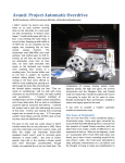
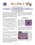
1963 Avanti Technical Article: Turner Rear Disc Brake Conversion By: Bill Henderson When I bought my Avanti last year, its brakes were so bad that I knew if I didn’t address them I’d soon be making an unscheduled visit to the body shop ‐ or worse, to the hospital. Stepping on the pedal firmly resulted in left to right weaving that needed to be controlled with white‐knuckled yanking on the steering wheel. My car was shod with its factory brakes all around, which meant its original Bendix front discs with accompanying rear drums. My conversion to Turner front discs was covered in issue #149, and the result or that operation was simply outstanding. The car stops straight and true with a perfectly firm pedal. I’ll admit that when I purchased by Turner front conversion kit, I also bought the conversion kit for the rear brakes at the same time. After all, my stopping ability was so poor, I reasoned that the back brakes must be working badly too. However, disassembly of the rear binders proved that they were in excellent shape and that there was really no need to replace them at all. And driving the car with the front disc/rear drum combination disclosed no need for an upgrade. But a true motor‐head can’t leave well enough alone, and I decided to convert them anyway to see if there would be an improvement. Besides, I reasoned, those new rear discs were not doing any good sitting in a box under my workbench. The Turner rear disc conversion is well engineered, but is in some ways a bit more difficult than the front conversion to install. While the front brakes are very much a bolt‐on affair, requiring few specialized tools or knowledge, mounting the rear brakes present a number of twists that, while not difficult for the experienced garage mechanic, make the change‐over a bit more complicated. When I converted the front brakes, I replaced the original master cylinder with a new, dual‐chamber one, and also replaced the front to rear steel brake lines and the rear junction’s rubber hose. I would strongly suggest both of these improvements before undertaking the rear disc conversion outlined here. Follow along as we perform the job aided by the step‐by‐step photos that follow. Step 1‐ Remove the road wheel. Remove the cotter pin and the center nut from the axle shaft. Use a hub puller to separate the brake drum and hub from the axle. This is the only safe way to remove the brake drum; no amount of pounding or heat will accomplish the task. Do not try to use a puller that grips the drum by its edges. You will ruin the drum and may hurt yourself. If your drums are badly worn you may want to loosen up the eccentric nuts on either side of the rear of the backing plate to allow the brake shoes to contract fully. There is a chance that the brake shoes might be sitting in a groove worn in the drum and prevent the drum from popping free. Wear a dust mask while messing around with old brakes. Save all the old parts. Even if you don’t use them, someone else might need them. These are Studebaker parts, after all. There is no need at all to waste time disassembling the brakes from the backing plate. Simply remove the brake line from the backing plate with a brake tubing wrench. I strongly suggest replacing all steel brake lines with new ones. You will need to shorten them from original anyway, and there is no sensible reason to reuse nearly fifty year old steel lines that you depend on for your life. Step 2‐ Remove the four nuts that hold the backing plate to the axle flange. Pulling the backing plate away from the axle end, twist it so the emergency brake cable can be accessed and the end detached. Here are two time‐saving tips to speed removal of the emergency brake cable. First, where the cable passes through the backing plate, a self expanding metal clip is used that sort of looks like a top hat. When pushed through the hole at assembly, it spreads out so it will not come back through. The secret to removing this clip is to slide a very small hose clamp over it, and with a screwdriver tighten the clamp until the clip compresses and the assembly slides right out of the hole. Secondly, use two pairs of vice grips to remove the brake cable from the lever it is attached to. Use one clamp to retract the spring an inch or so, baring the cable, then clamp the second pair of vice grips onto the bare cable, preventing the spring from sliding back into place. Then, using the first pair of vice grips, clamp onto the end of the brake cable and twist it free. Step 3‐ With the old brakes removed, you will find that the outer wheel bearing is exposed. Without question, now is the time to remove the wheel bearing and repack it with fresh grease, if not replacing the bearing entirely for good measure. Having to go through all of these steps to expose the bearings demonstrates why Studebakers sometimes are known to suffer from broken axles. Maintenance on the wheel bearing is skipped because it is so difficult to get to, the grease dries out, the bearing gets hot and seizes and… well, you can finish the story. Some people choose to tap and thread a grease fitting at the axle end now to allow bearings to be greased in the future without total disassembly. On the right side of the car only you will likely find a shim (or three) at the end of the axle, between the wheel bearing and the washer that covers it. These shims were installed at the factory to provide the proper axle end play. Ensure that you retain them for reassembly in exactly the same position. Step 4‐ Separate the brake drums from the hubs. If you want to absolutely ensure no damage to the old drums, use a cutoff or grinding wheel to shear the studs off flush with the drum, then use a drift and a big hammer to persuade them to let go. Instead, I used the shop press to remove them, placing a thick steel plate over top of all five studs and using gradual, moderate pressure from the ram to press on the center of the plate until the drum separated from the hub with a small bang. Before you use this method, first make sure that there are no retaining clips installed on the outer surface holding the studs to the drum. There were none on mine. This process bent the mounting flange of the brake drum inwards ever so slightly, but it can be pushed back out with the ram to make it perfectly flat once more. Step 5‐ Remove the old studs from the hub. The press makes quick work of these. Notice that the original studs are smooth and not knurled, explaining why these are known to frustratingly strip and spin on occasion. Step 6‐ Apply the tiniest amount of grease around the inside of the hole before using the press to ease the new longer studs into place. The grease will ensure that they slip in nice and straight. Step 7‐ Install the Turner kit’s caliper mounting brackets first. They go behind the axle flange, and the calipers will mount at 2 o’clock behind the axle. Pass the new bolts through the brackets first, then through the axle flange. In order, the parts are installed as follows: Wheel bearing Studebaker shim pack (if present, right side only) Studebaker large round washer with flat top New Paper gasket Studebaker factory 3/16” spacer (flat sides) Turner round washer with flat side Factory stamping outer grease seal (with integral felt washer) If your outer grease seals are the originals (like mine were) there will likely be little remaining trace of the original felt washers, whose job it once was to help keep dirt and water away from the bearings. I recommend replacing the felt washers (or as I did, replace the entire stamping complete with felt washers and gaskets included) from Studebaker International . Torque the nuts to 35 ft/lbs, then temporarily slide on the hub and the rotor and turn the wheel (assuming both wheels are off the ground and the car is in neutral) just to ensure that there is no binding. Installing the shims/washers etc. in the wrong order can clamp the wheels solidly in place. Just make sure you haven’t done so. Use a drop of red Locktite on the threads of each mounting bolt for extra safety. Step 8‐ Now reinstall the hub. Clean the axle shaft and the inside of the tapered hub thoroughly with solvent and dry them. Leaving grease on the mounting surfaces leaves you with the possibility of cracking the hub when torquing it into place. The key goes into the hub, narrow‐end‐first (so that when sliding the hub in place on the axle, the narrow end of the key contacts the axle first). Using a large socket over the end of the axle end, give the hub a couple of raps with a the heavy hammer to seat it into place. The washer and nut go on next. The nut is supposed to be torqued to 120 ft/lbs, then the cotter pin installed. You may want to wait do this when the weight of the car is back on the ground; but just don’t forget to do it! Step 9‐ Now it is time to install the caliper. Do yourself a favor and take several digital photos of the caliper right out of the box with your cell phone before you take any of it apart. If you do not, you may not remember how it goes back together. The calipers in the kit are from a 1979‐81 Cadillac Seville, the rotors from a 1984‐90 Lincoln Mark series. Make a note of this in your service manual so that when you (or a future owner) need brake parts you will know what to ask for at the parts counter. The calipers are not marked ‘right’ or ‘left’, but just remember that the bleeder screw faces INSIDE towards the center of the car, and the bleeder is at the top of the caliper and you will have it right. These are known as floating calipers, meaning the caliper and pads are allowed to “float” and center themselves to provide equal clamping pressure to both sides of the rotor when the brakes are applied. But it also means that many of the individual pieces, like the pads, have nothing to hold them in place until the entire assembly is buttoned up tight. Allow me to offer few more tips that will save your sanity and prevent you from screaming curse words as you try to assemble this Chinese Puzzle that seemingly wants to fly apart just before you get the last part in place. Use a small amount of stickum (body dum dum, or equivalent) to tack the thin steel wafer behind the inner pad. Ensure that the small round spring/clip that is between the piston and the inside brake pad does not fall out as you handle the caliper. They are easy to lose and are not available separately. Ensure both the pads are lined up and properly in place. This is a cheat—and experts who do this for a living might smirk at you, because they don’t need to use this trick. But if you are lucky enough to have such an expert around, make him do this job while you watch. On the workbench, temporarily secure the pads in place with long strips of duct tape wrapped around them, as shown in the photo. I have learned to roll the tape to ensure the face of the tape does not stick to the face of the brake pad, or it is often difficult to remove the tape and slide it out once the caliper is installed. Step 10‐ Slide the rotor over the studs and onto the hub. Make your life easier by using two lugs to loosely hold the rotor in place while you install the caliper. With the tape holding all the “floating” caliper parts together, slide the caliper onto the rotor, lining up the holes in the caliper with the mounting holes in the bracket. Once the caliper is in place but before you tighten anything, carefully pull out the tape strips that were holding everything together. Holding the floating caliper in place for dear life with one hand, slide the long Allen bolts in place that hold everything together, ensuring that the small aluminum ring spacer bushings are in the right place. Cinch the Allen head bolts nice and tight to 35 ft/lbs. Step 11‐ Now it is time to plumb the caliper. Install the “banjo” fitting of the flexible brake line supplied in the kit to the bottom of the caliper. A copper crush washer goes on either side of the banjo fitting. Get out your metric sockets: The nut is a 10mm metric fitting, and the bleeder screw is a metric size as well. Starting with store‐ bought lengths of steel brake line, I cut them down and double flared the ends to make them the proper length to mate with the flexible braided steel hoses that are supplied with the kit. Never use Teflon tape on these fittings. Brake fittings are double flared because the flare against the matching seat is what makes the high‐ pressure connection perfectly sealed. No sealing is expected from the threads, and Teflon tape may get inside the lines and contaminate the system. If you do not have a brake fitting double‐flaring tool, you can buy or rent one at AutoZone (get the SAE‐ not metric kit) or you can simply buy lines that are close enough in length and use them as they are. Use the factory steel semi‐circular clips that attach the lines to the differential case axle tubes (if they still exist on your car. I found them on mine safely buried under a half inch of greasy grime) or use the supplied plastic zip ties. Secure the lines properly so they do not move around and cause metal fatigue that might lead to a catastrophic failure someday. Step 12‐ Pictured here are original Studebaker 6” rims next to replacement Ford 15 x6 ½” rims from a 1983 to 1997 Crown Victoria, though as you can see the Ford wheels are actually nominally 1 ½” wider than the Studebaker originals. Both feature 4” backspacing (distance from the back of the wheel’s lug mounting face to the inside edge of the wheel) Because of their design, the Studebaker wheels will not clear the caliper, and so if your car has not had its wheels switched by an earlier owner already, you will need to have your tires remounted on Ford rims (MoPAR rims from mid 80’s Dodge Diplomat or full size Chrysler will work as well). 6” wide rims were used on Fords in the years just prior to this, but are now obsolete and very difficult to find new. My old tires mounted just fine on the new wider wheels. These new wheels are heavier gauge, and therefore weigh more, but are more appropriate for the radial tires that most of us use today. Some sources warn against ever using radials on the original Studebaker wheels due to their weaker design. I ordered new wheels online, and they cost me $67 each plus nominal shipping. Call it a sign of my advancing age, but I am leery of trying to find matching, straight used wheels in a junk yard, and would much rather have new ones delivered to my door by the UPS man for what amounts to a small additional cost. Avanti wheels are supposed to be off‐white in color, the correct paint is available in spray cans from our parts dealers. (Ford Wimbeldon white a legacy car and truck color is a close match and is still available in large spray cans at some auto parts retailers) Do yourself a favor and paint the wheels before mounting your tires. Yes, you may need to do some touch‐up afterwards, but that’s easier than trying to mask off tires to paint wheels that are already mounted. Step 13‐ Emergency Brake Cable: Your original emergency brake cable will be six inches too long for the new application. You can either find a brake shop to cut down the old cable, or you can order a new one from Turner. I chose the latter as the better option for me, again following my simple rule “if it is important for stopping the car and it is almost fifty years old, don’t fool around and just replace it.” (Above right) The emergency brake cable passes neatly through the eye of the rear traction bar on its way to the attachment point. My new cable length was 121”. Step 14‐ With the wheels mounted and the car on the ground and in Park, torque the hub nut to its final 170‐200 ft/lbs, then back the nut off just enough to insert the cotter pin to finish the job. Bleed the brakes thoroughly, tapping the caliper several times during to operation with a rubber mallet to dislodge any air bubbles trapped inside. Have a helper stand hard on the pedal while you carefully inspect all unions and fittings for leaks. Find a nice safe spot for your first road test, and congratulate yourself on a job well done. Conclusion Technically speaking, this Avanti now has brakes as good as any new car on the road. Compared to the factory rear drum brakes, which we disclosed were working perfectly before they were swapped off, the rear discs seem to stop the car with less grabbing and with less dive to the front under heavy braking. The pedal effort is linear and the brakes are easy to apply smoothly. In fairly aggressive braking from speeds around 40 MPH the car feels well balanced and there is no sign of premature lockup of the rear wheels even though no front‐to‐rear proportioning valve is used. Admittedly, I did not try to test performance at the limits by doing things like making repeated screaming panic stops from highway speeds or other such aggressive maneuvers, but the overall feeling after the conversion is balance and security. The design of the kit is outstanding; well engineered by Jim Turner just like the front conversion kit. I suspect that if my rear brakes were in need of repair the difference between old and new may have been more noticeable, but perhaps my test therefore is more real‐ world for those of us who keep our cars in top condition. Total time for the conversion was probably ten hours in the garage, if I did it again I could probably have completed the work in half that time, as this was my first time working with tapered axles and their associated oddities. Having the proper tools including my own hydraulic ram press saved a great deal of time, and still the job was held up waiting for the new wheels and emergency brake cable that I ordered only after the job had begun. Overall, my conclusion is that the factory rear drums do a fine job coupled with modern front discs, a well operating power booster and a modern dual‐chambered master cylinder. Given other mechanical upgrades I could have made for the same money, I would have moved this job further down on my “must have” list. However, with my conversion now complete, I now feel safe and secure with four wheel disc stopping that is state of the art. Complete Parts List Turner Rear Disc Conversion Kit www.turnerbrake.com $760 plus $36 shipping Emergency Brake Cable www.turnerbrake.com $75 (2) Ford 6 1/2" OEM Steel Wheels www.wheelsandcaps.com STL1234U45 $162 Wheel Paint (2) Outer Rear Wheel Seals w/felt washers www.studebaker-intl.com 800082 $13 www.studebaker-intl.com 533161 $40 New rear steel Brake Lines AutoZone or other $10 New Wheel Lugs for Ford Wheels AutoZone or other $20 local auto shop $45 Tire Mounting and Balancing Total Cost of Parts $1,086 Don't forget that your original Studebaker spare tire will not fit your rear wheels. Consider a replacement now. Special tools needed: There are a few tools that are used to complete this job that are may not be commonly found in a standard toolbox. 3/8” Allen Head Hex Wrench: This is a king‐sized Allen wrench that is not found in a typical tool kit. They are needed to install the brake calipers. You can also get a 3/8” hex socket for your ratchet wrench that will do the job at the auto parts store. Hub Puller: one designed for use on a front wheel drive car will work just fine. I got mine at Auto Zone for $25, and they will allow you to return it after use if you want and get your money back. Since it is needed any time the rear drums have to come off, I decided to keep it for future use. Cutoff Wheel: It is nearly impossible to remove the frame‐mounted emergency brake cable guides without cutting the nuts off the bolts. The bolt heads are stuffed so tightly inside the frame rail that trying to wedge a wrench into this spot to remove them would have wasted hours. I simply cut the old ones off with my air tool and moved on. You may also choose to use the grinding wheel to cut the old studs off flush with the brake drum to aid in removing the hub from the drum Hydraulic Ram Press: To remove and install the wheel studs into the hubs, and potentially to press the old brake drum off the hub. If you don’t have one of these (available these days at Harbor Freight for well under $200) or take these to your auto repair garage and have them do it for you. Brake tube fitting wrenches – every garage mechanic should have a set of these Tube cutter and Brake tube double flaring tool (optional) Author Information: Bill Henderson, [email protected]