1
Maintenance Procedures
Mfr.
Description
Page
Date Issued:
AA
Modulus II Plus w/ 7810 Ventilator
7 of 27
10/27/95
Revision Date:
07/2004
E.
Scavenging System Checks
NOTE:
1.
2.
F.
The old style relief valve may allow a negative pressure indication up to -2
cmH2O. If you find an old style relief valve, replace it with the new style valve
assembly.
Check and/or replace as necessary:
a. 1/4 inch vacuum hose.
b. All unused evacuation ports must be capped.
c. Evacuation hoses.
d. Three (3) liter evacuation bag.
e. 19 mm scavenger tee for gas monitors.
f. Ensure that the double 19 mm connector, if fitted, is located beneath the scavenger
valve.
Inspect and Clean
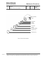
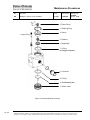
a. Remove positive and negative relief valve components.
b. Clean inside of manifold and beneath negative pressure button.
c. Clean needle valve and seat assembly. Lubricate the needle valve threads w/ Krytox, as
necessary.
d. Replace positive and negative pressure gaskets as needed.
e. Reassemble the valve.
GMS Inspection
NOTE:
MP 1014
Number: 3.00
For units manufactured prior to 1986, verify that the Inhalation Port pressure
sensing nipple, a raised head gasket, a drain valve for adjustable height bag
arms, and check valve disk retainers with stand offs are installed.
1.
(EVERY 24 MONTHS) Manifold Inspection
a. Remove the access screen. Replace the cup seals every 24 months. Looking through
the access screen opening, inspect the GMS manifold for contamination. If
contamination is present, remove the manifold and clean or replace components as
necessary.
2.
Periodic Inspection
a. Gauge
1)
Remove the gauge assembly and inspect the O-ring; replace as necessary.
Insert the gauge assembly into an approved test device (see tools appendix).
2)
Verify the accuracy of the gauge at:
0 ± 1 cmH20 (0 ± 0.7 mmHg)
40 ± 1 cmH20 (29.4 ± 0.7 mmHg)
-5 ± 3 cmH20 (-3.7 ± 2.2 mmHg)
3)
Ensure that the patient pressure sensing line is attached to the test device.
Verify that the ventilator's sub-atmospheric pressure alarm activates at -10 ± 5
cmH20 (- 7.4 ± 3.7 mmHg).
4)
Return the gauge assembly to the absorber.
5)
Ensure that the pressure sensing line is attached to the absorber.
The information contained in this document is CONFIDENTIAL INFORMATION and IS INTENDED ONLY FOR THE USE OF EMPLOYEES OF
GENERAL ELECTRIC COMPANY, IT’S SUBSI DIARIES, AFFILIATES OR DESIGNEES. Distribution or copying of this document by nonemployees or non-designees is strictly prohibited without the express written consent of General Electric Company or subsidiary thereof.