1
Now that the instrument cluster has successfully been connected
to the CAN bus, we can configure the node that will be
responsible for transmitting data to the instrument cluster unit.
This node will be acting as a rogue device that an attacker could
use to interact with components on the CAN bus in nefarious
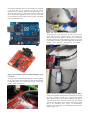
ways. We will be using an Arduino Uno Rev 3 and a CAN-Shield
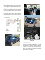
to achieve this (Figure 2-10).
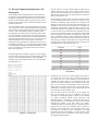
Figure 2-11: CAN shield used to connect to CAN bus
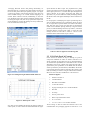
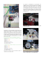
The Arduino will be powered from the same 12V DC power
source that powers the instrument cluster. The Arduino Uno
features a built in voltage regulator at the power port. Considering
the safety benefit of the voltage regulator, applying 12V of power
to the Arduino was not an issue as the Arduino Uno specifications
explicitly state that the microcontroller can handle a
recommended 7 - 12 volts (Figure 2-12).
Figure 2-10: Arduino Uno and CAN shield simulating a rogue
CAN device
To interface the CAN shield with the data bus, we will be splicing
the 18 gauge twisted pair wire from the CAN bus and soldering
CAN-H and CAN-L wires coming into the pins on the CAN
shield as shown in Figures 2-11.
Figure 2-12: 12V power source and Arduino voltage regulator
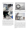
In order for the Arduino to keep track of accurate time, even when
the power is disrupted, we will use a real time clock module
(RTC). The RTC chip is powered with a small battery in order to
retain the current time in the event of power loss. The Arduino
will poll the time from the RTC in order to transmit the accurate
time to the instrument cluster gauges. For demonstration
purposes, we placed the RTC on a bread board separate from the
Arduino (Figure 2-13).