1
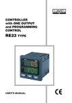
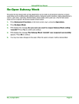
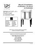
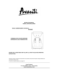
MICROPROCESSOR PROGRAMMER -CONTROLLER RE15 USER’S MANUAL CONTENTS 1. APPLICATION ....................................................................4 2. CONTROLLER SET ...........................................................6 3. INSTALLATION AND BASIC SAFETY REQUIREMENTS . 7 4. SERVICING . .....................................................................14 5. CONTROLLER PARAMETERS .......................................19 5.1. List of parameters..........................................................19 5.2. Kinds of alarms..............................................................27 5.3. Pulse repetition period...................................................28 5.4. Linear additional input...................................................28 5.5. Binary input....................................................................29 5.6. Three-state control.........................................................30 5.7. Three-state step by step control....................................30 5.8. Security code.................................................................31 6. SPECIAL FUNCTIONS .....................................................32 6.1. Calling of special functions............................................32 6.2. Manual control...............................................................32 6.3. Selection of PID controller settings................................33 6.4. Measurement of the two-wire line resistance................33 6.5. Retreat to the producer settings....................................33 7. PROGRAMMED CONTROL .............................................34 7.1.Defining set point programs............................................34 7.2. Control by set point program.........................................36 8. SELECTION OF PID SETTINGS ......................................37 8.1. Self-adapting control system .......................................37 8.2. Manual selection of PID settings .................................39 9. TECHNICAL DATA ...........................................................41 10. EXECUTION CODES AND ORDERING . ........................45 11. MAINTENANCE AND GUARANTEE . .............................46 1. APPLICATION The RE15 microprocessor controller is destined to control the temperature or other physical quantities, e.g. pressure, humidity, level, converted into an electric signal. The set point can be constant, changed during the process operation or read out from the additional input. 15 programs of the setpoint are available. Measured values, set point, output signal and program parameters are displayed on two displays and two bargraphs. The controller has four outputs enabling the continuous control, twostate control, three-state of heating-cooling type control, three-state step-by-step control, alarm signalling and retransmission. The binary input serves to control the set point or to switch over on the manual operation. The function of the automatic selection of PID controller settings ensures a satisfactory control quality. The RS-485 interface with MODBUS protocol gives the possibility to apply the controller in control systems. Features General: - dual displays (4 digits with 7-segments each), - the upper red, to display the process value , - the lower green, configurable for display the setpoint, control power, measured value at auxiliary input, state of digital input or program parameters, - two bargraphs (red and green) 21 points each, configurable to display control power, setpoint or process value, - four indicators for outputs state, - four buttons to configure the controller, Inputs: - up to 2 analogue inputs, each sampled twice a second, - universal configurable main input: The input will accept all standard thermocouples, the Pt100 resistance thermometers, milliamps or volts, - auxiliary linear input configurable for remote setpoint or for an additional process value for control (sum or difference or average to main input) or for extra measurement (for example a position feedback potentiometer at motorized valve control), - digital input (non-voltage contact) for remote program control - stop/run, hold, reset input is active when closed. Outputs: - four outputs (see ordering code), - up to 2 analogue outputs - configurable 0-10 V, 0-5 V, 0-20 mA, 4-20 mA, - each output can be configured as control output or alarm or retransmission (analogue only), or event output, Digital communications: RS485; MODBUS ASCII and RTU protocol Setpoint: - local with soft start - remote from auxillary input - ramp/soak: 15 programs Control: - The RE15 can be configured for heating, cooling, heating/cooling , cooling/cooling or for motorised valve control. The valve control algorithm does not require a position feedback potentiometer. Programmer parameters: - 15 programs, - 15 segments per program, - ramp segments 0.1...999.9 units/min., - soak segments 00:01...99:59 minutes, - event outputs at segments, - start at process value, - holdback function, - number of cycles 1...99, Alarms: - number : 0...4, - deviation :high, low or band, - full scale : high or low, - full scale: main or auxiliary input, - sensor break alarm, - latched : on or off - hysteresis: 0...99.9 units Extra functions: - two selectable autotuning algorithms are available: with the load cool and at the setpoint. They calculate PID settings for accuracy control, - retransmission of the setpoint or PV; configurable span, - two security codes protect all (except setpoint) parameters, - hand or automatic mode with bumpless switching, - reset to factory settings, A setup program CONTROL is available for easy configuration from a PC. 2. CONTROLLER SET The controller set includes: - RE15 controller - service manual - guarantee certificate - holders - seals - interface service manual 1 pc 1 pc 1 pc 4 pcs 1 pc 1 pc 3. INSTALLATION AND BASIC SAFETY REQUIREMENTS One should insert the controller in the prepared hole (92+0.6 x 45+0.6) mm in the panel which dimensions are given on the Fig. 1 and fix it by means of four holders (delivered with the controller). The panel thickness cannot exceed 15 mm. 92 +0.6 45 +0.6 Panel cut-out Fig. 1 Overall and panel cut-out dimensions The RE15 controller fulfils requirements concerning the service safety in accordance with EN 61010 standard and EMC immunity against interference occurring in the industrial environment containing a certain amount of noise in the form of transient voltages and spikes, according to EN 61000-6-2 standard. Different interference sources practically occurring influence the controller indications in a continuous or pulse way from the side of the main supply (as the result of other device action) and also overlaps the measured signal or controller auxiliary circuits. Interference also arises as the result of switching capacitanceinductive loads by own controller relays. In particular, important impulse interference are dangerous for the device operation because they can cause sporadic wrong measurement results or accidental alarm operations, despite the application of appropriate filters in the controller. The noise level should be reduced to a value lower than the controller immunity threshold, first of all through an appropriate controller installation in the object. In order to obtain a full controller immunity against electromagnetic interference in the environment with an unknown noise level it is recommended to observe following principles: • do not supply controllers from the mains in the proximity of devices generating important impulse interference, • use network filters for the group of controllers servicing the same • object, to lead supply conductors, use metallic screens in the shape of conduits or braids, in which one can also lead the ground conductor and the mains conductors of the given controller alarm relays. • lead individually the connections of the communication interface circuits in a screen as above, with twisted conductors, • conductors leading measuring signals to the controller should be of twisted-pair construction, and for resistance thermometers in three-wire connection, twisted with conductors of the same length, cross-section and resistance, and led in a screen as above. • apply the general principle that conductors (group of conductors) leading different signals should be led in the greatest distance from each othere ( not less than 30 cm) and crossings of such conductors must be executed at right angle. In the controller rear part there are two sockets of terminal strips, to which the mains and external circuits are connected. Electrical connections must be carried out acc. the Fig.2. E Interface GND A B Binary input Additional input Input or input signals 16 15 14 13 12 11 10 9 8 7 6 5 4 3 2 1 17 18 19 20 21 22 23 24 25 26 27 28 29 30 31 32 Supply Output 1 Output 2 Output 3 Output 4 a) Description of the terminal strips Resistance thermometer in a two-wire connection or resistance measurement Thermocouple Resistance thermometer in a three-wire connection Current input 0/4...20 mA Voltage input 0/5...10 V Additional current or voltage input Additional potentiometric input Binary input b) Input signals Relay outputs 10 Current outputs or OC Voltage outputs c) Output signals d) RS-485 interface Fig.2 Electric diagrams of the controller 11 Basic requirements and user’s safety RE15 controllers are intended to be installed into panels, switchboards and cubicles. They are in conformity with IEN 61010-1 standard for safety requirements. Remarks concerning safety: The installation should be carried out by a qualified staff. One must consider all accessible aspects of the protection. The controller lefts the factory in perfect condition regarding technical safety. In order to maintain this condition and to ensure a safe operation, the user must comply with indications and markings contained in the service manual and following instructions: • Before installation or beginning any trouble shooting procedures the power to all equipment must be turned off and isolate. Units suspected of being faulty must be disconnect and removed to a properly equiped workshop for testing and repair. • Component replacement and internal adjustments must be made by qualified maintenance personnel only. • • Before mounting, ensure that the operating voltage and mains voltage are the same, and then proceed with installation. The power supply must be connected as shown in the relevant diagram. • Before the turning-on, check the correctness of all connections. • Before any maintenance and/or repairs, whenever the instrument must be opened, it must be disconnected from all power sources. 12 • Do not use this controller in areas subject to hazardous conditions such as excessive shock, vibration, dirt, moisture, corrosive gases or oil. The ambient temperature of the areas should not exceed the maximum rating in the Technical Data chapter. • If there is ever the suspicion that safe use is no longer possible, the instrument must be taken out of service and precautions taken against any accidental use. • Operation is no longer safe when: - there is clearly visible damage, - the instrument no longer functions, - after lengthy storage in unfavourable conditions, - after any serious damage incurred during the transport. Operator safety The controller described in this service manual is intended for use by properly trained staff only. All wiring must be conform to appropriate standards of good practice and local codes and regulations. Wiring must be carried out only by authorised personnel. For proper, safe use of the instrument and for maintenance and/or repairs, it is essential that the persons instructed to carry out these procedures follow normal safety precautions 13 4. SERVICING The frontal plate of the controller is shown on the Fig. 4 Fig.4. View of the controller frontal plate 14 Push-button functions: - change of set point or the program number - calling the menu of working parameters (3 sec), - entry into the parameter change mode, - acceptance of the introduced data. - display of the next parameter, - increase of the parameter value. - display of the previous parameter - decrease of the parameter value, - calling of special functions (3 sec.). - return to the previous level, - resignation of introduced changes, - calling of the menu of controller configuration. The controlled value is displayed on the upper display. The controlled value is the value measured on the main input or the sum, difference or arithmetic mean of measured values on both inputs (parameter fjn2 set on the value and, djff, or sred) is displayed on the upper display. The set value or process parameters marked by an appropriate symbol are displayed on the lower display: - h driving signal of the channel I, - c driving signal of the channel II (cooling), - a measured value on the main input (when the controlled value is the function of two inputs), - u measured value on the additional input, - b state of the binary input (when finb off), - prnumber of the performed program - n number of the realised section during the programmed control, - t time which remains till the end of the section in the programmed control, - l quantity of cycles which remains to end the operation. 15 On fig. 5 and 6, the diagram of controller servicing is presented suitably for constant-value and programmed control. Mode I: Process control upper display - measured value lower display - set point bargraphs - quantities defined by bar1 and bar2 Push-button functions: Process parameters depended on the configuration are shown on the lower display and: h control signal of the line I1) c control signal of the line II (cooling) a value on the main input (when the controlled quantity is a function of two inputs) u measured value on the additional input b state of the binary input (when finb off) 2) and stop/control renew and erasing of stored alarms 3 sec. Change of set point Made III: change and/or review of controller operation parameters (see table 3) pid PID parameters for line I pidc and Hn parameters for line II3) naro change speed of set point alr parameters for alarm outputs rsp kind of set point seCp security code during 3 sec. Mode II: controller configuration (see table 2) - inp1, t_li,r_li, conp, - lcpp - shif, spll, splh - inp2, i2lo, i2Hi,fin2 - finb - ouc1, ouc2 - out1, out2, out3, out4 - bar1, bar2 - adre, baud, tryb - auto - cont - seCc Mode IV: Special function To call the suitable function, press and next ste1 manual control of input 1 ste2 manual control of input 2 ste3 manual control of input 3 ste4 manual control of input 4 adap automatic selection of PID parameters r-li resistance measurement of the 2-wire line nfab return to manufacturer’s settings 1) flashing of the control signal of 0.0 value means, that the automatic control has been disabled by and push-buttons. 2) after pressing and push-buttons, the inscription stop appears for 2.5 sec on the lower display when the control is disabled, or ctrl, when the control was renewed. 3) parameters appears only for the control with two lines. Fig.5. Service diagram for the constant valued control (rsp= con) 16 Mode I: Process control Upper display - measured value Lower - set point Bargraphs - quantities defined by bar1 and bar2 Push-button functions: Proces parameters depended on the configuration are shown on the lower display and: pr number of operating program n number of the operating segment t timeremaining till the segment end l number of cycles which remain to operate and starting the program from beginning2) and program jump to the next segment 3 sec. and stop/control renew2) and erasing of stored alarm 3 sec. Nrpr change of the operating program number4) Mode III: change and/or review of controller operation parameters (see table 3) pid PID parameters for line I pidc and Hn parameters for line II3) pro9 program defining (see table 4) alr parameters for alarm outputs rsp kind of set point seCp security code Mode II: Controller configuration (see table 2) - inp1, t_li,r_li, conp, - lcpp - shif, spll, splh - inp2, i2lo, i2Hi,fin2 - finb - ouc1, ouc2 - out1, out2, out3, out4 - bar1, bar2 - adre, baud, tryb - auto - cont - seCc Mode IV: Special functions To call the suitable function, press and next ste1 manual control of input 1 ste2 manual control of input 2 ste3 manual control of input 3 ste4 manual control of input 4 r-li resistance measurement of the 2-wire nfab return to manufacturer’s settings 1) flashing of the control signa ofl 0.0 value means, that the automatic control has been disabled by and push-buttons 2) when the programmed control is operating the dot in the right lower display corner is flashing, however when the control is disabled, the point is extincted. 3) parameters appears only for the control with two lines. 4) the number of the operating program can be changed only when the program is stopped or finished. The acceptation of a new number causes the start of the selected program from the beginning. Fig.6 Service diagram for the programmed control (rsp=pro9) 17 After the mains turn-on the program version is displayed. After the first turn-on, the Pt100 sensor is set. If another sensor is connected to the controller, one must change theinp1. parameter. The set point is adjusted on the beginning of the measuring range The parameter change follows after pressing the key: • for numerical parameters; the less significant digit is flashing, change the value by means of and keys. The acceptation of the introduced value follows after pressing the key. The change of the number value is carried out in the range defined for the changing parameter. • for non-numerical parameters the whole lower display is flashing. After pressing and keys, successive inscriptions defined for the changing parameter appear on the display. The acceptance of the introduced value follows after pressing the key, the resignation of introduced changes after pressing the key. In case of any abnormality appearance in the controller operation or error in electrical connections an appropriate error code appears in the upper display. Error codes Error code 18 Table 1 Reason Solution ler1 Shorting in the sensor circuit or Change or correctly connect the exceeding of the lower measu- sensor, check if the type of the selecring range on the main input ted sensor is in conformity with the connected one, replace the sensor Her1 Break in the circuit, lack of sensor or exceeding of the upper measuring range on the main input. Change or correctly connect the sensor, check if the type of the selected sensor is in conformity with the connected one, replace the sensor ler2 Shorting in the sensor circuit or exceeding of the lower measuring range on the main input Change or correctly connect the sensor, check if the type of the selected sensor is in conformity with the connected one, replace the sensor Her2 Break in the circuit, lack of sensor or exceeding of the upper measuring range on the main input. Change or correctly connect the sensor, check if the type of the selected sensor is in conformity with the connected one, replace the sensor 5. RE15 Controller parameters 5.1. List of parameters Parameters are set together in tables 2 and 3. Parameters concerning programs of the set points are presented in the table 4. List of configuration parameters - Mode II Table 2 It. Parameter name Symbol on the display Manufacturer setting inp1 pt1 1. Kind of input 5) Range of changes Explanations pt1 pt10 nj1 Cu1 t_i t_t t_H t_s t_r t_b t_e t_n t_ch rr-r 0-20 4-20 0-10 0-05 Pt100 Pt1000 Ni100 Cu100 Thermocouplet J Thermocouplet T Thermocouplet K Thermocouplet S Thermocouplet R Thermocouplet B Thermocouplet E Thermocouplet N Thermocouple chromel-kopel 0...400 Ω 0...20 mA 4...20 mA 0...10 V 0...05 V 2-wire line 3-wire line 2. Type of line t-lj 2-p 2-p 3-p 3. Resistance of 2-wire line r-lj 0.0 0.0...20.0 Only for resistance thermometer inputs 4. Compensation Conp of temperature cold jontions - for thermocouples auto auto - automatic compensation 0.0...50.0°C - temperature of cold jonctions auto = -0.1 or 50.1, 5. Number of digits after the decimal point - concerns, measured values. 0 0,1,2 lcpp 6. Shift of measured shjf 0 -999...999 1) value on the main input 0- without decimal-coded digit 1-with one digit after the decimal point 2- with two digits after the decimal point (only for linear inputs) Parameter added to the measured value - compensation of the temperature difference between the sensor and the object. 19 It. Parameter name Symbol on the display Manufacturer setting Range of changes -200 -999... Explanations 7. Lower range of 5pll the set value or measured value on the main input. 8. Upper range ...splH1) 5plH 850 spll... ...99991) upper range, e.g. 20mA. For resistance thermometer inputs, SpLL and SpLH parameters limit the range of the set value. inp2 0-20 0-10 100 0-20 4-20 0-10 0-05 100 1000 0-20 mA for current inpu 4-20 mA for current inpu 0-10V for voltage input 0-5V for voltage input 0...100 for potentiometer input 0...1000 for potentiometer input 0.0 -999... These parameters allow to ...j2Hj1) display the measured quantity on the additional nput in physical units. 100.0 j2lo... ... 99991) - asabove 9. Measuring range of the additional input 10.Value correspon- j2lo ding to the lower measuring range of the additional input. 11. Value correspon- j2Hj ding to the upper measuring range of the additional input. 12.Function of the fjn2 info sp7) additional input. info and djff sred 20 For linear inputs, spll and splH parameters allow to display measured values in physical units i.e., the SPLH value corresponds to the lower input range , e.g. to the 0 mA value, however, the SpLH value corresponds to the - Set value (rsp = inp2) - Additional information - measurement = sum of signals from the both inputs - Controlled value=difference of signals from the main input and additional input - Controlled value=arithmetic mean of the both inputs It. Parameter name Symbol on the display Manufacturer setting Range of changes Explanations 13. Function of the fjnb off off binary input stop hand end bloh No used binary input Stop the control (control signal = 0 ) 14. Ranges of continuous outputs ouc1 0-20 ouc2 0-20 4-20 0-10 0-05 0- 20 mA for current outputs 4 -20 mA for current outputs 0-10 V for voltage outputs 0- 5 V for voltage outputs 15. Output functions out1 out2 out3 off y1 y2-c2) No used output Control signal of channel I Cooling (heating-cooling control) y1 ahj alo out4 err1 y2-s2) ahj alo dbhj dblo dbhl dbjn ahj1 alo1 ahj2 alo2 eout eop err1 err2 trj1 trj2 trsp End of the programme. Stopping of the programme on the last calculated set value. Closing (three-state, step-by-step control ) absolute upper alarm absolute lower alarm relative upper alarm relative lower alarm external relative alarm relative internal alarm absolute upper alarm from main input absolute lower alarm from main input absolute upper alarm from additional input absolute lower alarm from additional input binary channel used in programmed control signalling of the program end signalling of failures of the main input signalling of failures of the input additional retransmission of the measu- red value from the main input retransmission of the measu- red value from the additional input retransmission of the set valuer 21 It. Parameter name Symbol on Manufacturer Range of the display changes setting 16. Bargraph bar1 t1 y1 functions bar2 5p y2 t1 t2 5p 17. Controller address adre in the network 0 5) 18. Baud rate in baud 9600 5) bit/s 0...247 Explanations Control signal Y1 0...100% Control signal Y2 0...100% Measured value from the main input3) Measured value from the additional input 4) Set point3) For executions with interface 2400 4800 9600 19. Interface working tryb off5) off mode a7e1 a7o1 r8n2 r8e1 r8o1 r8n1 20. Algorythm of auto off off setting choice jden oscy off Off 21. Continuation of cont Off - transmission blocked a8n1 A- ASCII mode r - RTU mode 8 or 7 bits of data E - parity check o - odd parity check n- lack of parity check 1 or 2 stop bits Algorythm switched off Method of object identification Oscillation method Control switching off after constant valued control after a on switching the supply on 6) Control switching on after supply decay 22. Safety code for 5eCc 0000 0000... the configuration ...9999 switching the supply on 6) When 5eCc>0000, then the application of its value during the parameter change is required. 1) The range and the parameter format are depending on the lcpp parameter - number of digits after the decimal point. 2) y2-c and y2-5 outputs exclude themselves reciprocally, because algorythm of the three-state heating-cooling control and three-state step-by-step control can not be realised simultaneously. 3) The value is displayed in the splL...splH range, i.e. 0% of lighted bargraph segments corresponds to values lower and equal to spll, 100% of lighted bargraph segments corresponds to values higher and equal splH ( 21 lighted bargraph segments ). 4) The value is displayed in the range j2lo...j2Hj 5) Parameters are not changed after calling the function ”Return to the Manufacturer settings” 6) One can renew the stopped control by pressing simultaneously The control can be stopped by pressing simultaneously 7) and i keys. keys. When the rsp parameter is set on inp2 then fin2 assumes the sp setting and does not submitted to change. 22 List of work parameters - mode III It. Parameter name 1. PID parameters for the line I Symbol on Manufacturer Range of the display setting changes par pjd2) 1.1 Proportional band pb 10.0 0.. of the line I 999.9% Defines the interval below the set value, in % of the measuring range, in which the control signal is proportional to the control deviation. When pb = 0, the ON/OFF type of control is chosen. 0...3600 s Time necessary to double the signal issuing from the proportional part. When tj= 0, the integration element is switched off. 1.3 Differentiation time td 60 0...1000 s Time necessary to equalize the signal issuing from the proportional part with the signal issuing from the differentiating element; When td=0 the differentiating element is switched off. 1.4 Correction of the y-of 0.0 0.0... control signal for 100% ti=0 For the control of P or Pd type (the integration time -constant ti=0) the value added to the control signal in order to compensate the control constant deviation. 1.2 1.5 Integration time constant of the line I Table 3 Explanations Pulse repetition period of the line I tj to 300 20 1...250 s Period in which the time of the control output I action is proportional to the control value. Only for discontinuous outputs. 23 Parameter name It. Symbol on Manufacturer Range of the display setting changes Explanations 1.6 Hysteresis H 1.0 0...99.91) of the line I Interval around the set value in which changes of the input quantity does not generate changes of the main output state. The parameter is active, when the control of ON/OFF type was chosen. 1.7 Kind of control in the line 1 Reverse control Non-reverse control typr jnu jnu djr 2 PID parameters for par the line II 2) 2.1 Proportional band pb-c 10.0 of the line II pjdc 0... 999.9% Occurs when one of the output is set as cooling (y2-c) Defines the interval above the set value for cooling, in which the control signal is proportional to the control deviation. When pb-c = 0, then the ON/OFF type of control is chosen. 2.2 Integration time-constant of the line II tj-c 0 0...3600 s As for tj 2.3 Differentiation time-constant of the line II td-c 0 0...1000 s As for td 2.4 Hysteresis Hj-c 1.0 0..99.9 1) When the control in the for the line II line II is of ON/OFF type. 2.5 Pulse repetition to-c period of the line II 3 24 Dead band Hn 20 1...250s Explanations as for to to 10.0 0...99.91) For step-by-step control of the set value. For the three-state heating-cooling control, the parameter added to the set value for the line I defines the set value for the line II (cooling). It. Parameter name 4 Speed of set point changes, i.e. soft start for the constant -valued control Symbol on Manufacturer Range of the display setting changes naro 0 Explanations 0...999.9 Enables to a soft access units/minute from the present tempera- ture to the set point after connecting the controller to the network or after changing the set point when it is equal 0, then the function is disabled. 5 Alarm parameters2) par alr 5.1 Set value for the alarm Xasp splH x-output nr splH1) Value generating the action of the alarm output. 5.2 Memory xaHj 1.0 0.0... of the alarm x-output nr 99.91) Interval around xasp, in which changes of the input quantity does not create changes of the alarm state. 5.3 Alarm memory Xapa off off x-output nr on Alarm memory switched off Alarm memory switched on rsp con 6 Kind of set point con prog9 inp2 Constant - valued Programmed With auxiliary input 7 Security code 0...9999 seCp 0 Definition of set point programs It. Parameter name Symbol on Manufacturer Range of the display setting changes Table 4 Explanations 1 Number of the nrpd11...15 defined program Review or definition of the shown set point program 2 Number of lcyc11...99 program cycles Number of program repetitions 3 Value of the control bloh 0 0...9991) deviation blocking the set point counting Value of control deviation over which the counting of set point is stopped. When the parameter is 0, then the blocking is inactive. 25 It. Parameter name Symbol on Manufacturer Range of the display setting changes 4 Index to continue cont off the program after the supply return off on Explanations Stop the program Continue the program 5 Speed of set point naxx 0 0,0...999,9Accretion rate od descent changes unit/min rate of set point. When parameter = 0, then the set point is constant in the segment. (stop). xx - number of the segment 1...15 0 splh 6 Set point at the spxx end of the segment For segments, in which the parameter nAxx is different from o, the in-coming set point - at the segment end. 7 Segment duration txxx 0 0...999 minSegment duration with a constant set point (for segments in chich the parametr nAxx is equal 0) Caution ! Both parameters nAxx and t xx equal 0 means the end of the program. 8 Binary output state eoxx off on...off k in the segment xx,k k=1...4 - number of the output configured as eout 9 Index of blocking blxx on...off on...off in the segment xx State of output k connection in the segment xx on - active blocking off - inactive blocking Index of blocking activity in the segment xx on - active blocking off - inactive blocking The range and parameter format depend on the parameter lcpp - the number of digits after the decimal point. 1) 2) Press the 26 push-button to enter into the menu. 5.2. Kinds of alarms During the output configuration (parameters out1...out4), one must define which of outputs operates as alarms, and alarm types. The value of alarm operation on the output x is given in the parameter xasp (fig. 7). The xasp value means : - for absolute alarms ah1 and alo - value of controlled signal - for absolute alarms ahi1 and alo1 - value measured on the main input. - for absolute alarms ahi2 and alo 2 - value measured on the additional input. - for relative alarms dbhi, dbLo, dbhl and dbin - value of the control deviation. The drawings below describe alam types: a) b) c) d) e) f) Fig.7. Kind of alarms a) absolute upper ahj b) absolute lower alo c) relative upper dbhj d) relative lower dblo e) relative external dbhl f) relative internal dbjn 5p- set point xAsp - set point on the output x 27 5.3. Pulse repetition rate The pulse repetition period is the time which expire between successive switchings of the discontinuous output during the proportional control. The length of the pulse repetition period can be chosen depending on the dynamic properties of the object and appropriate to the output device. For fast processes, it is recommended to use SSR relay or a continuous output. The relay output is used for steering contactors in slow-changing processes. the use of long pulse repetition periods for steering high-frequency processes can give undesirable effects in the shape of oscillations. In theory, smaller the pulse repetition period, better the control is, however for the relay output it should be as high as possible in order to prolong the relay life. Recommendations concerning the pulse repetition period. Output device (output 1 or output 2) elektromagnetic relay Table 4 Pulse repetition period (to or to-c) Load (resistance) Recommended >20 s min. 10 s 2 A/250 V AC or contactor min. 5 s 1 A/250 V AC transistor output 1...3 s Solid-state relay (SSR) 5.4. Additional input. In the controller, which is equipped with an additional input, one must set parameters: inp2, i2lo, i2Hi and fin2 defining the input type, measuring range and the function (see table 2). This input can fulfil following functions: - Source of remote set point (rsp = inp2), then fin2 = sp and do not be subject to changes, only the set rsp on the con or pro9 allows the selection of remainding functions. - The additional measurement fin2 = info, e.g. information about the valve opening state. The measured value on this place and recalculated on the range (i2lo...i2hi) is displayed on the lower display, preceded by the symbol u. 28 - As the component of the controlled signal: fin2 = and, fin2 = diff, fin2 = sred, the controlled value = sum of signals from both inputs WR = I1 + I2 the controllled value = difference of signals from the main input and additional input. WR = I1 - I2 the controlled value = arythmetic mean from both inputs WR = (I1 + I2)/2 in this case, there is the controlled signal WR on the upper display, and individual measurements are displayed on the lower display preceded by symbols: a - measurement on the input 1 u - measurement on the additional input. 5.5. Binary input The binary input is used according to the parametr setting finb, where: stop - disabling of control outputs and relative alarms, hand - impuls switching on the manual operation, end - end of the program and return to its beginning, bloh - stop of set point counting and the control follows acc. to the last calculated value. For stop and bloh the above action is carried out, when the binary input is shorted (on). The input opening (off) causes the controller return for the operation mode. For hand, the state switching from off to on produces the entry of the control output (y1 function) into the manual control. The next switching from off to on produces the return to the automatic control. For end, the state switching from off to on produces the end of the program, and the state switching from on to off causes the program start from the beginning. 29 5.6. Three-state control The three-state control is used during heating and cooling. One must set the parameter outk on the value y2-c and set the zone of the channel separation Hn. The second line operates for the set value equal sp+Hn as a non-reverse controller. One must define parameters pb-c, tj-c , td-c, Hj-c, to-c in accordance to the table 3. The operation of a three-state controller with the algorythm of P type is shown on the fig.8. output 100% line II - cooling (y2-c) line I - heating (y i) pb sp Hn pb-c input Fig.8. Three-state heating-cooling control 5.7. Three-state step-by-step control The three-state step-by-step control is used to control a valve. One must set the outk parameter on the value y2-5 and set the dead-band around the set value Hn. The first line - opening the valve - operates for the set value equal sp-Hn/2 as a reverse controller, the second line - closing the valve - operates for the set value equal sp+Hn/2 as a non-reverse controller. PID parameters for the second line are the same as for the first line. For the step-by-step control a control of PD type is recommended. The operation of a three-sate step-by-step controller with an algorythm of P type is shown on the drawing 9. 30 output 100% line I - opening (y i) line II - closing (y2-s) sp pb Hn pb input Fig.9. Three-state step-by-step control 5.8 Security code s e C c parameters - for configuration parameters and s e C p for working parameters of the controller - allow to secure the controller against the interference of incompetent persons. The security codes are switched off by the Manufacturer, i.e. they are equal 0. After setting all necessary parameters and after checking the correctness of the controller operation, one can set the security codes. After setting the code, the change of parameters is preceded by the necessity to give its value. Only the change of the set value is directly accessible. In order to change the security code, one must give the hitherto existing seC1 , value, and next, introduce the new seC2. If an incorrect code has been given, the err5 inscription is displayed till the moment of pressing any optional key. 31 6. SPECIAL FUNCTIONS 6.1. Calling of special functions One must hold during 3 s the key (see Fig. 5 - entry into the mode IV), and then by means of and keys select the appropriate function. The return to the mode I follows after pressing . 6.2. Manual control The manual control is useful during setting to work the control on the object and for identification the object parameters. One can manually control any optional input by calling the stek function (mode IV), where k means the output number. The measured value is shown on the upper display, and on the lower display, depending on the kind of output: - for a two-state control (output k as y1 or y2-c) The value of the output signal is flashing on the lower display, and one can change it by means of or key in the range 0.0...100%. - for the alarm or signalling device The turning-on (on) or turning-off state (off) of the outputare on the lower display. - for step-by-step control The valve opening is carried out during the key, holding, the valve turn-off is carried out during the key holding. The valve state is given on the lower display: open- turn-on, clos- turn-off, stop - valve stop. The return to the automatic work follows after pressing the key. 32 6.3. Selection of PID controller settings The adap function appears on the list of specjal functions when the auto parameter (mode II) is set on the value iden or oscy. The change of lewer display displays from off on on calls the algorythm of automatic selection of PID control settings. 6.4. Measurement of a two-wire line resistance In controllers with resistance thermometer sensors connected by a two-wire line one should introduce the line resistance value - ( parameters 2 and 3 in the table 2), or measure in accordance to the following procedure: shorten the sensor terminals, entry into the mode IV and call the r_ljfunction, the measured resistance value is flashing on the lower display. After the value stabilisation,accept it by the key. A lead resistance higher than 20 Ω will not be accepted. 6.5. Return to the producer settings Producer setting can be restored after entering into the mode IV, calling the nfab function and accepting the value on. The function does not change the input type. Attention ! The function reduces all program data to zero. 33 7. THE PROGRAMMED CONTROL 7.1. Defining programs of set value When the rsp parameter is set on pro9, the controller control the object according to the set point changing in time values in accordance with the assigned programme, One can define 15 programmes. The maximal number of section in the programme is 15. For each programme one can give: • the number of repetition lcyc • the control deviation value bloh, over which the counting of the set point value is stopped (the object does not follow - the set point value is changing too rapidly ). • the marking of programme continuation after supply recovery cont The section is defined by following parameters: • naxx - speed rate of the set point, where xx means the section number; the parameter value 0 means that the set point on this section is constant . • spxx - the incoming set point for segments with a variable set point • txx - segment duration for a section with a constant set point naxx=0 • eoxx - state of the auxiliary output (only when outk in set on eout) - the on value means a turned on output, the off value means a turned off output. • blxx - activity mark of the programmer deadlock from the control deviation - the on value means a turned on deadlock , the offoff value means a turned off deadlock. 34 The Fig.10 and the table 6 present an exemplary set point programme. It is admitted in this programme that the temperature in this object is to increase from the initial temperature in the object till 800°C with a speed of 20°C /min. with an active deadlock from deviation. Then, during two hours (120 min.) this temperature is maintained (deadlock turned off), after that this temperature is to decrease till 50°C (deadlock turned off), during the precooling of the object one can turn on the cooling fan connected to the auxiliary output nr 3 (parameter out3 set on eout). Object temperature 800 °C 50 °C 0 °C Section 1 2 3 Output 3 on off Fig.10. Set point program 35 Parameter values for the program from the Fig.10 Table 5 Parameter Value lcyc 1 Signification Number of program repetitions bloh 50.0 Deadlock turned on when the control deviation exceeds 50.0°C Cont on Continue the program after the supply recovery na 1 20 The accretion of the set point in section 1 is 20°C/min. sp 1 800 Set point at the end of the section 1 - in-coming eo 1 3off The output 3 in section 1 is turned off bl 1 on The deadlock in section 1 is active na 2 0 Holding down of the set point in the section t 2 120 Holding down time of the set point eo 2 3off The output 3 in the section 2 is turned off bl 2 off The deadlock in the section 2 is inactive na 3 40 The abatement of the set point in section 3 is 40°C/min. sp 3 50 Set point in the section 2 - in-coming eo 3 3 on The output 3 in section 3 is turned on bl 3 off The deadlock in the section 3 is inactive na 4 0 End of the program - the accretion and holding time are equal 0 tj 4 0 7.2. Control by a set point program Before starting the control with a variable set point one must choice the program - parameter nrpr. The flashing point in the right corner of the lower display means that the programmed control lasts. During the program duration one can display parameters of the realised program on the lower display, i.e. the number of the operating section n xx, the time which remains to the end of the section txxx (in minutes), and the number of cycles which remains to execute lxx. 36 Pressing simultaneously two push-buttons one can: and - start the selected program from the beginning, and - stop the realized program (the controlled output is disabled, the set point counting is stopped, the dot is go out). The stopped program can be renewed. and - transit to the next segment. After ending the program, the dot is go out and outputs are disabled or the program is renewed, if the number of the lcyc is higher than 1. When the bloh parameter (blocking in the program) is higher than 0 and the deadlock index bl in the operating segment is active (on), then the control deviation quantity is controlled (set point - measured value). If the current deviation is higher than the deadlock value, then the set point counting is stopped, and the dot is lighted continuously - the controller controls to the lately counted set point, as long as the control deviation does not drop below the dead lock value. 8. Choice of PID controller settings 8.1 Self-adaption Two self-adaptation methods are applied in the controller for the constant-valued control. During the controller configuration (mode II), one must choose the method, setting the auto parameter: off means, that the selection function of PID prameters is inaccessible, iden means, that PID parameters will be calculated on the base of the inert object (fig 11), oscy means, that PID parameters will be calculated on the base of oscillations around the set point (see fig.12). The oscillation method must be chosen only when overshots over the set point do not cause damages of the charge and object. The calling of self-adaptation follows in the special function mode (mode IV) through the change of the lower display value from off 37 to on for the function adap. For programmed control, the adap function is inaccessible. The flickering upper display informs about the activity of the self-adapting function. The duration time of the self-adapting control function depends on the object and can last up to 2 hours. Longer the delay, longer the time of setting choice is. After finishing the self-adapting control function new PID settings are automatically memorised into the nonvolatile memory of the controller. For step-by-step control - the outk parameter is set on y2-5 the integrating element is switched off (parameter ti= 0). The self-adapting process can be broken, without the calculation PID settings, if: − the set value is too near of the measured value , i.e. the control deviation is smaller than 5% of the range (for the jden method) − the accessible heating power is too small to reach the set value; − the key has been pressed. When changing manually settings one must introduce the change of only one parameter and observe come into being effects. When changing PID parameters one must run in accordance of the following principles: − free answer of the object: decrease the proportional band, the integration time-constant, the differentiation time-constant; − over-control: increase the proportional bad and the differentiation time-constant; − oscillations: increase the proportional band and the integration time-constant, decrease the differentiation time-constant; − instability: increase the integration time-constant. It is recommended that the integration time-constant was at least five times higher than the differentiation time-constant. Symptoms of a wrong choice of PID settings and recommended corrections. 38 Tabela 7 Course of the controlled quantity Algorythms of the controller action 8.2. Manual choice of PID settings. a) method of the object identification Fig.11. Characteristic of the inertial object after switching the Y control signal on. 39 From the object characteristic presenting the controlled quantity in function of the time, one must read out the object delay time T0 and the maximal accretion rate of the temperature from the dependence Vmax = . The controller PID settings can be calculated according to given formulas: Xp = 1.1* Vmax* T0 - proportional band ti = 2.4* T0 - integration time-constant td = 0.4* T0 - differentiation time constant b) oscillation method Fig.12. Choice of settings through the oscillation method. Calculate controller PID settings in accordance with the given formulas: Xp = P - proportional band ti = T - integration time constant td = T/4 - differentiation time-constant 40 9. TECHNICAL DATA Input signals The controller has a universal input with the possibility to connect any input signal as resistance, termoelectric power, voltage or current. The kind and the range of the input signal are chosen by the program from the table 8. Basic error of the real value measurement 0.2% (0.3% for B,R and S thermocouples) Sampling period 0.5 s Control algorythm Ranges of controller parameter settings: ON/OFF with hysteresis, PID, with auto-adaptation see tables 2 and 3 Action way of outputs: - reverse (for heating) (inu) - direct (for cooling) (dir) - analogous, linear voltage or current linear output - logic, with a proportional cycle time - heating-cooling or cooling-cooling - three-state heating-cooling or cooling-cooling - three-state step-by- step for closing/opening the valve Kinds of setpoint: - constant (standard) (con) - ramp/soak programmed (pro9) - from the auxiliary input (inp2) Number of programs 15 Number of segments in the program1...15 Duration time of a segment1...999 min Set point change rate 0.0...999.9 units/min Number of program repetitions1...99 41 Kinds of outputs: - relay electromagnetic relays contact load: 220 V, 2 A cos = 0.4, S = 440 VA - transistor OC type, U max = 24 V Imax = 10 mA - transistor voltage 0/19 V, Imax = 20 mA - analogue voltage 0...5 V, 0...10 V, R load 500 - analogue current R load 500 Accuracy of analogue outputs 0.2% RS-485 serial interface: - baud rate 9600, 4800, 2400 bit/s - transmission protocol MODBUS - Modes ASCII: 8N1, 7E1, 7O1 RTU: 8N2, 8E1, 8O1, 8N2 Reference and rated service conditions: - supply voltage: 90...230...254 V a.c./d.c. or 20...24...40 V a.c./d.c - supply voltage frequency48...50...68 Hz - ambient temperature 5...23...40 oC - relative humidity25...85 % - external magnetic field < 400 A/m. - work position any - resistance of leads connecting the RTD to the controller < 10 /lead Protection level ensuring by the housing acc, to EN 60529 - from the faceplate IP 40 - from terminals IP 20 42 Additional errors caused in rated service conditions caused by: - lead resistance change in a three-wire line < 0.2 % - compensation of the thermocouple cold junction temperature < 2 oC - ambient temperature change < 0.2%/ 10 K Safety requirements acc. to EN 61010-1 - isolation basic - installation category III - pollution level2 Electromagnetic compatibility: - immunity EN 61000-6-2 - emission EN 61000-6-4 Overall dimensions 48 x 96 x 93 mm Weight 300 g 43 Table 8 Input signals, measuring range Sensor types Designation Range Symbol on the display Universal input Pt100 acc. EN 60751+A2:1997 Pt100 Pt1000 acc. EN 60751+A2:1997 Pt1000 -200...850°C pti -200...850°C pti0 Ni100/1.617 Ni100 -60...180°C Ni1 Cu100/1.426 Cu100 -50...180°C Cui Fe-CuNi J -100...1200°C t-i Cu-CuNi T -100...400°C t-t NiCr-NiAl K -100...1370°C t-H PtRh10-Pt S -50...1760°C t-s PtRh13-Pt R -50...1760°C t-r PtRh30-PtRh6 B 300...1800°C t-b NiCr-CuNi E -100...1000°C t-e NiCrSi-NiSi N -100...1300°C t-n Chromel-kopel 0...800°C t-ch Resistance 0...400 r-rr Linear current I 0...20, 4...20 mA 0-20, 4-20 Linear voltage U 0...5 V, 0...10 V 0-05, 0-10 Auxiliary input Linear current I Linear voltage U Linear potentiometric r 0...20 mA, 4...20 mA 0-20, 4-20 0...5 V, 0...10 V 0-05, 0-10 0...100 , 0...1000 100, 1000 Logic input voltageless b shorted, opened contacts on off Coding examples The code symbol: RE15-1-1-4-1-1-00-8 means: a RE15 controller with a universal input, auxiliary input: 0/4...20 mA, with one analogue output 0/4...20 mA or 0...5/10 V and 3 relays, with a RS-485 serial interface and MODBUS protocol, supply voltage 90...230...254 V a.c./d.c., standard execution, without additional requirements. 44 Table 9 10. orderING CODES RE15 CONTROLLER X X X X X XX X Main input: universal input for thermocouples, resistance thermometers, linear current 0/4...20 mA, linear voltage 0...5/10 V, logic input..............................1 on order........................................................................9 Auxiliary input: without input......................................................................... 0 current 0/4...20 mA.............................................................. 1 voltage 0...5/10 V................................................................. 2 potentiometric transmitter 0...100 ................................... 3 potentiometric transmitter 0...1000 ................................. 4 on order............................................................................... 9 Outputs: 4 relays, change-over contact....................................................... 1 4 transistor OC.............................................................................. 2 1 logic 0/19 V + 3 relays............................................................... 3 1 analogue output + 3 relays........................................................ 4 1 analogue output + 3 transistor OC . .......................................... 5 2 analogue outputs + 2 relays..................................................... 6 2 analogue outputs + 2 transistor OC .......................................... 7 on order........................................................................................ 9 RS-485 interface: without interface.................................................................................... 0 with the MODBUS protocol................................................................... 1 Supply voltage: 90...230...254 V a.c./d.c..................................................................................1 20...24...40 V a.c./d.c......................................................................................2 Type of execution: standard............................................................................................................... 00 custom-made*...................................................................................................... 99 Additional requirements: without additional requirements .................................................................................... 8 with a quality certificate.................................................................................................. 7 acc. user’s agreements**...............................................................................................X * The code symbol will be settled by the producer ** After agreeing by the producer 45 11. maintenance and guarantee The RE15 controller does not required any periodical maintenance. In case of some incorrect unit operations: 1.In the period defined in the guarantee card from the date of purchase: One should take the meter down from the installation and return to the Manufacturer’s Quality Control Dept. If the unit has been used in compliance with the instructions, manufacturer guaranties to repair it free of charge. 2. After the guarantee period: One should turn over the unit to repair in a certified service workshop.The disassembling of the unit housing causes the cancellation of the granted guarantee. Spare parts are available for the period of 10 years from the date of purchase. The Manufacturer’s reserves the right to make changes in design and specifications of any products as engineering advances or necessity requires. 46 47 RE15-07D/1 Lubuskie Zak³ady Aparatów Elektrycznych - LUMEL S.A. ul. Sulechowska 1 65-022 Zielona Góra - Poland Tel. (48-68) 329 51 00 (exchange) Fax: (48-68) 329 51 01 e-mail: [email protected] http://www.lumel.com.pl Export Department: Tel.: (48-68) 329 53 02, 329 53 04 Fax: (48-68) 325 40 91 e-mail: [email protected] 48