1
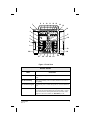
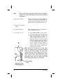
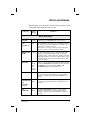
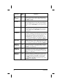
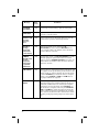
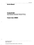
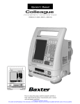
Operator's Manual
Flo-Gard® 6301
Dual Channel Volumetric
Infusion Pump
Table of Contents
Introduction.............................................................................................. 1
Physical Description ............................................................................... 3
Operating Instructions .......................................................................... 10
Precautions ...................................................................................... 10
Loading the Pumps ........................................................................... 11
Starting a Primary Infusion ............................................................... 15
Starting a Secondary Infusion........................................................... 18
Using Volume-Time Programming.................................................... 19
Changing the Flow Rate While the Pump Is Running....................... 21
The OPTIONS Key ........................................................................... 22
Using the Programmed Delivery Profile Feature........................ 22
Computer Control ....................................................................... 25
Computer Monitoring.................................................................. 26
Locking the Front Panel .................................................................... 26
Battery Powered Operation .............................................................. 27
FLOW CHECK Information Display .................................................. 27
Cleaning and Storage ........................................................................... 28
Alerts and Alarms ................................................................................. 29
Technical Specifications ...................................................................... 34
Configurable Options............................................................................ 36
Warranty and Service Information ....................................................... 41
Warranty ........................................................................................... 41
Service Information .......................................................................... 42
7-19-B1-564
i
Change record
7-19-01-564
Original issue: 7/92
Rev. A: 9/92
Rev. B: 05/93
Page
Revision
Front cover
i
ii
1–4
5
6–8
9
10–14
15
16–17
18-30
31–32
33
34
35–38
39–42
Back cover
0
B
B
0
A
0
A
B
0
B
0
B
0
A
0
B
B
A zero in the “Revision” column indicates original issue.
ii
7-19-B1-564
Introduction
The Flo-Gard® 6301 Dual Channel Volumetric Infusion
Pump from Baxter can deliver a wide variety of fluids over
a broad range of infusion rates. The device's features include:
7-19-B1-564
•
Uses only standard Baxter® solution administration
sets.
•
Two separate pump channels allow it to do the work
of two conventional pumps, resulting in space savings.
•
Configurable settings allow the device to be customtailored to best suit the hospital's needs.
•
Computer control capability allows remote control
or monitoring of the device via a standard RS-232C
interface.
•
Infuses a wide variety of fluids, including blood and
fat emulsions.
•
Suitable for use in epidural administration.
•
Safety clamp automatically occludes the tubing
when the pump door is opened.
•
Occlusion sensors detect both upstream and downstream restrictions. Sensitivity of the downstream
occlusion sensor is selectable through the device's
configuration.
•
Flow check display shows resistance to flow.
•
Ultrasonic air-in-line detectors. Sensitivity of the
air detectors is selectable through the device's configuration.
•
Each pump channel features a Programmed Delivery Profile that enables programming of up to 10 sequential infusion programs for situations where
ramping of medications are indicated.
1
2
•
Slide clamp loading option provides flow shut-off
when I.V. set is removed from the pump.
•
Locking control panel helps prevent patient tampering.
•
Each pump channel features an independent secondary medication program. The channel automatically switches over to the primary program upon
completion.
•
Volume-Time programming automatically calculates flow rate.
•
Automatic self-test routine checks for proper function before use.
•
Five-hour memory retains infusion data after
power-off.
•
Easily replaceable fuse, battery, and power cord.
•
Access to test points and internal program simplifies servicing and software upgrades.
•
Device can be configured to display a hospital area
designator, such as “ONCOLOGY” or “CARDIAC
ICU,” upon power-up.
7-19-B1-564
Physical Description
Items 1 through 9 are associated with Pump 1 and are described below. The controls associated with Pump 2 are
identical and function in exactly the same manner. Items 10
through 28 are common to the operation of both pumps. All
front panel items are shown in Figure 1.
Front Panel
ITEM
FUNCTION
1. Pump 1 ONOFF/CHARGE key
Turns Pump 1 on and off. The internal battery charger remains on regardless of the ON-OFF/CHARGE key as long as
the device is plugged in.
2. Pump 1 door
latch
Opens and closes pump door for I.V. set loading and removal.
3. Pump 1 STOP key
Stops Pump 1 until further instructions are given. The message STOPPED appears when the key is pressed. An alert
sounds if Pump 1 is stopped for more than two minutes.
Clears all programming alerts while pump is running.
4. PUMP 1 key and
indicator
Allows keypad and other controls common to both pumps to
accept data for Pump 1 programming. Yellow LED lights to indicate that Pump 1 is selected.
5. Pump 1 main display
Shows rate, volume to be infused (VTBI), and total volume infused for Pump 1 primary and secondary infusion programs.
The decimal point is displayed as an underscore (example:
99_9).
6. Pump 1 message
display
Shows all Pump 1 messages and messages that apply to the
device as a whole.
7. Pump 1 ALARM
LED
Red LED that blinks on and off during a Pump 1 or general
alarm, accompanied by a message display and a repeated sequence of three tones. An alarm indicates that Pump 1 or the
device as a whole requires immediate attention.
8. Pump 1 PUMPING
LED
Green LED which is constantly lit while Pump 1 is pumping.
9. Pump 1 ALERT
LED
Yellow LED which lights during Pump 1 and general alerts,
accompanied by a message display and a repeated single tone.
An alert indicates that Pump 1 or the device as a whole needs
timely attention.
7-19-B1-564
3
Front Panel
4
ITEM
FUNCTION
10. BACK LIGHT key
Backlights the displays when pressed. Pressing the key again
turns the backlight off. If the device is operating on battery
power, the backlight remains on for 60 seconds when the
BACK LIGHT key is pressed.
11. SILENCE key
Temporarily silences an audible alarm or alert for two minutes, unless another alarm or alert occurs on either pump
within the two-minute silence period. All messages remain
displayed.
12. NEXT legend
Lights when theTOT VOL STATUS key is functioning as the
NEXT key.
13. TOT VOL/STATUS
key
Displays total volume delivered for each pump. The key is also
used to advance to the next step when programming a delivery
profile. (See NEXT legend, item 12 above.)
14. CLEAR TOT VOL
key
Resets the total volume delivered by the selected pump to zero
if pressed when the pump is stopped.
15. TIME key
Enters the time over which an infusion is to take place during
Volume-Time programming.
16. PRI RATE key
Allows programming of the primary infusion rate for the selected pump.
17. PRI VTBI key
Allows programming of the primary VTBI for the selected
pump.
18. PRI START key
Starts the primary infusion for the selected pump.
19. Plug icon
Always lit while the device is plugged in and the battery is
charging.
20. MONITOR legend
Lights when the device is being queried by the computer during computer monitoring.
21. Battery icon
Lights when the device is operating on battery power.
22. COMPUTER CONTROL legend
Lights when the device is being controlled by a remote computer.
23. CLR key
Clears any programming values currently being entered.
24. SEC START key
Starts the delivery of the secondary infusion for the selected
pump.
7-19-B1-564
8
7
11 12 13
9 10
14
15
6
16
5
BACK
LIGHT
ALARM
PUMPING
SILENCE
ALERT
ALERT
PUMPING
17
ALARM
NEXT
4
TOT VOL
STATUS
CLEAR
TOT VOL
3
18
TIME
2
PU MP
PUMP
1
P
U
S
H
STOP
1
PRI
RATE
PRI
VTBI
PRI
START
7
8
5
9
6
4
ON
OFF
CHARGE
1
2
3
.
0
CLR
SEC
VTBI
SEC
START
2
P
U
S
H
STOP
ON
OFF
CHARGE
19
OPTIONS
SEC
RATE
COMPUTER
CONTROL
®
28
Flo-Gard® 6301
27
26
25
MONITOR
20
DUAL CHANNEL VOLUMETRIC INFUSION PUMP
24
23
22
21
Figure 1. Front View
Front Panel
ITEM
FUNCTION
25. SEC VTBI key
Allows programming of the secondary VTBI for the selected
pump.
26. SEC RATE key
Allows programming of the secondary infusion rate for the selected pump.
27. Numerical keypad
Programming values and decimal point are entered with these
keys.
28. OPTIONS key
Allows the device to enter an enabled optional mode. These
may include the Programmed Delivery Profile (PDP) or Computer Control modes. If Programmed Delivery Profile and/or
Computer control is available, the OPTIONS key is lit.
7-19-B1-564
Rev. A
5
Figure 2 shows Pump 2 only. Pump 1 has identical features,
which function in the same manner.
Pump Head Features
ITEM
6
FUNCTION
1. Upstream occlusion sensor
Detects a tubing restriction upstream of the
pump.
2. Pumping fingers
The linear peristaltic pump mechanism consists
of cam-driven pumping fingers which successively manipulate the tubing against the backplate, resulting in fluid movement in a
downward direction.
3. Downstream occlusion
sensor
Detects tubing restrictions downstream of the
pump. The sensitivity level can be adjusted to
suit the needs of the hospital through the device's configuration.
4. Air sensor
Detects air bubbles in the tubing. The sensitivity
is adjustable via the device's configuration.
5. Safety clamp
Prevents accidental fluid flow by automatically
occluding the tubing whenever the pump door is
opened.
6. Slide clamp slot
The slide clamp loading option is selectable
through the configuration. When the slide clamp
loading option is enabled, the I.V. set's slide
clamp must be inserted into this slot. The operator must push the slide clamp into the slot to occlude the tubing before the I.V. set can be
removed from the pump.
7. Slide clamp spring retainer
If your hospital has not selected the slide clamp
loading option, this spring retainer is inserted
into the slide clamp slot, preventing the insertion
of the slide clamp.
7-19-B1-564
1
2
3
4
5
6
7
Figure 2. Pump 2 With Door Open
7-19-B1-564
7
The following items are located on the rear of the device
and are shown in Figure 3.
Rear Panel Features
ITEM
8
FUNCTION
1. I.V. pole clamp
Secures the device to the I.V. pole.
2. Power cord strap
Stores the power cord.
3. Audio speakers
For generation of alarm and alert tones.
4. Battery compartment
Allows easy access to the battery. (For use by
authorized service personnel only.)
5. Fuse
Fuse compartment is located behind the power
cord cover.
6. Power cord
Supplies AC power when plugged into a
hospital-grade earth-grounded outlet. Removable by authorized service personel only.
7. PANEL LOCK switch
Disables all front panel keys except BACK
LIGHT and TOT VOL/STATUS when pressed.
8. COMMUNICATIONS PORT
Standard RS-232C port that allows the device to
communicate with a computer and provides the
nurse call signal when enabled.
9. VOLUME knob
Adjusts volume of alert and alarm tones. The
tones cannot be turned completely off.
7-19-B1-564
2
3
1
9
COMMUNICATIONS
PORT
VOLUME
8
PANEL LOCK
(PUSH)
7
5
4
6
Figure 3. Rear View
7-19-B1-564
Rev. A
9
Operating Instructions
Precautions
General
10
•
DANGER—Possible explosion hazard if used
in the presence of flammable anesthetics.
•
Operate device from 115 V, 60 Hz, hospital-grade
earth-grounded outlet only.
•
Though the factory-supplied configuration settings
are suitable for most therapies, the operator and
hospital professionals should verify that the device's
settings are appropriate for their clinical applications.
•
Use only with standard Baxter® soft tubing administration sets with an “s” designation.
•
Read and understand this manual before using this
device.
•
When infusing fluid through a central line catheter,
Baxter recommends that sets with a Luer lock
adapter be used.
•
If using a filter set, use only filters which are suitable for use with infusion pumps. Read and follow
instructions of the filter to be used.
•
To use the automatic piggyback function, use only
Continu-Flo® sets from Baxter as the primary line
with a compatible secondary set for the secondary
line.
•
As with all medical electronic equipment, care must
be exercised to avoid exposing this device to powerful sources of electromagnetic interference. This device design has been tested to the requirements of
7-19-B1-564
MDS–201–004,
and
applicable
portions
of
MIL–STD–461C, which are voluntary test guidelines for electromagnetic susceptibility and emissions. This device was not found to be adversely
affected by the susceptibility tests in these specifications, and will perform safely. The device's emissions were also found to be acceptable.
Epidural Administration
• Epidural administration of anesthetics is limited to
short-term infusion (not to exceed 96 hours) with indwelling catheters specifically indicated for shortterm anesthetic epidural drug delivery.
•
Epidural administration of analgesics is limited to
use with indwelling catheters specifically indicated
for either short-term or long-term analgesic
epidural drug delivery.
•
To prevent infusion of drugs that are not indicated
for epidural use, do not use administration sets that
incorporate injection sites during epidural delivery.
•
It is strongly recommended that pumps used for
epidural drug delivery be clearly differentiated from
pumps used for other routes of administration.
•
WARNING—Epidural administration of drugs
other than those indicated for epidural use
could result in serious injury to the patient.
Loading the Pumps
1. Plug the device in.
Plug power cord into a 115 V, 60 Hz
grounded outlet, unless temporary battery power is required. The plug icon
lights whenever the device is plugged in.
When the device is not plugged in and is
on battery power, the battery icon lights.
7-19-B1-564
11
Note:
The procedure for preparing and loading the administration set (steps 2 through 9) is the same for Pump 1
and Pump 2.
2. Prepare solution.
Prepare fluid container and administration set according to the directions accompanying the products. Prime the set.
Ensure all air is expelled from the set.
3. Close set regulating
clamp.
4. Open pump door.
Raise pump door latch to horizontal position and pull door open.
5. Load the I.V. set.
a. Press SAFETY CLAMP to open position.
b. If your hospital has enabled the
slide clamp loading feature, insert the slide clamp on the I.V. set
fully into the slot, so that it is flush
with the pump housing. (See Figure
4.) If the slide clamp loading feature
is not enabled, a black spring retainer occupies the slide clamp slot
and the slide clamp cannot be inserted. Proceed to step c.
Note: During an emergency, in the alert
mode, the pump can be operated without
inserting the slide clamp. An alert tone
sounds until the slide clamp is inserted or
SILENCE is pressed. In the alarm mode (software versions later than 1.08), the pump
will NOT start and an alarm tone will
sound if the slide clamp is not loaded.
Figure 4. I.V. Set
Loading Diagram
12
Slide clamp
in slot
7-19-B1-564
c. Load the tubing through the guide
channel from bottom to top as shown
in Figure 4.
d. Ensure that the I.V. tubing is loaded
straight through the pump mechanism tubing guides and safety
clamp.
e. Ensure that the tubing is touching
the pumping fingers before closing
the pump door.
6. Close pump door.
If resistance is felt when closing the
door, check for a misloaded I.V. set.
7. Open set regulating
clamp completely.
a. Verify that no drops are falling in
drip chamber. If flow is observed,
close regulating clamp, recheck I.V.
set loading, and verify that the
proper administration set is being
used.
b. If flow is again observed, do not use
the pump. Have it inspected by service personnel.
Note:
Always close the administration set regulating
clamp(s) before opening pump door and removing set.
8. Attach set to I.V. access
site.
9. Turn pump(s) on by
pressing appropriate
ON/OFF CHARGE key(s).
Verify that the following
self-test occurs when you
turn on the first pump:
a. All segments of the Pump 1 and
Pump 2 message displays appear
momentarily. All segments of the
main display of the powered-on
pump appear momentarily.
b. Three separate audible tones sound.
7-19-B1-564
13
c. If a Hospital Area Designator (HAD)
has been programmed into the device, it is displayed for three seconds
in the Pump 1 message display.
d. The occlusion detection level is momentarily displayed in the Pump 1
message display (LEVEL 1, 2, or 3),
followed by AUDIBLE SWITCHOVER
if the Audible Switchover option is
enabled.
e. If Auto Restart and Flow Check are
both enabled, AUTO RESTART appears for one second in the Pump 1
message display.
f.
If the device is plugged into an AC
outlet, the plug icon is lit. If the device is operating on battery power,
the battery icon is lit.
g. If the message INSERT SLIDE
CLAMP appears when you close the
door, the slide clamp loading option is
enabled. Close the I.V. set's regulating clamp, open the door, and insert
the I.V. set's compatible slide clamp
fully into the slide clamp slot located
below the safety clamp. Close the door
and open the regulating clamp.
10. Set VOLUME knob on the
rear of the device to the
desired level.
14
7-19-B1-564
Starting a Primary Infusion
Note:
The procedures for programming Pump 1 and Pump 2
are identical.
1. Select the pump you
wish to program.
Press PUMP 1 or PUMP 2 as appropriate.
The yellow LED on the PUMP key lights
to indicate that the pump is selected.
2. Set primary flow rate.
a. Press PRI RATE.
b. Program desired flow rate (in
mL/hr) on keypad. Zero cannot be
entered as the first digit.
c. A selected flow rate higher than the
allowable maximum results in the
message Hi appearing in the PRI
RATE display. To correct a mistake,
press CLR or PRI RATE again and reenter correct rate. The flow rate is
displayed in the main display of the
selected pump.
3. Set primary volume to
be infused.
a. Press PRI VTBI.
b. Program desired VTBI (in mL) on
keypad. Set VTBI equal to the
amount of fluid in the container or
less if desired.
c. To correct a mistake, press CLR or
PRI VTBI again and re-enter the correct VTBI. The VTBI is displayed in
the main display of the selected
pump.
4. Review infusion settings
and/or read total volume
infused.
7-19-B1-564
Press TOT VOL/STATUS key. VOLUME INFUSED is displayed first, followed by
RATE and VTBI.
15
5. If necessary, reset the
volume previously infused on the selected
pump to zero.
Note:
Press the CLEAR TOT VOL key.
Always verify programmed information prior to starting the selected pump.
6. Start the pump.
a. Press PRI START. The green PUMPING LED lights and a moving bar
appears next to the appropriate flow
rate setting.
b. If the alarm (software versions later
than 1.08) or the alert tone sounds
with the message INSERT SLIDE
CLAMP when you press PRI START,
the slide clamp loading option is enabled and the slide clamp has not
been loaded into the slide clamp slot.
Close the I.V. set's regulating clamp,
open the door, and insert the I.V.
set's slide clamp into the slide clamp
slot located below the safety clamp.
Close the door, then open the regulating clamp.
c. Confirm flow by checking for drops
in the I.V. set drip chamber.
d. If Auto Restart is enabled and Flow
Check is not enabled, AUTO RESTART is displayed in the Pump 1
message display.
e. If you wish to program the other
pump, press its ON-OFF/CHARGE key
and repeat steps 1 through 6.
7. To stop an infusion before it is complete:
16
a. Press the appropriate STOP key.
7-19-B1-564
b. The selected pump's PUMPING LED
goes out and STOPPED appears in
the message display.
c. If the pump is not restarted or powered off within two minutes, an
audible alert sounds.
8. To restart an infusion:
a. Press the PUMP 1 or PUMP 2 key as appropriate.
b. Press the appropriate START key.
9. When the infusion completes:
When a pump has delivered the selected
volume, it sounds an alert tone and
switches to a KVO (Keep Vein Open)
rate of 5 mL/hr or the current rate setting, whichever is lower.
10. Remove set(s) from
pump(s) as follows:
a. Press the appropriate STOP key.
b. Close administration set regulating
clamp.
c. Open appropriate pump door.
d. If the slide clamp loading option is
enabled, press the slide clamp fully
into its slot.
e. Press the
position.
f.
SAFETY CLAMP
to the open
Check that no fluid is flowing in set,
then remove set from pump.
g. To turn a pump off, press the appropriate ON-OFF/CHARGE key.
7-19-B1-564
17
Starting a Secondary Infusion
Note:
The procedures for programming a secondary infusion are identical for Pump 1 and Pump 2.
1. Prepare secondary fluid
container and administration set.
a. To perform automatic piggybacking,
a Continu-Flo® set from Baxter
must be used as the primary set.
b. Follow directions accompanying the
products.
c. Ensure all air is expelled from the
secondary set.
2. Attach the secondary set
to the injection site of
the primary set above
the device.
3. Lower primary container
with the hanger accompanying the secondary
set.
4. Set secondary flow rate.
a. Press PUMP 1 or PUMP 2 as appropriate to select the desired pump.
b. Press SEC RATE key. The right-hand
side of the selected pump's main display now shows secondary infusion
data.
c. Enter desired flow rate (in mL/hr)
for the secondary solution.
d. To correct a mistake, press CLR or
SEC RATE again and re-enter the correct value.
5. Set secondary volume to
be infused.
18
a. Press the SEC VTBI key.
7-19-B1-564
b. Enter the desired fluid amount (in
mL) on the keypad. Set VTBI equal
to the volume of fluid in the container.
c. To correct a mistake, press CLR or
SEC VTBI again and re-enter the correct value.
6. Open secondary set
regulating clamp.
Check also that the primary set regulating clamp is open.
7. Press SEC START to begin
the infusion.
a. Verify that drops begin falling in the
secondary set drip chamber only.
b. Verify that the secondary program is
displayed.
c. When the VTBI of the secondary
program reaches zero, the pump will
revert to the primary program.
When this happens, if the primary
flow rate is set above 999 mL/hr, be
sure to close the secondary set
regulating clamp.
Using Volume-Time Programming
Volume-Time Programming allows you to select a VTBI and
the amount of time over which the infusion is to take place.
The device automatically calculates the required flow rate.
If the calculated rate is outside of the device's capabilities,
the message Hi or Lo appears as appropriate. Volume-Time
Programming can be used for primary and secondary infusions. In the procedure below, the keys to press for secondary programming are shown in parentheses.
Note:
7-19-B1-564
The Volume-Time Programming procedures are identical for Pump 1 and Pump 2.
19
1. Turn on and select the
pump.
a. Press the appropriate ON-OFF/CHARGE
key.
b. Press PUMP 1 or PUMP 2 as appropriate to select the desired pump.
2. Enter a VTBI.
a. Press the PRI VTBI key (or SEC VTBI, if
you are programming a secondary
infusion).
b. Program the desired VTBI on the
keypad.
c. To correct a mistake, press the CLR
key and re-enter the correct VTBI.
3. Enter a time.
a. Press the TIME key. Enter the
amount of time (up to 99 hours and
99 minutes) over which you wish the
infusion to take place.
b. To correct a mistake, press the CLR
key or TIME key again and re-enter
the correct time.
4. Press the PRI RATE (or
SEC RATE) key.
a. The device calculates the flow rate
required to deliver the desired VTBI
in the specified time period.
b. If the calculated flow rate is higher
than the device's capabilities, the
message Hi is displayed. To correct a
Hi message, repeat the procedure
from step 2 and enter a longer time
period if appropriate.
c. If the calculated rate is too low, the
message Lo is displayed. To correct
a Lo message, repeat the procedure
from step 2 and enter a shorter time
period if appropriate.
20
7-19-B1-564
5. Check the rate, then
start the pump.
Verify that the calculated rate is acceptable before pressing PRI START (or SEC
START) to begin the infusion.
Changing the Flow Rate While the Pump Is Running
To change the primary or secondary flow rate during the
course of an infusion, follow the procedure given below. The
keys to press for a secondary infusion are shown in parentheses.
1. Select the pump.
Press PUMP 1 or PUMP 2 as appropriate to
select the desired pump.
2. Press PRI RATE (or SEC
RATE) while pump is running.
NEW RATE appears in the selected
pump's message display and an alert
tone sounds periodically.
3. Enter the new flow rate
on the keypad.
a. If the primary rate is changed above
999 mL/hr, ensure that the secondary set regulating clamp is closed.
b. If a new rate higher than the allowable maximum is entered, Hi
appears in the appropriate rate display.
4. Press PRI START (or SEC
START).
7-19-B1-564
The pump begins delivering fluid at the
new rate, the alert tone stops, and the
NEW RATE message disappears.
21
The OPTIONS Key
The OPTIONS key is used to place the device into Computer
Control mode and to set a Programmed Delivery Profile
(PDP). The OPTIONS key is active only when at least one of
these two features has been made available in the device's
configuration. Pressing the OPTIONS key with neither pump
selected selects Computer Control (if enabled). Selecting a
pump and then pressing OPTIONS puts the pump into PDP
mode (if enabled). The PDP mode allows you to program an
infusion with up to 10 different steps.
NOTE:
If the word OPTIONS is not visible when a pump is powered on, you cannot use computer control or PDP.
Consult qualified hospital biomedical personnel regarding the appropriateness of the device's settings.
Using the Programmed Delivery Profile Feature
Each pump channel has a Programmed Delivery Profile
(PDP) that allows you to program an infusion which
changes over time. This feature, which can be made available through the device's configuration, lets you program an
infusion of up to 10 different steps. The pump automatically
changes to the next programmed rate once the VTBI of a
step has been delivered. To use a PDP:
1. Verify that the OPTIONS
key is lit.
If OPTIONS is not lit, your device is not
configured for PDP. Consult with
authorized hospital personnel if you
have questions regarding the appropriateness of your device's configuration
settings.
2. Select a pump.
Press PUMP 1 or PUMP 2 as appropriate.
The yellow LED on the PUMP key lights
to indicate that the pump is selected.
22
7-19-B1-564
3. Place the pump into
PDP mode by pressing
the OPTIONS key.
The message PGM DELIV appears and
the NEXT legend over the TOT VOL/STATUS
key lights. The pump is now in PDP
mode.
4. Review previous PDP
settings.
a. If a previously set PDP is stored in
the pump's memory, STEP 1 appears in the message display and
the rate and VTBI of the first programmed step appear in the main
display.
b. If you wish to clear the stored PDP,
press the CLR key. The message
CLEAR ALL? appears. Press the CLR
key again to actually clear the PDP.
The CLEAR ALL? message disappears.
c. If you wish to use the stored PDP,
continue pressing the NEXT key to
scroll through all steps of the PDP
until the first step is again displayed. Review each step to ensure
that the PDP is appropriate.
d. To begin the PDP, press PRI START.
The message REVIEW PDP appears
if you have not completed reviewing
the stored PDP. After you have reviewed all steps and pressed PRI
START, the pump begins delivering
fluid.
Note:
If you enter PDP mode and then try to start the pump
without first entering a PDP, the message ENTER PGM
appears on the second line of the message display. The
message disappears once you start to enter a PDP.
5. Modify previous PDP
settings.
7-19-B1-564
a. After completing steps 1 through 3
above, press the NEXT key to reach
the PDP step you wish to modify.
23
b. Press the key for the infusion parameter you wish to modify (PRI VTBI
or PRI RATE).
c. Enter the new value on the keypad.
d. Press the
value.
NEXT
key to enter the new
e. Modify additional PDP steps if desired. After reviewing or changing
the last step, press NEXT again, until
the first step is displayed.
f.
6. To program a new PDP:
24
To begin the PDP, press PRI START.
The pump begins delivering fluid.
a. After completing steps 1 through 3
above, enter the desired values using one of the following methods:
•
Entering rate and VTBI—Use
PRI RATE, PRI VTBI and the numeric keypad exactly as if programming a primary infusion.
You may enter rate and volume
in either order.
•
Entering
VTBI
and
time—First press PRI VTBI and
enter a value. Then press TIME
and enter a time span for this
step (up to 99 hours and 99 minutes). Finally, press PRI RATE.
The device calculates and displays the resulting flow rate. If
the display reads Hi or Lo, the
calculated rate is outside the device's capabilities. Re-enter the
VTBI and the time and press PRI
RATE again.
•
Entering rate and time—First
press PRI RATE and enter a value.
7-19-B1-564
Then press TIME and enter a time
span for this step (up to 99
hours and 99 minutes). Finally,
press PRI VTBI. The device calculates and displays the resulting
volume. If the display reads Hi
or Lo, the calculated VTBI is
outside the device's capabilities.
Re-enter the rate and the time
and press PRI VTBI again.
b. Press the NEXT key to lock in the programmed values and advance to the
next step.
c. Program all remaining steps (up to
10) in the same manner. After entering settings for the last step, press
NEXT again, until the first step is displayed.
d. To begin the PDP, press PRI START.
The pump begins delivering fluid.
To pause during a PDP, press the pump's STOP key. To resume from the point at which you left off, select the pump
(with PUMP 1 or PUMP2) and press PRI START.
To drop out of PDP, select the pump and then press
TIONS, PRI RATE, SEC RATE, or SEC VTBI.
OP-
In PDP mode, the pump switches to the KVO rate when it
reaches a step that has a rate and VTBI of zero or when it
finishes the tenth step.
Computer Control
The Computer Control option allows the device to be controlled by a remote computer. Computer Control is an option made available through the configuration.
When the device is under computer control, the COMPUTER CONTROL legend on the front panel is lit.
7-19-B1-564
25
Pressing any enabled key (other than SILENCE, TOT
VOL/STATUS, BACK LIGHT, PANEL LOCK, or the key combination
for the Flow Check display or the Alarm Log display) causes
the device to drop out of computer control, allowing you to
clear alarms and/or change infusion data.
Computer Monitoring
When the device is set up for computer monitoring, information is gathered by a remote computer via the COMMUNICATIONS PORT. The computer connected to the device does
not control it; it simply monitors infusion data. The MONITOR legend on the front panel lights whenever the computer queries the device for information. The device is
operated in exactly the same manner as if it were not connected to the computer.
Locking the Front Panel
The front panel keys can be locked during pumping to prevent tampering. They can be unlocked at any time. The TOT
VOL/STATUS and BACK LIGHT keys are not affected by the lockout. This allows routine infusion data checks while the front
panel is still locked. If either pump is stopped due to an infusion alarm or an opened door, the panel must be unlocked
to restart the infusion.
1. To lock the panel:
With all powered-on pumps running,
press the PANEL LOCK switch on the rear
of the device for at least one second. The
message Loc appears in the main display of pumps that are powered on.
2. To unlock the panel:
Press the PANEL LOCK switch again. The
Loc message disappears.
26
7-19-B1-564
Battery Powered Operation
The device automatically switches to battery operation
when the AC power is interrupted or the device is unplugged. When operating on battery power, the battery icon
on the front panel is lit. The battery automatically recharges whenever the device is plugged in. It is recommended that the device be plugged into an AC outlet during
storage to help maintain batteries at full charge.
FLOW CHECK Information Display
The Flow Check feature displays the resistance to flow.
There is a separate display for each pump. As shown in Figure 5, the FLOW CHECK display is a dashed line that
stretches from left to right as the resistance to flow increases. The left side of the display is labeled norm and corresponds to the pressure when the infusion was initially
started or manually restarted after an alarm. The right side
of the display is labeled occ and corresponds to the next occlusion threshold. Selecting the Flow Check option in the
configuration results in the FLOW CHECK display appearing whenever the pump is running. Whether or not the
Flow Check option is selected, the display may be momentarily viewed whenever the front panel is unlocked by
pressing the decimal point and TOT VOL/STATUS simultaneously.
Figure 5. Flow Check Display
7-19-B1-564
27
Cleaning and Storage
The exterior of the device may be cleaned with a soft cloth,
sparingly dampened with any of the cleaners listed below.
Follow manufacturers' dilution instructions for concentrated cleaners. Used devices should be cleaned/disinfected
with an agent from the list below before use on another patient. If spillage into either pump mechanism occurs, clean
the mechanism immediately by wiping with a soft cloth
dampened with any of the cleaners listed below.
Cleaner
Manufacturer
LpH, Septisol
Vestal Labs
Cidex 7
Surgikos
Super Edisonite
Edison Chemical Co.
TOR, Hi-Tor Plus
Huntington Labs
Bafix
Hysan Corp.
A solution of 10% bleach and water
Soapy water
Isopropyl alcohol up to 95%
Note:
Do not clean, disinfect, or sterilize any part of the device by autoclaving or with ethylene oxide gas. Doing
so may damage the device and void the warranty.
Do not use the following chemicals on the device, as
they will damage the front panel: acetone, ammonia,
benzene, hydroxytoluene, methylene chloride, n-alkyl
dimethyl ethylbenzyl ammonium chloride, and ozone.
It is recommended that the pump be plugged in during storage to help maintain the batteries at full charge. Do not
store the device with either ON-OFF/CHARGE key ON. The
battery may discharge completely.
28
7-19-B1-564
Alerts and Alarms
The following chart describes alarm and alert messages for
each pump along with the cause of each.
Message
Flow
Status
Condition
Alert Messages
STOPPED
No flow
Pump has been in STOPPED mode for two minutes.
KVO
PRI VTBI = 0
KVO
Primary VTBI has been delivered or the PDP has finished.
The pump has switched to a KVO rate of 5 mL/hr or programmed rate, whichever is less.
This alert also occurs if you start the pump without first
entering a non-zero value for the primary VTBI.
INSERT SLIDE
CLAMP
No effect
The slide clamp loading option is enabled and the slide
clamp is not loaded into the slide clamp slot. Close the
regulating clamp, open the pump door, and insert the slide
clamp fully into the slot, so that it is flush with the pump
housing. Close the door, open the regulating clamp, and
restart the pump.
NEW RATE
No
change
until
procedure is
complete
Flow rate is being changed while pump is running. Pump
remains in NEW RATE alert condition until the appropriate START key is pressed. Pressing STOP or TOT
VOL/STATUS displays the current flow rate.
PRI RATE = 0
No flow
A primary flow rate of zero has been entered. The pump
remains in this alert condition until a non-zero primary
flow rate is entered and the appropriate START key is
pressed.
BATTERY LOW
No
change
Battery needs recharging. Pump will stop operating in approximately fifteen minutes unless it is plugged into an
AC outlet.
No
change
The SEC COMPLETE alert option is enabled and the
pump has completed its secondary program and has
switched to primary. Press any enabled key to exit from
this alert.
with
intermittent
alert tone
SEC
COMPLETE
7-19-B1-564
29
Message
Flow
Status
Condition
SEC
PROGRAM
No
change
Secondary program data is being entered while pump is
running. Pump remains in alert condition until you press
SEC START or STOP.
SEC RATE = 0
No flow
An attempt has been made to start the secondary program
with a secondary flow rate of zero. The pump remains in
this alert condition until you enter a non-zero secondary
flow rate and press SEC START, or start the primary program.
SEC VTBI = 0
No flow
A secondary VTBI of zero has been entered. The pump remains in this alert condition until you enter a non-zero
secondary VTBI and press SEC START, or start the primary program.
FLOW RATE
No flow
During Volume-Time Programming, if a flow rate outside
the pump's capabilities is calculated, the message Hi or Lo
appears in the rate display. If an attempt is made to start
the pump with either of these messages displayed, a
FLOW RATE alert is triggered. To exit this alert condition, reprogram the pump for a rate within the range set
in the configuration and press the appropriate START key.
CHECK VTBI
No flow
A VTBI outside the acceptable range has been entered. To
exit this alert condition, enter a VTBI within the range set
in the configuration and press the appropriate START key.
PGM DELIV
ENTER PGM
No flow
The pump is waiting for a Programmed Delivery Profile.
Either enter the profile (as described on p. 24), or press
OPTIONS to leave PDP mode.
PGM DELIV
REVIEW PGM
No flow
An attempt has been made to start a Programmed Delivery Profile before reviewing all the steps. Either press
NEXT until the first step is again displayed, or press OPTIONS to leave PDP mode.
PGM DELIV
CLEAR ALL?
No flow
The pump is asking for confirmation that all steps of the
existing Programmed Delivery Profile should be erased.
Do one of the following: press CLR to erase the profile;
press NEXT to begin reviewing the rest of the profile;
press PRI RATE or PRI VTBI to modify this step; or press
OPTIONS to leave PDP mode.
30
7-19-B1-564
Message
Flow
Status
Condition
COM TIMEOUT
No
change
There has been no communication between the device and
the computer for the specified time period. Check for a disconnected cable or computer problem. To clear this alert,
press the OPTIONS key to return the device to computer
control, or press SILENCE or PUMP 1 or PUMP 2 to use
the pump(s) without the computer.
EXT COMM
ERROR
No
change
The controlling or monitoring computer is sending multiple questions or instructions to the device without waiting
for the device's replies. The condition has been caused by
the computer, not the device. To clear the alert, press OPTIONS to return the device to computer control (if appropriate), or press SILENCE or PUMP 1 or PUMP 2 to control
the pump(s) manually. Notify the technical personnel responsible for the computer. If the alert recurs, disconnect
the cable from the communications port. Reprogram the
pump(s) for manual operation.
Alarm Messages
CHECK SET
LOADING
No flow
I.V. set is not loaded properly. Close the regulating clamp,
open the pump door, and verify that the set is loaded properly against the pumping fingers and through the upstream and downstream occlusion sensors. Close the door,
open the regulating clamp, and restart the pump.
AIR
No flow
a. Air bubble at detector
b. Empty fluid container
c. No I.V. set in pump
OCCLUSION
No flow
Closed distal clamp, stopcock, clogged filter or other blockage downstream of the pump.
Note: The pump can be set up to restart itself automatically when the occlusion is removed. If you want to
prevent the pump from restarting automatically, press
any enabled key (such as SILENCE) during the alarm.
INSERT SLIDE
CLAMP
Note: This
alarm option is
available only
on pumps
running
software
versions later
than 1.08.
No flow
The slide clamp loading option is enabled and the slide
clamp is not loaded in the slide clamp slot. To clear this
alarm, open the pump door and insert the slide clamp into
the slot. Close the door.
7-19-B1-564
31
Message
Flow
Status
UPSTREAM
OCCLUSION
No flow
Closed clamp or other blockage upstream of the pump.
DOOR OPEN
No flow
Pump door not fully closed. The door latch must be fully
lowered to a vertical position.
BATTERY LOW
with rapid
three-tone
alarm
No flow
Battery power has been exhausted. Plug device into AC
outlet to restore operation and recharge battery.
FAILURE in
message
display with
code number
in main display
No flow
Pump-specific failure. Press appropriate ONOFF/CHARGE key twice to reset. If FAILURE does not
clear, record the failure code number, remove the device
from use and have it serviced.
COMMON
FAILURE in left
message
display and
code number
in right SEC
VTBI display
No flow
General failure. Press each ON-OFF/CHARGE key in turn
until both pumps are powered off. Power one or both
pumps on again. If COMMON FAILURE does not clear, record the failure code number, remove the device from use,
and have it serviced.
COM TIMEOUT
No flow
There has been no communication between the device and
the computer for the specified time period. Check for a disconnected cable or computer problem. To clear this alarm,
press the OPTIONS key to return the device to computer
control, or press SILENCE or PUMP 1 or PUMP 2 to use
the pump(s) without the computer.
EXT COMM
ERROR
No flow
The controlling computer is sending multiple questions or
instructions to the device without waiting for the device's
replies. The condition has been caused by the computer,
not the device. To clear the alarm, press OPTIONS to return the device to computer control, or press SILENCE or
PUMP 1 or PUMP 2 to control the pump(s) manually. Notify the technical personnel responsible for the computer.
If the alarm recurs, disconnect the cable from the communications port. Reprogram the pump(s) for manual operation.
32
Condition
7-19-B1-564
Note:
7-19-B1-564
The last ten alarm codes are stored in memory for
each pump. You can review these codes when the
pump is powered on and stopped. To recall the stored
alarm codes, press SILENCE and TOT VOL/STATUS simultaneously. The alarm code that occurred most recently
for each powered-on and stopped pump appears in
that pump's message display. To scroll back through
the other stored alarm codes, press CLEAR TOT VOL
within one second. Alarm Recall is exited automatically if the CLEAR TOT VOL key is not pressed within one
second. The alarm codes are date and time stamped.
They are detailed in the Service Manual.
33
Technical Specifications
ITEM
SPECIFICATION
Catalog Code Number
2M8064
Description
Dual Channel Linear Peristaltic Volumetric Infusion Pump
Administration Set
Baxter® “s” designated sets
Keep Vein Open (KVO)
Rate
5 mL/hr or programmed rate, whichever is less
Nurse Call
Available through the COMMUNICATIONS PORT
Battery
12 volt, 3.2 ampere-hour sealed lead-acid
Battery Life
-Approximately 6 hours with one pump running at a rate
from 1 to 1400 mL/hr
-Approximately 4 hours with both pumps running at rates
from 1 to 1400 mL/hr
Battery Recharge
8 hours for more than 80% recharge
AC Power Requirements
110/120 V, 60 Hz
Power Cord
2.9 m (9.5 ft) long, with Hospital Grade plug
Fuse
0.8 A, 250 V, SB, 5.2 mm (13 64 in.) × 20 mm (25 32 in.)
Leakage Current
Less than 50 microamps (using UL-544 specified test methods)
Weight
8.1 kg (17.9 lbs)
Dimensions
33 cm W × 13 cm D × 29 cm H (13" W × 5.1" D × 11.4" H)
Flow Rate Range
Primary program for each pump: 1.0–99.9 mL/hr in 0.1 mL
increments or 1–1999 mL/hr in 1 mL increments. Upper
limit can be reduced by authorized service personnel.
Secondary program: 1.0–99.9 mL/hr in 0.1 mL increments
or 1–999 mL/hr in 1 mL increments, subject to the upper
limit that also applies to the primary program.
VTBI Range
1.0–99.9 mL in 0.1 mL increments or 1–9999 mL for both
primary and secondary of each pump. Upper limit can be
reduced by authorized service personnel.
34
7-19-B1-564
Rev. A
ITEM
Air-in-Line Detection
7-19-B1-564
SPECIFICATION
Factory set to NORM, which causes the device to alarm on
air bubbles approximately 75 µL or larger. The MIN setting
causes the device to alarm on air bubbles approximately 50
µL or larger.
35
Configurable Options
The device has several features which can be selected to
best suit the needs of the hospital. The settings for these
features are referred to as the configuration. The configuration applies to the device as a whole unit, and thus to both
pumping channels.
To see your device's configuration settings:
a. Both pumps must be stopped. Press
TIME and TOT VOL/STATUS simultaneously, and hold for one second. The
message REVIEW CONFIG appears
in the left message display. The first
option and its current setting appear
in the right message display.
b. To view the next option, press the
NEXT or SEC START key.
c. To stop viewing the configuration,
again press TIME and TOT VOL/STATUS
simultaneously.
Note:
If there is any question regarding the device's current
configuration or applicability for a particular clinical application, the operator and hospital professionals should verify that the settings are appropriate.
The configuration can be changed only by designated
personnel.
The following table shows all of the configurable items,
their available settings, and the way they are set when the
device leaves the factory.
36
7-19-B1-564
Configurable Options
Item
Descriptor
Occlusion Alarm Level
(Pressure increments
which trigger an OCCLUSION alarm. This
setting is displayed for
one second after the selftest when the pump is
turned on.)
OCCLUSION
LEVEL n
1 = LEVEL 1
(approximately 7 psig)
2 = LEVEL 2
(approximately 12 psig)
3 = LEVEL 3
(approximately 17 psig)
LEVEL 1
Audible Switchover from
secondary to primary
program. When ON,
AUDIBLE SWITCHOVER
is displayed for 1 second
after the self-test when
the pump is turned on.
AUDIB SWI
1 = OFF
2 = ON
OFF
Number of Automatic Re- AUTO RES
starts
The number of times the
pump will restart automatically after a downstream occlusion occurs
and is then relieved.
When ON, AUTO RESTART is displayed while
the pump is running. If
Flow Check is also enabled, AUTO RESTART is
displayed for one second
after the self-test when
the pump is turned on.
0 to 9
3
Door Open Required
DOOR OPEN
1 = OFF
2 = ON
(door must be opened after a
downstream occlusion alarm.)
OFF
Air Bubble Alarm Size
AIR SIZE
1 = MIN (25–85 µL)
2 = NORM (50–110 µL)
NORM
Alarm Off Interval
ALARM INT
1–7 seconds
1 sec.
Alert Off Interval
ALERT INT
1–7 seconds
7 sec.
7-19-B1-564
Options
Factory
Setting
37
Configurable Options
Item
Descriptor
Options
Factory
Setting
Maximum Flow Rate
MAX RATE
1–1999 mL/hr
1999
mL/hr
Maximum VTBI
MAX VTBI
1–9999 mL
9999 mL
Flow Check Display
FLOW
CHECK
1 = OFF
(The decimal point & TOT
VOL/STATUS keys must be
pressed to view the Flow
Check display)
2 = ON
(Flow Check display visible
whenever pump is running)
OFF
1 = 300
2 = 1200
3 = 2400
4 = 4800
5 = 9600
9600
1 = DISABLED
(computer control not available)
2 = OFF W ALRM (device
drops out of computer control
when an alarm occurs)
3 = ON W ALRM (device remains in computer control
during an alarm)
DISABLED
0 = No message
1 = NICU
2 = PICU
3 = MED/SURGICAL
4 = TRAUMA/BURN UNIT
5 = OPER ROOM
6 = CARDIAC/ICU
7 = SURGICAL/ICU
8 = ICU
9 = ONCOLOGY
No message
BAUD RATE
Baud Rate
(The rate of information
exchange between the device and the computer
when in computer control
or computer monitoring)
Computer Control
(Selects the type of computer control available at
power-up)
COMP CONT
Hospital Area Designator HAD
(displayed for 3 seconds
after self-test. Custom
designators can be created using a computer.)
38
7-19-B1-564
Configurable Options
Item
Descriptor
Close Clamp Message
(CLOSECLAMP appears
with DOOR OPEN message to remind the user
to close the I.V. set regulating clamp when the
pump door is open.)
CLOSE CLMP
Options
Factory
Setting
1 = OFF
2 = ON
ON
Slide Clamp Loading Op- INS CLAMP
tion
Note: The alarm option is
available only on pumps
running software versions later than 1.08.
1 = OFF
2 = ON for software versions
earlier than 1.09, or ALERT
for software versions later
than 1.08 (An audible alert occurs and the message INSERT
SLIDE CLAMP is displayed if
the pump is used without first
loading the set's slide clamp
into the slide clamp slot.)
3=ALARM (An audible alarm
occurs and the message INSERT SLIDE CLAMP is displayed. The pump will not
operate.)
OFF
Programmed Delivery
Profile
PDP
1 = DISABLED (No PDP allowed)
2 = FIVE HOUR (profile can
be entered from front panel
and is saved in 5-hour memory)
3 = SEMI PERM (profile can
be entered from front panel;
pump remembers the most recent profile)
4 = PERM (Profile is saved in
permanent memory. If a new
PDP is entered, the pump will
revert to the PDP in permanent memory after the current
run.)
DISABLED
Time Setting
TIME SET
Real time entered in hours
and minutes
Central
Standard
time
7-19-B1-564
39
Configurable Options
Item
Date Setting
40
Descriptor
DATE SET
Options
Month/Day/Year
Factory
Setting
Current
date for
Central
Standard
Time
7-19-B1-564
Warranty and Service Information
Warranty
Baxter Healthcare Corporation (“Baxter”) warrants that the
equipment shall be free from defects in material and workmanship when delivered to the original purchaser. Baxter's
sole obligation shall be limited to repair or replacement, at
Baxter's option and expense, of the defective part or unit,
excluding batteries, for a period of one year following the
date of initial delivery. The warranty period for batteries is
limited to a period of six months following the date of initial
delivery.
The warranty extends only to the original purchaser and is
not assignable or transferable, and shall not apply to auxiliary equipment or disposable accessories.
THERE ARE NO OTHER WARRANTIES INCLUDING
ANY IMPLIED WARRANTY AND ANY WARRANTY
OF MERCHANTABILITY OR FITNESS FOR A PARTICULAR PURPOSE WHICH EXTEND BEYOND THE
DESCRIPTION OF THE PRODUCT AND THOSE EXPRESSLY SET FORTH IN ITS LABELING. UNLESS
USED ACCORDING TO THE DIRECTIONS ACCOMPANYING THE PRODUCT, ALL WARRANTIES ARE
SPECIFICALLY EXCLUDED. In no event shall Baxter
Healthcare Corporation be responsible for incidental, consequential or exemplary damages. Modification, alteration,
recalibration or abuse, and service by other than a Baxter
Healthcare Corporation authorized representative may void
the warranty.
7-19-B1-564
41
Service Information
While under Baxter Healthcare Corporation Warranty,
Service Agreement (optional), or lease agreement, the instrument must not be opened by unauthorized personnel.
To contact Baxter Healthcare Corporation Customer Service Division for service and repair information for all instruments, call 1-(800) THE PUMP.
Shipping costs for all units returned to Baxter Healthcare
Corporation shall be paid by the customer. The unit must
be packed in its original container or in another Baxter approved container that will provide adequate protection during shipment. To ensure prompt return, a Baxter Product
Service representative must be notified before shipping any
unit for repair. When calling Baxter Product Service, please
be prepared to provide code number and serial number of
the unit. A service request number will be issued and
should accompany all communications. A brief written description of the problem should be attached to the instrument when it is returned for service.
Baxter Healthcare Corporation will not be responsible for
unauthorized returns or for units damaged in shipment due
to improper packing.
42
7-19-B1-564
Baxter Healthcare Corporation
Deerfield, IL 60015 USA
07-19-C1-564
©Copyright 1993, 1999, Baxter Healthcare Corporation. All rights reserved.