1
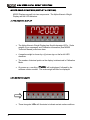
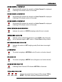
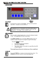
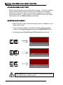
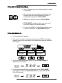
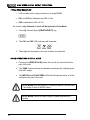
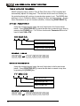
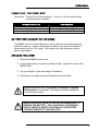
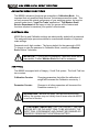
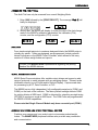
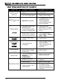
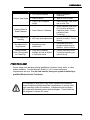
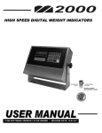
WESTERN SCALE CO. LTD.
HIGH SPEED DIGITAL WEIGHT INDICATORS
* FOR SOFTWARE VERSION 1.45 OR HIGHER. * RELEASE DATE: 12-01-03 *
M2000 DIGITAL WEIGHT INDICATORS
USER MANUAL
Copyright © 2003 Western Scale Co. Limited. All rights reserved.
Published by:
WESTERN SCALE CO. LTD.
1670 Kingsway Ave.
Port Coquitlam, B.C.
Canada
V3C 3Y9
Information in this User Manual is subject to change without notice due to
correction or enhancement. The information described in this manual is the
property of Western Scale Co. Ltd. No part of this manual may be reproduced or
transmitted in any form, without the expressed written permission of Western
Scale Co. Ltd.
WESTERN SCALE LOCATIONS
WESTERN SCALE CO. LTD.
WESCALE INC.
1670 Kingsway Avenue
Port Coquitlam, B.C.
Canada
V3C 3Y9
DIVISION OF WESTERN SCALE
Ph: (604) 941-3474
Fx: (604) 941-4020
3873 Airport Way
Bellingham, WA.
USA
98227 – 9754
www.wescale.com
[email protected]
www.westernscale.com
www.westernscale.ca
[email protected]
FOR TECHNICAL SUPPORT REGARDING THIS PRODUCT, PLEASE CALL
THE WESTERN SCALE SERVICE DEPARTMENT:
(604) 941-3474
[email protected]
FOR MORE INFORMATION, CONTACT [email protected]
TABLE OF CONTENTS
Introduction………………………………………………………………………………….
Note To M2000 Users……………………………………………………………..
M2000 Indicators….………………………………………………………………..
Receiving Inspection……………………………………………………………
M2000 User Interface……………..………………………………………………………
Alpha-Numeric Display …………………………………………………………
LED Indicator Lamps.…………………………….……………………………..
Function Keys……………………………………………………………….……..
ON/OFF key ……………………………………………………………
ZERO SCALE key…………………………………………………….……
CLEAR key………………………………………………….. …………
TARE key ………………………………………………………………..
PRINT/SELECT key……………………………………………………..…
Standard M2000 Functions……………………………………………………………….
Selecting Scale Channels…………………………………………………………..
Total Mode……………………………………………………………..…………
Total Mode Example 1………………………………………………………
Total Mode Example 2……………………………………………………
Scale Operations in Total Mode………………………………………
Scan Mode………………………………………………………………………..
Gross/Net Weighing Modes…………………………………………………..
Selecting lbs / kgs.……………………………………………………………….
Test Display…………………………………………………………………..…..
Time & Date on the M2000…………………………………………………..……………….
Set Time……………………………………………..……………………………..
Example………………………………………………………………….
Set Date…………………………………………………………………………..
Example ………………………………………………….…………..
Time Format………………………………………………..………………….
Battery Replacement on the M2000………………………………….……………..
Replacing the Battery……………………………….……………………..
Advanced M2000 Functions…………………………………………………….………..
Electronic Seal……………………………………………….……………………
Audit Trail…………………………………………………………………….…...
Accessing the Audit Trail………………………………………………
Printing………………………………………………………………………………
Serial Communications……………………………………………………….……
Barcode Scanners & other Peripheral Devices………………………..……………
Industry Specific Programs & Features………………………………………………
M2000 Option Boards……………………………………………………………
Filtering & Adjustments……………………………………………….…………
Entering Setpoint Values…………………………………………………………….
M2000 User Trouble Shooting……………………………………………………………
M2000 Specifications……………………………………………………………………...
2
2
3
3
4
4
4
6
6
6
6
7
7
8
8
9
9
10
10
11
11
11
11
12
12
12
12
12
13
13
13
14
14
14
15
15
15
15
16
16
16
17
18
20
1
HIGH SPEED DIGITAL WEIGHT INDICATORS
INTRODUCTION
Thank you for choosing the smart weighing solution!
Utilizing over 25 years of research and development in electronic weighing
systems, Western Scale’s M2000 high performance scale indicators are the
industry standard for speed, versatility, and reliability.
From Truck In/Out programs to Cattle weighing, the M2000 can be customtailored to meet the needs of all weighing applications. With up to 3 independent
scale channels and a totalizing function, an M2000 can easily take the place of
three other indicating devices. M2000 indicators are easy to use and compatible
with all scale systems, making them ideal for new installations as well as
upgrades to existing systems.
For a complete synopsis of M2000 Indicator functions, information on other
custom weighing services, or additional information about Western Scale, please
visit www.westernscale.com.
* * * NOTE TO M2000 USERS * * *
•
This User Manual is intended for operational use by Western Scale Co.
Ltd. customers. Information regarding standard indicator functionality is
contained within.
•
Due to the important role weighing systems play, certain functions and
features of M2000 indicators should only be accessed by qualified Scale
Technicians. Specific information regarding Communications, Enabling &
Disabling M2000 functions, Scale Set-up, and Scale Calibration can be
found by calling the Western Scale Service Department, (604) 941-3474.
For the best results, have your system installed to your unique
specifications by a qualified Western Scale Technician.
2
USER MANUAL
M2000 INDICATORS
The M2000 Indicator family includes:
•
M2000 A – 3 Channel Analog Indicator (2 COM Ports). One of the
world’s best and most affordable high speed, fully featured indicators.
For use with Analog loadcells.
•
M2000 AS – Single Channel Indicator (1 COM Port). M2000 features
and quality at a low cost. For use with Analog loadcells.
•
M2000 D - 3 Channel Digital Indicator (2 COM Ports). Digital
Communication with your scale for maximum lightning protection and
data integrity. Converts Analog loadcell signals to digital at the scale
via the DLC Smart Box.
M2000 Indicators are available in a variety of enclosures, including
the NEMA rated, wash-down model NSS-1. Call your Western
Scale representative for details.
RECEIVING INSPECTION
It is always good practice to verify that the M2000 Indicator Kit is undamaged
upon receipt.
•
Check over packaging for any signs of damage.
•
Remove the M2000 indicator from its protective packaging and check
for damage.
Each M2000 Indicator Kit should include:
M2000 Indicator
12 Volt Power Supply & Power cord (Slimline models only)
M2000 User Manual
Capacity Label Set
Removable Connectors for all M2000 terminals
Correct number of cable strain-reliefs (For stainless steel enclosure
models)
BE SURE TO CHECK THAT ALL NECESSARY OPTION BOARDS
HAVE BEEN INCLUDED.
3
HIGH SPEED DIGITAL WEIGHT INDICATORS
M2000 USER INTERFACE (DISPLAY & KEYPAD)
M2000 Displays are split into two components: The Alpha-Numeric Weight
Display and the LED indicators.
ALPHA-NUMERIC DISPLAY
[]2000
•
The Alpha-Numeric Weight Display has 6 multi-character LED’s. Scale
weights, Error messages, and Calibration information (See M2000
Technical Manual) are shown here.
•
A negative weight is shown by a (-) minus sign on the far left LED
character.
•
The number of decimal points on the display is determined in Calibration
Mode.
•
On power-up, a scrolling “[]2000” will be displayed, followed by the
software version number. The scale weight will then be displayed.
LED INDICATOR LAMPS
•
4
These triangular LEDs will illuminate to indicate certain scale conditions.
USER MANUAL
SCALE CHANNEL 1 INDICATOR
CH1
Illuminated LED indicates the weight from Scale Channel 1 is displayed.
A blinking LED indicates motion on the scale.
SCALE CHANNEL 2 INDICATOR
CH2
Illuminated LED indicates the weight from Scale Channel 2 is displayed.
A blinking LED indicates motion on the scale.
SCALE CHANNEL 3 INDICATOR
CH3
Illuminated LED indicates the weight from Scale Channel 3 is displayed.
A blinking LED indicates motion on the scale.
GROSS WEIGHING MODE INDICATOR
Indicates the scale is in GROSS weighing mode (No tare is stored).
GR
CENTRE ZERO INDICATOR
0
Indicates scale is within 0.2 graduations of true ZERO. May illuminate
with a displayed weight in NET mode or if Tare Offset is being utilized.
NET WEIGHING MODE INDICATOR
NET
Indicates the scale is in NET weighing mode (Scale has a tare weight
stored).
LB INDICATOR
The scale is weighing in IMPERIAL units (Pounds or a fraction thereof).
lb
KG INDICATOR
The scale is weighing in METRIC units (Kilograms or a fraction thereof).
kg
SCALE MOTION INDICATOR
A blinking Scale Channel LED indicates MOTION on that scale.
CH3
TOTAL MODE INDICATOR
CH1 CH2 CH3
Multiple illuminated Scale Channel LEDs indicate TOTAL
MODE. Only those channels illuminated are included.
5
HIGH SPEED DIGITAL WEIGHT INDICATORS
FUNCTION KEYS
NUMERIC
KEYS
ON / OFF KEY
Pressing this key powers-up the M2000. The key must be pressed
and held for 1 second to turn the M2000 off.
The [ON/OFF] key is not hard wired to the M2000 power supply. A
Power Bypass function is available for Process Control and other
applications. (* See Page 2, Note to M2000 Users)
ZERO SCALE KEY
Removes small, residual weight values to return the displayed weight
to zero. The Centre Zero LED will be illuminated.
If the [ZERO SCALE] button is pressed in NET weighing mode, the
stored tare weight will appear as a negative weight on the display.
The scale cannot be zeroed if:
•
•
•
The [ZERO] key has been disabled.
The scale is in MOTION.
The residual weight on the scale is too great (More than 2%
of Scale Capacity)
Three rapid beeps will sound to indicate any of these conditions!
CLEAR KEY
Press the [CLEAR] key to erase previously entered tare values. The
[CLEAR] key will also function to cancel any keypad entry.
6
USER MANUAL
TARE KEY
There are 2 methods used to tare the scale:
Method 1: Tare a random weight on the scale.
•
Place an item of unknown weight on the scale. (Container, Box, etc.)
•
Press the [TARE] key and the displayed weight will be tared. Note that
the NET LED will illuminate to indicate that the scale is now in NET mode.
Method 2: Manually enter a tare.
•
With a stable weight on the scale, enter the desired tare weight using the
numeric keypad, followed by the [TARE] key. The NET LED will
illuminate to indicate the scale is in NET mode.
•
If the scale was at zero, the tare will be displayed as a negative weight.
The scale cannot be tared if:
•
•
•
There is a negative weight on the scale.
The scale is in motion.
The [TARE] key is disabled.
PRINT / SELECT KEY
The [PRINT/SELECT] key has two functions:
Function 1: PRINT a Weigh Ticket to a printer.
•
Press the [PRINT/SELECT] key. A ticket will be sent to the printer
connected to an M2000 COM Port. (Please consult a Western Scale
representative regarding printing information, ticket formatting, etc.)
Function 2: SELECT a function.
•
Enter the function number on the numeric keypad, followed by the
[PRINT/SELECT] key.
See Standard M2000 Functions – Next Section.
7
HIGH SPEED DIGITAL WEIGHT INDICATORS
STANDARD M2000 FUNCTIONS
M2000 Standard functions are accessible via the keypad. To prevent accidental
misuse, some standard functions may need to be enabled upon installation.
Additional fine-tuning may also be recommended to maximize your weighing
systems performance. To get the most out of your M2000, discuss your system
requirements with your Western Scale representative.
SELECTING SCALE CHANNELS
•
M2000 Indicators utilize 3 independent scale channels. Channel 1 is the
default scale channel.
•
To view the weight display for the desired channel, press the channel
number on the numeric keypad followed by the [PRINT/SELECT] key.
•
Note the appropriate Scale Channel LED indicator will illuminate.
Scale Channels 2 & 3 must be enabled in Calibration/Set-up Mode.
(* See Page 2, Note to M2000 Users)
8
USER MANUAL
TOTAL MODE (SUMMING CHANNELS)
•
Up to 3 channels may be summed together to display
a total weight.
•
Only channels that are enabled and calibrated with
the same grad size, decimal places, and units of
weight will be displayed in TOTAL MODE.
•
Channel 1 is always included in TOTAL MODE.
•
TOTAL MODE is indicated when more than one of
the Scale Channel LEDs are illuminated.
•
To return the M2000 to Single Channel Mode, select
a channel followed by the [PRINT/SELECT] key.
TOTAL MODE EXAMPLE 1:
•
A Truck scale with 3 sections.
•
Each section is wired to a separate channel on the M2000, allowing the
operator to record the total weight of the vehicle along with the individual
axle weights.
SECTION 3 WIRED
TO CHANNEL 3
3000
SECTION 2 WIRED
TO CHANNEL 2
2000
SECTION 1 WIRED
TO CHANNEL 1
1000
1. To view the rear axle weight (Section 3), select Scale Channel 3.
(CH3 LED will illuminate)
3P
3000
CH1 CH2 CH3
2. To view the total weight (Sum of all sections), enter TOTAL MODE.
Press [4], followed by the [PRINT/SELECT] key. (CH1, CH2, & CH3
LEDs will illuminate)
4P
6000
CH1 CH2 CH3
9
HIGH SPEED DIGITAL WEIGHT INDICATORS
TOTAL MODE EXAMPLE 2:
•
3 Floor scales, each using a channel on a single M2000.
•
CH1 and CH3 are calibrated as 2000 x 2 lbs.
•
CH2 is calibrated to 500 x 0.2 lb.
As a result, only Channels 1 and 3 will be included in Total Mode.
1. Press [4], followed by the [PRINT/SELECT] key.
4P
2. The CH1 and CH3 LED indicators will illuminate.
CH1 CH2 CH3
3. The weight on the display is the sum of these two channels.
SCALE OPERATIONS IN TOTAL MODE
•
Pressing the [ZERO SCALE] button will zero all the channels that are
part of the total.
•
The TARE function will tare all channels simultaneously, displaying the
total NET weight.
•
The MOTION and SCALE ZERO LEDs will indicate the status of all the
scales that are part of the total.
TOTAL MODE must be enabled in Calibration before it can be used.
(* See Page 2, Note to M2000 Users)
TOTAL MODE cannot be used in legal for trade applications in
Canada!
10
USER MANUAL
SCAN MODE
•
SCAN MODE allows the indicator to cycle between
the scale channels that are enabled.
•
The M2000 will automatically switch the display to the
next available channel and pause for 3 seconds
before switching to the next channel.
•
To enter SCAN MODE, press [5] followed by the
[PRINT/SELECT] key.
•
Select a specific channel to stop scanning.
GROSS / NET WEIGHING MODES
•
To change the weighing mode, press [6] followed by
the [PRINT/SELECT] key.
•
If the M2000 has a tare value stored, it will toggle
between GROSS and NET weighing modes.
•
If no tare value is stored, the M2000 will remain in
GROSS weighing mode.
SELECTING POUNDS / KILOGRAMS
•
To change the weighing units on the display, press [7]
followed by the [PRINT/SELECT] key.
•
The indicator will toggle units from lbs to kgs or kgs
to lbs.
•
Either unit of measurement can be set up as the
default.
•
To test the display segments, press [8] followed by
the [PRINT/SELECT] key.
•
All the segments in the display will light up for a short
period of time.
TEST DISPLAY
11
HIGH SPEED DIGITAL WEIGHT INDICATORS
TIME & DATE ON THE M2000
M2000 Indicators have a built-in Time & Date Clock that is Y2K compliant and
automatically adjusts for leap years. The real time clock runs from a battery on
the main board and will continue to operate when power is cut. The M2000 does
not have to be in Calibration Mode to change the time and date settings. Access
these Parameters as you do functions (Number, followed by [PRINT/SELECT]).
SET TIME - PARAMETER 80
Using the numeric keypad, enter the new 6-digit time in the format shown
below. Press [PRINT/SELECT] to save the new time or cancel at any time by
pressing the [CLEAR] key. For 12-Hour clock mode, Parameter 83 must be
used to select AM or PM.
HH:MM:SS
2 Digit Seconds (00 – 59)
2 Digit Minute (00 – 59)
2 Digit Hour (01 – 12 or 00 – 23)
EXAMPLE: 11:00 AM
80P
110000P
SET DATE - PARAMETER 81
Using the numeric keypad, enter the new 6-digit date in the format shown
below. Press [PRINT/SELECT] to save the new date or cancel at any time
by pressing the [CLEAR] key.
YY:MM:DD
2 Digit Day (01 – 31)
2 Digit Month (01 – 12)
2 Digit Year (00 – 99)
EXAMPLE: OCTOBER 31, 2003
81P
12
031031P
USER MANUAL
PARAMETER 83 - TIME FORMAT MODE
Description: Controls Time Format settings. 12 Hour or 24 Hour (military time)
clock settings are available.
PARAMETER VALUE
TIME FORMAT
0 (default)
1
2
24 Hour Mode
12 Hour Mode AM
12 Hour Mode PM
BATTERY REPLACEMENT ON THE M2000
The M2000 uses a 3V Lithium Battery to run the real-time clock and backup the
indicator’s memory. Power is drawn from the battery only when the indicator is
disconnected from the 12V supply. With regular use, then the battery should
have a long lifespan.
REPLACING THE BATTERY
1. Remove the M2000’s back cover.
2. A coin-sized battery is located in a battery holder. (Upper left corner of the
M2000 PCB).
3. Use your fingers to grab each edge of the battery.
4. Gently pull on an angle removing the battery from the holder.
Replace the battery with a type RENATA CR2450N 3V 540mAh
lithium battery or equivalent. This battery should be available at
most electronics stores.
NEVER USE METAL OBJECTS SUCH AS SCREWDRIVERS TO
REMOVE THE BATTERY. THIS CAN RESULT IN PERSONAL
INJURY AND/OR A SHORT-CIRCUITING OF THE BATTERY
CAUSING DAMAGE TO THE INDICATOR.
13
HIGH SPEED DIGITAL WEIGHT INDICATORS
ADVANCED M2000 FUNCTIONS
The M2000’s advanced functions are accessible in Calibration Mode. It is
important that only qualified Scale Service Technicians access this mode. This
not only ensures the optimal performance of your weighing system, but may be
required under law in “Legal For Trade” applications. The Western Scale
Service Department will be happy to help you access all the features and
functions required to maximize your system’s effectiveness.
ELECTRONIC SEAL
M2000 Set-Up and Calibration settings are electronically sealed with a password.
This safeguard helps prevent accidental or unauthorized alteration of important
scale settings.
Passwords are 4 digit numbers. The factory default for the password is 1111.
To change or view the password in Calibration Mode, consult your Western
Scale Service Technician.
IMPORTANT: If you forget your password, Calibration Mode will be
inaccessible. Contact Western Scale Co. Ltd. for assistance.
AUDIT TRAIL
The M2000 is equipped with a Category 1 Audit Trail system. The Audit Trail has
two counters:
Calibration Counter:
Changing parameters that affect the calibration of
weight will increment the Calibration counter by 1.
Parameter Counter:
Changes to all other parameters will increment the
Parameter counter by 1.
Important Note: Because the Audit Trail becomes active at the
factory, the counters may not initially show 0, even when the M2000
is new out of the box.
IT IS EXTREMELY IMPORTANT THAT THE CORRECT TIME AND
DATE BE SET FOR THE AUDIT TRAIL TO BE ACCURATE. THE
AUDIT TRAIL IS PERMANENT AND CANNOT BE DISABLED OR
ERASED BY REMOVING THE INTERNAL BATTERY.
14
USER MANUAL
ACCESSING THE AUDIT TRAIL
The Audit Trail can only be accessed from normal Weighing Mode.
1. Enter 1000 followed by the [PRINT/SELECT]. The message “Avdit” will
briefly be displayed.
avdit
1000P
2. Shortly after, the M2000 will display (in order) the date of the last change
made to the M2000’s calibration parameters, the calibration (CAL)
counter, and the configuration (CFG) counter.
03.10.31
Cal.001
Cfc.001
PRINTING
From simple weight printouts to customer-designed tickets, the M2000 prints to
virtually any printer. Utilize pre-designed, pre-programmed, industry-specific
tickets & programs or the M2000 Ticket Formatter, which allows for the easy
creation of custom weigh tickets and reports.
Contact your Western Scale representative regarding the printing
freedom the M2000 delivers.
SERIAL COMMUNICATIONS
M2000 Serial Communications offer variable output strings and support a wide
range of protocols to easily integrate with any weighing system. Transmit scale
information directly to your Printer and/or Remote Display. Capture scale data
for processing by a PC, Data Controller, or PLC.
The M2000 has two fully independent, fully configurable serial ports (COM1 and
COM2) on the back of the indicator. The factory default settings allocate COM1
for printing tickets at 9600 baud. COM2 is allocated for outputting a weight string
(DF1500) in continuous mode at 9600 baud. The COM Ports are programmable
for RS232 & RS422 capabilities.
Please note that Single Channel Models only have one serial port (COM1)
BARCODE SCANNERS AND OTHER PERIPHERAL DEVICES
Combine your scanner and your scale to print out accurate product/weight
tickets. The SMARTWIRE peripheral interface also provides easy connection
and communication.
15
HIGH SPEED DIGITAL WEIGHT INDICATORS
INDUSTRY-SPECIFIC PROGRAMS & FEATURES
The Multi-Purpose M2000 software package supports many industry-specific
features that simply require activation upon installation. A variety of unique
program configurations are available. Examples include:
Truck-In/Out
Onboard Weighing
In-Motion Weighing
Cattle Weighing
For further information regarding these programs, contact the
Western Scale Service Department.
M2000 OPTION BOARDS
4-20 mA OUTPUTS:
The M2000 utilizes an optional 4-20 mA board to
generate an output current reflecting weight. This
typical industrial sensor protocol is useful in a broad
range of applications.
SETPOINTS & RELAYS:
The M2000 supports a total of 6 Setpoints that can be
allocated to any Scale Channel. The optional
Setpoint board uses solid-state relay modules to
switch AC and DC loads.
REMOTE INPUTS:
The Isolated Input board allows the M2000 to accept
remote input switch control. Zero, Tare, Clear, Gross,
& Print functions are supported:
For further information regarding M2000 option boards, contact
Western Scale Co. Ltd.
FILTERING AND ADJUSTMENTS
M2000 Indicators have a high degree of compensation abilities and adjustability,
making them the industry’s most versatile weighing element.
With ADVANCED SET-UP FEATURES, STATE-OF-THE-ART FILTERING
SYSTEMS, and a GLOBAL COMPATIBILITY STRATEGY, the M2000 can be
fine tuned by Qualified Scale Technicians to perform at an elite level in all
applications.
16
USER MANUAL
ENTERING SETPOINT VALUES
Setpoints should be installed and structured by a qualified Western Scale
Technician. However, simple adjustment of the Setpoint weights can be done by
the User. Parameters 51-56 (in Weighing Mode) are used to enter Setpoint
values. The values entered into these registers will control the Setpoint relays.
NOTE THE UNITS OF MEASUREMENT! TO ENTER A SETPOINT
VALUE IN KILOGRAMS, MAKE SURE THE M2000 IS
CURRENTLY WEIGHING IN KILOGRAMS.
PARAMETER 51:
Setpoint Value (weight) for Setpoint 1.
PARAMETER 52:
Setpoint Value (weight) for Setpoint 2.
PARAMETER 53:
Setpoint Value (weight) for Setpoint 3.
PARAMETER 54:
Setpoint Value (weight) for Setpoint 4.
PARAMETER 55:
Setpoint Value (weight) for Setpoint 5.
PARAMETER 56:
Setpoint Value (weight) for Setpoint 6.
EXAMPLE:
ADJUST SETPOINT 6 TO 1000 lbs (FROM 500 lbs).
1. In Weighing Mode, verify the M2000 is weighing in lbs. If not, switch
weighing units.
7P
2. Select the Setpoint to adjust. Parameter 56 for Setpoint 6. The display
will show the current Setpoint Value.
500.0
56P
3. Enter 1000, followed by [PRINT/SELECT].
1000P
17
HIGH SPEED DIGITAL WEIGHT INDICATORS
USER TROUBLESHOOTING FOR THE M2000
SYMPTOM
POSSIBLE PROBLEM
• External power source
failure.
• Check Circuit Breaker,
Power Outlet
• 12V Power Supply failure.
• Replace Power Supply
• [ON/OFF] key disabled.
• The [ON/OFF] key may be
disabled for Process
Control Applications.
Consult a Western Scale
Service Technician.
• The loadcell cable to the
M2000 has been
disconnected or possibly
severed. No Signal Input.
• Check terminal for
disconnection. If loadcell
cable is damaged, call for
Service.
• Sense lines from loadcell
have not been terminated.
• Connect Sense wires or
jumper +EXC to +SNS and
–EXC to –SNS.
• Loadcell voltage range
problem.
• Call for Service
Display shows:
Eeeeee
OR
888888
• The scale has been
overloaded.
• Remove weight from the
scale immediately.
• Check scale for damage.
Call for Service if
necessary.
Display shows:
------
• Scale Sections have not
been allocated. (Digital
System only)
• Call for Service.
M2000 will not
power up
M2000 will not turn
off
Display shows:
vvvvvv
Display shows:
aaaaaa
Will not Print.
• The Scale Channel you are
trying to print on is in
MOTION or
OVERLOADED.
• [ZERO] key disabled
• Scale in Motion
Cannot Zero Scale
• Weight on Scale > 2% of
Scale Capacity
18
PROBABLE SOLUTION
• Wait for scale to settle or
remove excess load.
• Must be enabled in
Calibration.
• Wait for scale to settle.
• To zero more than 2%,
Zero Range must be
increased in Calibration.
Consult your Western Scale
Technician.
USER MANUAL
SYMPTOM
POSSIBLE PROBLEM
PROBABLE SOLUTION
• Scale in Motion
• Must be enabled in
Calibration.
• Wait for scale to settle.
• Cannot Tare a negative
weight
• Remove weight, clear scale
and re-enter Tare.
Cannot Select a
Scale Channel
• Scale Channel is Disabled.
• Scale Channels (other than
CH1) must be enabled in
Calibration Mode. Consult
a Western Scale
Technician.
Display segments
missing
• LED may need replacement
• Use the TEST DISPLAY
function to confirm. Call for
Service.
• Keypad may need
replacement
• Remember that some
keypad functions may be
disabled. Call for Service.
• Units can be disabled,
enabled, and set as default
in Calibration Mode.
• Consult a Western Scale
Technician regarding your
optimal Set-up.
• Tare function disabled
Cannot Tare Scale
No response to
Key presses
Cannot Switch
Units, Wrong units
on Power Up.
POWER PROBLEMS?
Proper steps must be taken during installation to prevent noise, static, or other
power problems. Consult Western Scale Co. Ltd. to ensure all power
requirements are met. For the best results, have your system installed by a
qualified Western Scale Technician.
It is important to note that in very noisy industrial environments,
power-conditioning filters would be a requirement to ensure a failsafe operation under all conditions. Indicators should not share
AC power with electrical motors and switchgear. Consult with the
site engineer for clean AC power.
19
HIGH SPEED DIGITAL WEIGHT INDICATORS
M2000 SPECIFICATIONS
INDICATOR PERFORMANCE
UNIT CONVERSION
ZERO TRACKING
RESOLUTION (M2000A)
RESOLUTION (M2000D)
SAMPLING RATE
SPAN STABILITY
ZERO STABILITY
LINEARITY CORRECTION
CALIBRATION METHOD
CALIBRATION SEALING
FILTERING
MODES
FIRMWARE UPGRADING
LOAD CELLS
LOADCELL INPUTS
FULL SCALE
EXCITATION (M2000D)
EXCITATION (M2000A)
COMMUNICATIONS
SERIAL OUTPUTS
IO INTERFACE
EXTERNAL IO:
SETPOINTS
EXTERNAL IO:
ANALOG OUTPUT
EXTERNAL IO:
DIGITAL INPUTS
NETWORKING
lbs / kg
1-99% of d or 1,2,3d
+/- 520,000 A/D counts per loadcell
+/- 256,000 A/D counts per loadcell
100 times per second per AD channel
2ppm/ Celsius
5nV/Celsius
5 span entries
Calibration through software stored in Flash memory
Class 1 Audit Trail System, password protected
FASTSTEP quick response
Display from CH1, CH2, CH3 and TOTAL MODE (All Channels)
Flash Memory - In field Firmware upgrading without affecting
calibration data.
Up to 16 Loadcells using two DLC slaves
4 ranges: 0-9mV, 0-19mV, 0-39mV, and 0-79mV
5VDC,16x350, 32x700 ohm in total
7.5VDC,16x350, 32x700 ohm in total
2 full duplex RS232/RS422 (1 only with Single Channel model)
SMART WIRE peripheral expansion: RS485 multi-drop
6 channel Setpoint via SMARTWIRE (optional)
4-20mA board via SMARTWIRE (optional)
6 optically isolated inputs via SMARTWIRE (optional)
RS485 Multi-drop Networking of up to 32 indicators as slaves
ELECTRICAL
POWER REQUIREMENTS
POWER DRAW
TEMPERATURE RANGE
RFI PROTECTION
12VDC, 1 Amp. (1.5A maximum)
200 mA
-10C to +40C
Filtered Signal, Excitation, & Sense lines
ENCLOSURES
STAINLESS
Wash-down stainless steel enclosures. Panel mount, swivel-bracket, or
desktop. Light Stainless or NEMA 4-X.
ALUMINIUM
Slimline. M2000A only. 12 GA. Cast aluminium.
APPROVALS
MEASUREMENT CANADA
NTEP
CSA
OIML
20
AM 5371 – Rev.1
00-076A1
CSA Approved Power Supply
Pending