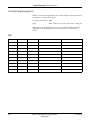
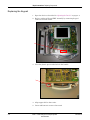
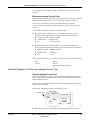
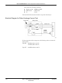
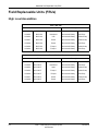
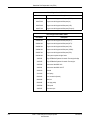
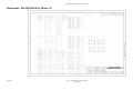
1
GE Healthcare MAC™ 1200/MAC™ 1200 ST Resting ECG Analysis System (2018357-003 & 2013503-003 PWAs) Service Manual 2012250-095 g Revision A NOTE: The information in this manual only applies to MAC™ 1200 resting ECG analysis system with the 2018357-003 or 2013503-003 board and software v6.2. It does not apply to earlier software versions. Due to continuing product innovation, specifications in this manual are subject to change without notice. CAUTION Software compatibility issue. Attempting to download: v6.2 software or later into -002 boards (PN 2018357-001, 2018357-002, 2013503-001 or 38803267) or v6.11 software or earlier into -003 boards (PN 2018357-003 or 2013503-003) will render the MAC 1200 unit inoperable. MAC® and MUSE® owned by GE Medical Systems Information Technologies, a General Electric company, going to market as GE Healthcare. All other marks are owned by their respective owners. © 2007 General Electric Company. All rights reserved. T-2 MAC™ 1200 resting ECG analysis system 2012250-095 Revision A 22 May 2007 CE Marking Information CE Marking Information Compliance The MAC™ 1200 resting ECG analysis system bears CE mark CE-0459 indicating its conformity with the provisions of the Council Directive 93/ 42/EEC concerning medical devices and fulfills the essential requirements of Annex I of this directive. The product is in radiointerference protection class A in accordance with EN 55011. The country of manufacture can be found on the equipment labeling. The product complies with the requirements of standard EN 60601-1-2 “Electromagnetic Compatibility - Medical Electrical Equipment”. The safety and effectiveness of this device has been verified against previously distributed devices. Although all standards applicable to presently marketed devices may not be appropriate for prior devices (i.e. electromagnetic compatibility standards), this device will not impair the safe and effective use of those previously distributed devices. See user’s information. Exceptions The MAC™ 1200 resting ECG analysis system EMC: Immunity Performance Users should be aware of known RF sources, such as radio or TV stations and hand-held or mobile two-way radios, and consider them when installing a medical device or system. Be aware that adding accessories or components, or modifying the medical device or system may degrade the EMI performance. Consult with qualified personnel regarding changes to the system configuration. Revision A MAC™ 1200 resting ECG analysis system 2012250-095 CE-1 CE Marking Information For your notes CE-2 MAC™ 1200 resting ECG analysis system 2012250-095 Revision A Contents 1 The Basics . . . . . . . . . . . . . . . . . . . . . . . . . . . . . . . . . . . . . 1-1 About This Manual . . . . . . . . . . . . . . . . . . . . . . . . . . . . . . . . . . . . . . . . . . . . . . . . . . . 1-3 Manual Purpose . . . . . . . . . . . . . . . . . . . . . . . . . . . . . . . . . . . . . . . . . . . . . . . . . . . 1-3 Intended Audience . . . . . . . . . . . . . . . . . . . . . . . . . . . . . . . . . . . . . . . . . . . . . . . . . 1-3 Definitions . . . . . . . . . . . . . . . . . . . . . . . . . . . . . . . . . . . . . . . . . . . . . . . . . . . . . . . 1-3 Illustrations and Names . . . . . . . . . . . . . . . . . . . . . . . . . . . . . . . . . . . . . . . . . . . . . 1-4 Revision History . . . . . . . . . . . . . . . . . . . . . . . . . . . . . . . . . . . . . . . . . . . . . . . . . . . 1-4 Basic Information . . . . . . . . . . . . . . . . . . . . . . . . . . . . . . . . . . . . . . . . . . . . . . . . . . . 1-5 Variants of the MAC™ 1200 resting ECG analysis system . . . . . . . . . . . . . . . . . . 1-6 Hardware Functional Blocks . . . . . . . . . . . . . . . . . . . . . . . . . . . . . . . . . . . . . . . . . 1-6 Block Circuit Diagram of Entire Instrument . . . . . . . . . . . . . . . . . . . . . . . . . . . . . . 1-7 Mechanical Components . . . . . . . . . . . . . . . . . . . . . . . . . . . . . . . . . . . . . . . . . . . . . 1-8 2 Functional Description . . . . . . . . . . . . . . . . . . . . . . . . . . . 2-1 Basic Information . . . . . . . . . . . . . . . . . . . . . . . . . . . . . . . . . . . . . . . . . . . . . . . . . . . 2-3 Switching Power Supply . . . . . . . . . . . . . . . . . . . . . . . . . . . . . . . . . . . . . . . . . . . . . . 2-4 PCB NC Battery Charge . . . . . . . . . . . . . . . . . . . . . . . . . . . . . . . . . . . . . . . . . . . . . . 2-5 Charging Circuit for the NC Battery . . . . . . . . . . . . . . . . . . . . . . . . . . . . . . . . . . . . 2-5 Battery-Dependent Device Behavior . . . . . . . . . . . . . . . . . . . . . . . . . . . . . . . . . . . 2-6 PCB Control CS_CI . . . . . . . . . . . . . . . . . . . . . . . . . . . . . . . . . . . . . . . . . . . . . . . . . . 2-7 Generation of Internal Power Supplies . . . . . . . . . . . . . . . . . . . . . . . . . . . . . . . . . 2-7 Switch On/Off Circuit . . . . . . . . . . . . . . . . . . . . . . . . . . . . . . . . . . . . . . . . . . . . . . . 2-8 ECG Recording and Front-End Processing . . . . . . . . . . . . . . . . . . . . . . . . . . . . . . 2-9 Controller Core . . . . . . . . . . . . . . . . . . . . . . . . . . . . . . . . . . . . . . . . . . . . . . . . . . . 2-10 Real Time Clock . . . . . . . . . . . . . . . . . . . . . . . . . . . . . . . . . . . . . . . . . . . . . . . . . . 2-11 Memory . . . . . . . . . . . . . . . . . . . . . . . . . . . . . . . . . . . . . . . . . . . . . . . . . . . . . . . . 2-12 LCD Graphics Display Interface . . . . . . . . . . . . . . . . . . . . . . . . . . . . . . . . . . . . . . 2-12 Revision A MAC™ 1200 resting ECG analysis system 2012250-095 i Modem Supply . . . . . . . . . . . . . . . . . . . . . . . . . . . . . . . . . . . . . . . . . . . . . . . . . . . . . 2-17 Internal Interfaces . . . . . . . . . . . . . . . . . . . . . . . . . . . . . . . . . . . . . . . . . . . . . . . . . . 2-18 Mechanical Interfaces . . . . . . . . . . . . . . . . . . . . . . . . . . . . . . . . . . . . . . . . . . . . . 2-18 Electronic Interfaces . . . . . . . . . . . . . . . . . . . . . . . . . . . . . . . . . . . . . . . . . . . . . . 2-18 Interfaces to Peripherals . . . . . . . . . . . . . . . . . . . . . . . . . . . . . . . . . . . . . . . . . . . . . 2-23 Electronic Interfaces . . . . . . . . . . . . . . . . . . . . . . . . . . . . . . . . . . . . . . . . . . . . . . 2-24 Limitations . . . . . . . . . . . . . . . . . . . . . . . . . . . . . . . . . . . . . . . . . . . . . . . . . . . . . . . . 2-26 3 System Test Function . . . . . . . . . . . . . . . . . . . . . . . . . . . . 3-1 General Information . . . . . . . . . . . . . . . . . . . . . . . . . . . . . . . . . . . . . . . . . . . . . . . . . . 3-3 Test Start . . . . . . . . . . . . . . . . . . . . . . . . . . . . . . . . . . . . . . . . . . . . . . . . . . . . . . . . . . 3-4 Display Test . . . . . . . . . . . . . . . . . . . . . . . . . . . . . . . . . . . . . . . . . . . . . . . . . . . . . . . . 3-5 Contrast Control . . . . . . . . . . . . . . . . . . . . . . . . . . . . . . . . . . . . . . . . . . . . . . . . . . . 3-5 Keyboard Test . . . . . . . . . . . . . . . . . . . . . . . . . . . . . . . . . . . . . . . . . . . . . . . . . . . . . . 3-6 Motor Test . . . . . . . . . . . . . . . . . . . . . . . . . . . . . . . . . . . . . . . . . . . . . . . . . . . . . . . . . 3-7 Test Results . . . . . . . . . . . . . . . . . . . . . . . . . . . . . . . . . . . . . . . . . . . . . . . . . . . . . . . . 3-8 Self-Test . . . . . . . . . . . . . . . . . . . . . . . . . . . . . . . . . . . . . . . . . . . . . . . . . . . . . . . . . . . 3-9 Error Codes . . . . . . . . . . . . . . . . . . . . . . . . . . . . . . . . . . . . . . . . . . . . . . . . . . . . . . 3-9 Recording Test . . . . . . . . . . . . . . . . . . . . . . . . . . . . . . . . . . . . . . . . . . . . . . . . . . . . . 3-10 V24 Tests . . . . . . . . . . . . . . . . . . . . . . . . . . . . . . . . . . . . . . . . . . . . . . . . . . . . . . . . . 3-11 Sending and Receiving (1) . . . . . . . . . . . . . . . . . . . . . . . . . . . . . . . . . . . . . . . . . . 3-11 Send Test String to Device (2) . . . . . . . . . . . . . . . . . . . . . . . . . . . . . . . . . . . . . . . 3-11 Send and Receive with Device (3) . . . . . . . . . . . . . . . . . . . . . . . . . . . . . . . . . . . . 3-12 Time and Date . . . . . . . . . . . . . . . . . . . . . . . . . . . . . . . . . . . . . . . . . . . . . . . . . . . . . 3-13 Electrode Test . . . . . . . . . . . . . . . . . . . . . . . . . . . . . . . . . . . . . . . . . . . . . . . . . . . . . 3-14 Time Constant/Baseline Roll Filter . . . . . . . . . . . . . . . . . . . . . . . . . . . . . . . . . . . . 3-15 Setting the Device Model . . . . . . . . . . . . . . . . . . . . . . . . . . . . . . . . . . . . . . . . . . . . 3-16 Interpretation (International Device Models Only) . . . . . . . . . . . . . . . . . . . . . . . . 3-18 Pace Enhance . . . . . . . . . . . . . . . . . . . . . . . . . . . . . . . . . . . . . . . . . . . . . . . . . . . . . 3-19 Serial Number . . . . . . . . . . . . . . . . . . . . . . . . . . . . . . . . . . . . . . . . . . . . . . . . . . . . . 3-20 ii MAC™ 1200 resting ECG analysis system 2012250-095 Revision A Ergometer / Treadmills (JAPAN Device Model Only) . . . . . . . . . . . . . . . . . . . . . . 3-21 ACI-TIPI (US Device Models Only) . . . . . . . . . . . . . . . . . . . . . . . . . . . . . . . . . . . . . 3-22 Pharma . . . . . . . . . . . . . . . . . . . . . . . . . . . . . . . . . . . . . . . . . . . . . . . . . . . . . . . . . . . 3-23 High Security . . . . . . . . . . . . . . . . . . . . . . . . . . . . . . . . . . . . . . . . . . . . . . . . . . . . 3-23 4 Repair Instructions . . . . . . . . . . . . . . . . . . . . . . . . . . . . . . . . 1 Safety Instructions . . . . . . . . . . . . . . . . . . . . . . . . . . . . . . . . . . . . . . . . . . . . . . . . . . . . . 3 Replacing Components . . . . . . . . . . . . . . . . . . . . . . . . . . . . . . . . . . . . . . . . . . . . . . . . . 4 Opening the Device . . . . . . . . . . . . . . . . . . . . . . . . . . . . . . . . . . . . . . . . . . . . . . . . . 4 5 Troubleshooting . . . . . . . . . . . . . . . . . . . . . . . . . . . . . . . . 5-1 Basic Information . . . . . . . . . . . . . . . . . . . . . . . . . . . . . . . . . . . . . . . . . . . . . . . . . . . . 5-3 6 Adjustment Instructions . . . . . . . . . . . . . . . . . . . . . . . . . . 6-1 Basic Information . . . . . . . . . . . . . . . . . . . . . . . . . . . . . . . . . . . . . . . . . . . . . . . . . . . . 6-3 7 Service and Maintenance . . . . . . . . . . . . . . . . . . . . . . . . . 7-1 Technical Inspections/Preventative Maintenance . . . . . . . . . . . . . . . . . . . . . . . . . 7-3 Visual Check . . . . . . . . . . . . . . . . . . . . . . . . . . . . . . . . . . . . . . . . . . . . . . . . . . . . . 7-4 Test Functions . . . . . . . . . . . . . . . . . . . . . . . . . . . . . . . . . . . . . . . . . . . . . . . . . . . . 7-4 Safety Analysis Tests . . . . . . . . . . . . . . . . . . . . . . . . . . . . . . . . . . . . . . . . . . . . . . . 7-8 Maintenance, Cleaning, and Disinfection . . . . . . . . . . . . . . . . . . . . . . . . . . . . . . . 7-11 8 Parts List . . . . . . . . . . . . . . . . . . . . . . . . . . . . . . . . . . . . . . 8-1 Introduction . . . . . . . . . . . . . . . . . . . . . . . . . . . . . . . . . . . . . . . . . . . . . . . . . . . . . . . . 8-3 Field Replaceable Units (FRUs) . . . . . . . . . . . . . . . . . . . . . . . . . . . . . . . . . . . . . . . . 8-4 High Level Assemblies . . . . . . . . . . . . . . . . . . . . . . . . . . . . . . . . . . . . . . . . . . . . . . 8-4 Revision A MAC™ 1200 resting ECG analysis system 2012250-095 iii 9 Specifications . . . . . . . . . . . . . . . . . . . . . . . . . . . . . . . . . . 9-1 Basic Information . . . . . . . . . . . . . . . . . . . . . . . . . . . . . . . . . . . . . . . . . . . . . . . . . . . 9-3 Recording . . . . . . . . . . . . . . . . . . . . . . . . . . . . . . . . . . . . . . . . . . . . . . . . . . . . . . . . 9-3 Printer Paper . . . . . . . . . . . . . . . . . . . . . . . . . . . . . . . . . . . . . . . . . . . . . . . . . . . . . 9-3 Paper Transport . . . . . . . . . . . . . . . . . . . . . . . . . . . . . . . . . . . . . . . . . . . . . . . . . . . 9-4 Membrane Keypad . . . . . . . . . . . . . . . . . . . . . . . . . . . . . . . . . . . . . . . . . . . . . . . . . 9-4 Display . . . . . . . . . . . . . . . . . . . . . . . . . . . . . . . . . . . . . . . . . . . . . . . . . . . . . . . . . . 9-4 Indicators (LEDs) . . . . . . . . . . . . . . . . . . . . . . . . . . . . . . . . . . . . . . . . . . . . . . . . . . 9-4 Automatic Functions . . . . . . . . . . . . . . . . . . . . . . . . . . . . . . . . . . . . . . . . . . . . . . . 9-4 Detection of Pacer Pulses . . . . . . . . . . . . . . . . . . . . . . . . . . . . . . . . . . . . . . . . . . . 9-5 Heart Rate Indication . . . . . . . . . . . . . . . . . . . . . . . . . . . . . . . . . . . . . . . . . . . . . . . 9-5 Signal Inputs . . . . . . . . . . . . . . . . . . . . . . . . . . . . . . . . . . . . . . . . . . . . . . . . . . . . . 9-5 Data Interface . . . . . . . . . . . . . . . . . . . . . . . . . . . . . . . . . . . . . . . . . . . . . . . . . . . . 9-6 Pin Assignment of Data Port . . . . . . . . . . . . . . . . . . . . . . . . . . . . . . . . . . . . . . . . . 9-6 Remote Start (Hardware) . . . . . . . . . . . . . . . . . . . . . . . . . . . . . . . . . . . . . . . . . . . . 9-6 Signal Transmission . . . . . . . . . . . . . . . . . . . . . . . . . . . . . . . . . . . . . . . . . . . . . . . . 9-7 ECG Calibration . . . . . . . . . . . . . . . . . . . . . . . . . . . . . . . . . . . . . . . . . . . . . . . . . . . 9-8 Automatic ECG Gain Adjustment . . . . . . . . . . . . . . . . . . . . . . . . . . . . . . . . . . . . . . 9-8 Baseline . . . . . . . . . . . . . . . . . . . . . . . . . . . . . . . . . . . . . . . . . . . . . . . . . . . . . . . . . 9-8 Anti-Drift System (ADS) (Cubic Spline) . . . . . . . . . . . . . . . . . . . . . . . . . . . . . . . . . 9-8 ECG Storage . . . . . . . . . . . . . . . . . . . . . . . . . . . . . . . . . . . . . . . . . . . . . . . . . . . . . 9-8 Blocking . . . . . . . . . . . . . . . . . . . . . . . . . . . . . . . . . . . . . . . . . . . . . . . . . . . . . . . . . 9-9 Electrode Monitoring . . . . . . . . . . . . . . . . . . . . . . . . . . . . . . . . . . . . . . . . . . . . . . . 9-9 Text Input . . . . . . . . . . . . . . . . . . . . . . . . . . . . . . . . . . . . . . . . . . . . . . . . . . . . . . . . 9-9 Copy Function . . . . . . . . . . . . . . . . . . . . . . . . . . . . . . . . . . . . . . . . . . . . . . . . . . . . 9-9 Test . . . . . . . . . . . . . . . . . . . . . . . . . . . . . . . . . . . . . . . . . . . . . . . . . . . . . . . . . . . . 9-9 Power Supply . . . . . . . . . . . . . . . . . . . . . . . . . . . . . . . . . . . . . . . . . . . . . . . . . . . . . 9-9 Mains Operation . . . . . . . . . . . . . . . . . . . . . . . . . . . . . . . . . . . . . . . . . . . . . . . . . . 9-10 Battery Operation . . . . . . . . . . . . . . . . . . . . . . . . . . . . . . . . . . . . . . . . . . . . . . . . . 9-10 Operational Readiness . . . . . . . . . . . . . . . . . . . . . . . . . . . . . . . . . . . . . . . . . . . . 9-10 Operating Position . . . . . . . . . . . . . . . . . . . . . . . . . . . . . . . . . . . . . . . . . . . . . . . . 9-10 Environment . . . . . . . . . . . . . . . . . . . . . . . . . . . . . . . . . . . . . . . . . . . . . . . . . . . . . 9-11 Recorder Dimensions . . . . . . . . . . . . . . . . . . . . . . . . . . . . . . . . . . . . . . . . . . . . . 9-11 Weight . . . . . . . . . . . . . . . . . . . . . . . . . . . . . . . . . . . . . . . . . . . . . . . . . . . . . . . . . 9-11 10 Drawings . . . . . . . . . . . . . . . . . . . . . . . . . . . . . . . . . . . . . 10-1 Basic Information . . . . . . . . . . . . . . . . . . . . . . . . . . . . . . . . . . . . . . . . . . . . . . . . . . 10-2 High Level Assembly, PN 101 168 01...38, Sheet 1 . . . . . . . . . . . . . . . . . . . . . . . 10-3 High Level Assembly, PN 101 168 01...38, Sheet 2 . . . . . . . . . . . . . . . . . . . . . . . 10-4 PCB Assembly Drawing, PN 2033914-027 . . . . . . . . . . . . . . . . . . . . . . . . . . . . . . . 10-5 Schematic, PN 2033914-033, Sheet 1 . . . . . . . . . . . . . . . . . . . . . . . . . . . . . . . . . . . 10-6 iv MAC™ 1200 resting ECG analysis system 2012250-095 Revision A Schematic, PN 2033914-033, Sheet 2 . . . . . . . . . . . . . . . . . . . . . . . . . . . . . . . . . . . 10-7 Schematic, PN 2033914-033, Sheet 3 . . . . . . . . . . . . . . . . . . . . . . . . . . . . . . . . . . . 10-8 Schematic, PN 2033914-033, Sheet 4 . . . . . . . . . . . . . . . . . . . . . . . . . . . . . . . . . . . 10-9 Schematic, PN 2033914-033, Sheet 5 . . . . . . . . . . . . . . . . . . . . . . . . . . . . . . . . . . 10-10 Schematic, PN 2033914-033, Sheet 6 . . . . . . . . . . . . . . . . . . . . . . . . . . . . . . . . . . 10-11 Schematic, PN 2033914-033, Sheet 7 . . . . . . . . . . . . . . . . . . . . . . . . . . . . . . . . . . 10-12 Schematic, PN 2033914-033, Sheet 8 . . . . . . . . . . . . . . . . . . . . . . . . . . . . . . . . . . 10-13 Schematic, PN 2033914-033, Sheet 9 . . . . . . . . . . . . . . . . . . . . . . . . . . . . . . . . . . 10-14 Schematic, PN 2033914-033, Sheet 10 . . . . . . . . . . . . . . . . . . . . . . . . . . . . . . . . . 10-15 Schematic, PN 2033914-033, Sheet 11 . . . . . . . . . . . . . . . . . . . . . . . . . . . . . . . . . 10-16 Schematic, PN 2033914-033, Sheet 12 . . . . . . . . . . . . . . . . . . . . . . . . . . . . . . . . . 10-17 Schematic, PN 2033914-033, Sheet 13 . . . . . . . . . . . . . . . . . . . . . . . . . . . . . . . . . 10-18 Schematic, PN 2033914-033, Sheet 14 . . . . . . . . . . . . . . . . . . . . . . . . . . . . . . . . . 10-19 Schematic, PN 2033914-033, Sheet 15 . . . . . . . . . . . . . . . . . . . . . . . . . . . . . . . . . 10-20 Schematic, PN 2033914-033, Sheet 16 . . . . . . . . . . . . . . . . . . . . . . . . . . . . . . . . . 10-21 Schematic, PN 2033914-033, Sheet 17 . . . . . . . . . . . . . . . . . . . . . . . . . . . . . . . . . 10-22 Schematic, PN 2033914-033, Sheet 18 . . . . . . . . . . . . . . . . . . . . . . . . . . . . . . . . . 10-23 Schematic, PN 2033914-033, Sheet 19 . . . . . . . . . . . . . . . . . . . . . . . . . . . . . . . . . 10-24 Schematic, PN 2033914-033, Sheet 20 . . . . . . . . . . . . . . . . . . . . . . . . . . . . . . . . . 10-25 PCB Battery Charge CS_CSI, PN 388 032 90, Sheet 1 . . . . . . . . . . . . . . . . . . . . 10-26 PCB Battery Charge CS_CSI, PN 388 032 90, Sheet 2 . . . . . . . . . . . . . . . . . . . . 10-27 Revision A MAC™ 1200 resting ECG analysis system 2012250-095 v For your notes vi MAC™ 1200 resting ECG analysis system 2012250-095 Revision A 1 Revision A The Basics MAC™ 1200 resting ECG analysis system 2012250-095 1-1 For your notes 1-2 MAC™ 1200 resting ECG analysis system 2012250-095 Revision A The Basics: About This Manual About This Manual Manual Purpose This manual supplies technical information for service representative and technical personnel so they can maintain the equipment to the assembly level. Use it as a guide for maintenance and electrical repairs that are considered field repairable. Where necessary the manual identifies additional sources of relevant information and or technical assistance. See the operator manual for the instructions necessary to operate the equipment safely in accordance with its function and intended use. This manual addresses both MAC 1200/1200ST units (international units) and MAC 1200 units (USA units). Information that is specific to either unit is identified. Intended Audience This manual is intended for the person who uses, maintains, or troubleshoots this equipment. Definitions The following formats are used in this manual to highlight various web viewer features and functions. Revision A Black text Indicates keys on the keyboard, text to be entered, or hardware items such as buttons or switches on the equipment. Italicized text Indicates software terms that identify menu items, buttons, or options in various windows. Ctrl+Esc Indicates a keyboard operation. A (+) sign between the names of two keys indicates that you must press and hold the first key while pressing the second key once. For example, “Press Ctrl+Esc” means to press and hold down the Ctrl key while pressing the Esc key. <Space> Indicates you must press the spacebar. When instructions are given for typing a precise text string with one or more spaces, the point where the spacebar must be pressed is indicated as: <Space>. The purpose of the < > brackets is to ensure you press the spacebar when required. Enter Indicates you must press the “Enter” or “Return” key on the keyboard. Do not type “enter”. MAC™ 1200 resting ECG analysis system 2012250-095 1-3 The Basics: About This Manual Illustrations and Names All illustrations in this manual are provided as examples only. They may not necessarily reflect your monitoring setup or data displayed on your monitor. In this manual, all names appearing in examples and illustrations are fictitious. The use of any real person’s name is purely coincidental. Revision History This manual has a revision letter, located at the bottom of each page. This revision letter changes whenever the manual is updated. Revision A is the initial release of the document. Table 1. Revision History, PN 2012250-095 1-4 Revision Date A 22 May 2007 Comments Initial release of this manual. MAC™ 1200 resting ECG analysis system 2012250-095 Revision A The Basics: Basic Information Basic Information This service manual describes software version 6 of MAC™ 1200 resting ECG analysis system. The MAC™ 1200 resting ECG analysis system is a portable electrocardiograph with an integrated printing unit. It is used to acquire, record and process ECG signals. The integrated LCD graphics display shows three ECG channels. It also displays status information, filter settings, speed/format, gain and the status of the electrodes. With the setup feature, users can set up the device and the modes for his own needs. The MAC™ 1200 resting ECG analysis system offers three modes of operation: International USA Automatic 12-lead Manual 6-lead Arrhythmia Arrhythmia ECGs acquired in automatic (12-lead) mode can be transmitted to the MUSE or CardioSys system directly or via modem. A NC-battery with a charging circuit is integrated into the unit. In addition, a pump for the KISS system can be integrated into the instrument as a separate option. NC battery with charging circuit is integrated in general Automatic mode with CSI protocol for transmission Automatic mode with interpretation (Option Code) Automatic mode with storage for up to 40 ECGs (Option Code) The acquired ECGs can be transmitted to MUSE or CardioSys directly or via a Modem. Additionally the MAC 1200 ST can run stress test operating mode (Option Code). To control stress test devices the MAC 1200 ST has a modified keyboard with additional keys for stress test. Revision A MAC™ 1200 resting ECG analysis system 2012250-095 1-5 The Basics: Basic Information Variants of the MAC™ 1200 resting ECG analysis system The complete list of the variants is included in Chapter 8, “Parts List”. The following table gives an overview of the different device models of the MAC™ 1200 resting ECG analysis system. Device Device Model Manufacturer ID Keypad Labeling Mains Voltage MAC1200 MAC1200 ST INT GE Medical Systems Icons International 230V MAC1200 MAC1200 ST Europe 2 GE Medical Systems Text International 230V MAC1200 MAC1200 ST USA GE Medical Systems Text USA 115V MAC1200 RUSS GE Medical Systems Kyrillian International 230V MAC1200 ST Japan GE Medical Systems Japanese International 230V Pharma GE Medical Systems Text USA 115V MAC1200 Hardware Functional Blocks The main functional blocks for the MAC™ 1200 resting ECG analysis system are listed below. 1-6 Switching power supply PCB Control CS_CI Printing unit Keypad 1/4 VGA graphics display, monochrome MAC™ 1200 resting ECG analysis system 2012250-095 Revision A The Basics: Block Circuit Diagram of Entire Instrument Block Circuit Diagram of Entire Instrument MAC 1200 (US), Version 6.2 Program Memory Boot Loader Modem Supply ECG RAM Buffered Internal RAM Configuration Memory ECG Input ECG Acquisition and Conditioning Controller Core Real Time Clock Buffered RS232 Driver Keypad Interface Keypad Display Interface LCD Graphics Display Display Supply Line Power Input Device On/Off Control 1/4 VGA Monochrome Motor Control Motor Thermal Pinhead Control Thermal Printhead Pump Interface (not in US Device) Option Pump (Not in US Device) Logic Supply +5 V +3.3 V Analog Supply Printhead Supply RS232 Interface Printing Unit PCB Control SC_CI Line Power Input with Fuse NC Battery Switching Power Supply +26.5 V PCB NC Battery Charge Line Power, NC Battery Revision A MAC™ 1200 resting ECG analysis system 2012250-095 1-7 The Basics: Mechanical Components Mechanical Components The main mechanical components comprise the upper and lower shell of the MAC™ 1200 resting ECG analysis system. The lower shell serves as a basic unit to receive the following assemblies. Line power input module with fuse Switching power supply NC Battery PCB NC Battery Charge PCB Control CS_CI Graphics display Thermal printing unit Paper container The upper shell accommodates the keypad, which is connected to the PCB Control CS_CI via a 26-pin connector. The MAC™ 1200 resting ECG analysis system can be opened by releasing 5 screws at the bottom of the lower shell, opening the paper flap and lifting up the upper shell a little bit to remove the keypad cable from the PCB Control CS_CI. The upper shell then can be removed completely. To replace the NC Battery, the battery flap at the bottom of the lower shell must first be unlocked with a screw-driver before it can be removed. The 15-pin input connector to connect the patient cable and the 9-pin connector for the RS-232 interface are located directly on the PCB Control CS_CI. 1-8 MAC™ 1200 resting ECG analysis system 2012250-095 Revision A 2 Revision A Functional Description MAC™ 1200 resting ECG analysis system 2012250-095 2-1 For your notes 2-2 MAC™ 1200 resting ECG analysis system 2012250-095 Revision A Functional Description: Basic Information Basic Information The block circuit diagram of the entire instrument in Chapter 1, “Block Circuit Diagram of Entire Instrument” and the functional blocks of circuit diagram sheets (P-plans) describe the individual functional blocks. Revision A MAC™ 1200 resting ECG analysis system 2012250-095 2-3 Functional Description: Switching Power Supply Switching Power Supply The switching power supply generates the fundamental device voltage for the PCB Control CS_CI and for the PCB NC Battery Charge. It has the following input specifications. Input voltage range: 85 ... 264 Vac Line frequency range: 47 ... 65 Hz The output voltage is +26.5 Vdc, the maximum load is 1.5 A. 2-4 MAC™ 1200 resting ECG analysis system 2012250-095 Revision A Functional Description: PCB NC Battery Charge PCB NC Battery Charge The MAC™ 1200 resting ECG analysis system can operate on battery power. With a new, fully charged NC battery, up to 50 ECGs can be recorded in Automatic (12-lead) mode. The PCB NC battery charge controls and monitors the charging process, depending on the status of the battery and the status of the device. Charging Circuit for the NC Battery An integrated charging device is used to charge the battery. During charging, it monitors the battery voltage function and switches over from rapid charging to trickle charging. Applying the line power to the MAC™ 1200 resting ECG analysis system, or insertion of the battery activates the charging circuit. During a recording, the charging current is reduced. In standby mode, a depleted battery is fully charged within 4 hours. Revision A MAC™ 1200 resting ECG analysis system 2012250-095 2-5 Functional Description: PCB NC Battery Charge Battery-Dependent Device Behavior Depending on the status of the battery and the status of the device, the following behavior occurs. Table 1. Battery State 2-6 State 1 Battery depleted, line power supply is connected up Battery charged in rapid mode; when fully charged, switchover to trickle charging. State 2 Battery full, line power supply is connected up Battery charged in rapid mode for some minutes till the charging circuit recognizes battery full, then switchover to trickle charging. State 3 Battery depleted, no line power supply, device is switched on Device inoperative. State 4 Battery full, no line power supply, device is switched on Device fully operative. When battery is almost depleted, the LEDBAT signal is activated to indicate that the device should be charged by connecting to the line power supply. If the operation is continued without line power, MAC 1200/ 1200 ST will shut down itself when a minimum level is reached to prevent the battery from a excessive discharge. State 5 Battery depleted, line power supply is connected up, device is switched on Battery is charged in rapid mode, device is fully operative, including recording. During recording, the charging current is reduced. If a lot of recordings take place in this phase, the battery is not fully charged within 4 hours. MAC™ 1200 resting ECG analysis system 2012250-095 Revision A Functional Description: PCB Control CS_CI PCB Control CS_CI The PCB Control CS_CI is the main board of the MAC™ 1200 resting ECG analysis system. The main board accommodates the control functions of the device, except the line power supply and the NC batterycharging controller. Generation of Internal Power Supplies Logic Power Supply +5 V and +3.3 V The processor core and the memory is a fully +3.3 V design. The interface functions to display, to RS-232, to the printing unit and to the ECG acquisition unit are supplied with +5 V. Both the +3.3 V and the +5 V are generated separately by a clock-rated voltage controller. By using the “adjustable version” of the voltage controller, both supplies are based on the same voltage controller. The output voltage is determined by appropriate dimensioning of the voltage divider at the feedback input of the voltage controller. Standby Supply +5 VSTB and +3.3 VSTB The standby supply + 5VSTB supplies the ON/OFF Control, the + 3.3 VSTB buffers the patient ECG memory when the device is turned off. Both supplies are generated together from one low-power linear regulator with low quiescent supply current. Analog Supply +12 V +12 V is used for the heating control and temperature monitoring of the printing unit, which requires only a current of a few milliamperes. This supply is generated by a linear regulator with feedback input. FPGA Power Supply +2.5V +1.25V +2.5 V is the auxilliary source of power and +1.25 V is the main power supply for the FPGA internal logic. These voltages are generated by Dual Output Low Dropout Regulator. Revision A MAC™ 1200 resting ECG analysis system 2012250-095 2-7 Functional Description: PCB Control CS_CI Switch On/Off Circuit The Switch On/Off circuit consists of the On/Off control and the Voltage control. The On/Off control switches the device on or off by switching the device supplies +UVERS and +USUPPSW. The On/Off control is supplied from the +5 VSTB. Device On Sequence The transition from device Off state, or Standby state when line power is connected, to device On state can only be activated by pressing the On/ Off button. Device Off Sequence The transition from device On state to device Off state or Standby state when line power is connected can be achieved as follows. Pressing the On/Off button. When the control core activates the signal DEV_OFF. When the voltage control applies the signal REG_OFF_, because the battery voltage gets too low during battery operation. The Voltage Control controls the battery voltage during battery operation. The signal BATT_LEV2 indicates that the battery charge has gone down, and the device should be connected to the line power soon. The signal BAT_LEV1 indicates that the battery has been discharged almost completely, the device should be connected to the line power immediately, otherwise the device will shut down within few minutes. If battery discharge is continued without connecting to the line power, the signal REG_OFF_ is activated and the device is switched off. 2-8 MAC™ 1200 resting ECG analysis system 2012250-095 Revision A Functional Description: PCB Control CS_CI ECG Recording and Front-End Processing The patient input is classified as being cardiac floating and is defibrillation-proof. The patient leads are connected with a 15-pin connector with a special form for the specified and released patient cables for the MAC™ 1200 resting ECG analysis system. The main element of the ECG recording and front-end processing is a set of chips comprising 3 ASICs. Pace detection is realized by a separate circuit. Every disconnected electrode is detected by a special AC measurement, which allows higher impedance between electrode and patient. N common-mode compensation ensures suppression of interference, at the same time serving to improve the in-phase suppression of the input electrodes. To protect patients, the ECG recording and front-end processing are assembled as floating components. Digital signals from and to the controller core are transmitted via opto-electronic couplers. The floating supply ±5 V is generated by an isolated flyback converter from the +5 V logic power supply. Revision A MAC™ 1200 resting ECG analysis system 2012250-095 2-9 Functional Description: PCB Control CS_CI Controller Core The actual core comprises the Motorola Power PC MPC855T, which contains the following integrated components. Chipselect logic DRAM controller SCC and SMC for RS-232 SPI interface I/O ports Real-time clock counter register In addition, the MPC855T contains a JTAG port with test and programming capabilities. The MPC855T has the following additional power supplies. VDDSYN, filtered from the +3.3 V logic supply, for the clock generation. KAPWR, generated from the +3.3 V logic supply or from a battery when device is off, used for buffering the RTC Counter Register. The clock generation for the MPC855T is realized by a quartz oscillator with 32.768 KHz. The system clock CLOCKOUT is adjusted with the internal PLL register. The system frequency is 25 MHz. The watchdog/reset generation is implemented separately in an integrated system monitoring chip. It has the following functions. 2-10 Power-up reset for the MPC855T when the device is switched on. Voltage monitoring of the +3.3 V and +5 V with reset generation. Watchdog Switchover to battery supply for patient ECG memory when device is switched off. Signal for access protection for patient ECG memory when device is switched off. MAC™ 1200 resting ECG analysis system 2012250-095 Revision A Functional Description: PCB Control CS_CI The Reset Configuration defines startup conditions like boot port size and clock generation source. Four LEDs indicate the device status in addition to the following. LED1: Active when a HRESET_ occurs. LED2: Indicator for the logic supply. LED3, LED4: Indicate internal software states. The control register comprises device control signals to switch off the device, control battery charging and display control signals. The status register contains information on the device hardware configuration and the state of the battery charge. Real Time Clock With software version 6, two options for the real time clock are supported. The software checks for an external real time clock chip (X13 on PWA control). This chip is available with Index G of PWA Control CS_CI and Index F of PWA Control CS_C. If the external RTC is found, it will be used for the clock function. If not, the internal clock of the MPC855T will be used. The external RTC is more accurate than the internal one. Both clocks are buffered by the voltage KAPWR. Revision A MAC™ 1200 resting ECG analysis system 2012250-095 2-11 Functional Description: PCB Control CS_CI Memory The complete memory of the MAC™ 1200 resting ECG analysis system is located on the PCB Control CS_C(I). The software of the device can be loaded through the JTAG port during the production process, or for service purposes with the appropriate programming software through the RS-232 interface. Program Memory Type: Flash, +3.3 V supply Organization: 2Mbit X 16, 4Mbyte Wait states: 1 wait state Type: SDRAM, +3.3 V supply Organization: 4Mbit X 16, 8Mbyte Wait States: 0 wait state Type: Buffered SRAM, +3.3 V supply Organization: 512Kwords X 16 bits Wait States: 1 wait state DRAM Patient ECG Memory Configuration Memory The configuration memory is part of the program memory Flash. With special hardware and software protection facilities, write access to the Flash is only possible in the defined configuration memory of the Flash. Thus an external configuration memory like an EEPROM is not required. LCD Graphics Display Interface The LCD controller is now implemented in FPGA. Controller Interface For the digital control signals, delivered from the MPC855T, only an output driver is required. 2-12 MAC™ 1200 resting ECG analysis system 2012250-095 Revision A Functional Description: PCB Control CS_CI LCD Power Supply The LCD power supply VEE of –23 V is generated from the +5 V logic supply. The generation starts after HRESET_ becomes inactive to ensure that the logic supply of +5 V first is applied to the display. Adjusting Contrast Contrast adjustment of the display is accomplished with the contrast voltage V0. The level of V0 is controlled with the PWM signal BLCD_CONTR from the timer module of the MPC855T. In addition, the contrast voltage is temperature compensated. Backlight The LCD backlight converter for the CCFL tube is located on the PCB Control CS_CI too. The backlight converter is generated from the +5 V logic power supply. The signal BLCD_ENBA switches the backlight on or off. The user can define the backlight active time in the configuration menu. Revision A MAC™ 1200 resting ECG analysis system 2012250-095 2-13 Functional Description: PCB Control CS_CI Keypad Interface The keypad interface contains the control register for 8 keypad columns and the receiving register for 7 keypad rows, and the control signals for the status LEDs: LED_LIN, LED_BATT_, LED_START, and LED_STOP. Using the matrix of 8 x 7, up to 56 keypads can be detected. Identification of the key pressed is as follows. The controller activates a column, activation is via low-level, then the row-register is read to identify the pressed key by a low-level. This procedure is repeated with the next column, till all columns have been activated. Printhead Control The printhead controller takes on the complete control of the 216-mm thermal printhead with a line width of 200 mm. The output rate to the printhead is 1000/second. The resolution in the Y-direction is 8 dots/mm, in the X-time axis up to 40 dots/mm. Thermal Printhead Dot Control The MPC855T prepares a complete dot column and sends it to the FIFO. An FPGA reads out a complete column of the FIFO and generates the digital control signals for the printhead, which are shifted in series. The duration of heating a dot column is defined through the pulse width of the PWM Signal HEAT that is generated from the FPGA too. In addition, the duration of heating a dot column is influenced by the thermal printhead monitoring. 2-14 MAC™ 1200 resting ECG analysis system 2012250-095 Revision A Functional Description: PCB Control CS_CI Thermal Printhead Temperature Monitoring The thermal printhead temperature monitoring measures the temperature of the thermistor, located on the printhead. A constant current source effects a temperature-dependent voltage drop. If a printhead temperature of 55°C is exceeded, the signal REC_OVHEAT is activated and the heating of the printhead is prevented by disabling the signal STROBE. Only when the printhead temperature drops below 50°C is the signal REC_OVHEAT disabled and the heating via the signal STROBE reenabled. In addition, a continuous reduction of the heating duration occurs with increasing printhead temperature, resulting in a regular typeface throughout the entire temperature range. Motor Control Paper transportation for the speeds 5 mm/s, 25 mm/s and 50 mm/s is driven by a stepping motor. The stepping motor is controlled by an integrated stepping motor driver circuit. The current for the motor is adjusted by the sense resistors of the stepping motor driver. For the speed 5 mm/s, the motor current is reduced, triggered by the signal LOW_SPEED. The motor speed is controlled by the frequency of the signal RECTMR_STEP, which is generated by the timer unit of the MPC855T. The driver circuit is enabled by the signal REC_MOTEN, the driver is powered from +22.5 V. Revision A MAC™ 1200 resting ECG analysis system 2012250-095 2-15 Functional Description: PCB Control CS_CI RS-232 Interface The MAC™ 1200 resting ECG analysis system has an RS-232 interface accessible with a 9-pin Sub-D connector. Except for the RS-232 driver chip, the interface is integrated into the control core of the MPC855T. The interface has the following attributes. Hardware handshake with the signals RTS and CTS. Software handshake with XON/XOFF. Transmission speeds from 4800 ... 57600 Baud. Maximum input voltage range: ±15 V. Minimum driver output voltage: ±5 V. Maximum ESD interface protection: ±10 kV. The MAC™ 1200 resting ECG analysis system provides a remote start input on the RS-232 interface. The MAC™ 1200 resting ECG analysis system US device additionally provides a modem power supply output on the RS-232 Interface. Buzzer The buzzer is an integrated signal generator with fixed frequency, directly operating from the +5 V logic power supply. Activating and deactivating is controlled with the signal SPEAKER. 2-16 MAC™ 1200 resting ECG analysis system 2012250-095 Revision A Functional Description: Modem Supply Modem Supply PCB Modem Supply CS_M is no longer used in MAC1200 units equipped with -003 boards. The modem power supply is now integrated onto the main board (2018357-003 and 2013503-003). The main board generates a supply voltage of +8 Vdc, to operate a special GE modem direct on the RS-232 interface on the MAC 1200 device without the need for an external power supply for the modem. Revision A MAC™ 1200 resting ECG analysis system 2012250-095 2-17 Functional Description: Internal Interfaces Internal Interfaces Mechanical Interfaces Mechanical interfaces are described in “Mechanical Components” on page 1-8. Electronic Interfaces This section describes the pinning, function and significance of the signals on the internal interfaces of the functional components. Interface to the Switching Power Supply The interface to the switching power supply is realized by the connector POSUP/ on the PCB Control CS_CI. Connector denotation: POSUP/ Type: Male connector 1 x 4-pin., 180°, AMP MODU I Reverse terminal protection achieved mechanically The function of the individual pins is given in the table. The definition as an input/output is seen with reference to PCB Control CS_CI. POSUP/ Pin Number Signal Name Input/ Output Function Definition 1 +24VPS Input Voltage from power supply +26.5 V 2 +24VPS Input Voltage from power supply +26.5 V 3 GNDPS Input GND from power supply 4 GNDPS Input GND from power supply Interface to the PCB NC Battery Charge This interface has the supply for battery charging, charging control and status signals and the battery voltage from the PCB NC battery charge. Connector denotation: BATT/ Type: Male multipoint connector 2 x 10-pin, 180° Reverse terminal protection and coding with coding pin 15 The function of the individual pins is given in the table below. The definition as an input/output is seen with reference to PCB Control CS_CI. 2-18 MAC™ 1200 resting ECG analysis system 2012250-095 Revision A Functional Description: Internal Interfaces BATT/ Pin Number Signal Input/Output Function Definition 1 +24V Output Supply battery charging 2 +24V Output Supply battery charging 3 +24V Output Supply battery charging 4 Code 5 NC 6 GND24V Coding Pin Common Ground 7 GND24V From power supply 8 GND24V After ferrite decoupling 9 GND24V 10 +UBATT Input Battery voltage 11 +UBATT Input Battery voltage 12 +UBATT Input Battery voltage 13 +UBATT Input Battery voltage 14 +UBATT_ME Input Battery measuring output 15 Code 16 +5V_L 17 NC 18 Coding Pin Output +5 V supply BATT_OPT_ Input Status option battery 0: Option active 19 LOAD_OFF Output Charging reduction 1: Reduced charging 20 NC Interface to the LCD Graphics Display The interface to the LCD graphics display provides the LCD data signals, the display supply voltages +5 V and VEE, the display contrast voltage V0 and the display on/off control signal. Connector denotation: HOS/ Type: Foil connector, 14-pin, zero power insertion, 180° The LCD supply voltage VEE can be measured at R 731 on the PCB Control CS_CI, the LCD contrast voltage can be measured at R 730. Both levels of these voltages depend on the contrast selected. The voltage supply for the CCFL tube of the display is provided separately via the connector BL/. CAUTION Do not touch. High AC voltage. Revision A MAC™ 1200 resting ECG analysis system 2012250-095 2-19 Functional Description: Internal Interfaces Interface to the Keypad The interface to the keypad is realized with the connector KEYB/. It contains the signals for the keypad rows and columns, the supply and the control signals for the status LEDs of the keypad. The foil connecting cable is part of the keypad itself. Connector denotation: KEYB/ Type: Foil connector, 26-pin, zero power insertion, 180°, grid 1.0 mm, Molex Interface to the Printhead The control data to the printhead is transferred via the flexible PCB Printhead Connection, plugged into the connector TPC_DAT/ on the PCB Control CS_CI. Connector denotation: TPC_DAT/ Type: Male connector 1 x 20-pin, 180° Printhead Supply The printhead is supplied through a 6-pin connection cable, plugged to the connector TPC_PO on the PCB Control CS_CI. Connector denotation: TPC_PO Type: Multipoint connector 1 x 6 pin, 180°, Reverse terminal protection, MODU II The function of the individual pins is given in the table below. TPC_PO Pin Number 2-20 Signal Function 6 COMMON Supply Voltage +22.5 V 5 GNDITPC Ground 4 COMMON Supply Voltage +22.5 V 3 COMMON Supply Voltage +22.5 V 2 GNDITPC Ground 1 +22.5V Auxiliary Voltage MAC™ 1200 resting ECG analysis system 2012250-095 Revision A Functional Description: Internal Interfaces Interface to the Motor The motor control signals are supplied through a 6-pin connection cable, plugged to the connector MOTOR/ on the PCB Control CS_CI. Connector denotation: MOTOR/ Type: Multipoint connector 1 x 6 pin, 180°, Reverse terminal protection, MODU II Interfaces for Production Tests Debug Port The debug port is an interface for developing purposes. With the corresponding tools, the MPC855T can be set to the debug mode, to show internal states. Connector denotation: BDM/ Type: Male connector, 2 x 5-pin, 180° JTAG Port The JTAG is an interface for the production test of the processor core and the memory. In addition, the Flash memories can be programmed with this interface. Connector denotation: JTAG/ Type: Male connector, 2 x 5-pin, 180°, Pin 7: coding pin The function of the individual pins is given in the table below. The definition as an input/output is seen with reference to PCB Control CS_CI. JTAG/ Pin Number Signal Input/Output Function Definition 1 TMS Input JTAG Test Mode Select 2 TRST_ Input Reset for Scan Chain Logic 3 TDI Input Data In for JTAG Mode 4 TDO Output Data Out for JTAG Mode 5 TCK Input Serial Clock for JTAG 6 GND 7 PORESET_ Bi-direct Power On Reset 0: Reset active 8 EN_BJHRES_ Input Enable buffered HRESET 0: HRESET _ enabled. 9 WE[0] Bi-direct Write Enable [0] 0: Write enable 10 WE[1] Bi-direct Write Enable [1] 0: Write enable Revision A 0: Reset active Logic Ground MAC™ 1200 resting ECG analysis system 2012250-095 2-21 Functional Description: Internal Interfaces In Circuit Programming Port With the In Circuit Programming Port, both CPLDs can be programmed or updated in a Daisy Chain queue. Connector denotation: ISP/ Type: Male connector, 2 x 5-pin, 180°, Pin 4: coding pin The function of the individual pins is given in the following table. The definition as an input/output is seen with reference to PCB Control CS_CI. ISP/ Pin Number 2-22 Signal Input/Output Input Function 1 ISP_SCLK 2 GND 3 ISP_MODE 4 NC 5 NC Input Not connected 6 ISP_SDI Input Serial Data In 7 ISP_SDO Output Serial Data Out 8 +2.5V 9 NC 10 NC Definition Serial ISP Clock Logic Ground Input ISP Mode Select Not connected 0: ISP enable Logic supply MAC™ 1200 resting ECG analysis system 2012250-095 Revision A Functional Description: Interfaces to Peripherals Interfaces to Peripherals The MAC™ 1200 resting ECG analysis system has only 3 interfaces for peripherals. Mains input Patient input RS-232 interface The mains input interface on the device is a 3-pin standard cold appliance socket connection, which is integrated into the mains input module. Connection to the mains is effected via a 3-pin power cord with a non-fused earth conductor. The mains input is a wide range input from 95 Vac ... 240 Vac. The mains input module contains the two primary fuses. When replacing these fuses, the following points need to be observed. Replacement by factory or servicing agent only. Disconnect mains plug. Replacement only with the original fuses. For the patient input, the mechanics of the patient input of the MAC 500 is used, so the patient cables of the MAC 1000/CardioSmart cannot be used for the MAC™ 1200 resting ECG analysis system. A 9-pin sub-D Connector, type Mark II with 4-40 UNC inserts, with a standard configuration of the signals TXD, RXD and GND is implemented in the construction of the RS-232 interface. Revision A MAC™ 1200 resting ECG analysis system 2012250-095 2-23 Functional Description: Interfaces to Peripherals Electronic Interfaces RS-232 Interface The 9-pin sub-D Connector of the RS-232 interface is implemented on the PCB Control CS_CI directly. From Version V1.1, the remote start input pin is available on pin 8. In MAC1200 US devices the modem supply output +8 V is available on pin 6 additionally. Connector denotation: RS232 Type: 9-pin sub-D, female, Mark II with 4-40 UNC inserts The function of the individual pins is given in the table below. The definition as an input/output is seen with reference to PCB Control CS_CI. RS232 Table 2. RS232 Pin Position Pin Number 2-24 Signal Input/Output Function 1 NC 2 RXDE Input RS232 Data In 3 TXDE Output RS232 Data Out 4 NC 5 GND 6 V_MODEM Output Modem Supply +8 V 7 RTSE Output Request to Send 8 FERNST Input Remote Start Input 9 NC Definition Signal Ground MAC™ 1200 resting ECG analysis system 2012250-095 MAC1200 US only 0: active Revision A Functional Description: Interfaces to Peripherals Patient Input The connection to the patient cable is realized with a 15-pin female subD Connector, implemented on the PCB Control CS_CI directly. The mechanical plastic housing ensures that only patient cables that have been released for use with the MAC™ 1200 resting ECG analysis system system can be used. Connector denotation: J1 Type: 15-pin sub-D, female J1 Table 3. EKG Pin Position Pin Number Signal Input/Output Function Definition 1 C2 Input Chest lead V2 2 C3 Input Chest lead V3 3 C4 Input Chest lead V4 4 C5 Input Chest lead V5 5 C6 Input Chest lead V6 6 Shielding Output Shielding AVSS 7 Cable Input Identification: patient cable used 0: patient cable used 8 Cable identification Input 5/10-pin or 12-pin cable used 0: 12-pin cable 1: 5- or 10-pin cable 9 R (RA) Input Electrode right arm 10 L (LA) Input Electrode left arm 11 F (LL) Input Electrode left leg 12 C1 Input Chest lead J1 13 NST Input Nehb electrode NST 14 N (RF) Output Electrode right leg 15 NAX Input Nehb electrode NAX Revision A MAC™ 1200 resting ECG analysis system 2012250-095 2-25 Functional Description: Limitations Limitations The following operating modes are not implemented in the MAC™ 1200 resting ECG analysis system. 2-26 No SpO2 No spirometry No late potentials, no RR variability No phono, no US Doppler A scope output is not available. No analog inputs. No ECG trigger output. Lead acid accumulators cannot be used. Primary cells cannot be used. MAC™ 1200 resting ECG analysis system 2012250-095 Revision A 3 Revision A System Test Function MAC™ 1200 resting ECG analysis system 2012250-095 3-1 For your notes 3-2 MAC™ 1200 resting ECG analysis system 2012250-095 Revision A System Test Function: General Information General Information NOTE The master password used to override all other passwords is SYSTEM. All messages displayed during the self-test are in English. The functions for the system test are mostly menu-guided. Some tests require special auxiliary resources. These include interface testers or PC, connection cables, signal generators, etc. These auxiliary resources are described in the various test descriptions. Revision A MAC™ 1200 resting ECG analysis system 2012250-095 3-3 System Test Function: Test Start Test Start After simultaneously pressing the keys Shift + 12 Lead (or Auto), the initial display menu appears, so you can select a specific test. The specific test functions are activated by pressing the corresponding key. Table 1. Hardware Tests International version1 Key Test Performed US version2 Key Test Performed 1 Display test 1 Display test 2 Keyboard 2 Keyboard 3 Motor test 3 Motor test 4 Test results 4 Test results 5 Recording test 5 Recording test 6 V24 tests 6 V24 tests 7 Time and date 7 Time and date 8 Electrode test 8 Electrode test D Device model D Device model H Interpretation N Serial number N Serial number O ACI-TIPI O Ergometer/Treadmill3 X End (Terminate hardware tests) X End (Terminate hardware tests) 1. Applies to all device variants except US and Pharma. 2. Applies to US and Pharma device variants. 3. Applies to Japan device variant. 3-4 MAC™ 1200 resting ECG analysis system 2012250-095 Revision A System Test Function: Display Test Display Test After pressing the 1 key, the following menu appears. Table 2. Display Test Key Test Performed Function 1 Test pattern Pressing this key generates a vertical stripe pattern. Each subsequent pressing generates the inverse display of its predecessor. 2 Clear display All display pixels are inactive. 3 Restore menu The initial display test menu is displayed. 4 Display illumination The illumination is switched on or off by pressing this key. Contrast control Shift + Cursor_Down Shift + Cursor_Up Terminate with any key. Pressing any other key than one of those listed in the menu above leads back to the initial display menu. Contrast Control The contrast setting can always be adjusted as described above (cursor keys). Revision A MAC™ 1200 resting ECG analysis system 2012250-095 3-5 System Test Function: Keyboard Test Keyboard Test When the 2 key is pressed, the following menu appears. Table 3. Keyboard Test Key Test Performed B Bleeper Test E End When a key is pressed, this key or its function is displayed. This can either occur by a triple character display, e.g., “AAA” or as a text, e.g., “CURS_UP”. Moreover, pressing the B key tests the bleeper (audible sound). The keys ALT and SHIFT only in combination with another key. The “E” key terminates this test and simultaneously initiates a self-test. 3-6 MAC™ 1200 resting ECG analysis system 2012250-095 Revision A System Test Function: Motor Test Motor Test When the 3 key is pressed, the following menu appears. Table 4. Motor Speed Test Key Format/Speed Start/Stop Test Performed Speed selection motor Start/Stop motor Terminate with any key. The speed select key is used to set the required speed and the motor is set into motion with Start/Stop. A marking pulse is set once every second. The running speed can then be calculated or its accuracy checked from the distance between marking pulses. Pressing a key that is not included in this menu will return you to the initial display menu. Revision A MAC™ 1200 resting ECG analysis system 2012250-095 3-7 System Test Function: Test Results Test Results Pressing the 4 key triggers the output of the test results. The output of the test protocol supplies the following information. Time and date Device serial number Device model Software release ECG time constant Battery voltage Test results Memory used (ROM, RAM) Base address Size Following output, the initial display menu reappears automatically. The identification of the Hardware Version is given by the item “Remote Control yes/no”. “No” indicates Hardware Version V 1.0 (no remote control), “yes” indicates Hardware Version V1.1 or V1.2. 3-8 MAC™ 1200 resting ECG analysis system 2012250-095 Revision A System Test Function: Self-Test Self-Test The test results outlined in “Test Results” on page 3-8 are gathered during the self-test, which is always performed on power-up. if errors are detected, a message appears on the display after the test, indicating the possible errors. The following error codes are used to identify the error. Error Codes The following error codes appear on the display together with the message Self-test failed. ERROR_CODES: 0 Reserved 1 VEKT – error in vector table 2 DRAM – DRAM error 3 SRAM – SRAM error 4 Reserved 5 Reserved 6 Reserved 7 Reserved 8 ROMB – ROM error (checksum) in the FLASH 9 Not used 10 Not used Revision A MAC™ 1200 resting ECG analysis system 2012250-095 3-9 System Test Function: Recording Test Recording Test The recording test is activated by pressing the 5 key. A window with 2 channels is displayed. Table 5. Motor Speed Test Key Speed Start/Stop Test Performed Selects the speed Starts and stops a real time 2 channel recording The selected speed and sensitivity are displayed. Terminate with any key. 3-10 MAC™ 1200 resting ECG analysis system 2012250-095 Revision A System Test Function: V24 Tests V24 Tests Several possibilities are available to test the serial interface. Signal transmission and receiving of the interface can be tested by an internal feedback from TXD and RXD. Signal transmission and receiving can also be tested with a remote station. For the test with a remote station, the connection cable from MAC™ 1200 resting ECG analysis system to PC, PN 223 362 03 is required. In addition, the following transmission protocol should be adjusted at the remote station. 1 start bit, 8 data bits, no parity 1 stop bit Baud rate 19200 Pressing the 6 key calls up the following menu. Table 6. Interface Test Key Test Performed 1 Sending and receiving 2 Send test string to device 3 Send/Receive with device A Abort (terminate interface test) Sending and Receiving (1) This test enables complete testing of the RS232 signal path for transmitting and receiving, including RS232 driver and connector. This test requires an RS232 connector with an internal bridge from pin 2 (RXDE) to pin 3 (TXDE). Depending on the result of the test, the following message appears. If test result is OK: Out: Hello world! In: Hello world! If an error occurs: Out: Hello world! In: ERROR (In) Send Test String to Device (2) In this test a remote station, e.g., PC must be connected up and have a terminal program which can receive signals and be configured for the above-mentioned protocol. If the remote station is on receive, then every time the 2 key is pressed the test string Hello world! is transmitted to the remote station. Simultaneously, the following message appears on the display. Revision A MAC™ 1200 resting ECG analysis system 2012250-095 3-11 System Test Function: V24 Tests v24-Settings: 19200, 8, n, 1 Out: Hello world! Send and Receive with Device (3) Sending and receiving can be tested with a remote device by pressing the 3 key. The device should be connected as described in “Send Test String to Device (2)”. After pressing the 3 key a test string is sent to the remote station. The following message appears on the display. Transmitting: Hello world! Receiving: [ ] A subsequent input at the remote station is sent back to the device and displayed there. Moreover, it should be noted that an input must take place within 10 seconds and the input terminated with the return key. 3-12 MAC™ 1200 resting ECG analysis system 2012250-095 Revision A System Test Function: Time and Date Time and Date Follow these instructions for checking and setting the time and date. Pressing the 7 key calls up the following display. Table 7. Time and Date Time (hh:mm) [18:25:29] Date (dd.mm.yyyy) [03.03.2003] X End To set time or date, select the corresponding time or date field by pressing the return key. A cursor is not displayed while numbers are entered. Revision A MAC™ 1200 resting ECG analysis system 2012250-095 3-13 System Test Function: Electrode Test Electrode Test The electrode test is started by pressing the 8 key. The following menu is displayed. Table 8. Electrode Test Electrode Test Terminate with any key Select pace electrode (key P) Pace electrode LA Cable = 10 electrodes (or no cable) The status of each electrode is displayed. Electrode OK or disconnected is displayed as follows. Status = 0 -> Electrode OK Status = 1 -> Electrode disconnected With the P key, the pace electrode can be selected. The selected pace electrode is displayed. The status cable indicates if a cable is connected to the patient ECG input or not. 3-14 MAC™ 1200 resting ECG analysis system 2012250-095 Revision A System Test Function: Time Constant/Baseline Roll Filter Time Constant/Baseline Roll Filter Beginning with software release V5.2, the time constant can no longer be set in the service mode. It is accessible in the user mode under “System Setup”, Baseline roll filter, 0.04 Hz, 0.08 Hz, 0.16 Hz. Revision A MAC™ 1200 resting ECG analysis system 2012250-095 3-15 System Test Function: Setting the Device Model Setting the Device Model The setting of the device model is activated by pressing the D key, the following display image appears. Table 9. Device Model 1 INT 2 USA 3 Europe 2 4 JAPAN 5 RUSS 6 PHARMA (US devices only) X End WARNING Changing the device model affects the selection of the output formats and languages available, and can switch the program for interpretation from HEART to 12 SL, or vice versa. The default configuration settings, e.g., override function yes/no, line filter 50/60 Hz, are also affected. The device model configured during manufacture should only be changed when deemed really necessary. 3-16 MAC™ 1200 resting ECG analysis system 2012250-095 Revision A System Test Function: Setting the Device Model The table below shows the most important combinations: Table 10. Model Combinations Default Settings Device Model Interpretation 1 INT HEART 2 USA Output Formats Languages Override Function Enabled Line Filter international international no 50 Hz 12SL USA e yes 60 Hz 3 Europe 2 12SL international international yes 50 Hz 4 Japan 12SL international e, jap no 50 Hz 5 RUSS HEART international e,r no 50 Hz 6 Pharma 12SL USA e no 60 Hz - Language international: g, e, f, i, s, por, sw, nor, fin, dan, hol, czech, hung - Europe 2: United Kingdom, Benelux, Scandinavia The required device model is selected by pressing the appropriate key, 1 to 6. Quit selection menu by pressing the X key. Quit the self-test with X key. MAC™ 1200 resting ECG analysis system configures the appropriate items and initiates a cold start automatically. Thus, when the device is rebooted automatically all the new settings are adopted. Selecting a particular device model leads to the configuration of the program for interpretation as indicated in the table above, even when the interpretation program was configured differently beforehand as described in “Interpretation (International Device Models Only)” on page 3-18. NOTE When configuring the device model, saved ECGs are not lost. If a new device model is selected, the program for interpretation is switched over. When printing the saved ECGs, the display in the status line is related to the currently enabled program for interpretation, although the results are based on the program previously configured. In this case, the saved ECGs should be printed out or transferred to a PC before configuration of the new model. Revision A MAC™ 1200 resting ECG analysis system 2012250-095 3-17 System Test Function: Interpretation (International Device Models Only) Interpretation (International Device Models Only) Switching over the program for interpretation is activated by pressing the H key, the following display image appears: Table 11. Interpretation 1 HEART 2 12SL X End The currently enabled interpretation program appears in reverse video. WARNING Switching over to another program for Interpretation affects the measurement results and the interpretation. The program for Interpretation configured during manufacture should only be changed when deemed really necessary. The required program for Interpretation is selected by pressing the appropriate key, 1 or 2. Quit the selection menu by pressing the X key. Quit the self-test with the X key. MAC™ 1200 resting ECG analysis system configures the appropriate items and initiates a cold start automatically. Thus, when the device is rebooted automatically all the new settings are adopted. NOTE When configuring the device model, saved ECGs are not lost. When printing the saved ECGs, the display in the status line is related to the currently enabled program for interpretation, although the results are based on the program previously configured. In this case the saved ECGs should be printed out or transferred to a PC before switching over to the new program for interpretation. 3-18 MAC™ 1200 resting ECG analysis system 2012250-095 Revision A System Test Function: Pace Enhance Pace Enhance Beginning with software release V5.2, the Pace Enhance mode can no longer be set in the service mode. It is accessible in the user mode under “System Setup”, Pace Enhancement, YES or NO. Revision A MAC™ 1200 resting ECG analysis system 2012250-095 3-19 System Test Function: Serial Number Serial Number The serial number of the device is displayed by pressing the N key. The serial number is only displayed and cannot be changed. The serial number is entered during the manufacturing process. After replacing the PCB Control CS_CI, during the power up sequence, the serial number of the device has to be entered. Terminate with the X key. 3-20 MAC™ 1200 resting ECG analysis system 2012250-095 Revision A System Test Function: Ergometer / Treadmills (JAPAN Device Model Only) Ergometer / Treadmills (JAPAN Device Model Only) Enable or disable ergometer/treadmill functionality in the Japanese device model by pressing the “O” key. The following display image appears. Table 12. Ergometers / Treadmills Revision A 1 YES (drivers are available in Stress Test mode) 2 NO (not available) MAC™ 1200 resting ECG analysis system 2012250-095 3-21 System Test Function: ACI-TIPI (US Device Models Only) ACI-TIPI (US Device Models Only) Enable or disable ACI-TIPI functionality by pressing the “O” key, the following display image appears: Table 13. ACI-TIPI 1 ENABLE 2 DISABLE X End NOTE ACI-TIPI can be DISABLED in the service mode at any time, independently of the the Patient Data Setup screen. However, if chest pain is enabled (selected Yes in the Patient Data Setup screen) and ACI-TIPI is disabled, then the chest pain option will removed from the Patient Data Setup menu. When a new patient is input, the chest pain question is still asked. 3-22 MAC™ 1200 resting ECG analysis system 2012250-095 Revision A System Test Function: Pharma Pharma The MAC 1200 device variant is configured in the service mode and any MAC 1200 can be configured as a PHARMA device.The Pharma device variant is designed for use by Clinical Research Organizations (CROs) in pharmaceutical trials. MAC 1200 units with the Pharma option are configured for specific pharmaceutical trials by CROs and then sent out to trial sites to collect data. The Pharma option of the MAC 1200 can be password-protected (HIGH SECURITY). Password protection is enabled in the system setup. High Security NOTE The Pharma and HIGH SECURITY options appear only if the device has been configured as a Pharma device. High Security provides the option of password-protecting use of the MAC 1200 unit. Any device configured with the Pharma option may enable the High Security option. Revision A When the High Security option is enabled, users must provide information for the Technician Name field. To bypass the logon password, press MAC™ 1200 resting ECG analysis system 2012250-095 + + . 3-23 System Test Function: Pharma For your notes 3-24 MAC™ 1200 resting ECG analysis system 2012250-095 Revision A 4 Revision A Repair Instructions MAC™ 1200 resting ECG analysis system 2012250-095 4-1 For your notes 4-2 MAC™ 1200 resting ECG analysis system 2012250-095 Revision A Repair Instructions: Safety Instructions Safety Instructions When repairing the MAC™ 1200 resting ECG analysis system unit, the following considerations apply: Revision A Repairs may only be conducted by approved service personnel. Before opening the MAC™ 1200 resting ECG analysis system, switch off device and disconnect the mains plug. Never connect the mains plug when the device is open. Before replacing the primary fuses in the power input module, the device should also be switched off and the mains plug disconnected. For replacing components, only the original GE components, mentioned in the spare parts list may be used. When replacing electronic components, implement ESD protection. Return replaced PCBs in ESD packaging only. Defective NC batteries or empty batteries should be disposed of in accordance with the applicable legal stipulations or returned to the factory. Batteries returned to the factory should be labeled For disposal. MAC™ 1200 resting ECG analysis system 2012250-095 4-3 Repair Instructions: Replacing Components Replacing Components For all the following points, the “Safety Instructions” on page 4-3 need to be observed. WARNING The device has to be switched off. Opening the Device To open the device, follow this sequence. 1. Release the five fastening screws on the underside of the device. 2. Open the paper feed flap. 3. Carefully raise the upper shell of the housing. 4. Disconnect the keypad cable by opening the connector KEYB/ on the PCB Control. The display remains in the lower shell of the casing. During reassembly, ensure that no cables are pinched. Replacing the Primary Fuses in the Mains Input Module WARNING Only use fuses indicated on the rating label. (See Chapter 8, “Parts List” for details.) 1. Switch off unit and disconnect mains plug. 2. Insert small flat blade screwdriver sideways into the lower section of the power connector. 4-4 MAC™ 1200 resting ECG analysis system 2012250-095 Revision A Repair Instructions: Replacing Components 3. Pull forward on lower part of connector port and small plastic tray will pop out with fuses. 4. Remove fuses. 5. Align and insert new fuses in plastic fuse tray. 6. Position plastic fuse tray and snap back into position. Revision A MAC™ 1200 resting ECG analysis system 2012250-095 4-5 Repair Instructions: Replacing Components Replacing the Keypad 1. Open the device as described in “Opening the Device” on page 4-4. 2. Replace with new Keypad FRU Assembly by connecting keypad connector in front of unit. 3. Place the plastic spacer tubes back in the handle. 4. Align upper shell to lower unit. 5. Insert and fasten 5 screws to lower unit 4-6 MAC™ 1200 resting ECG analysis system 2012250-095 Revision A Repair Instructions: Replacing Components Replacing the Battery 1. Disconnect and lift out the battery compartment on the underside of the device by raising the middle fastening catch. 2. Remove the battery and disconnect the battery plug BATT_IN/ from the PCB Battery Charge. WARNING Only original GE-supplied batteries may be used. (See Chapter 8, “Parts List” for details.) Defective NC-batteries or empty batteries should be disposed of in accordance with the applicable legal stipulations or returned to the factory. Batteries returned to the factory should be labeled For disposal. 3. Before putting in the new battery, insert plug BATT_IN/. Push in battery compartment, secure by pressing on the fastening catch. Replacing the PCB Battery Charge 1. Open the device. 2. Open the battery compartment and disconnect the battery connector BATT_IN/. (See “Replacing the Battery” on page 4-7 for details.) 3. Disconnect the connector BATT/ from the PCB Control. 4. Undo the fastening screw next to the inductor L1 on PCB Battery Charge. The PCB Battery Charge has one soldered fuse: SI 1: Battery fuse. 5. No adjustments on the PCB Battery Charge are necessary. Revision A MAC™ 1200 resting ECG analysis system 2012250-095 4-7 Repair Instructions: Replacing Components Replacing the PCB Control Before replacing the PCB, if still possible, print out the settings configured by the user and check the options enabled. 1. Open the device. 2. Disconnect the plug-in connector POSUP/ to the power supply unit, and the connector BATT_IN/ from the PCB battery charge. 3. While the connectors are disconnected, ensure that the connector BATT_IN/ makes no contact with the coated shell 4. Disconnect the remaining connectors to the recording unit. Undo the 6 PCBs fastening screws. 5. Check whether the connection LOET2 of the lithium battery for the real-time clock (BA1) is correctly soldered. 6. Also check whether the connection LOET1 of the backlight inverter is soldered correctly. 7. Insert new PCB, fix the fastening screws and plug in connectors. 8. Connect keypad in the upper shell to connector KEYB/ 9. Close connector on PCB control. 10. Set the upper shell on to the lower shell. Tighten the 5 fastening screws. 11. Contact your local service representative to download the software. 12. Enter the device serial number. 13. If required, enter the option codes as described in the operator's manual. 14. Adjust the display contrast. 15. Set the time and date. For setting the date and time, see Chapter 3, “Time and Date” section for details. 16. If known, adopt the user-programmed configuration; otherwise, default setting. Replacing the Motor After the motor is replaced, there is no need to adust the speed. Nevertheless, it is advised that you run the motor test. (See Chapter 3, “Motor Test” section for details.) 4-8 MAC™ 1200 resting ECG analysis system 2012250-095 Revision A Repair Instructions: Replacing Components Replacing the Graphics Display Follow these instructions to replace the graphics display: 1. Open the device. 2. Open connector HOS/ and release the flat ribbon cable of the display. 3. Undo the screws of both plastic display holders. 4. Shift the display 2 mm in the direction to the handle and lift up display and holders. 5. Disconnect the plug HOS_BL/. To reassemble, reverse these instructions. Adjust the contrast with the new display. Revision A MAC™ 1200 resting ECG analysis system 2012250-095 4-9 Repair Instructions: Replacing Components For your notes 4-10 MAC™ 1200 resting ECG analysis system 2012250-095 Revision A 5 Revision A Troubleshooting MAC™ 1200 resting ECG analysis system 2012250-095 5-1 For your notes 5-2 MAC™ 1200 resting ECG analysis system 2012250-095 Revision A Troubleshooting: Basic Information Basic Information Repairs may only be conducted by approved service personnel. For all the following points, see Chapter 4, “Safety Instructions” section for items that need to be observed. NOTE The master password used to override all other passwords is SYSTEM. Device cannot be switched on even though power plug is plugged in The green power lamp LED is off and device cannot be switched on. Is the power cable defective or not plugged in correctly? Are the primary fuses in the mains input module defective? Is the connector from the mains input module to the mains switching power supply plugged in correctly or cable defective? Is the connector from the mains switching power supply to connector POSUP/ on the PCB Control plugged in correctly or cable defective? Is the keypad via connector KEYB/ on PCB Control plugged in correctly? It there a 26.5 V on the connector POSUP/? If no: mains switching power supply defective. If yes: PCB control defective or keypad defective. The green power lamp LED is on, but device still cannot be switched on. Is the PCB control defective? Is the keypad defective? Device cannot be switched on when running on battery power Is the battery depleted? Plug in power plug. The green power lamp LED should glow and the device can be activated. If not: refer to “Device cannot be switched on even though power plug is plugged in” on page 5-3. By connecting the power plug, rapid charging is activated (as indicated with LED1 on the PCB battery charge). If not: PCB battery charge is defective. With power plug plugged in, let the unit charge for 10 minutes, then disconnect power plug. Can the device be switched on and can a recording be started? If yes: Function OK. Continue loading with plugged mains plug. If not: Is the battery disconnected or cable defective? Revision A MAC™ 1200 resting ECG analysis system 2012250-095 5-3 Troubleshooting: Basic Information Is the battery defective (no capacity)? Is the PCB battery charge defective? No Display On the Screen Does the yellow Stop LED on the keypad glow after the device is switched on? If not: Refer to “Device cannot be switched on ....” If yes: Continue Does a beep sound approximately 10 seconds after switching on the MAC1200 occur (indicates the successful power up self-test)? If not: Self test error, PCB Control defective If yes: Continue Contrast badly adjusted? Can the background illumination be activated by pressing a key? Can the display test in Chapter 3, “Display Test” be applied successfully? If not: Graphics display module defective or PCB Control defective Error In Self-Test Identified When an error is detected during the self-test, in addition to the message Self-test failed, the error code number and a short description also appear on the display. The meaning of the error codes are described in Chapter 3, “Self-Test”. The error codes refer to the PCB Control, and should be noted as information for the service center. MAC 1200 Fails to Give Printout, No Paper Transport Perform the following test in the 6-lead operating mode. Is paper available? Is paper correctly inserted? Are there paper transport problems (jam)? Is the paper feed flap correctly engaged on both sides? After pressing the start key, the green start LED must glow. If not: Is the keypad defective? Apply keypad test in Chapter 3, “Keyboard Test” section. If yes: Continue. Is the mark reader defective or not plugged in? Are all connections for the printhead and motor plugged in? Is the motor blocked? (check roller, transmission) Is the unit operating only on battery which is strongly depleted? If yes: Plug in power plug. If not: PCB control defective. 5-4 MAC™ 1200 resting ECG analysis system 2012250-095 Revision A Troubleshooting: Basic Information Paper Transport Functions, No Printout Is the paper feed flap correctly engaged on both sides? Are all connectors for printhead plugged in? Is the unit operating with a strongly depleted battery? If yes: Plug in power plug. If no: The PCB Control defective or printhead defective. MAC 1200 Only Prints on the Upper or Lower Section of the Printout Is the paper feed flap is only engaged on one side? MAC 1200 Prints, but only Baselines are Printed Out Are the electrodes applied correctly? Are electrode cables plugged into the patient trunk cable terminalbox correctly? Is the patient trunk cable defective (e.g., RL defective)? Are there contact problems at the patient input connector of the MAC1200? If not: Revision A The PCB control defective. MAC™ 1200 resting ECG analysis system 2012250-095 5-5 Troubleshooting: Basic Information For your notes 5-6 MAC™ 1200 resting ECG analysis system 2012250-095 Revision A 6 Revision A Adjustment Instructions MAC™ 1200 resting ECG analysis system 2012250-095 6-1 For your notes 6-2 MAC™ 1200 resting ECG analysis system 2012250-095 Revision A Adjustment Instructions: Basic Information Basic Information For the MAC™ 1200 resting ECG analysis system, no adjustment of components is required. When PCB Control CS_CI, or the graphics display has been exchanged, the display contrast should be adjusted to an optimum contrast ratio as described in the user manual. Revision A MAC™ 1200 resting ECG analysis system 2012250-095 6-3 Adjustment Instructions: Basic Information For your notes 6-4 MAC™ 1200 resting ECG analysis system 2012250-095 Revision A 7 Revision A Service and Maintenance MAC™ 1200 resting ECG analysis system 2012250-095 7-1 For your notes 7-2 MAC™ 1200 resting ECG analysis system 2012250-095 Revision A Service and Maintenance: Technical Inspections/Preventative Maintenance Technical Inspections/Preventative Maintenance It is recommended that a technical inspection/preventative maintenance check is performed once a year. The following checks/tests are to be performed. Check device and accessories for mechanical defects which impair their function. Perform a function check as detailed in Chapter 3, “System Test Function”. Ensure that labels and inscriptions on the device relating to safety are clearly legible. Measure the Protective Earth Resistance (see “Protective Earth Resistance Test” on page 7-8). Measure the enclosure leakage current (see “Enclosure Leakage Current Test” on page 7-9). Measure the patient leakage current (see “Patient Leakage Current Test” on page 7-9). WARNING The following checks may only be performed by persons whose training, knowledge and practical experience enable them to carry out such checks reliably and correctly. The operational and functional reliability of the device is checked using the information in this chapter, which serves the experienced technician when checking the device. A knowledge of device operation as detailed in the “Operator's Manual” is assumed. The checks and tests are based on the testing instruments given in this section. The tests should be carried out using the customer's accessories, so that defective accessories are also detected automatically. If other testing instruments are used besides those mentioned, the items on the checklist and tolerance specifications may need to be modified. Revision A MAC™ 1200 resting ECG analysis system 2012250-095 7-3 Service and Maintenance: Technical Inspections/Preventative Maintenance Visual Check Device and accessories should be checked for the following: Fuse cartridges comply with vendor's specifications. Labels and inscriptions on the device relating to safety are clearly legible. The mechanical state of the device permits its further use. There is no product deterioration (dirtiness, dents, rough edges, etc) which could cause any reduction in safety. Test Functions Recommended Testing Instruments and Accessories 1x Multi-parameter simulator Lionheart 1x RS232 interface connector with internal connection between pins 2 and 3 (TXD and RXD) 1x Patient trunk cable and customer electrode leads, or 1X patient trunk cable, 10-pin 223 387 01 Test Preparations In general, the device test functions implemented in MAC™ 1200 resting ECG analysis system are used for the tests. See Chapter 3, “System Test Function” for details. Connect MAC™ 1200 resting ECG analysis system up to the mains, the green LED for standby must glow. Switch the device on, the self-test runs automatically, no error message should appear. When the self-test has finished, the device is in the automatic mode, the yellow LED (indicating disabled operating mode) should still be glowing. Modifications in the user-programmed configuration may need to be made in order to carry out the test. If such a change needs to be made to enable testing, make a printout of all the modified configuration lists and mark the changes made. NOTE After completing the test the original user-programmed configuration is to be retrieved and activated. Operating and Display Unit Performance Tests 7-4 Carry out the “Display Test” as detailed in Chapter 3, “Display Test”. Carry out the “Keyboard Test” as detailed in Chapter 3, “Keyboard Test”. MAC™ 1200 resting ECG analysis system 2012250-095 Revision A Service and Maintenance: Technical Inspections/Preventative Maintenance Test for Recording Speeds 25 and 50 mm/s Carry out the “Motor Test” as detailed in Chapter 3, “Motor Test”. The feed speed deviations should be less than 3%. Output “Test Results” as detailed in Chapter 3, “Test Results”. Main parameters: Device Test Result Check All memory stores free from error? ASIC test O.K? Sample rate 1000? Printhead voltage >18 V, battery charge O.K? Printout clearly legible and without any lapses or interference? RS-232 Interface Test Carry out the “Interface Test” item “(1) Transmitting and receiving”, as detailed in Chapter 3, “V24 Tests”. Revision A MAC™ 1200 resting ECG analysis system 2012250-095 7-5 Service and Maintenance: Technical Inspections/Preventative Maintenance Analysis of the ECG Signals and HR Value Carry out the following settings on the ECG simulator. Amplitude: 1 mV Heart rate (RATE): 60 bpm Connect the electrode leads as indicated below. R, red (or RA) -----> RA L, yellow (or LA) -----> LA F, green (or LL) -----> LL N, black (or RL) -----> RL C1, white/red (or V1) -----> V1 : : C6, white/violet (or V6) -----> V6 Switch in 6 lead operating mode and start recording by pressing the Start key. By pressing the lead scrolling key, check whether all leads are being recorded. The ECG traces must be noise-free. Record one page in the manual (6-lead) operating mode. The following annotations must be present. Heart rate (top right) Lower status line Date and time Recording speed Sensitivity Active filter, e.g., 50/60 Hz, 40/20 Hz, ADS Frequency range of the recording The heart rate of 60 bpm ±2 bpm appears on the display and is printed out on the recording. Activate the square-wave function on the ECG simulator at 1 mV.Using the lead scrolling key select lead II. The square-wave pulse trace must correspond in amplitude with the displayed 1 mV reference pulse (applicable to named simulator only). Switch back to ECG signal on the ECG simulator. Start the recording in manual (6-lead) mode. Increase the heart rate to 200 bpm on the ECG simulator. The acoustic warning signal must sound for about 1s. Reduce the heart rate back to 60 bpm, the warning signal no longer sounds. Pacemaker Identification Test Make the following settings on the multifunction simulator. 7-6 Pace setting Pace amplitude 6 mV Pace duration 0.2 ms MAC™ 1200 resting ECG analysis system 2012250-095 Revision A Service and Maintenance: Technical Inspections/Preventative Maintenance Adjust manual (6-lead) mode on MAC 1200 device to be tested and select lead groups I, II and III. Start the recording. The pace pulses must be visible as spikes on the recording output. Identification of Disconnected Electrodes Reset the simulator to ECG signal at a heart rate of 60 bpm. Remove one electrode after the other from the ECG simulator. Activate the Automatic (12-lead) mode in the MAC™ 1200 resting ECG analysis system device to be tested without activating it by pressing the Start key. Ensure that each disconnected electrode is displayed correctly and that an acoustic alarm signal sounds. Checking the Charge Status of the NC Battery The NC battery can be checked as follows. Discharging the battery, followed by charging up completely (duration 4 hours), followed by discharging in standby mode without recording. If the operating time for this procedure is under 2.5 hours, the battery should be replaced. Revision A MAC™ 1200 resting ECG analysis system 2012250-095 7-7 Service and Maintenance: Technical Inspections/Preventative Maintenance Safety Analysis Tests General Information The suggested safety analysis tests refer to the international standard IEC 601-1. The tests are generally performed with safety testers, the measuring circuits of most of which are calibrated according to IEC 601. The following is a general description of the tests to be performed. for the handling of your Safety Tester follow the user manual. The tests may be performed under normal ambient conditions of temperature, humidity and pressure and with line voltage. The leakage currents correspond to 110% of rated voltage for the tested unit. Most safety testers take this into account, otherwise the measured values have to be calculated. Recommended Test Equipment Safety tester for measurements according to IEC 601. Testing connector according to the following description. Protective Earth Resistance Test The power cord is to be included in the protective earth resistance test. This test determines whether the device has a power ground fault. The protective earth resistance from power connector to any protective earth connected exposed conductive part is measured. Specification of test circuit: AC current source 50 Hz/60 Hz of at least 10 A up to 25 A with limited output voltage of 6 V. If resistance is greater than 100 mOhm, the unit fails this test. 10 k 0.015 μF 1k MV Measuring Device (R1>1 MΩ) 020A Measurement of Leakage Current To perform the suggested measurements, the unit being tested has to be separated from any interconnection to a system. If the unit is part of a system, extended tests according to IEC 601-1-1 have to be performed. The diagram on the following page shows the Measuring Circuit [M] required for leakage current. The reading in mV corresponds to mA (leakage current). The safety testers generally work with this Measuring 7-8 MAC™ 1200 resting ECG analysis system 2012250-095 Revision A Service and Maintenance: Technical Inspections/Preventative Maintenance Circuit [M] and the displayed values are already converted to leakage current. Enclosure Leakage Current Test This test is performed to measure leakage current from chassis to ground during normal condition (N.C.) and single fault conditions (S.F.C.). In all cases, the leakage current is measured from any exposed conductive parts to ground, the unit being tested has to be switched on and off. Connect the unit being tested to your safety tester. During normal condition (N.C.), measurements have to be done under the following conditions (refer to the electrical diagram): Polarity switch Norm and RVS GND switch GND closed S1 closed and open During single fault conditions (S.F.C.), measurements have to be done under the following conditions (refer to the electrical diagram). Polarity switch NORM and RVS GND switch GND open S1 closed The test has failed if the measured values are greater than the following: N.C. 100 μA S.F.C 500 μA 300 μA (UL requirements) Electrical Diagram for Enclosure Leakage Current Test Patient Leakage Current Test This test performs a leakage current test under single fault conditions (S.F.C.) depending on domestic power outlet of 115 or 230 V AC as source into the floating inputs. In all cases, the leakage current is measured from input jack of the unit being tested to ground. Power Cord Safety Tester High NORM/RVS Low GND GND [M] Power Cord Probe to Exposed Chassis Unit Under Test Connect the unit being tested to your Safety Tester. 021A Revision A Referring to the electrical diagram, the measurements have to be MAC™ 1200 resting ECG analysis system 2012250-095 7-9 Service and Maintenance: Technical Inspections/Preventative Maintenance done under the following conditions. Polarity switch NORM and RVS GND switch GND closed S1 closed Test has failed if the measured values are greater than 50 μA. Electrical Diagram for Patient Leakage Current Test Power Cord Safety Tester NORM Low GND Power Cord RVS GND R Patient Cable or Test Plug Unit Under Test High [M] 022A For the protection of the test person, the following values of resistor R may be used. 7-10 Type BF 22 kOhm (120 to 130 V) 47 kOhm (220 to 240 V) Type CF 100 kOhm (220 to 240 V) MAC™ 1200 resting ECG analysis system 2012250-095 Revision A Service and Maintenance: Maintenance, Cleaning, and Disinfection Maintenance, Cleaning, and Disinfection MAC™ 1200 resting ECG analysis system maintenance, cleaning, disinfection is performed in accordance with the “Cleaning, Disinfection and Maintenance” chapter of the operator manual for the MAC™ 1200 resting ECG analysis system. Applications requiring extensive recordings may result in deposits on the thermal array printhead, which normally do not have any adverse effect on the printing quality. This can be removed with a soft, lint-free cloth soaked in an alcohol-based cleaning agent (e.g., surgical spirit). Revision A MAC™ 1200 resting ECG analysis system 2012250-095 7-11 Service and Maintenance: Maintenance, Cleaning, and Disinfection For your notes 7-12 MAC™ 1200 resting ECG analysis system 2012250-095 Revision A 8 Revision A Parts List MAC™ 1200 resting ECG analysis system 2012250-095 8-1 For your notes 8-2 MAC™ 1200 resting ECG analysis system 2012250-095 Revision A Parts List: Introduction Introduction The field replaceable units listed in this chapter cover two versions of the product: MAC 1200 with the -002 board MAC 1200 with the -003 board Most of the FRUs listed in this chapter apply to both versions of the product. Any FRUs that are specific to one of these product configurations, have appropriate notes added to the “Description”. Revision A MAC™ 1200 resting ECG analysis system 2012250-095 8-3 Parts List: Field Replaceable Units (FRUs) Field Replaceable Units (FRUs) High Level Assemblies Table 1. MAC 1200 Part Number Description 10116821 MAC 1200 International Basic unit with Battery Without Pump 10116822 MAC 1200 International Basic unit with Battery With Pump 10116823 MAC 1200 USA Basic unit with Battery Without Pump 10116827 MAC 1200 Russia Basic unit with Battery Without Pump 10116828 MAC 1200 Russia Basic unit with Battery With Pump 10116829 MAC 1200 Europe 2 Basic unit with Battery Without Pump 10116830 MAC 1200 Europe 2 Basic unit with Battery With Pump Table 2. MAC 1200 ST Part Number 8-4 Description 10116831 MAC 1200 ST International Basic unit with Battery Without Pump 10116835 MAC 1200 ST International Basic unit with Battery With Pump 10116834 MAC 1200 ST Japan Basic unit with Battery Without Pump 10116832 MAC 1200 ST Europe 2 Basic unit with Battery Without Pump 10116836 MAC 1200 ST Europe2 Basic unit with Battery With Pump 10116837 MAC 1200 ST Russia Basic unit with Battery Without Pump 10116838 MAC 1200 ST Russia Basic unit with Battery With Pump MAC™ 1200 resting ECG analysis system 2012250-095 Revision A Parts List: Field Replaceable Units (FRUs) Table 3. MAC 1200 and MAC™ 1200 resting ECG analysis system Manuals Part Number Description Language 2012250-021 MAC™ 1200 resting ECG analysis system Operator’s Manual English (Int’l) 2102250-022 MAC 1200 Operator’s Manual English, USA 2012250-038 MAC™ 1200 resting ECG analysis system Operator’s Manual Dutch 2012250-039 MAC™ 1200 resting ECG analysis system Operator’s Manual French 2012250-040 MAC™ 1200 resting ECG analysis system Operator’s Manual German 2012250-041 MAC™ 1200 resting ECG analysis system Operator’s Manual Italian 2012250-042 MAC™ 1200 resting ECG analysis system Operator’s Manual Spanish 2012250-043 MAC™ 1200 resting ECG analysis system Operator’s Manual Swedish 2012250-044 MAC™ 1200 resting ECG analysis system Operator’s Manual Danish 2012250-045 MAC™ 1200 resting ECG analysis system Operator’s Manual Norwegian 2012250-046 MAC™ 1200 resting ECG analysis system Operator’s Manual Russian 2012250-047 MAC™ 1200 resting ECG analysis system Operator’s Manual Japanese 2012250-048 MAC™ 1200 resting ECG analysis system Operator’s Manual Chinese 2012250-049 MAC™ 1200 resting ECG analysis system Operator’s Manual Finnish 2012250-050 MAC™ 1200 resting ECG analysis system Operator’s Manual Hungarian 2012250-051 MAC™ 1200 resting ECG analysis system Operator’s Manual Polish 2012250-052 MAC™ 1200 resting ECG analysis system Operator’s Manual Czechoslovakian 2012250-053 MAC™ 1200 resting ECG analysis system Operator’s Manual Slovakian 2012250-054 MAC™ 1200 resting ECG analysis system Operator’s Manual Portuguese 2012250-023 MAC™ 1200 resting ECG analysis system Service Manual (international and USA; -002 board only) English 2012250-095 MAC™ 1200 resting ECG analysis system Service Manual (international and USA; -003 board only) English Table 4. Housing Parts Product Number Revision A Description 43252578 Undercase shell 92401714 Rubber foot 43252198 Battery cover MAC™ 1200 resting ECG analysis system 2012250-095 8-5 Parts List: Field Replaceable Units (FRUs) Table 5. Upper Case for MAC 1200 Part Number Description 2000074-001 Upper case with keypad and filter pane (RUSS) 2000075-001 Upper case with keypad and filter pane (Int.) 2000076-001 Upper case with keypad and filter pane (USA) 2000077-001 Upper case with keypad and filter pane (Europe 2) Table 6. Upper Case for MAC 1200 ST Part Number 8-6 Description 2006893-001 Upper case with keypad and filter pane (INT 1) 2006894-001 Upper case with keypad and filter pane (INT 2) 2006895-001 Upper case with keypad and filter pane (USA) 2006896-001 Upper case with keypad and filter pane (JAPAN) 2006897-001 Upper case with keypad and filter pane (RUS) 2000088-001 Filter pane complete with glue frame 43252554 Sign GE Medical Systems Information Technologies Hellige 43252555 Sign GE Medical Systems Information Technologies 43252560 Instrument Label MAC 1200 43252561 Instrument Label MAC 1200 ST 30344319 Handle 41611818 Leaf spring 92916645 Luer connection (female) 92916648 Nut lock 92916654 Luer plug (male) 43252566 Filler panel 43252567 Connector pan MAC™ 1200 resting ECG analysis system 2012250-095 Revision A Parts List: Field Replaceable Units (FRUs) Table 7. Recorder Parts Part Number 2000078-001 Description Drive Flap complete with Gearwheels and Roller 48015967 Gearwheel assembled on Roller 48015969 Gearwheel assembled on Motor (45/14T) 48015966 Gearwheel big, assembled between Roller and Motor 2009848-001 Motor Update Kit (replace Motor part no 30344746) 43252213 Cover plate for Motor 30343829 Mark Reader old. Used up to PN 101082178 (optional sensor) 2001495-001 Mark Reader new. Used from PN 101082179 and higher (optional sensor) 30344271 Thermal Printhead 38802910 PCB Printhead connection 43252209 Plastic holder for Printhead left side 43252210 Plastic holder for Printhead right side 41515439 Pressure spring for Printhead 50465725 Metal Tube 50465774 Contact Plate 50465726 Press Strip Table 8. Keypads MAC 1200 Part Number Revision A Description 39000200 Keypad International 39000201 Keypad Europe 2 39000202 Keypad USA 39000203 Keypad RUSS MAC™ 1200 resting ECG analysis system 2012250-095 8-7 Parts List: Field Replaceable Units (FRUs) Table 9. Keypads MAC 1200 ST Part Number Description 200 5766-001 Keypad MAC1200ST International 200 5767-001 Keypad MAC1200ST Europe2 200 5768-001 Keypad MAC1200ST USA 200 5769-001 Keypad MAC1200ST Japan Table 10. MAC 1200 PWAs (version -003 board)1 Part Number Description 2018357-003 Non-Chinese MAC1200 -003 PWA (with v6.2 loaded) NOTE: The following parts are no longer used on MAC1200's shipping with the -003 PWA: 2000771-001 - PCB MODEM SUPPLY CS_M 2001795-001 - ASSY WIRE MODEM SUPPLY MAC1200 2013503-003 Chinese MAC1200 -003 PWA (with v6.2 loaded) NOTE: The following parts are no longer used on MAC1200's shipping with the -003 PWA: 2000771-001 - PCB MODEM SUPPLY CS_M 2001795-001 - ASSY WIRE MODEM SUPPLY MAC1200 1. The -003 PWAs will only function with v6.2 software or higher. Table 11. MAC 1200 PWAs (version -002 board) Part Number 8-8 Description 2000072-002 Spare PCB Control with remote start for MAC 1200 NOTE: (-002 board only) Backward compatible with all versions prior to v6.2. Not compatible with v6.2 or higher 2000072-002-1 Exchange PCB (-002 board. Backward compatible with all versions prior to v6.2. Not compatible with v6.2 or higher) 2000771-001 PCB Modem Supply CS_M (US only, -002 board only) 2000073-002 Exchange PCB Control with remote start for MAC 1200 NOTE: Backward compatible for all versions prior to v6.2. Not compatible with v6.2 or higher. MAC™ 1200 resting ECG analysis system 2012250-095 Revision A Parts List: Field Replaceable Units (FRUs) Table 12. Electronic Components / PCBs Part Number Description 91541936 Line filter with fuse holder 30344270 Battery 38803290 PCB battery charging (old board) 93011858 PCB power supply 91208449 Fuse T 1.25 A 92916717 Battery 3 V 0.255 Ah 30344291 Pump 12 V (Standard) 38803125 PCB Pump Table 13. Display Module Graphics Part Number Description 2007630-001 Assembly LCD-Module Graphic (replace display PN 93011717) 43252565 LCD holder right side 43252564 LCD holder left side Table 14. Wire Set Part Number Revision A Description 38327399 Cable assembly MAC™ 1200 resting ECG analysis system 38327409 Wire set assembly for PCB mainboard MAC™ 1200 resting ECG analysis system 2012250-095 8-9 Parts List: Field Replaceable Units (FRUs) Table 15. Connection Cable (for MAC™ 1200 resting ECG analysis system) Part Number 22336203 Connection cable 5M CardioSmart 22337801 Connection cable from MAC 1200 to Modem 9-pin connector 22337802 Connection cable from MAC 1200 to Modem 25-pin connector (cable modem - CardioSmart) 22337804 Connection cable from MAC 1200 to Modem 25-pin with supply (US only) 22336604 Connection cable from MAC™ 1200 resting ECG analysis system to EC1200 22336802 Connection cable from MAC 1200 ST to TM400 22338002 Connection cable from MAC 1200 ST to Ergoline 900/800 2006795-001 22339003 8-10 Description Connection cable from MAC 1200 ST to Variobike 500 Connection cable from MAC 1200 ST to T2000 2006796-001 Connection cable from MAC 1200 ST to Excalibur 2005445-001 Connection cable from MAC 1200 ST to Master Step MAC™ 1200 resting ECG analysis system 2012250-095 Revision A 9 Revision A Specifications MAC™ 1200 resting ECG analysis system 2012250-095 9-1 For your notes 9-2 MAC™ 1200 resting ECG analysis system 2012250-095 Revision A Specifications: Basic Information Basic Information Recording Waveforms and alphanumeric characters are recoreded directly with rectangular coordinates by means of thermal-array printhead printing on thermosensitive paper. Three or six recording channels, or 12 in 12 Lead Mode, overlapping Baseline pitch 3 channels: 62 mm (arrhythmia) 6 channels: 31 mm (6 Lead) 12 channels: 16 mm (12 Lead.) Writing width 200 mm maximum Recorder settings, date, time and entered patient name are annotated in the margin of the recording strip With appropriate software, documentation of analysis results in the respective operating mode Resolution of the recording. Vertical: 8 dots/mm Horizontal: 25 mm at 25 mm/s Printer Paper GE CONTRAST Z-fold pad, 150 pages per pad, equivalent to a chart length of approximately 45 m. Paper width: 8.5 inch Sheet length: 11 inch To prevent damage to the printhead use only the original GE CONTRAST paper or the GE thermal paper with queue holes or marks. Revision A MAC™ 1200 resting ECG analysis system 2012250-095 9-3 Specifications: Basic Information Paper Transport Paper speed 5-25-50 mm/s, key selectable Error limits: at 25 and 50 mm/s, typ. ±1% at 5 mm/s, ±10% maximum At paper end, the recorder emits an audio signal and stops recording the last pages of the pad bear a colored stripe in the lower margin Membrane Keypad Pushbuttons with tactile feedback. Function keys for all routine operations. Alphanumeric keyboard for entry of text. Display Graphics display with 24 x 40 characters, contrast adjustment. Resolution of 320 x 240 pixels with display backlighting. Indicators (LEDs) For mains power, battery status and start/stop function. Automatic Functions Automatic functions assist and facilitate operation by the following. 9-4 Automatic control of lead selection, paper feed, calibration (configurable) Report formatting (configurable) Automatic baseline adjustment Anti-drift system (cubic spline) compensating for polarization voltage fluctuations (configurable) MAC™ 1200 resting ECG analysis system 2012250-095 Revision A Specifications: Basic Information Detection of Pacer Pulses Pulse length between 0.1 and 2.5 ms Pacer pulse marker independent of pulse polarity Pulse amplitude between ±5 mV and ±700 mV Heart Rate Indication Derivation of the heart rate from all ECG signals. Display range between 30 and 300 bpm. Display update with every heart beat, maximum every 2 seconds. Signal Inputs Isolated patient signal input, IEC type CF, high-voltage protection for all lead connections and neutral electrode, interference compensation via neutral electrode, monitoring for open leads. Revision A Electrode connections for RA, LA, LL, LA, V1 to V6 Input impedance for differential signals between any two electrode connections > 10 MΩ at 10 Hz Input impedance for common-mode signals referred to neutral electrode > 50 MΩ up to 60 Hz Dynamic range for differential signals between any two electrode connections for AC voltage ±10 mV, for superimposed DC voltage (polarization voltage) ±600 mV Dynamic range for common-mode signals referred to neutral electrode ±1 V, referred to chassis 263 V AC (rms) Quiescent input current via any electrode connection for 1 kW termination referred to neutral electrode < 50 nA Patient leakage current (rms values) according to IEC, class CF: in normal condition <10 μA, in single-fault condition (e.g. patient in contact with line voltage) < 20 μA Non-destructive range for lead-electrode connections and the neutral electrode connection referred to neutral electrode ±50 V, referred to chassis ±1500 V Pulse voltage resistance of all lead electrode connections and of the neutral electrode connection referred to chassis (either polarity, e.g. defibrillation) 5000 V Monitoring of each electrode for open leads: RA, LA, LL, RL, V1, V2, V3, V4, V5, V6 audio signal at printer start MAC™ 1200 resting ECG analysis system 2012250-095 9-5 Specifications: Basic Information Data Interface One serial RS232 interface for exchange of data with suitable external devices and software handshake. RS232 interface (standard V.24 interface): Input voltage range: ±15 V maximum Output voltage range ±5 V minimum Interface protected from electrostatic discharge for ±10 kV maximum. Pin Assignment of Data Port 5 circuit reference 3 TXDE 2 RXDE 8 RXDE 6 modem supply 001A Remote Start (Hardware) Paper feed via remote control connection (depending on selected operating mode). External make contact referred to chassis via circuit reference. 9-6 Source impedance Ri < 300 Ω Contact dwell > 100 ms Non-destructive load ±10 V ESD interface protection up to ±10 kV MAC™ 1200 resting ECG analysis system 2012250-095 Revision A Specifications: Basic Information Signal Transmission Patient Input to Recording After lead formation and digitization, simultaneous transmission of all electrode signals to the digital processing system; muscle filter, AC filter, pacing pulse identification, automatic or manual sensitivity adjustment, automatic baseline adjustment and drift compensation by means of the anti-drift system (A.D.S.) can be enabled or disabled simultaneously for all channels; digital output of processed signals via thermal-array printhead. Low cut-off frequency (–3 dB limits) 0.08 Hz, equivalent to a time constant of 2.04 seconds High cut-off frequency (3 dB limits) operating mode: 12 Lead, 6 Lead 150 Hz (IEC/AHA) operating mode: Arrhy 100 Hz (IEC) Signal sampling rate: 1000/s Resolution, referred to the input 5 μV Output rate to recorder 2000/s For all leads, gain adjustment in four steps: 40-20-10-5 mm/mV With active muscle filter (low-pass characteristic) 3-dB drop of the amplitude frequency response at approximately 40 or 20 Hz With active AC line filter detection and compensation of periodic 50 or 60 Hz frequency components (depending on recorder model) attenuation >40 dB Non-linear distortion below values specified in IEC and AHA recommendations Coincidence error limits between any two channels ±0.5 mm Detection of pacer pulses in V2 or other V leads and marking in all channels for signals referred to patient input Duration >0.1 ms, amplitude >5 mV Revision A Noise in the signal transmission path below values specified in IEC and AHA requirements: <2.5 μV rms Common-mode rejection for 50 or 60 Hz signals (depending on recorder model) with AC filter switched on >140 dB MAC™ 1200 resting ECG analysis system 2012250-095 9-7 Specifications: Basic Information ECG Calibration Automatic recording of a defined voltage step, valid for all channels. Calibration voltage, referred to ECG signal input: 1 mV Calibration pulse width on recording depends on paper speed 25 mm/s: 5 mm 50 mm/s: 10 mm 5 mm/s: 1 mm Automatic ECG Gain Adjustment The gain automatically adapts to the incoming signal. The maximum amplitude of the lead group or of all leads determines the gain setting. Automatic adjustment range: 5 to 40 mm/mV Amplitude range: (6 channels) 18 to 31 mm Baseline Automatic adjustment of the baseline to the optimal recording range, in dependence of the signal amplitude. Anti-Drift System (ADS) (Cubic Spline) Automatic compensation of baseline fluctuations caused by polarization voltage fluctuations at the lead electrodes (delay in recording: 4.2 seconds). ECG Storage In 12 Lead Mode, storage of up to 40 ECGs. 9-8 Stored ECGs can be deleted (individually or all in one pass), printed, transferred, and patient data can be edited. When memory is full, user is informed of the possible actions. MAC™ 1200 resting ECG analysis system 2012250-095 Revision A Specifications: Basic Information Blocking Rapid charge reversal of the coupling capacitors in the preamplifiers after electrode application ensures that the baseline is quickly restored to its original position after overranging. Electrode Monitoring Audible and visual indication on the LCD of disconnected electrodes or line break; each single electrode is monitored. Text Input Patient and user data as well as comments can be entered via the panel keyboard and are annotated on the recording strip. Copy Function After ECG recording in 12 Lead Mode, copies of the ECG can be printed from memory and/or transferred to a MUSE CV system (configurable). Test Automatic performance test upon power up, including verification of the signal path starting at the signal input. Stored test ECG data for demonstration of the device functions. Power Supply From the power line or from a built-in rechargeable battery, automatic switchover; automatic battery charging during line-power operation from integrated AC adapter module. Revision A MAC™ 1200 resting ECG analysis system 2012250-095 9-9 Specifications: Basic Information Mains Operation Instrument design in protection class I according to IEC 601-1 Rated voltage range: 95 to 240 V Operating voltage range: 85 to 264 V, 49 to 65 Hz Rated current: Fuse: 0.2 ... 0.6 A 2 x T 1.25 A, 5 x 20 Typical power consumption: Battery charging: 14 W Maximum power consumption: 29 W Type: nickel-cadmium Rated battery voltage: 18 V Rated battery capacity: 1.3 Ah Fully charged battery sufficient for up to 50 12 Lead Mode, 1-page ECGs, if unit is only switched on to record the ECGs Battery charge time: Battery life: approximately 2 to 3 years, replacement by service only Lithium battery for built-in clock, battery life: approximately 5 years, replacement by service only Battery Operation approximately 4 hours (Minimum charge time for one 12 Lead Mode ECG: 10 minutes) Operational Readiness After successful self-test, approximately 20 seconds after power-up Operating Position Horizontal 9-10 MAC™ 1200 resting ECG analysis system 2012250-095 Revision A Specifications: Basic Information Environment Operation Temperature: between +10 and +40 °C / 50 and 104°F Relative humidity: between 25 and 95% Atmospheric pressure: between 700 and 1060 hPa (between 20.67 and 31.3 inches Hg) Temperature: between –30 and +60°C / –22 and +140°F (including battery) Relative humidity: between 25 and 95% Atmospheric pressure: between 500 and 1060 hPa (between 14.76 and 31.3 inches Hg) Width: Height: 95 mm / 3.7 in Depth: 320 mm / 12.6 in (include handle) Approximately 5.6 kg / 12.3 lb (with battery) Transport and Storage Recorder Dimensions 370 mm / 14.5 in Weight Revision A MAC™ 1200 resting ECG analysis system 2012250-095 9-11 Specifications: Basic Information For your notes 9-12 MAC™ 1200 resting ECG analysis system 2012250-095 Revision A 10 Revision A Drawings MAC™ 1200 resting ECG analysis system 2012250-095 10-1 Basic Information The following drawings are in this chapter. Drawing Number 101 168 01...38 Description High Level Assembly Drawing 2033914-027 PCB Assembly Drawing 2033914-033 Schematic (20 pages) 2018357-003 PCB Control CS_CI 388 032 90 P, sheet 1 388 032 90 R, sheet 1 PCB Battery Charge CS_CI 388 032 90 PCB Battery Charge CS_CSI NOTE See MAC 1200 Service Manual, PN 2012250-023, for drawings that apply to the MAC 1200 with the -002 PWA board. 10-2 MAC™ 1200 resting ECG analysis system 2012250-095 Revision A D Drawings: High Level Assembly, PN 101 168 01...38, Sheet 1 High Level Assembly, PN 101 168 01...38, Sheet 1 Not required with -003 board. Revision A MAC™ 1200 resting ECG analysis system 2012250-095 10-3 Drawings: High Level Assembly, PN 101 168 01...38, Sheet 2 High Level Assembly, PN 101 168 01...38, Sheet 2 Not required with -003 board. Revision A MAC™ 1200 resting ECG analysis system 2012250-095 10-4 Drawings: PCB Assembly Drawing, PN 2033914-027 PCB Assembly Drawing, PN 2033914-027 Revision A MAC™ 1200 resting ECG analysis system 2012250-095 10-5 Drawings: Schematic, PN 2033914-033, Sheet 1 Schematic, PN 2033914-033, Sheet 1 Revision A MAC™ 1200 resting ECG analysis system 2012250-095 10-6 Drawings: Schematic, PN 2033914-033, Sheet 2 Schematic, PN 2033914-033, Sheet 2 Revision A MAC™ 1200 resting ECG analysis system 2012250-095 10-7 Drawings: Schematic, PN 2033914-033, Sheet 3 Schematic, PN 2033914-033, Sheet 3 Revision A MAC™ 1200 resting ECG analysis system 2012250-095 10-8 Drawings: Schematic, PN 2033914-033, Sheet 4 Schematic, PN 2033914-033, Sheet 4 Revision A MAC™ 1200 resting ECG analysis system 2012250-095 10-9 Drawings: Schematic, PN 2033914-033, Sheet 5 Schematic, PN 2033914-033, Sheet 5 Revision A MAC™ 1200 resting ECG analysis system 2012250-095 10-10 Drawings: Schematic, PN 2033914-033, Sheet 6 Schematic, PN 2033914-033, Sheet 6 Revision A MAC™ 1200 resting ECG analysis system 2012250-095 10-11 Drawings: Schematic, PN 2033914-033, Sheet 7 Schematic, PN 2033914-033, Sheet 7 Revision A MAC™ 1200 resting ECG analysis system 2012250-095 10-12 Drawings: Schematic, PN 2033914-033, Sheet 8 Schematic, PN 2033914-033, Sheet 8 Revision A MAC™ 1200 resting ECG analysis system 2012250-095 10-13 Drawings: Schematic, PN 2033914-033, Sheet 9 Schematic, PN 2033914-033, Sheet 9 Revision A MAC™ 1200 resting ECG analysis system 2012250-095 10-14 Drawings: Schematic, PN 2033914-033, Sheet 10 Schematic, PN 2033914-033, Sheet 10 Revision A MAC™ 1200 resting ECG analysis system 2012250-095 10-15 Drawings: Schematic, PN 2033914-033, Sheet 11 Schematic, PN 2033914-033, Sheet 11 Revision A MAC™ 1200 resting ECG analysis system 2012250-095 10-16 Drawings: Schematic, PN 2033914-033, Sheet 12 Schematic, PN 2033914-033, Sheet 12 Revision A MAC™ 1200 resting ECG analysis system 2012250-095 10-17 Drawings: Schematic, PN 2033914-033, Sheet 13 Schematic, PN 2033914-033, Sheet 13 Revision A MAC™ 1200 resting ECG analysis system 2012250-095 10-18 Drawings: Schematic, PN 2033914-033, Sheet 14 Schematic, PN 2033914-033, Sheet 14 Revision A MAC™ 1200 resting ECG analysis system 2012250-095 10-19 Drawings: Schematic, PN 2033914-033, Sheet 15 Schematic, PN 2033914-033, Sheet 15 Revision A MAC™ 1200 resting ECG analysis system 2012250-095 10-20 Drawings: Schematic, PN 2033914-033, Sheet 16 Schematic, PN 2033914-033, Sheet 16 Revision A MAC™ 1200 resting ECG analysis system 2012250-095 10-21 Drawings: Schematic, PN 2033914-033, Sheet 17 Schematic, PN 2033914-033, Sheet 17 Revision A MAC™ 1200 resting ECG analysis system 2012250-095 10-22 Drawings: Schematic, PN 2033914-033, Sheet 18 Schematic, PN 2033914-033, Sheet 18 Revision A MAC™ 1200 resting ECG analysis system 2012250-095 10-23 Drawings: Schematic, PN 2033914-033, Sheet 19 Schematic, PN 2033914-033, Sheet 19 Revision A MAC™ 1200 resting ECG analysis system 2012250-095 10-24 Drawings: Schematic, PN 2033914-033, Sheet 20 Schematic, PN 2033914-033, Sheet 20 Revision A MAC™ 1200 resting ECG analysis system 2012250-095 10-25 Drawings: PCB Battery Charge CS_CSI, PN 388 032 90, Sheet 1 PCB Battery Charge CS_CSI, PN 388 032 90, Sheet 1 Marquette Hellige GmbH Not equipped in Version : Revision-No x1 x2 x3 x4 x5 388 032 90 ----ECO-062727 ECO-062920 REVISIONS Index Date / Name A B C D 03.08.98 VRP 23.09.98 VRP 24.06.99 HAW 26.01.00 MSG D-79007 Freiburg A03 Sheet: 1 of 1 F67267 Date / Name APPROVED 31.07.98/VRP 31.07.98/NTS ISSUED N. Schnurr DRAWN 388 032 90 - D01 Schematic Akku-Ladung CS_CI [1998, 3, 12, 5] $USER_CAE_B/cardiosmart_ci/batload_ci/design Revision A MAC™ 1200 resting ECG analysis system 2012250-095 10-26 Drawings: PCB Battery Charge CS_CSI, PN 388 032 90, Sheet 2 PCB Battery Charge CS_CSI, PN 388 032 90, Sheet 2 Revision A MAC™ 1200 resting ECG analysis system 2012250-095 10-27 World Headquarters European Representative Asia Headquarters GE Medical Systems Information Technologies, Inc. 8200 West Tower Avenue Milwaukee, WI 53223 USA Tel: + 1 414 355 5000 1 800 558 5120 (US only) Fax: + 1 414 355 3790 GE Medical Systems Information Technologies GmbH Munzinger Straße 3-5 D-79111 Freiburg Germany Tel: + 49 761 45 43 - 0 Fax: + 49 761 45 43 - 233 GE Medical Systems Information Technologies Asia; GE (China) Co., Ltd. 24th Floor, Shanghai MAXDO Center, 8 Xing Yi Road, Hong Qiao Development Zone Shanghai 200336, P.R. China Tel: + 86 21 5257 4650 Fax: + 86 21 5208 2008 www.gehealthcare.com g