1
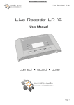
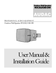
MTX48/88
User Manual
www.audac.eu
2
Index
Introduction
5
MTX Block Diagram
6
Precautions
7
Safety requirements Caution servicing
EC Declaration of Conformity Waste of Electrical and Electronic Equipment (WEEE)
Caution
Chapter 1: Pin connections and connectors Connection standards
Wire up the system
7
7
7
8
8
9
9
11
Chapter 2: Front & rear panel
Front panel overview
12
Chapter 3: MTX Quick start guide
Connecting the MTX
20
Chapter 4: User interface & configuration
Open the user interface
23
Front panel functions
Functions overview
Rear panel overview
Configuring the MTX
Ready
Login screen
Main screen
Zone settings
Input selection
Configuration settings screen
Paging volume
Priority settings
System configuration Mono / Stereo
Network settings
Password settings
Factory settings reset
iPhone + iPad
12
13
15
17
20
21
22
23
23
24
25
26
27
28
29
30
31
32
33
34
35
3
Chapter 5: Peripheral interfaces
Wall mounted control panels
36
Chapter 6: Additional information
IP Basics
46
4
MWX43/45 Basic wall panel
MWX65 All-in-one wall panel
WMI and WLI Wall Input units
MTX Wall Panel Connection possibilities
Paging
Peripheral connection limits
Updating the MTX
Technical specifications
Personal notes
37
37
39
40
41
43
45
46
47
48
49
Introduction
Multi-Zone Matrix
The MTX is AUDAC’s series of very cost efficient audio matrix systems for a wide range of
Multi-Zone audio applications, offering two different models with the same features and
possibilities, but with different zone capacities.
The MTX88 is the eight-zone version, and the MTX48 is the four-zone version. They both
contain two balanced microphone inputs with priority function, phantom power possibility
and three-band tone control.
Four stereo line-level inputs are provided to which any line-level music source such as a
CD-player, Tuner or MP3 player, ... can be connected. The other two inputs of the matrix
are the additional wall panel inputs for both line and microphone signals.
What makes the MTX system superior to all other matrix systems in their range, are the
advanced control possibilities. The MTX can be controlled by means of additional control
panels for every specific zone, with or without additional audio inputs. It also features a fully
functional web based interface that can be used to control and configure the audio system
with any device connected in your LAN network by just using a standard web browser, while
the apps for iPhone and iPad enable you to control the MTX out of your pocket. The RS232 port makes it possible to control it by means of any external equipment such as home &
industrial automation systems supporting RS232.
The front panel of the MTX contains for every zone a rotary push button with indication
LED’s whereby all the controls and settings can be done. A built-in PFL loudspeaker makes
it possible to pre-listen every channel without requiring a headphone.
The balanced line-level zone outputs are performed using 3-pin Euro-terminal block
connectors, each of them accompanied with an RJ45 connector for connecting additional
wall panels to that zone.
A 24 volts power connection makes it possible to keep the MTX running on emergency power,
even if the mains power is shut down.
MTX Block Diagram
Block diagram shown for MTX88 - 8 Zone Matrix
6
Precautions
READ FOLLOWING INSTRUCTIONS FOR YOUR OWN SAFETY
ALWAYS KEEP THESE INSTRUCTIONS. NEVER THROW THEM AWAY
ALWAYS HANDLE THIS UNIT WITH CARE
HEED ALL WARNINGS
FOLLOW ALL INSTRUCTIONS
NEVER EXPOSE THIS EQUIPMENT TO RAIN, MOISTURE, ANY DRIPPING OR SPLASHING
LIQUID. AND NEVER PLACE AN OBJECT FILLED WITH LIQUID ON TOP OF THIS DEVICE.
DO NOT INSTALL THIS UNIT NEAR ANY HEAT SOURCES SUCH AS RADIATORS OR
OTHER APPARATUS THAT PRODUCE HEAT
DO NOT PLACE THIS UNIT IN ENVIRONMENTS WHICH CONTAIN HIGH LEVELS OF DUST,
HEAT, MOISTURE OR VIBRATION
THIS UNIT IS DEVELOPED FOR INDOOR USE ONLY. DO NOT USE IT OUTDOORS
PLACE THE UNIT ON A STABLE BASE OR MOUNT IT IN A STABLE RACK
ONLY USE ATTACHMENTS & ACCESSORIES SPECIFIED BY THE MANUFACTURER
UNPLUG THIS APPARATUS DURING LIGHTNING STORMS OR WHEN UNUSED FOR LONG
PERIODS OF TIME
ONLY CONNECT THIS UNIT TO A MAINS SOCKET OUTLET WITH PROTECTIVE
EARTHING CONNECTION
CAUTION - SERVICING
This product contains no user serviceable parts. Refer all servicing to
qualified service personnel. Do not perform any servicing (unless you
are qualified to)
EC DECLARATION OF CONFORMITY
This product conforms to all the essential requirements and further
relevant specifications described in following directives: 2004/108/EC
(EMC) and 2006/95/EC (LVD)
7
WASTE ELECTRICAL AND ELECTRONIC EQUIPMENT (WEEE)
The WEEE marking indicates that this product should not be disposed
with regular houshold waste at the end of its working life. This regulation
is created to prevent any possible harm to the environment or human
health.
This product is developed and manufactured with high quality materials
and components which can be recycled and/or reused. Please dispose
this product to your local collection point or recycling centre for electrical
and electronic waste. This will make to sure that it will be recycled
on an environmentally friendly manner, and will help to protect the
environment in which we all live.
CAUTION
The symbols shown are internationally recognized symbols that warn about potentional
hazards of electrical products. The lightning flash with arrowpoint in an equilateral
triangle means that the unit contains dangerous voltages. The exclamation point in
an equilateral triangle indicates that it is necessary for the user to refer to the users
manual.
These symbols warn that there are no user serviceable parts inside the unit. Do not
open the unit. Do not attempt to service the unit yourself. Refer all servicing to qualified
personnel. Opening the chassis for any reason will void the manufacturer’s warranty. Do
not get the unit wet. If liquid is spilled on the unit, shut it off immediately and take it to a
dealer for service. Disconnect the unit during storms to prevent damage.
8
Chapter 1
Pin connections and connectors
CONNECTION STANDARDS
The in- and output connections for AUDAC audio equipment are performed corresponding
to international wiring standards for professional audio equipment.
Cinch (RCA):
For unbalanced line input connections
Tip: Signal White: Left Sleeve:
Red: Ground
Right
XLR:
For balanced microphone input connections
Pin 1: Ground
Pin 2: Signal +
Pin 3: Signal -
3-Pin Euro-Terminal Block:
For balanced line output connections
Left: Signal - Center:Signal + Right: Ground (XLR Pin 3)
(XLR Pin 2)
(XLR Pin 1)
9
RJ45 (RS485, Audio, +24V DC):
For connection to Wall Panels
Pin 1
Pin 2
Pin 3
Pin 4
Pin 5
Pin 6
Pin 7
Pin 8
White-Orange
Orange White-Green
Blue White-Blue
Green White-Brown
Brown AUDIO WLI & MWX65 +
AUDIO WLI & MWX65 +24V DC
RS485 A
RS485 B
GND
AUDIO WMI+
AUDIO WMI-
Not connected
Not connected
+24V DC
RS485 A
RS485 B
GND
AUDIO MIC+
AUDIO MIC-
RJ45 (RS485, Audio, +24V DC):
For connection to Paging console
Pin 1
Pin 2
Pin 3
Pin 4
Pin 5
Pin 6
Pin 7
Pin 8
White-Orange
Orange White-Green
Blue White-Blue
Green White-Brown
Brown ATTENTION
The twisted pair cabling must always be ‘straight’. In case of
self-made cabling it must be wired as described above, to ensure a proper functioning of the system.
RS232 (serial connection interface):
For connection with home automation systems, or other remote control equipment
Connection
PIN 2
PIN 3
PIN 5
Standard RS232
MTX TX
MTX RX
GND
Settings
19200 Baud
8 Bit
1 Stop bit
No parity
No Handshaking
RS232 / RS485 / TCP/IP
The MTX has RS232, RS485 and TCP/IP ports which all accept the same commands. The
complete command set to control the MTX is available in the MTX commands user manual
which is freely downloadable on www.audac.eu
10
Wire up the system
The wiring of the system must be done according to the following rules, to guarantee a
proper functioning of the system in all circumstances.
1.
2.
Wall Mounted Input & Control units:
MWX43/45
UTP/FTP Cat5e cable or better
MWX65
UTP/FTP Cat5e cable or better
MPX48/88
UTP/FTP Cat5e cable or better
3.
Ethernet connection: UTP/FTP Cat5e cable or better
Music sources and zone outputs: Must be connected with high-quality audio cable and high-quality connectors
11
Chapter 2
Front & rear panel
Front Panel overview
MTX48
Zone 1
VOLUME
INPU
BASS
REBLE
PFL
Zone 2
8
VOLUME
7
INPU
6
BASS
5
REBLE
4
Zone 3
8
VOLUME
7
INPU
6
BASS
5
REBLE
4
Zone 4
8
2
2
2
1
REBLE
4
3
1
BASS
5
3
PFL
INPU
6
3
PFL
VOLUME
7
1
PFL
8
6
5
4
3
2
PFL
ON
1
LEVEL
MTX88
Zone 1
VOLUME
INPU
BASS
REBLE
Zone 2
8
VOLUME
7
INPU
6
BASS
5
REBLE
4
2
1
VOLUME
7
INPU
6
BASS
5
REBLE
4
3
3
PFL
Zone 3
8
PFL
2
1
Zone 4
8
VOLUME
7
INPU
6
BASS
5
REBLE
4
3
PFL
2
1
Zone 5
8
VOLUME
7
INPU
6
BASS
5
REBLE
4
3
PFL
2
1
Zone 6
8
VOLUME
7
INPU
6
BASS
5
REBLE
4
3
PFL
2
1
Zone 7
8
VOLUME
7
INPU
6
BASS
5
REBLE
4
3
PFL
2
1
Zone 8
8
VOLUME
7
INPU
6
BASS
5
REBLE
4
3
PFL
2
1
PFL
8
POWER
MTX88
7
6
5
4
3
PFL
2
ON
1
LEVEL
The front panel of the MTX enables you to fully control and configure the settings of every
output zone. Every output zone contains its own specific control section, including one rotary
function dial, four function indication LED’s, and eight level / selection indication LED’s.
A built-in pre-listening loudspeaker makes it possible to pre-listen every output channel
without requiring an additional headphone. The channel which is currently playing through the
built-in pre-listening loudspeaker can be selected by means of the PFL selection switches
with which each zone control section is provided. The level of the PFL loudspeaker can be
controlled by using the PFL potentiometer.
On the right side there is a power button provided. Simply push this button to power-up
the system.
12
MTX48
7
POWER
Front Panel functions
The control section for every zone contains one rotary function dial, four function indication LED’s and eight level / selection indication LED’s.
Zone 1
Function
indication LED’s
VOLUME
INPUT
BASS
TREBLE
PFL Switch
8
7
6
5
Level / Selection
indication LED’s
4
3
PFL
2
1
Rotary
Function dial
By means of the function indication LED’s, the current operating function will be indicated.
The upper LED stands for volume adjustment, the second LED stands for input channel
selection, the third LED will blink when Bass tone adjustment is enabled, and the fourth
LED will blink when Treble tone adjustment is enabled.
The selection of which function has to be controlled can be done by pressing the rotary
function dial. When pressing the rotary function dial, the ‘Volume’ LED will illuminate.
Changing to the desired function can be done by rotating the function dial. The currently
set level / selection will appear when the function is selected. When any change needs to
be made to the level / selection, the rotary button should be pressed a second time. The
LED of the selected function will start blinking now, and any rotation to the function dial
will affect the set level / selection.
When the level / selection is changed to the desired level and any other change needs to
be made, you can return to function selection by pressing the rotary button again. The
settings menu will be quit automatically when the rotary dial is not operated for about 6
seconds.
Volume adjustment:
When no function is selected (MTX in idle status) and the function dial is rotated, the
volume adjustment function will be automatically activated. The volume LED will start
blinking and the current volume level will illuminate on the level / selection LED’s. Manual
switching to volume mode can also be done, by the procedure as described above. The
level / selection LED’s will indicate the currently set volume level. Only a few illuminated
LED’s correspond with a low volume level, and many illuminated LED’s correspond
with a high volume level. Rotating the rotary function dial in clockwise direction results
in an increasing volume level and rotating in counter-clockwise direction results in a
decreasing volume level.
Input selection:
The desired input channel for every zone can be selected. Every LED corresponds with
an input channel, and the corresponding LED for the selected input channel will illuminate
when selected. Switching between the different input channels can be done by rotating
the function dial. The tabel shown below gives an overview of which number corresponds
with which input channel.
13
Input number Corresponding channel
1
2
3
4
5
6
7
8
Microphone Input 1
Microphone Input 2
Line input 3
Line input 4
Line input 5
Line input 6
Line (WLI) + MWX65 Wall Panel Input
Microphone (WMI) Wall Panel Input
Bass and Treble adjustment:
The Bass and Treble adjustment can be done on a similar way. When the desired function is
selected, the corresponding function LED will start blinking. The adjustment can be done by rotating
the function dial. Similar to the volume adjustment, clockwise rotation results in a level increase
while counter-clockwise rotation results in a level decrease. When the level is set in neutral
position (0 dB), no LED’s of the level / selection LED’s will illuminate. When an amplification (dB +)
is selected, the upper four LED’s will illuminate from out the centre, depending on the selected level.
When an attenuation is selected (dB -), the lower four LED’s will illuminate from out the centre,
depending of the selected level.
PFL
MTX88
Built-in PFL
Loudspeaker
ON
PFL Level
Potentiometer
Power switch
LEVEL
POWER
Built-in PFL Loudspeaker and potentiometer:
The built-in pre-listening loudspeaker makes it possible to pre-listen every output channel without
the need for an additional headphone. The channel which is currently playing through the built-in
pre-listening loudspeaker can be selected by means of the PFL selection switches which are provided with each zone control section. The level of the PFL loudspeaker can be controlled by using
the PFL potentiometer.
Power switch:
By means of the power switch, the device can be turned ON and OFF. When the device is switched
on, the blue LED above the power button will illuminate.
14
Functions overview
Operation functions
Change
Volume
- Set function LED to ‘Volume’
- Push rotary dial once
- Rotate function dial to desired volume level
-> The indication LED’s show the selected volume level
- Push rotary dial once to return back to main menu
Change
Routing
- Set function LED to ‘Routing’
- Push rotary dial once
- Rotate function dial to desired input channel
-> The indication LED’s show the selected input channel (1-8)
- Push rotary dial once to return back to main menu
Change Bass
- Set function LED to ‘Bass’
- Push rotary dial once
- Rotate function dial to desired bass level
-> The indication LED’s show the selected level
- In neutal position, all LED’s are off
- Increased level causes upper LED’s to illuminate
- Decreased level causes lower LED’s to illuminate
- Push rotary dial once to return back to main menu
Change Treble
- Set function LED to ‘Treble’
- Push rotary dial once
- Rotate function dial to desired treble level
-> The indication LED’s show the selected level
- In neutal position, all LED’s are off
- Increased level causes upper LED’s to illuminate
- Decreased level causes lower LED’s to illuminate
- Push rotary dial once to return back to main menu
Pre-Fade
Listen
- Press PFL button
-> Selected channel now plays through the built-in loudspeaker
Save Settings
- Hold rotary button for Zone 1 and Zone 2 for 3 seconds
-> Saved settings will be recalled after MTX restart
15
Configuration functions
Priority 1
Enable /
Volume
(per zone)
Priority message from Microphone Input 1 will be announced to
priority enabled zones.
- Set LED for corresponding zone to ‘Volume’
- Hold rotary button for corresponding channel down for 3 seconds
(Volume LED starts blinking rapidly)
- Priority can be enabled and volume can be set by rotating the button (Priority is disabled when volume is set to zero)
- Press rotary button once again to return back to main menu
Priority 2
Enable /
Volume
(per zone)
Priority message from Microphone Input 2 will be announced to
priority enabled zones.
- Set LED for corresponding zone to ‘Routing’
- Hold rotary button for corresponding channel down for 3 seconds
(Routing LED starts blinking rapidly)
- Priority can be enabled and volume can be set by rotating the button (Priority is disabled when volume is set to zero)
- Press rotary button once again to return back to main menu
Paging Volume Paging volume for message from External Paging Console can be set.
- Set LED for corresponding zone to ‘Bass’
(per zone)
- Hold rotary button for corresponding channel down for 3 seconds
(Bass LED starts blinking)
- Paging volume can be set by rotating the button
(Paging is disabled when volume is set to zero)
- Press rotary button once again to return back to main menu
16
Mono / Stereo
output
(per zone)
Output signal for each zone can be switched between Mono and
Stereo
- While powering-up the device, hold the rotary buttonr for Zone 1.
The Mono / Stereo settings menu will be displayed
- Toggling between Stereo or Mono mode can be done by using each
zones’ rotary button
- LED 1: Zone set to Mono
- LED 2: Zone set to Stereo
- Power off and Power on the device again to go back to normal operation mode.
Set Wall Panel
Address
Connected wall panels can be assigned to one zone.
- Set LED for corresponding zone to ‘Treble’
- Hold rotary button for corresponding channel down for 3 seconds
(All connected wall panels will start blinking)
- Press upper button from the wall panel to assign this wall panel to the corresponding zone
- Repeat this action to assign multiple wall panels to this zone
Rear Panel overview
MTX48
MTX48
AUDAC
WP
PAGING
WP
WP
Caution Only use
fuses of the same type
WP
Warning Do not
expose this equipment
to ra n or moisture
LOW
-15
MD
+15
Line 6
GAIN
LL+
GND
LL+
GND
100-240V 50/60Hz
Fuse: T1AL/250V
LL+
GND
AC Input
LL+
GND
14
WP
WP
WP
WP
+9
Line 5
GAIN
14
CLIP
+9
Line 4
GAIN
14
CLIP
+9
LOW
HIGH
+15
GAIN
RR+
GND
RR+
GND
RR+
GND
ETHERNET
15
-15
+15
-15
MD
+15
Mic 2
Zone 4 Zone 3 Zone 2 Zone 1
RS 232
RR+
GND
GND
+24 V
W
Line 3
50
15
HIGH
+15
-15
+15
Mic 1
GAIN
PHANTOM
50
0
PHANTOM
0
GAIN
14
CLIP
+9
CL P
CLIP
CL P
MTX88
MTX88
AUDAC
PAGING
WP
WP
WP
WP
Caution Only use
fuses of the same type
Warning Do not
expose this equipment
to ra n or moisture
Line 6
RR+
GND
RR+
GND
RR+
GND
RR+
GND
RR+
GND
RR+
GND
ETHERNET
GAIN
LL+
GND
LL+
GND
LL+
GND
LL+
GND
LL+
GND
LL+
GND
LL+
GND
100-240V 50/60Hz
Fuse: T1AL/250V
LL+
GND
14
MD
+15
15
+9
CLIP
Line 5
GAIN
14
+9
CLIP
Line 4
GAIN
14
+9
CLIP
Line 3
LOW
HIGH
+15
-15
+15
-15
MD
+15
Mic 2
50
15
HIGH
+15
-15
+15
Mic 1
GAIN
PHANTOM
50
0
PHANTOM
0
GAIN
14
+9
CLIP
CL P
CL P
The rear side of the MTX contains all different kinds connectors which are necessary to
connect the device.
Power, RS232, Ethernet & Paging connectors:
MTX88
GND
AUDAC
+24 V
AC Input
LOW
-15
GAIN
Zone 8 Zone 7 Zone 6 Zone 5 Zone 4 Zone 3 Zone 2 Zone 1
RR+
GND
RS 232
RR+
GND
GND
+24 V
W
PAGING
RS 232
ETHERNET
AC Input
100 240V 50/60Hz
Fuse: T1AL/250V
Power inlet:
The mains power supply (110~240V AC / 50~60 Hz) has to be applied to this AC power
inlet. The connection is made by an IEC power connector and is fitted with a fuse. When
replacing the fuse, make sure that the value of the replacement fuse matches the value of
the original fuse. (T1AL/250V)
Emergency power inlet (24 Volt):
A 24 Volts emergency power supply can be connected to this 2-pin Terminal block
connector for keeping the MTX running on emergency power when the mains power is
shut down. When the MTX is running on 24 Volt emergency power, the function of the
power switch on the front panel is bypassed and can’t switch the MTX off.
17
RS232 Connection:
The RS232 connection can be used to control the MTX through external hardware such as
an home automation system or computer. Connect your external control hardware to this
port. The pinout and communication settings are described in an earlier chapter of this
user manual. The complete RS232 command instruction set and configuration information
can be downloaded from the AUDAC website.
Ethernet RJ45 Connector:
This connector should be connected to a LAN Network. This makes it possible to control
the MTX over Ethernet. The control can be done by sending commands over TCP/IP, by a
device with a standard webbrowser supporting flash or by using special apps which are
designed to be used in combination with mobile applications. (Smartphones & Tablets)For
more information about the Ethernet configuration of this device, check ‘Chapter 4: User
interface & Configuration’ and ‘Chapter 6: IP Basics’ of this user manual.
Paging RJ45 Connector:
The (optional) MPX paging consoles must be connected to the ‘PAGING’ RJ45 connector.
This allows to announce messages through the microphone of the paging console to all
the zones of the MTX. The selection of which announcements should be made in which
zone can be done on the control panel of the MPX paging consoles. (MPX48-4 zone for
MTX48 and MPX88-8 zone for MTX88)
Wall Panel & Zone output connectors:
WP
LL+
GND
RR+
GND
Zone 1
Wall Panel RJ45 Connectors:
Every zone has its specific Wall Panel (WP) RJ45 connector where to additional wall
panels can be connected. Every zone has the possibility to connect an additional Line and
Microphone input unit and multiple wall panel controllers. On these ports are both digital
RS485 control signals as well as differential audio signals transmitted.
Zone outputs (Terminal Block):
The zone outputs of the MTX are stereo (switcheable to mono) balanced line-level
outputs. Depending on the requirements for each specific application, the suitable
amplifiers should be connected to these output connectors. The used connectors are
3-pin Terminal-Block connectors.
18
Input connectors:
LOW
15
MID
+15
15
HIGH
+15
15
+15
Mic 2
GAIN
Line 3
50
PHANTOM
0
GAIN
14
+9
CLIP
CLIP
RCA / Cinch Line inputs:
Unbalanced Line-Level input sources (E.g. CD-Players, Tuners, MP3 Players, ... )
should be connected to the Line level inputs Line 3 to Line 6. These are standard linelevel stereo inputs performed with RCA connectors. All of them have a gain control
potentiometer whereby the level of the input signal can be controlled within a range of
-14 dB ~ +9 dB.
The clipping LED illuminates when the signal reaches the clipping level.
Balanced microphone inputs:
Balanced mono sources (E.g. Microphones) should be connected to inputs Mic 1 and Mic
2. Both channels are performed with Female XLR connector provided with gain control
potentiometer whereby the level of the input signal can be controlled within a range of
-50 dB ~ 0 dB. This makes it possible to connect both Line level input sources as well as
Microphone level input sources. The clipping LED illuminates when the signal reaches the
clipping level.
In addition, both channels have a three-band tone control whereby specific frequency
ranges can be adjusted within a range of ± 15 dB and a phantom power switch, whereby
the 15 Volts phantom power can be enabled for powering condenser microphones.
19
Chapter 3
MTX Quick start guide
This chapter guides you through the setup process of a basic project with one MTX audio
matrix and 8 standard MWX43/45 wall panels, two All-In-One MWX65 wall panels and some
regular Line & Microphone input sources.
Wall panels
A DA
A DA
+
+
+
+
+
+
+
+
-
-
-
-
-
-
-
-
+
+
+
+
-
-
-
-
P og
rog
Vol
MTX88
PAGING
WP
WP
WP
Pr g
+
WP
WP
WP
WP
Vol
-
-
C ut o : On y u e
us s of he s me t pe
WP
Line 6
G IN
L
L+
GND
L
L+
GND
L
L+
GND
L
L+
GND
L
L+
GND
L
L+
GND
L
L+
GND
4
L
L+
GND
LOW
15
MD
15
5
+
C IP
Line 5
G IN
4
+
C IP
Line 4
G IN
4
+
C IP
Line 3
OW
H GH
+15
15
15
5
ID
+15
Mc2
G IN
Zone 8 Zone 7 Zone 6 Zone 5 Zone 4 Zone 3 Zone 2 Zone 1
THERNET
AC nput
100 240V 5 /6 Hz
Fus : T1AL 25 V
+
Vol
-
Audio sources
P og
+
Vol
Wa n ng Do not
e po e th s e u pme t
o ra n o m i t re
RS 32
R
R+
GND
GND
+ 4V
AUDAC
Prog
V l
R
R+
GND
-
R
R+
GND
+
Vol
R
R+
GND
Prog
R
R+
GND
ol
R
R+
GND
rog
R
R+
GND
V l
R
R+
GND
P og
0
15
H GH
15
5
+ 5
Mc1
P ANT M
GA N
50
0
HA TOM
0
G IN
4
+
CL P
C IP
CL P
Amplifiers
Overview of the MTX setup
Connecting the MTX
ATTENTION
Make sure the power of the device is turned OFF before any connections or wiring
adjustments are made. When disregarding this rule, it can lead to permanent damage of
the equipment
1) Connecting audio sources
Connect all the Microphones to the XLR connectors on the rear side of the MTX. When
using condenser microphones, make sure the phantom power switch is turned ON.
Connect all the Line-Level audio sources (CD-Players, MP3 Players, Tuners, ... ) to the
RCA connectors on the rear side of the MTX. Adjust all input gains to the appropriate level
so no input clipping occurs.
2) Connecting amplifiers and/or speakers
Connect amplifiers (100V or Low impedance) to the balanced outputs of the MTX (Threepin Euro-Terminal Block). The amplifier configuration (100V or Low impedance) and power
needs to be chosen according to the requirements for each specific application. In its
standard configuration, the MTX has Balanced Stereo outputs, which can be switched to
Balanced Mono outputs. (See configuration functions)
20
3) Connecting wall panels
Connect the MWX43/45 and MWX65 wall panels to the Wall-Panel (WP) inputs (RJ45
connectors) for each zone. Multiple MWX43/45 wall panels can be connected to one
single WP input by using bus cabling (connecting all the wall panels in parallel). The
assignment of which wall panel is controlling which zone can be done by software
configuration (See configuration functions). Only one All-In-One Wall Panel with
additional audio input can be connected to one WP input.
4) Connecting a computer
A computer can be connected to the MTX through Ethernet. If the computer is directly
connected to the MTX, a crossed network cable is necessary. If the MTX is connected
to a local LAN network (connected to a router / switch / hub) a straight network cable is
necessary. Ask your IT administrator for help.
To get access to the user interface, enter the following address in your internet browser
address bar: “http://192.168.0.192” (This is the factory default IP address of the MTX, can
be changed in the user interface). The default administrator password (gives you access
to all functions) is “MTX” and the default user password (gives you only access to the
basic functions) is “user”. If you want to make any changes to the settings, you should
log-in with the administrator password.
Configuring the MTX
1) Changing the IP address
You can skip this step when the default IP address “192.168.0.192” is not used by another
device in your network, and is OK for you. If you like to change the IP address, go to
the “Setup” menu (click the icon in the upper right corner of the main screen) and click
“Network Settings”. Now you can change the IP address, and click “OK” to apply the
changes and save. Afterwards, your browser will be automatically redirected to the new IP
address of the MTX, and the default IP address is not longer valid.
2) Changing the password
You can skip this step if the default password “MTX” for administrator and “user” for
users is OK for you, buy we always recommend to change these passwords, especially
when your MTX is connected to a public network where external users have access to. If
you like to change the password, go to the “Setup” menu and click “Password settings”.
Here you can change the passwords. First, the old password needs to be entered, and
subsequently the new password needs to be entered twice (Max 8 characters). Press the
“OK” button to save the new password. Now, you always need to log-in with the new
passwords and the default passwords are not longer valid.
3) Configuring wall panels and sources
Go to the “Setup” menu and click “System configuration”. Now you have the possibility to
choose between “MWX65” and “MWX43/45”.
To configure the settings for the MWX43/45 wall panels, click the corresponding button.
By the dropdown list the zone can be chosen for which a wall panel should be assigned.
After the zone is selected, click the “Set Address” button. The displays on all connected
wall panels will start blinking with the selected zone number. Push the upper button
“Program +” on the wall panel which should be assigned with that particular zone. After
the “Program +” button is pressed, the wall panel will be linked with the selected zone
and the display will stop blinking. Repeat this action for all the connected wall panels and
for all zones untill a zone is assigned for every connected wall panel.
21
To configure the settings of the MWX65 wall panels, go back to the “Setup” > “System
configuration” menu, and click the “MWX65” button.
After this button is clicked, a window will be shown where all the configuration settings
for the MWX65 can be made. On the left side, a dropdown list is shown whereby the
address for the MWX65 can be selected. The address can be selected between “W001”
to “W008”. Logically it starts with the address “W001” for the first wall panel and
increases the address for every subsequent wall panel. After the desired address is
selected, click the “Set Address” button and the display on the MWX65 will start blinking.
Confirm the address of the wall panel by pushing the big rotary button on the wall panel
and the selected address will be assigned to the wall panel.
After this is done, the zone which should be controlled by this wall panel can be selected
by the dropdown list which is shown one position to the right.
The inputs which are selectable with the wall panel can be chosen in the “Selectable
inputs” dropdown list. After the inputs are clicked, all the selected inputs will appear in
the listbox shown below.
Certain actions such as Volume Change, Input change, Mute, Tone control and settings
can be disabled from the wall panel and the phantom power on the microphone input can
be enabled by clicking the check boxes.
Finally, the display backlight level and screensaver settings can be adjusted.
After all settings are done, click the “Save to Wallpanel” button and all your settings
will be send to the selected MWX65 wall panel. Repeat this action for all the connected
MWX65 Wall Panels.
Ready
Your system is now completely configured and ready to be used.
22
Chapter 4
User interface & configuration
To get access to the control and configuration settings, the MTX should be connected to a
computer or an Ethernet LAN network. For more information about network connections
and settings, see IP basics in chapter 8.
The standard (factory default) IP address of the MTX is 192.168.0.192, make sure this
address is within the IP range of the connected Ethernet LAN network (subnetmask
255.255.255.0). If the default network address is not within range of your LAN network,
contact your network specialist. The network address can be changed with the Standard
Web Based User Interface but therefore a network connection has to be made first!
Any device (PC, Laptop, PDA or even a Smartphone) with a web browser and the
Macromedia Flash 8.0 plug-in (or higher) installed, can be used to control the web based
user interface.
For mobile devices, such as PDA’s, smartphones or even iPhones or iPads, special
applications are developed to control the standard functions of the R2 Matrix.
Open the user interface
Start your default web browser and enter in the address bar the IP address of the embedded web
server of the MTX. (The factory default IP address is http://192.168.0.192).
Login screen
First the login screen will be displayed. A password should be entered to get access to the web interface of the MTX matrix.
There are two different access levels, administrator level and user level.
If you log-in using the administrator password, you get access to all functions and
configuration options of the MTX Matrix (The factory default password for administrator
acces is “MTX”).
When you log-in using the user password, you only get access to the basic functions of
the MTX matrix, such as changing the volume and changing the routing for a particular
output zone. (The factory default password for user acces is “user”).
After the right password is entered, click the “OK” button, and you will be redirected to
the main screen of the MTX interface.
NOTE
The passwords can be changed in the Configuration >> Password settings menu (Only
administrator)
23
MTX Login screen
Main screen
The main screen displays all the output zones with fader volume controls. (4 zones for
MTX48 and 8 zones for MTX88)
Volume control
The volume of each channel can be set by moving the fader of the corresponding channel
up or down. At the top and bottom side of each fader is a button with an arrow displayed
whereby the volume can be raised or lowered in steps of 1 dB. At the bottom is a “Mute”
button provided which mutes the volume of the corresponding output channel in one click.
After the volume is muted, this mute button will become Red, and the volume can be
unmuted after clicking it again.
Assign zone names
For a better overview of all output channels, every fader can be assigned by a specific
zone name as shown in following example. The name of the zone can be changed by
double clicking on the name which is displayed above the corresponding fader. When a
cursor comes up, remove the existing name with the backspace key, and just change the
name in the desired name. Click on the “Save Zone Settings” button and confirm to save
the changed zone settings. The name of the corresponding zone will be changed, and next
time you log in to the web based user interface, the same zone names will be displayed.
Connection status
In the top left corner of the window is the “Connection Status” displayed. To have
communication with the MTX, the connection status must be “ONLINE”. In normal
operation, the status “ONLINE” will be indicated in green. When the status “ONLINE” is
shown in orange, it means the communication with the matrix was interrupted but is
restored now. When the status “OFFLINE” is shown in red, it means there is currently no
communication with the matrix.
24
Input channel selection
The desired input signal for a particular zone can be selected by using the dropdown list
box below the zone name. This dropdown list shows the 8 input signals (in case all 8 are
enabled). When no input signal is selected, the option “Off” will appear.
Save
When any important changes are made, press the “Save” button in the top right corner.
When the settings are saved, it will be recalled after MTX restart.
Configuration menu
In the top right corner is a “Setup” button displayed. After clicking this button, you will be
redirected to the general configuration menu of the MTX.
MTX Main screen
Zone settings
After clicking on a “Settings” button for a specific zone, you will be redirected to the
“Zone Settings” window. This window gives an overview of all the settings that can be
applied to one specific zone.
Input selection
This window gives an overview of all channels which can be patched to that particular
zone output. The first displayed option is ‘No Input”, which means when this option is
selected, no input signal will be routed to that particular output zone. Below are all 8
inputs displayed which can be patched to that particular output zone.
Direct inputs
The first 6 displayed inputs are all direct inputs which are available on the back side of
the MTX. The first two are the microphone channels Mic 1 and Mic 2. The four next ones
are Line inputs LIne 3 to Line 6. These six ‘Direct Inputs’ are simultaneously available and
selecteable for all output zones of the MTX.
25
Wall panel inputs
The other two inputs (Inputs 7 and 8) are wall panel inputs. These input signals are
coming from external Wall Panel input devices, which are patched to the Wall Panel (WP)
RJ45 connectors on the MTX. These zone inputs are separately for every zone, and not
linkeable with other zones. Input 7 is the “MWX65/WLI” input, containing the signal
coming from external All-in-one (MWX65) or Line (WLI) input units. Input 8 is the “WMI”
input, containing the signal coming from external Microphone (WMI) input units.
Two-band tone control
On the right side of the window there are two faders displayed whereby the sound
settings can be adjusted through two-band tone control. The leftmost fader indicated
with “Bass” offers the possibility to adjust the level of the low frequencies, while the
rightmost fader indicated with “Treble” offers the possibility to adjust the level of the high
frequencies. The sound level level for both low and high tones can amplified or attenuated
between +14 dB and -14 dB. This can be easily done by sliding the faders up and down.
Assign input names
For a better overview of all the inputs, a name can be assigned to every specific input.
The name of the input can be changed by double clicking on the input name shown in
the “Zone Settings” screen. When a cursor comes up, remove the existing name with the
backspace key, and just change the name into the desired name. After the desired input
names are entered, they will be stored automatically when pushing the “Back” button and
will be recalled when reloading the MTX interface.
Input selection
In the “Input Selection” menu can be selected which inputs should be made available in
the “Quick Selection Menu” for this zone.
Back
Click the “Back” button to go back to the main window.
MTX Zone settings screen
26
Zone settings >> Input selection
The input selection window allows you to make a selection out of all available input
signals for the “Quick Selection Menu”. This menu is the dropdown list which is shown on
the main screen below the zone name, but also the inputs selecteable by the MWX43/45
wall panels are defined by the “Quick Selection Menu”.
Selection
This window gives an overview of 8 listboxes, one for every selecteable input channel.
In every listbox, the selection can be made between the “input name” and “Off”. When
switched to “Off”, the input channel is not selecteable for this zone.
Save
After the selection is made which inputs should be selecteable for this zone, click the ‘Set
inputs’ button and the selected inputs will be assigned with this zone.
Back
Click the “Back” button to go back to the previous window.
MTX Input selection screen
Configuration settings screen
The configuration settings control panel comes up after clicking the “Setup” button. This
button is always shown in the upper right corner of every window. (Only on Administrator level)
In this window, all the settings of the MTX can be made such as adjusting the network
settings, adjusting the paging settings, changing the priority settings, making the system
configuration for external connected devices, changing the password and restoring the
settings to factory default.
If you want to change some settings, just click on the corresponding icon.
27
Auto saving
All changes made to configuration settings will be saved automatically and are still
effective after shutdown of the device.
Back
Click the “Back” button to go back to the main screen.
MTX Configuration settings screen
Settings >> Paging Volume
In this window, the paging volume for each individual zone can be set by means of
the dropdown boxes. This part is more extensively described in “Chapter 5: Peripheral
interfaces >> Paging” of this user manual.
28
Settings >> Priority settings
The priority settings menu makes it possible to set the priority for direct microphone inputs
Mic 1 and Mic 2. When a microphone input has priority in a certain zone, all the other audio
sources will be suppressed for that zone when a signal is applied to one of the priority inputs.
Priority enabling / volume
This window shows an overview for both microphone channels Mic 1 and Mic 2 with
listboxes for every output zone of the MTX. With the listboxes, the priority can be enabled
and the level can be set.
Standard, all listboxes are switched to “Disabled”. When a microphone input should have priority in a certain zone, the condition should be
changed from “Disabled” to the desired level. The desired level can be selected by steps
of -1 dB in a range between 0 dB and -64 dB. When the level is set to 0 dB, the priority
messages for that zone will be announced on maximum volume.
The switching to and from a priority signal is done according to the HARDIN - FADEOUT
principle. This means when a priority situation occurs (signal present on the priority
inputs), immediately will be switched to this channel. When the priority situation is over
(no more signal present on the priority inputs), the status will return back to the initial
status by fading the sound in.
Click the “OK” button to confirm the priority settings.
MTX Priority settings screen
PRIORITY RANK
When a priority situation occurs and various priority enabled inputs are triggered at the
same time, the priority rank will be in following order:
1) Mic 1 input (Highest priority)
2) Mic 2 input
3) Paging input (Lowest priority)
29
Settings >> System configuration
In this window, the configuration settings for external connected devices such as wall
panels and paging consoles can be made. It shows three buttons, one for MWX43/45
whereby the configuration settings for the simple wall panel controller can be made, one
for MWX65 whereby the configuration settings for the All-In-One wall panel can be made
and one for paging whereby the configuration settings for APM and MPX paging consoles
can be made.
Just click the corresponding button to proceed to the desired settings menu.
For more information about the connection and configuration possibilities for external connected devices, refer to Chapter 5: Peripheral Interfaces of this user manual. In this chapter is extensively described how the connection and configuration for peripheral equipment should be done.
Back
Click the “Back” button to go back to the configuration screen.
MTX System configuration screen
Settings >> Front control settings
This window enables you to block certain settings from beïng accessible from the front
panel of the device. Four checkboxes are shown for the corresponding settings, indicating:
“Block volume change”, “Block input change”, “Block Bass / Treble change” and “Block
configuration settings”. By ticking the checkboxes the access to the corresponding settings
will be denied from the front panel. It is recommended disabling the configuration settings
from the front panel, when the device will be placed within reach of unqualified personel.
30
MTX Front control settings screen
Settings >> Mono/Stereo
In this window, the outputs of the MTX can be switched between Mono and Stereo. By
clicking the dropdown lists, the selection between Mono and Stereo will become visible.
When mono is selected, at both Left & Right outputs an identical signal will be present, which
is a mix of the left and right input signals.
MTX Mono / Stereo selection screen
31
Settings >> Network settings
In this window, the network settings of the MTX can be adjusted. The IP address can be set
manually or can be automatically assigned by a DHCP server.
The IP address is standard set to 192.168.0.192 and the subnetmask is standard set to
255.255.255.0.
Be aware:
When a DHCP server is used in the network, and the DHCP function of the MTX is
enabled, the DHCP server automatically assigns an IP address to the MTX.
In some cases this can cause problems because the IP address is not always known for the
user, and the IP address is required to access the web based user interface. If you don’t
know the IP address, the MTX will be lost in your network.
One additional problem is that, when the MTX boots the next time, the IP address that the
DHCP server assigns can be different.
The IP address can simply be changed by changing the value in the corresponding field.
After the IP address is changed, you will be automatically redirected to the newly changed
IP Address.
Click the “OK” button to confirm the network settings.
MTX Network settings screen
32
Settings >> Password settings
In this window the passwords for the MTX can be changed. There are two different password
levels. Administrator level which has full access to all functions and User level, which has
only access to the basic functions.
On the left side of the window the settings for the Administrator password can be changed,
while on the right side the settings for the User password can be changed.
For changing the password, enter the old password in the provided field, and enter the new
password twice in the provided fields. After this all is completed, push the “OK” button.
When the old password is correct, and the new password filled in both fields match, the
old password will be changed into the new password.
The factory default password for Administrator level is “MTX” and for User is “user”.
MTX Password settings
33
Settings >> Factory settings reset
ATTENTION
BE CAREFULL to press this button. It really will recall the ORIGINAL factory settings !!!
It does not recall the previously saved settings, but it recalls the original factory setting and
the previously made settings will be lost.
Click the “OK” button to reset the settings to factory default.
The following settings will return back to their default value: (Default value also shown below)
Main volume: -20 dB
Selected input: Input 1
Bass: 0 dB
Treble: 0 dB
Mute: Off
Priority 1: Disabled
Priority 2: Disabled
Paging volume: -10 dB
Adminstrator password: MTX
User password: user
Block front settings: All disabled
IP Address: 192.168.0.192
Subnetmask: 255.255.255.0
All inputs enabled in “Quick Selection Menu”
34
iPhone + iPad
The application which is available from the app store turns your
iPhone or iPad into a fully fledged audio matrix controller when using
it in combination with with the MTX. Simply connect it to your LAN
network by using a wireless access point, and after installing the app
on your mobile device, it is ready to be used.
To install the app on your mobile device, just tap the app store button
and download the ‘MTX Remote’ app by AUDAC on your mobile
device, or download the application from iTunes®. (If it’s downloaded
by iTunes, you first need to synchronise it before the ‘MTX Remote’
logo will appear on your display)
After the app is installed, make sure your mobile device is connected
to your wireless network and run the app by tapping the ‘MTX Remote’
app button. When starting-up, it will ask for the IP address of the
device where it should be connected to and the password should be
entered. The mobile applications only offers you the possibility to
change basic configuration settings like volume and routing control,
so the ‘Administrator’ and ‘User’ password both offer you the same
rights here.
After the password is entered, you will be redirected to the main
screen of the app, showing one fader for one specific zone. The
volume for this specific zone can be set by moving the fader up and
downwards and the input signal can be selected by tapping on the
input signals name. Then a list will be shown whereout the desired
input signal can be selected. The green button on the bottom can be
used to mute the volume for the corresponding zone, and will turn
red when the volume is muted. To switch between several output
zones, just sweep over your display from left to right, or right to left.
The iPad app is working similar and very intuitive just as the iPod
and iPhone app, the only difference is that multiple faders will be
shown besides or above each other. In horizontal position, all faders
will be shown next to each other, while in vertical position two rows
of faders will be shown above each other.
35
Chapter 5
Peripheral interfaces
The MTX offers the possibility to connect input and control units in addition to the
standard direct line and microphone inputs.
The connections of those additional units should be done to the Wall Panel (WP) or
PAGING inputs on the rear side of the MTX. Every zone has its own Wall Panel (WP) RJ45
connector. The wall control panels connected to these inputs can by assigned to any zone
and the signal applied to the wall panel inputs can be patched to the zone its connected
to.
Available peripheral devices for MTX:
MWX43/45 Basic wall panel with routing and volume control (WP)
The MWX43/45 are basic wall panels whereby the routing and volume for one specific
zone can be controlled. These wall panels can be connected in a bus structure,
connecting multiple MWX43/45 Wall panels to one WP input. The assignment of the wall
panel with a zone can be done by software assignment. (How this should be done is
described later in this chapter)
MWX65 All-In-One wall panel with graphic display, Line & Microphone input (WP)
The MWX65 wall panel can be used to control the volume and routing for one zone, but
also provides the possibility to control some additional functions like mute, tone control
and phantom power. But the greatest advantage of the MWX65 is that it contains an
additional Line and Microphone input which can be locally mixed and used as additional
ocal input for that zone on the MTX. The signal from the connected MWX65 is available
on Input 7 of the MTX.
Additional Line (WLI) and Microphone (WMI) input units (WP)
The Line and Microphone input units can be connected to the MTX to create additional
ocal Line and Microphone inputs for that particular zone. The signal coming from the local
Line input units (WLI) will be available on Input 7 and the signal coming from the local
Microphone input units (WMI) will be available on Input 8.
APM / MPX Paging consoles (PAGING)
The APM and MPX Paging systems can be used for paging to different zones of the MTX.
Depending on the number of zones of the MTX system (MTX48 or MTX88), associated
paging consoles are available for broadcasting to 4 or 8 zones. The paging consoles have
to be connected to the specially provided PAGING input and multiple paging consoles can
be linked in series, becoming a priority-based paging system.
Connection limitations
Please note that to every WP (Wall Panel) input, only two additional audio input devices
can be connected. One connected input device will be available on Input 7 (WLI or
MWX65) and one connected input device will be available on Input 8 (WMI). It is
impossible to connect multiple Line or Microphone input devices in series to one WP
input.
36
IMPORTANT
Always make sure the MTX is powered off when connecting or disconnecting devices to
the WP inputs.
Wall mounted control panels
The MTX installation can be expanded with additional wall control panels. Two kinds of
different wall panels are available. The MWX43/45 standard wall panel which allows to
adjust the routing and volume for one particular zone, and the MWX65 All-In-One wall
panel provides the possibility to connect an additional Line or Microphone signal source in
a specific zone.
+
Prog.
LINE IN
-
+
Vol
-
MIC IN
AUDAC
MWX43/45 (Left) & MWX65 (Right) Wall panels
These wall panels should be connected to the WP (Wall Panel) ports on the rear side of the
MTX with Twisted pair UTP Cat5e (or better) cabling. Multiple MWX43/45 wall panels can
be connected on one single WP (Up to 32 wall panels according to RS485 specification).
But only one All-In-One wall panel with audio inputs (MWX65) can be connected on one
single WP Port
MWX43/45 Basic wall panel
Functions
The MWX43/45 is the basic wall panel which allows you to control routing and volume for
one specific zone.
Change routing
The MWX43/45 display will indicate the current routing for the configured zone, by
displaying the number between 1 and 8 on the display. If the “Prog +” button is pressed,
the next input will be selected, if the “Prog -” button is pressed, the previous input will be
selected.
Change volume
The volume in the corresponding output zone can be changed by pressing the “Vol +”
and “Vol -” buttons. The volume will increase after pressing the “Vol +” button and will
decrease after pressing the “Vol -” button. When the volume is changed, the display will
indicate the currently set level for two seconds, and after those two seconds, the routing
will be displayed again.
37
Configuration
Before the MWX43/45 wall panels can be used, the wall panels needs to be assigned to
one particular zone. Perform the procedure described below to make sure this is done
correctly.
Go to the “Setup” menu and click “System configuration”. Then click the “MWX43/45”
button. A window with a dropdown list will be shown, showing all the output zones from
“Zone 1” to “Zone 8” (or “Zone 1” to “Zone 4” for MTX48). Select the zone whereto the
wall panel should be assigned, and click the “Set Address” button. The selected zone
number will start blinking on the display of the wall panels, and after pressing the upper
button on the desired wall panel, it will be assigned to the selected zone. Simply repeat
this action untill a zone is assigned for every connected wall panel.
MWX43/45 Settings screen
Maximum cable length
The maximum cable length depends of the number of connected wall panel. When only
one wall panel is connected, a maximum cable length of 600 meters can be reached. The
table below gives an overview of the maximum cable length, depending of the connected
wall panels.
38
No. of MWX43/45 Wall panels
Maximum cable length
1
2
3
4
5
6
7
8
600 meter
600 meter
400 meter
300 meter
200 meter
150 meter
120 meter
100 meter
MWX65 All-in-one wall panel
Functions
The MWX65 is the advanced All-in-one wall panel for the MTX. This wall panel has a
graphic display and can control the routing, volume, bass, treble and mute for one zone.
Besides those control functions, it also provides the possibility to connect a microphone
and a stereo line input source. The MWX65 wall panel should be connected to the WP
inputs of the MTX by using Cat5e (or better) cable.
The following functions of multiple zones of the MTX can be controlled:
- Volume within a range of 0 dB to -70 dB
- All inputs can be selected
- Mute can be activated
- Bass within a range from -14 dB to +14 dB
- Treble within a range from -14 dB to +14 dB
Configuration
Before the MWX65 can operate, the configuration should be made. First of all, an address
need to be assigned and the available inputs need to be defined.
Follow these steps to configure:
1) Go to the “Setup” menu and click “System configuration”. To configure the settings
for the MWX65 wall panels, click the corresponding button. After this button is clicked, a
window will be shown where all the configuration settings for the MWX65 can be made.
On the left side, a dropdown list is shown whereby the address for the MWX65 can be
selected. The address can be selected between “W001” to “W008”. Logically is started
with the address “W001” for the first wall panel and increases the address for every
subsequent wall panel. After the desired address is selected, click the “Set Address”
button and the display on the MWX65 will start blinking. Confirm the address of the wall
panel by pushing the big rotary button on the wall panel and the selected address will be
assigned to the wall panel.
2) The zone which should be controlled by this wall panel can be selected by the
dropdown list which is shown one position to the right.
3) The inputs which are selectable with the wall panel can be chosen in the “Selectable
inputs” dropdown list. After the inputs are clicked, they will appear in the listbox shown
below. They can be removed again from this listbox by selecting them, and clicking the
“Remove Input” button.
Those selectable inputs are not linked with the “Quick selection menu” like the inputs on
the MWX43/45 are.
4) Certain actions such as Volume Change, Input change, Mute, Tone control and settings
can be disabled from the wall panel by checking the checkboxes.
5) The microphone input has the possibility to provide +12V phantom power for powering
condenser microphones. The phantom power can be switched ON and OFF by clicking
the “Enable Mic Phantom” checkbox. This setting can also be changed in the MWX65
settings menu. (If “Block settings menu” is not checked)
6) The Backlight level, screensaver and screensaver delay can be set by means of three
dropdown boxes. This setting can also be changed in the MWX65 settings menu. (If
39
“Block settings menu” is not checked)
7) When the settings are made, press the “Save to Wallpanel” button and the settings will
be send to the selected MWX65 wall panel.
Previously made settings can be retrieved from the wall panel by clicking the “Load from
Wallpanel” button. Hereby, the settings which are stored in the wall panel will be displayed
in this window, making it possible to make any changes to the current settings.
MWX65 Settings screen
Maximum cable length for MWX65
The maximum cable length for the MWX65 wall panel is 300 meter.
WMI and WLI wall input units
Functions
The WLI and WMI units are wall input units which can be used as additional local inputs
for the MTX. They just can be plugged to the wall panel (WP) inputs on the rear side of the
MTX and no additional configuration settings have to be made. The wall panel inputs are
only available as input for the zone where its connected to.
WLI Line input (left) unit & WMI Microphone input unit (right)
The Line input units (WLI) are equipped with an RCA connector whereto any kind of
40
Line Level audio source can be connected, such as CD-Player, MP3-Player, Computer,
Laptop, ... The stereo signal is converted into a dual-mono signal and is transferred from
the input unit to the MTX in an analogue differential way which is insensitive for noise or
interferrence caused by external devices.
The Microphone input units (WMI) are equipped with a female XLR connector, whereto any
kind of balanced microphone can be connected. For powering condensor microphones, 12
Volt phantom power can be enabled by a jumper on the rear side of the unit. The signal
is transferred from the input unit to the MTX in an analogue differential way, which is
insensitive for noise and interference caused by external devices.
The signal coming from the line input unit will be available in input 7 of the corresponding
zone, and the signal coming from the microphone input unit will be available on input 8 of
the corresponding zone. Two input units (one WLI and one WMI) can be connected in bus
structure to one WP input. The inputs from the MWX65 and the inputs from the WLI are
both available on input 7. This means that only one of these inputs can be connected at a
time.
The connection of the WLI and WMI units should be done by using Cat5e (or better)
cabling and the maximum cable length to the MTX is 300 meter.
MTX Wall panel connection possibilities
This section provides an overview for the wall panel connection possibilities on the MTX.
In reality there are many more combinations possible than described here, but with these
few examples and the brief description it should be clear which connections solutions will
work and which solutions won’t work, and why.
Multiple MWX43/45 Wall panels can be connectTed on one Wall Panel Input. They can be configured to control all the same, or different zones.
+
+
-
-
Pr g
+
Vol
-
WP
WP
WP
WP
WP
WP
WP
Cau i n On y use
fu es of he same ype
WP
Warn ng Do not
exp se t is e ui m nt
to ain o m i tu e
15
MD
R
R+
GND
R
R+
GND
R
R+
GND
R
R+
GND
R
R+
GND
Line 5
GA N
G IN
9
4
CL P
L
L+
GND
L
L+
GND
L
L+
GND
L
L+
GND
L
L+
GND
L
L+
GND
L
L+
GND
L
L+
GND
14
Line 4
+15
+
5
15
15
15
15
MD
+15
Mic 2
Line 3
GA N
14
C IP
OW
H GH
G IN
Line 6
ETHERNET
AC nput
100 240V 50 60Hz
Fu e: T1AL 250V
OW
Zone 8 Zone 7 Zone 6 Zone 5 Zone 4 Zone 3 Zone 2 Zone 1
R
R+
GND
RS 232
R
R+
GND
GND
+24 V
AUDAC
PAGING
R
R+
GND
MTX88
0
Prog
+
+
+
-
-
-
+
+
+
Vol
Vol
V l
-
Prog
Pr g
rog
+
Vol
-
-
-
H GH
5
15
15
15
Mic 1
G IN
P ANTOM
0
0
P ANTOM
0
AIN
9
14
CL P
+
C IP
C IP
C IP
Multiple MWX43/45 and one MWX65 Wall panel can be connected on one Wall Panel Input
They can be configured to control all the same, or different zones. The audio input of the MWX65 can only
be routed to the zone its connected to.
+
+
+
+
-
-
-
-
Prog
+
Vol
-
Prog
+
Vol
-
P og
Prog
+
+
-
-
Vol
Vol
A DA
WP
WP
WP
WP
WP
WP
WP
Cau i n On y use
fu es of he same ype
WP
Warn ng Do ot
exp se t is eq ipm nt
to ain o m is u e
Line 6
R
R+
GND
R
R+
GND
R
R+
GND
R
R+
GND
R
R+
GND
ETHERNET
GA N
L
L+
GND
L
L+
GND
L
L+
GND
L
L+
GND
L
L+
GND
L
L+
GND
L
L+
GND
100 240V 50 60Hz
Fu e: T1AL 250V
L
L+
GND
14
AC nput
OW
15
MD
G IN
9
CL P
Line 5
4
+
C IP
Line 4
GA N
14
+15
5
15
15
15
Mic 2
0
15
MD
+15
5
H GH
15
15
15
Mic 1
P ANTOM
G IN
0
0
P ANTOM
0
G IN
9
CL P
Line 3
OW
H GH
G IN
Zone 8 Zone 7 Zone 6 Zone 5 Zone 4 Zone 3 Zone 2 Zone 1
R
R+
GND
RS 232
R
R+
GND
GND
+24 V
AUDAC
PAGING
R
R+
GND
MTX88
14
+
C IP
C IP
C IP
41
Multiple MWX65 Wall panel cannot be connected on one Wall Panel Input
A DA
A DA
PAG NG
WP
WP
WP
WP
WP
WP
WP
Cau on On y use
f ses of he s me ype
WP
LOW
War ing Do not
ex ose t is e ui m nt
to a n r moi tu e
R
R+
GND
R
R+
GND
R
R+
GND
R
R+
GND
R
R+
GND
Line 5
GA N
Line 4
AIN
9
14
CL P
L
L+
GND
L
L+
GND
L
L+
GND
L
L+
GND
L
L+
GND
L
L+
GND
L
L+
GND
L
L+
GND
14
1 0 24 V 50 60Hz
F se: T1AL 250V
MD
+ 5
15
5
4
15
15
MD
+ 5
15
5
15
Mic 1
G IN
HANT M
50
H GH
15
Mic 2
Line 3
GA N
+
C IP
LOW
H GH
15
G IN
Line 6
ETHERNET
AC Input
15
Zone 8 Zone 7 Zone 6 Zone 5 Zone 4 Zone 3 Zone 2 Zone 1
R
R+
GND
RS 232
R
R+
GND
+24 V
GND
AUDAC
R
R+
GND
MTX88
HANT M
50
0
0
GAIN
9
14
CL P
+
LP
C IP
LP
One Wall Line input (WLI) unit, one Wall Microphone input (WMI) unit and one (or mulltiple) MWX43/45 can
be connected on one Wall Panel Input. +
Prog
-
+
Vol
-
WP
WP
WP
WP
WP
WP
WP
Cau ion On y se
fu es of he same ype
WP
OW
W rn ng o ot
expo e th s eq ipme t
to r in or mo s u e
R
R+
GND
R
R+
GND
R
R+
GND
R
R+
GND
R
R+
GND
Line 5
GA N
GA N
+
4
CL P
L
L+
GND
L
L+
GND
L
L+
GND
L
L+
GND
L
L+
GND
L
L+
GND
L
L+
GND
L
L+
GND
14
Line 4
15
15
5
15
15
MID
15
+ 5
15
0
HI H
5
Mic 2
Line 3
GA N
+9
15
15
+ 5
Mic 1
GA N
PH NTOM
0
0
PH NTOM
0
G IN
14
9
CL P
OW
HI H
GA N
Line 6
ETHERNET
AC nput
100 240V 50 60Hz
Fus : T1AL 250V
MID
Zone 8 Zone 7 Zone 6 Zone 5 Zone 4 Zone 3 Zone 2 Zone 1
R
R+
GND
RS- 32
R
R+
GND
GND
+24 V
AUDAC
PAGING
R
R+
GND
MTX88
4
LP
9
C IP
CL P
C IP
One Wall Microphone input (WMI) unit and one MWX65 Wall Panel can be connected on one Wall Panel
Input. (The WMI audio input and MWX65 audio input are both using different pairs)
A DA
MTX88
AUDAC
PAG NG
WP
WP
WP
WP
WP
WP
WP
Ca t on On y use
uses o the s me ype
WP
R
R+
GND
R
R+
GND
R
R+
GND
R
R+
GND
R
R+
GND
R
R+
GND
R
R+
GND
Line 5
GA N
Line 4
GA N
+9
14
4
+15
5
15
15
MD
+ 5
Mic 2
50
H GH
15
+15
5
15
Mic 1
GAIN
PHAN OM
50
0
PHAN OM
0
GA N
+9
LP
LOW
H GH
15
Line 3
GA N
+
CL P
L
+
GND
L
+
GND
L
+
GND
L
+
GND
L
+
GND
L
+
GND
L
+
GND
L
+
GND
4
AC Input
MD
+ 5
GAIN
Line 6
ETHERNET
100 40V 5 /60Hz
Fuse: T1AL 250V
15
Zone 8 Zone 7 Zone 6 Zone 5 Zone 4 Zone 3 Zone 2 Zone 1
R
R+
GND
GND
+24 V
RS 232
LOW
Wa ni g Do not
e pose his qu pment
o a n or mo st re
W
14
+
CL P
CL P
LP
CL P
One Wall Microphone input (WMI), one Wall Line input (WLI) unit and one MWX65 Wall Panel cannot be
connected on one Wall Panel Input. (The WLI and MWX65 user the same pair, both input 7)
A DA
MTX88
AUDAC
PAG NG
WP
WP
WP
WP
WP
WP
WP
Cau on On y use
f ses of he s me ype
WP
R
R+
GND
R
R+
GND
R
R+
GND
R
R+
GND
R
R+
GND
R
R+
GND
R
R+
GND
Line 5
GA N
Line 4
AIN
9
14
CL P
L
+
GND
L
+
GND
L
+
GND
L
+
GND
L
+
GND
L
+
GND
L
L+
GND
L
L+
GND
4
1 0 2 0V 50 60Hz
F se: T1AL 250V
MD
+ 5
15
+
4
C IP
5
15
15
MD
+ 5
50
H GH
15
Mic 2
Line 3
GA N
LOW
H GH
15
G IN
Line 6
ETHERNET
AC Input
15
Zone 8 Zone 7 Zone 6 Zone 5 Zone 4 Zone 3 Zone 2 Zone 1
R
R+
GND
GND
+24 V
RS 232
LOW
War ing Do not
ex ose t is e ui m nt
to a n r moi tu e
W
15
5
15
Mic 1
G IN
HANT M
50
0
HANT M
0
GA N
9
14
CL P
+
LP
C IP
LP
Multiple Wall Line input (WLI) units cannot be connected on one Wall Panel Input. (They use the same pair,
both input 7)
PAG NG
WP
WP
WP
WP
WP
WP
WP
C ut on O ly u e
us s f t e ame ty e
WP
LOW
Wa n ng Do not
xpose h s equ pment
o ra n or mo s ure
MD
15
15
R
R+
GND
R
R+
GND
R
R+
GND
R
R+
GND
R
R+
GND
Line 6
Line 5
G IN
GA N
+
14
C IP
L
L+
GND
L
L+
GND
L
L+
GND
L
L+
GND
L
L+
GND
L
L+
GND
L
L+
GND
L
L+
GND
14
Line 4
Line 3
AIN
9
14
CL P
LOW
H GH
+ 5
15
5
+15
MD
15
15
Mic 2
50
H GH
+ 5
15
+15
Mic 1
GA N
ETHERNET
AC Input
100 240V 50/ 0Hz
Fuse: T AL/2 0V
5
Zone 8 Zone 7 Zone 6 Zone 5 Zone 4 Zone 3 Zone 2 Zone 1
R
R+
GND
RS-232
R
R+
GND
GND
+24 V
AUDAC
R
R+
GND
MTX88
GA N
PHA TOM
50
0
PHA TOM
0
GA N
+
4
C IP
9
CL P
CL P
CL P
Multiple Wall Microphone input (WMI) units cannot be connected on one Wall Panel Input. (They use the
same pair, both input 8)
MTX88
AUDAC
PAG NG
WP
WP
WP
WP
WP
WP
WP
C ut on O ly u e
us s f t e ame ty e
WP
Wa n ng Do not
xpose h s equ pment
o ra n or mo s ure
Line 6
R
R+
GND
R
R+
GND
R
R+
GND
R
R+
GND
R
R+
GND
R
R+
GND
ETHERNET
G IN
42
L
L+
GND
L
L+
GND
L
L+
GND
L
L+
GND
L
L+
GND
L
L+
GND
L
L+
GND
100 240V 50/ 0Hz
Fuse: T AL/2 0V
L
L+
GND
14
AC Input
LOW
5
MD
15
15
+
C IP
Line 5
Line 4
GA N
14
AIN
9
CL P
14
+
C IP
Line 3
50
LOW
H GH
+ 5
15
+15
Mic 2
GA N
Zone 8 Zone 7 Zone 6 Zone 5 Zone 4 Zone 3 Zone 2 Zone 1
R
R+
GND
RS-232
R
R+
GND
GND
+24 V
W
5
MD
15
15
H GH
+ 5
15
+15
Mic 1
PHA TOM
GA N
50
0
PHA TOM
0
GA N
14
9
CL P
CL P
CL P
Paging
Functions
The APM and MPX are optional paging systems which can be used for paging messages
to the different zones of the MTX. These paging systems contain a base with different
zone selection buttons. Depending of the number of zones (MTX48 or MTX88) associated
paging consoles with 4 and 8 buttons are available. Using the buttons on the base of the
paging consoles, zones can be selected whereto the paging announcements should be
made.
MTX88
AUDAC
PAGING
WP
WP
WP
WP
WP
WP
WP
Cau i n On y use
fu es of he same ype
WP
Warn ng Do ot
exp se t is eq ipm nt
to ain o m is u e
R
R+
GND
R
R+
GND
R
R+
GND
R
R+
GND
R
R+
GND
R
R+
GND
Line 6
GA N
Line 5
G IN
9
4
CL P
L
L+
GND
L
L+
GND
L
L+
GND
L
L+
GND
L
L+
GND
L
L+
GND
L
L+
GND
L
L+
GND
1
100 240V 50 60Hz
Fu e: T1AL 250V
MD
+15
5
+
Line 4
GA N
14
C IP
OW
H GH
15
15
15
15
MD
+15
Mic 2
GA N
ETHERNET
AC nput
OW
15
Zone 8 Zone 7 Zone 6 Zone 5 Zone 4 Zone 3 Zone 2 Zone 1
R
R+
GND
RS 32
R
R+
GND
GND
+ 4V
W
Line 3
0
5
H GH
15
15
15
Mic 1
GA N
P ANTOM
0
0
P ANTOM
0
G IN
9
14
CL P
+
C IP
C IP
C IP
Example of MTX Paging system with one paging console
In contrast to the wall panel connectivity whereby no multiple identical units on the same
databus may be connected, it is possible to connect multiple identical paging consoles
on the ‘PAGING’ databus. When multiple paging consoles are connected in parallel on the
‘PAGING’ databus, the paging will become priority based for wherefore addresses must be
assigned to every connected paging console.
PAGING
WP
WP
WP
WP
WP
WP
WP
Cau i n On y use
fu es of he same ype
WP
Warn ng Do ot
exp se t is eq ipm nt
to ain o m is u e
Line 6
R
R+
GND
R
R+
GND
R
R+
GND
R
R+
GND
R
R+
GND
ETHE NET
GA N
L
L+
GND
L
L+
GND
L
L+
GND
L
L+
GND
L
L+
GND
L
L+
GND
L
L+
GND
100 240V 50 60Hz
Fu e: T1AL 250V
L
L+
GND
14
AC nput
OW
15
MD
+15
5
G IN
9
CL P
Line 5
4
+
C IP
Line 4
GA N
14
15
15
0
15
MD
+15
5
H GH
15
15
15
Mic 1
P ANTOM
GA N
0
0
P ANTOM
0
G IN
9
CL P
Line 3
OW
H GH
15
Mic 2
GA N
Zone 8 Zone 7 Zone 6 Zone 5 Zone 4 Zone 3 Zone 2 Zone 1
R
R+
GND
RS 32
R
R+
GND
GND
+24 V
AUDAC
R
R+
GND
MTX88
14
+
C IP
C IP
C IP
Example of MTX Paging system with multiple paging consoles (Priority-based)
Configuration
To achieve a good operation of the paging system, some configuration settings have to
be made. For configuration, the paging consoles should be connected to the ‘PAGING’
databus and the configuration should be done through the web-based user interface of
the MTX. The paging configuration settings can be found in the “Setup” menu, under
“System configuration” and then the third button “APM1xx”. Follow the procedure below
to make your paging system work successfull.
43
The selected address is important to set the priorities when multiple paging consoles
are linked in parallell. The paging console with the lowest address number (001) will
have the highest priority in the system. When only one paging console is connected, it
is recommended to always assign the address ‘001’. When multiple paging consoles are
connected in parallel, the address ‘001’ should be assigned to the paging console with
highest priority, and all other connected paging consoles should get increasing addresses
in order of priority.
Select the address by the dropdown box, and click the “Set Address” button. Now the
lights on all the connected paging consoles will start blinking. After pushing the “PTT”
(Push to Talk) button, the selected address will be assigned to the paging console which
has been operated.
After the address has been assigned, the button “Configure APM” must be clicked and all
configuration data will be transferred and stored inside the paging console.
Repeat this procedure for every connected paging console with different addresses in
order of priority.
On the right side of this screen, the ratio between the speech and chime signal can be set.
When both speech and chime should be announced at maximum volume, both dropdown
lists should be set to ‘-0dB’. If the chime has to be announced louder than the speech
or vice versa, this ratio can be adjusted by the dropdown lists in a range between -0dB
and -48 dB. The general paging volume for each zone (both chime and speech) will be
dominated by the general paging volume settings, described later in this chapter.
MTX Paging configuration screen
Paging volume
The paging volume for each individual zone can be set in the “Setup” menu under “Paging
volume”. The volume can be set by means of the dropdown boxes displayed next to the
zone names. The paging volume can be set in steps of -1 dB, starting by 0 dB, going to
-∞. When the volume is set to 0 dB, announcements for the corresponding zone will be
made on maximum volume.
44
Peripheral connection limits
The number of peripheral devices which can be connected to the MTX is depending of the
current which should be delivered from the MTX side. Every peripheral device connected
to the MTX has a certain power consumption which must be taken into account. The total
current which should be delivered from the MTX side may never exceed the 1.5 Ampere
limit. This includes the current for all wall panel inputs for every zone added with the
current of the devices connected to the PAGING input. The table shown below gives an
overview of the current consumption for every device which can be connected to the MTX.
Peripheral device
Current consumption
WLI Wall Line input
WMI Wall Microphone input
MWX43/45 Wall panel
MWX65 All In One Wall panel
MPX48 Paging console
MPX88 Paging console
40 mA
40 mA
14 mA
75 mA
75 mA
75 mA
ATTENTION
Make sure the current consumption of all connected
peripheral devices added together never exceeds the 1.5
Ampere limit
45
Chapter 6
Additional information
IP Basics
Many AUDAC products are controllable by Ethernet. The Ethernet connection which is used
on the AUDAC products is TCP/IP based like 99% of the computer networks. There are some
basics which you need to know to successfully make a TCP/IP Ethernet connection.
The data in TCP/IP networks is always send in packages, all these packages must be delivered
at an unique address, just like the mailman delivers mail at your home mailbox. In TCP/IP
networks, this address is called the “IP address”. The IP address is always a number in the
following format “192.168.000.001”. As you can see, this address consists of 4 separate
numbers ranging from “000” to “255”.
In simple terms, only the latest number of an IP address can be different within a network,
so there is a maximum of 256 unique addresses within a network, ranging from “xxx.
xxx.xxx.000” to “xxx.xxx.xxx.255”. The first three numbers must be the same to make
communication between several devices possible, else the devices can not communicate
with each other.
Example:
Device 1:
IP address:
192.168.000.001
Device 2:
IP address:
192.168.000.002
Device 3:
IP address:
192.168.001.003
In this example, Device 1 can communicate with Device 2, but not with Device 3, because
the first three numbers must be the same. These first three parts are called the “IP
range”, so the devices must be in the same “IP range” to communicate with each other.
The “IP range” of home and office networks are defined by the network administrator,
this means that the IP range of your home or office network can be different from another
network. AUDAC products have the following IP address as default: “192.168.0.xxx”, this means
the standard IP range of AUDAC products is “192.168.000.xxx”. If your network is using
a different IP range, the AUDAC products will not be accessible from your network. You
can change the IP address of the AUDAC products to make them work properly in your
network. This can be done in the settings menu, and is described extensively in the
“Settings” chapter of this user manual.
Of course, to make changes to the settings menu of the AUDAC products, you must have
access to the user interface on the products webpage. This can be done by temporarily
giving your computer an IP address within the IP range of the AUDAC product, for
example “192.168.0.200”. After the IP address of your computer is within the IP range
of the product, the user interface is accessible and the IP address of the product can be
changed to an IP address within the IP range of your network. If the IP address of the
product is within the IP range of your network, you can change the IP address of your
computer again to it’s former IP address and the product should work properly in your
home or office network.
46
Ask your network administrator for help if you are not familiar with networks.
Summary
- All devices must have an unique IP address
- All devices must be within the same IP range
Updating the MTX
TCP/IP
Updating of the MTX can be done by using the TCP/IP Protocol. Simply connect the MTX
to your LAN network and both updates for firmware and website can be done from every
computer connected in your LAN network.
For more information about the latest available updates and the step by step procedure
how this software update should be performed, please check our website.
The latest information about the available updates will always appear on the website.
47
Technical specifications
Inputs
48
2 x Balanced Microphone (Female XLR)
4 x Stereo unbalanced Line (RCA)
8 x Wall Panel Input (RJ45)
1 x Paging Input (RJ45)
Outputs
8 x Stereo Balanced Line (3-pin Euro Terminal Block ~ 3.81 mm)
Microphone inputs
Connectors
Sensitivity
EQ Input
High (12.5 kHz)
Mid (2.5 kHz)
Low (80 Hz)
Phantom power
Female XLR 0 dB ~ -50 dB
±15 dB
±15 dB
±15 dB
15 V DC
Line inputs
Connectors
Sensitivity
RCA
-14 dB ~ 9 dB
Outputs
Connectors
Impedance
Output level
EQ Output
Treble (2.5~20kHz)
Bass (100 Hz)
3-Pin Euro Terminal Block (3.81 mm)
51 Ohm
- 70 dB ~ 0 dB
±14 dB
±14 dB
Frequency response
20 Hz - 20 kHz
Signal / Noise ratio
Mic
Line
> 80 dB
> 100 dB
THD + N
Mic
Line
< 0.05 dB
< 0.01 dB
Crosstalk - 85 dB
Control possibilities
Front panel
RS232
Wall Panels (RS485)
iPhone / iPad
TCP/IP (Integrated webserver)
Power supply Mains power Emergency power
100 ~ 240 V AC / 50 ~ 60 Hz
24 V DC
Power consumption
MTX48
MTX88
9 Watt
12 Watt
Weight MTX48
MTX88
6.24 Kg
6.38 Kg
Dimensions (W x H x D) 482 x 88 x 335 mm
Unit height
2HE
Notes
49
Notes
50
Notes
51
Notes
52