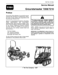
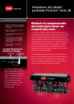
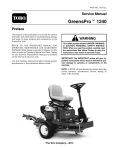
1
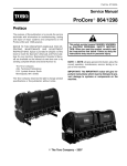
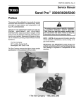
Engine Installation (Fig. 11)
1. Position machine on a level surface. Make sure that
spark plug wires are not connected to engine spark
plugs.
2. Make sure that all parts removed from the engine
during maintenance or rebuilding are properly installed
to the engine.
IMPORTANT: Make sure to not damage the engine,
fuel hoses, electrical harness or other parts while
installing the engine.
3. Carefully position engine on machine frame.
4. Install cap screws with washers through the inner engine mounting holes and frame. Install flat washer and
lock nut on cap screws. Do not fully tighten lock nuts at
this time.
A. Make sure that negative battery cable, wire harness ground wire and internal lock washer are
installed with the front, left corner screw (Fig 12).
B. The rear, left corner screw should be installed up
through frame and engine. The other three (3)
screws should be installed down through engine and
frame.
5. If centrifugal clutch was removed from crankshaft,
install clutch (see Centrifugal Clutch Installation in this
section).
6. Install drive belts to centrifugal clutch and jack shaft
pulley. Make sure that belts are properly positioned in
driven pulley on jack shaft.
7. Using a straight edge across the lower face of the
centrifugal clutch pulley, verify drive belt alignment
across clutch and jack shaft driven pulleys. Adjust position of engine so that drive belt and straight edge are
aligned indicating correct position of engine. Once the
pulleys are aligned, fully tighten the engine mounting
fasteners. Torque fasteners from 270 to 330 in--lb (31
to 37 N--m).
9. Make sure that tinnerman nuts (items 23 and 40) are
correctly positioned at frame brackets.
10.Install muffler guard, belt guard and belt cover (see
Drive Belt Covers in the Service and Repairs section of
Chapter 6 -- Chassis). Make sure that fuel line is not
pinched between belt guard and machine frame.
11. Plug engine electrical harness connector into machine wire harness (Fig. 13).
12.Connect positive cable and fusible link to starter motor (Fig. 13).
13.Connect wire harness connector to ignition switch on
engine.
14.Position wire harness under harness clamp on engine and secure in place with screw (Fig. 13).
15.Remove plug installed in fuel hose during engine removal process. Connect fuel hose to the fuel filter inlet
and secure with hose clamp (Fig 12).
IMPORTANT: Any leaks in the air filter system will
allow dirt into engine and will cause serious engine
damage. Make sure that all air cleaner components
are in good condition and are properly secured during engine installation.
16.If removed, install air cleaner assembly (see Air
Cleaner Installation in this section).
17.Check and adjust engine oil level as needed.
18.Connect cables to the battery terminals. Connect
positive battery cable first and then the negative cable.
Tighten nuts that secure battery cables from 10 to 15 ft-lb (14 to 20 N--m).
19.Attach spark plug wires to the spark plugs.
2
1
8. Adjust drive belt idler pulley to achieve proper belt
tension (see Operator’s Manual).
IMPORTANT: After adjusting belt tension, check
that distance from idler pulley face to the faces of
the clutch drive pulley and jack shaft driven pulley
is correct (Fig. 14). This distance is necessary to ensure that idler pulley is correctly aligned to drive
belts. If necessary, re--adjust positions of drive and
driven pulleys to allow correct distance (see Jack
Shaft Assembly in the Service and Repairs section
of Chapter 6 -- Chassis).
Engine
3
FRONT
0.330” (8.4 mm)
Idler Face to Sheave Face
Figure 14
1. Jack shaft
2. Centrifugal clutch
Page 3 -- 14
3. Idler pulley
ProCore Processor