1
LUDLUM MODEL 375
WEBPAGE AND SUPERVISOR SERVICE
SOFTWARE MANUAL
April 2014
Version 1.6.9
LUDLUM MODEL 375
WEBPAGE AND SUPERVISOR SERVICE
SOFTWARE MANUAL
April 2014
Version 1.6.9
LUDLUM MEASUREMENTS, INC.
501 OAK STREET, P.O. BOX 810
SWEETWATER, TEXAS 79556
325-235-5494, FAX: 325-235-4672
Table of Contents
INTRODUCTION .......................................................................................................................................................1
MODEL 375 SUPERVISOR SERVICE ..............................................................................................................................1
ASP WEB APPLICATION ..............................................................................................................................................2
DEVICE FINDER ...........................................................................................................................................................2
SERVICE UTILITY ........................................................................................................................................................2
AREA MONITOR UTILITY ............................................................................................................................................2
SOFTWARE LICENSE AGREEMENT ...................................................................................................................3
GETTING STARTED .................................................................................................................................................6
MINIMUM REQUIREMENTS – WINDOWS XP ................................................................................................................6
MINIMUM REQUIREMENTS – WINDOWS VISTA ...........................................................................................................7
MINIMUM REQUIREMENTS – WINDOWS 7 ...................................................................................................................7
MINIMUM REQUIREMENTS – WINDOWS SERVER 2003 ................................................................................................8
MINIMUM REQUIREMENTS – WINDOWS SERVER 2008 ................................................................................................8
INSTALLATION OVERVIEW – SINGLE SERVER .............................................................................................................9
INSTALLATION OVERVIEW - MULTIPLE SERVERS...................................................................................................... 11
UPGRADING AN EXISTING WEB PAGE AND SUPERVISOR SERVICE INSTALLATION – WINDOWS XP .......................... 14
UPGRADING AN EXISTING WEB PAGE AND SUPERVISOR SERVICE INSTALLATION – WINDOWS VISTA ..................... 15
UPGRADING AN EXISTING WEB PAGE AND SUPERVISOR SERVICE INSTALLATION – WINDOWS 7 ............................. 17
UPGRADING AN EXISTING WEB PAGE AND SUPERVISOR SERVICE INSTALLATION – WINDOWS SERVER 2008 .......... 18
UPGRADING AN EXISTING WEB PAGE AND SUPERVISOR SERVICE INSTALLATION – WINDOWS SERVER 2003 .......... 21
COMPLETING THE WEB PAGE AND SUPERVISOR
SERVICE UPGRADE ............................................................ 21
IIS INSTALLATION ................................................................................................................................................ 27
IIS SERVER INSTALLATION – WINDOWS XP ............................................................................................................. 27
IIS SERVER INSTALLATION – WINDOWS VISTA......................................................................................................... 29
IIS SERVER INSTALLATION – WINDOWS 7................................................................................................................. 32
IIS SERVER INSTALLATION – WINDOWS SERVER 2008 ............................................................................................. 36
IIS SERVER INSTALLATION – WINDOWS SERVER 2003 ............................................................................................. 42
.NET 4.0 INSTALLATION ...................................................................................................................................... 45
SQL SERVER INSTALLATION ............................................................................................................................ 46
WEB PAGE AND SUPERVISOR SERVICE INSTALLATION ......................................................................... 52
CONFIGURING SQL SERVER MANUALLY (OPTIONAL) ............................................................................................... 59
CONFIGURING INTERNET INFORMATION SERVICES MANUALLY (OPTIONAL) ............................................................ 66
Configuring IIS in Windows XP ............................................................................................................................ 66
Configuring IIS in Windows Vista ......................................................................................................................... 70
Configuring IIS in Windows 7 ............................................................................................................................... 73
Configuring IIS in Windows Server 2008 .............................................................................................................. 77
Configuring IIS in Windows Server 2003 .............................................................................................................. 81
TESTING THE WEB SERVER ....................................................................................................................................... 87
CONFIGURATION OF AREA MONITORS AND CAMERAS .......................................................................... 88
CONFIGURING THE MODEL 375 AREA MONITOR....................................................................................................... 88
Configuring Network Settings – Web Interface (firmware versions N12 and later) ............................................. 89
Configuring Network Settings – Setup Utility (firmware versions 39801N11 and earlier) ................................... 91
Network Settings .................................................................................................................................................... 93
Camera Settings .................................................................................................................................................... 93
Service Utility ........................................................................................................................................................ 94
Supervisor Settings ................................................................................................................................................ 95
ADDING AREA MONITORS TO THE SERVICE .............................................................................................................. 96
MODIFYING AND DELETING AREA MONITORS .......................................................................................................... 96
CREATING A BACKUP OF THE CONFIGURATION FILE ................................................................................................. 96
EMAIL SETTINGS ....................................................................................................................................................... 97
DATABASE SETTINGS ................................................................................................................................................ 98
USER-DEFINED FIELDS .............................................................................................................................................. 99
LOCATION MAP ....................................................................................................................................................... 100
UPDATING MODEL 375 ETHERNET BOARD FIRMWARE USING FTP ........................................................................ 100
OPERATION ........................................................................................................................................................... 102
E-MAIL ................................................................................................................................................................... 102
DATA LOGGING ....................................................................................................................................................... 102
EVENT LOG ............................................................................................................................................................. 103
WEB INTERFACE ..................................................................................................................................................... 103
CURRENT STATUS PAGE .......................................................................................................................................... 103
TIMELINE DATA PAGE............................................................................................................................................. 105
FLOOR PLAN STATUS PAGE ..................................................................................................................................... 112
ETHERNET INFORMATION .............................................................................................................................. 113
IP ADDRESSES ......................................................................................................................................................... 113
ETHERNET CABLE TERMINATION ............................................................................................................................ 113
TROUBLESHOOTING .......................................................................................................................................... 116
TROUBLESHOOTING THE AREA MONITOR ............................................................................................................... 116
ETHERNET OUTPUT ................................................................................................................................................. 116
FIREWALLS.............................................................................................................................................................. 117
ETHERNET STATUS LIGHTS ..................................................................................................................................... 117
TROUBLESHOOTING THE NETWORK ........................................................................................................................ 117
Unable to Configure Network Settings ................................................................................................................ 117
Area Monitors Report as Missing........................................................................................................................ 119
TROUBLESHOOTING THE SUPERVISOR SERVICE ...................................................................................................... 119
TROUBLESHOOTING THE MODEL 375 WEB PAGE .................................................................................................... 125
Error 404 or 404.2 .............................................................................................................................................. 125
Web Page does not load ...................................................................................................................................... 125
Directory Listing Denied ..................................................................................................................................... 126
Invalid object name “area_monitor” .................................................................................................................. 126
Login failed for user “xxxxxx” ............................................................................................................................ 126
Default Web Site Won’t Start – Unexpected Error 0x8ffe2740 occurred ............................................................ 127
Could not load file or assembly ‘App_Licenses’ or one of its dependencies. The module was expected to contain
an assembly manifest. .......................................................................................................................................... 128
Current Status page shows no area monitors...................................................................................................... 128
Current Status page shows area monitor(s) with a status of “Missing”. ............................................................ 128
TROUBLESHOOTING FTP FIRMWARE UPDATES ....................................................................................................... 128
REPLACING RABBIT ETHERNET BOARDS................................................................................................................. 129
Model 375 Webpage and Supervisor Service
1
Section
Software Manual
Introduction
The Ludlum Model 375 Webpage and Supervisor Service is a radiation network
software package that collects and displays radiation levels and alarm status from
up to fifty Model 375 series area monitors. The Ludlum Model 375 is a wallmount digital area monitor that can be equipped with an Ethernet interface.
Some area monitors such as the 375-10 have Ethernet built in while others can
be updated using an Ethernet kit. The Ethernet kit can be installed by the
customer or the area monitors can be sent back to LMI for installation. Using
this interface, radiation data may be placed onto the Ethernet network for realtime monitoring, email alerts, and stored into a database for later analysis.
With the Ethernet interface, the area monitor can be connected to the network
allowing for real time monitoring of radiation data, email alerts, and database
logging. A standard web browser is used to view the current status and query
the data.
The Webpage and Supervisor Service software includes the following
components:
Model 375 Supervisor Service
ASP Web Application
Device Finder
Service Utility
Area Monitor Utility
Model 375 Supervisor Service
The Supervisor is a Windows™ service that listens for connections from the
area monitors. Once a connection is made, the Supervisor collects and
processes the data. Data is logged into a SQL database and can be optionally
configured to save data into a comma separated (.CSV) text file. The Supervisor
also sends E-Mails when an alarm or failure occurs. The Supervisor currently
supports a maximum of 50 area monitors.
Ludlum Measurements, Inc.
Page 1
April 2014
Model 375 Webpage and Supervisor Service
Software Manual
ASP Web Application
Hosted on Internet Information Service (IIS), the ASP.NET application
provides a web interface to view the current status of each area monitor from
any computer that has access to the web server. A floor plan view displays the
current status of each instrument overlayed on top of an image of the building's
layout. Also available are the incident summary and timeline data for each area
monitor. Ten user-defined fields are available to enter comments about the
recorded incidents. Comments can be added by clicking on the View button
next to each incident.
Device Finder
The Device Finder application is used to search the network for any area
monitors and display the IP Address and firmware version. Because the Device
Finder application uses UDP to discover the area monitors, search results will
typically be limited to the local subnet.
Service Utility
The Service Utility is used to add and remove area monitors, configure E-Mail
settings, and to configure the SQL server database.
Area Monitor Utility
There are currently two Ethernet firmware versions available. Version
39801N10 requires the Area Monitor Utility to configure the Ethernet settings.
The Ethernet settings of version 39801N12 and later are configured by entering
the Area Monitor's IP address in a web browser.
Radiation data is logged into a Microsoft SQL Server database at user-defined
intervals. The Supervisor service supports SQL Server 2005 and later and will
also work with the free Express edition. SQL Server 2008 Express is included
on the installation CD. Data is logged for each area monitor at two different
intervals depending on the status. The normal logging interval is used when the
status of the area monitor is OK. The alarm logging interval is used when the
area monitor is alarming or has failed. Two intervals allow more data to be
collected during an alarm or failure.
The area monitors can be grouped using several fields to aid in management.
These fields are:
Site
Building
Area
Location
Ludlum Measurements, Inc.
Page 2
April 2014
Model 375 Webpage and Supervisor Service
2
Section
Software Manual
Software License Agreement
BY INSTALLING THIS SOFTWARE, YOU ARE CONSENTING TO BE
BOUND BY THIS AGREEMENT. IF YOU DO NOT AGREE TO ALL OF THE
TERMS OF THIS AGREEMENT, DO NOT INSTALL THE PRODUCT.
Single User License Grant: Ludlum Measurements, Inc. ("Ludlum") and its
suppliers grant to Customer ("Customer") a nonexclusive and nontransferable
license to use the Ludlum software ("Software") in object code form solely on a
single central processing unit owned or leased by Customer or otherwise
embedded in equipment provided by Ludlum.
Customer may make one (1) archival copy of the Software provided Customer
affixes to such copy all copyright, confidentiality, and proprietary notices that
appear on the original.
EXCEPT AS EXPRESSLY AUTHORIZED ABOVE, CUSTOMER SHALL NOT:
COPY, IN WHOLE OR IN PART, SOFTWARE OR DOCUMENTATION;
MODIFY THE SOFTWARE; REVERSE COMPILE OR REVERSE ASSEMBLE
ALL OR ANY
PORTION OF THE SOFTWARE; OR RENT, LEASE,
DISTRIBUTE, SELL, OR
CREATE DERIVATIVE WORKS OF THE
SOFTWARE.
Customer agrees that aspects of the licensed materials, including the specific
design and
structure of individual programs, constitute trade secrets and/or copyrighted
material of Ludlum. Customer agrees not to disclose, provide, or otherwise
make available such trade secrets or copyrighted material in any form to any
third party without the prior written consent of Ludlum. Customer agrees to
implement reasonable security measures to protect such trade secrets and
copyrighted material. Title to Software and documentation shall remain solely
with Ludlum.
LIMITED WARRANTY. Ludlum warrants that for a period of ninety (90) days
from the date of shipment from Ludlum: (i) the media on which the Software is
furnished will be free of defects in materials and workmanship under normal
use; and (ii) the Software substantially conforms to its published specifications.
Except for the foregoing, the Software is provided AS IS. This limited warranty
extends only to Customer as the original licensee. Customer's exclusive remedy
and the entire liability of Ludlum and its suppliers under this limited warranty will
be, at Ludlum or its service center's option, repair, replacement, or refund of the
Software if reported (or, upon request, returned) to the party supplying the
Software to Customer. In no event does Ludlum warrant that the Software is
Ludlum Measurements, Inc.
Page 3
April 2014
Model 375 Webpage and Supervisor Service
Software Manual
error free or that Customer will be able to operate the Software without
problems or interruptions.
This warranty does not apply if the software (a) has been altered, except by
Ludlum, (b) has not been installed, operated, repaired, or maintained in
accordance with instructions supplied by Ludlum, (c) has been subjected to
abnormal physical or electrical stress, misuse, negligence, or accident, or (d) is
used in ultra hazardous activities.
DISCLAIMER. EXCEPT AS SPECIFIED IN THIS WARRANTY, ALL EXPRESS
OR IMPLIED CONDITIONS, REPRESENTATIONS, AND WARRANTIES
INCLUDING, WITHOUT LIMITATION, ANY IMPLIED WARRANTY OF
MERCHANTABILITY, FITNESS FOR A PARTICULAR PURPOSE,
NONINFRINGEMENT OR ARISING FROM A COURSE OF DEALING,
USAGE, OR TRADE PRACTICE, ARE HEREBY EXCLUDED TO THE
EXTENT ALLOWED BY APPLICABLE LAW. IN NO EVENT WILL LUDLUM
OR ITS SUPPLIERS BE LIABLE FOR ANY LOST REVENUE, PROFIT, OR
DATA, OR FOR SPECIAL, INDIRECT, CONSEQUENTIAL, INCIDENTAL, OR
PUNITIVE DAMAGES HOWEVER CAUSED AND REGARDLESS OF THE
THEORY OF LIABILITY ARISING OUT OF THE USE OF OR INABILITY TO
USE THE SOFTWARE EVEN IF LUDLUM OR ITS SUPPLIERS HAVE BEEN
ADVISED OF THE POSSIBILITY OF SUCH.
DAMAGES. In no event shall Ludlum's or its suppliers' liability to Customer,
whether in contract, tort (including negligence), or otherwise, exceed the price
paid by Customer. The foregoing limitations shall apply even if the above-stated
warranty fails of its essential purpose. SOME STATES DO NOT ALLOW
LIMITATION OR EXCLUSION OF LIABILITY FOR CONSEQUENTIAL OR
INCIDENTAL DAMAGES.
The above warranty DOES NOT apply to any beta software, any software made
available for testing or demonstration purposes, any temporary software
modules or any software for which Ludlum does not receive a license fee. All
such software products are provided AS IS without any warranty whatsoever.
This License is effective until terminated. Customer may terminate this License
at any time by destroying all copies of Software including any documentation.
This License will terminate immediately without notice from Ludlum if Customer
fails to comply with any provision of this License. Upon termination, Customer
must destroy all copies of Software.
Software, including technical data, is subject to U.S. export control laws,
including the U.S. Export Administration Act and its associated regulations, and
may be subject to export or import regulations in other countries. Customer
agrees to comply strictly with all such regulations and acknowledges that it has
the responsibility to obtain licenses to export, re-export, or import Software.
This License shall be governed by and construed in accordance with the laws of
the State of Texas, United States of America, as if performed wholly within the
state and without giving effect to the principles of conflict of law. If any portion
hereof is found to be void or unenforceable, the remaining provisions of this
License shall remain in full force and effect. This License constitutes the entire
License between the parties with respect to the use of the Software.
Ludlum Measurements, Inc.
Page 4
April 2014
Model 375 Webpage and Supervisor Service
Software Manual
Restricted Rights - Ludlum's software is provided to non-DOD agencies with
RESTRICTED RIGHTS and its supporting documentation is provided with LIMITED
RIGHTS. Use, duplication, or disclosure by the Government is subject to the
restrictions as set forth in subparagraph "C" of the Commercial Computer Software Restricted Rights clause at FAR 52.227-19. In the event the sale is to a DOD
agency, the government's rights in software, supporting documentation, and
technical data are governed by the restrictions in the Technical Data Commercial
Items clause at DFARS 252.227-7015 and DFARS 227.7202. Manufacturer is
Ludlum Measurements, Inc. 501 Oak Street Sweetwater, Texas 79556.
Ludlum Measurements, Inc.
Page 5
April 2014
Model 375 Webpage and Supervisor Service
3
Section
Software Manual
Getting Started
The Ludlum Model Ethernet Service is installed from the Ludlum installation
CD. Microsoft SQL Server and the Internet and Information Services (IIS)
must be installed (from the appropriate Windows source) before installing the
service and web application. NOTE: Unless otherwise specified, the area
monitors are all configured with a default IP Address of 10.10.6.100. Do not
connect all area monitors to the network at the same time. Start by adding one
area monitor to the network, configure it and then add the rest one at a time.
NOTE : Previous versions required the setup of an FTP server to allow
cameras to be used. This version no longer requires the use of the FTP server.
Minimum Requirements – Windows XP
Processor
600-megahertz (MHz) Pentium III-compatible or faster processor; 1-gigahertz
(GHz) or faster processor recommended
Operating System
Windows XP Professional with Service Pack 3 or later
Memory
512 megabytes (MB) or more recommended
Hard Disk
Approximately 1 GB of available hard-disk space for the installation
Drive
CD-ROM or DVD-ROM drive
Display
Super VGA (1,024x768) or higher-resolution video adapter and monitor
Other
.NET Framework 4.0—available on Ludlum installation CD
Microsoft SQL Server 2008 R2 Express—available on Ludlum installation CD
Internet Information Services 5.1—available on Windows Install CD
Ludlum Measurements, Inc.
Page 6
April 2014
Model 375 Webpage and Supervisor Service
Software Manual
Minimum Requirements – Windows Vista
Processor
1 gigahertz (GHz) 32-bit (x86) or 64-bit (x64) processor
Operating System
Windows Vista Home Premium or higher with SP2
Memory
1 gigabyte (GB) or more recommended
Hard Disk
Approximately 15 GB of available hard-disk space for the installation
Drive
CD-ROM or DVD-ROM drive
Display
DirectX 9 graphics device with WDDM 1.0 or higher driver
Other
.NET Framework 4.0—available on Ludlum installation CD
Microsoft SQL Server 2008 R2 Express —available on Ludlum installation CD
Internet Information Services 7.0—available on Windows Install CD
Minimum Requirements – Windows 7
Processor
1 gigahertz (GHz) 32-bit (x86) or 64-bit (x64) processor
Operating System
Windows 7 Home Premium or higher
Memory
1 gigabyte (GB) or more recommended for 32-bit, 2 gigabytes or more
recommended for 64-bit
Hard Disk
Approximately 16 GB of available hard-disk space for 32-bit, 20 GB of available
hard-disk space for 64-bit
Drive
CD-ROM or DVD-ROM drive
Display
DirectX 9 graphics device with WDDM 1.0 or higher driver
Ludlum Measurements, Inc.
Page 7
April 2014
Model 375 Webpage and Supervisor Service
Software Manual
Other
.NET Framework 4.0—available on Ludlum installation CD
Microsoft SQL Server 2008 R2 Express —available on Ludlum installation CD
Internet Information Services 7.5—available on Windows Install CD
Minimum Requirements – Windows Server 2003
Processor
550 megahertz (MHz) processor or more recommended
Operating System
Windows Server 2003 Standard
Memory
256 megabytes (MB) or more recommended
Hard Disk
2 GB of available hard-disk space
Drive
CD-ROM or DVD-ROM drive
Display
Super VGA (800 × 600) or higher resolution monitor
Other
.NET Framework 4.0—available on Ludlum installation CD
Microsoft SQL Server 2008 R2 Express —available on Ludlum installation CD
Internet Information Services 6.0—available on Windows Install CD
Minimum Requirements – Windows Server 2008
Processor
1 gigahertz (GHz) processor, 2 GHz recommended
Operating System
Windows Server 2008 Standard
Memory
512 megabytes (MB) or more recommended
Hard Disk
32 gigabytes (GB) recommended
Drive
CD-ROM or DVD-ROM drive
Ludlum Measurements, Inc.
Page 8
April 2014
Model 375 Webpage and Supervisor Service
Software Manual
Display
Super VGA (800 × 600) or higher resolution monitor
Other
.NET Framework 4.0—available on Ludlum installation CD
Microsoft SQL Server 2008 R2 Express —available on Ludlum installation CD
Internet Information Services 7.0—available on Windows Install CD
Installation Overview – Single Server
There are several parts to the installation of this package, all of which may not be
necessary depending on the initial status of the computer. Several components
of the installation (.NET, SQL Server 2005/2008, and IIS) are components of
Microsoft Windows, or are available free of charge from Microsoft. They may
or may not already be installed on the computer.
NOTE: The Service Computer MUST be assigned a static IP on the network
in order for the Model 375 Supervisor and Service to function correctly. Many
sites have an IT (Information Technology) group or a Network Administrator
that handles this assignment. If you must request this information, be sure to
ask for:
1. Fixed IP address
2. Network mask
3. Gateway (to access other subnets)
4. DNS
The list on the following page is an overview of the steps necessary to get
everything up and running. For best results, bookmark the following page for
easy reference.
Some of the listed installation steps contain different sets of instructions for
different operating systems. Page numbers are included with each step to allow
for easier navigation of the manual.
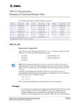
See Figure 1 for a diagram showing how the Model 375 Area Monitors are
connected to a single server.
1. Install Internet Information Services (IIS)
Windows XP – Page 27
Windows Vista – Page 29
Windows 7 – Page 32
Windows Server 2008 – Page 36
Windows Server 2003 – Page 42
Ludlum Measurements, Inc.
Page 9
April 2014
Model 375 Webpage and Supervisor Service
Software Manual
2. Install Microsoft .NET Framework 4.0 – Page 45
3. Install SQL Server – Page 46
This step is only necessary if SQL Server is not already installed on the
Supervisor computer and you plan to use the SQL Server 2008 Express
installation package provided by LMI.
4. Install Model 375 Web Page and Supervisor Service – Page 52
5. Configure SQL Server Manually (optional) – Page 59
This step is only necessary if SQL Server was not automatically
configured in the Model 375 Web Page And Service installation.
6. Configure Internet Information Services Manually (optional)
This step is only necessary if IIS was not automatically configured in the
Model 375 Web Page and Supervisor Service installation.
Windows XP – Page 66
Windows Vista – Page 70
Windows 7 – Page 73
Windows Server 2008 – Page 77
Windows Server 2003 – Page 81
7. Configure Model 375 Supervisor Service using the Service Utility – Page
94
8. Configure each Model 375 Area Monitor
If your area monitor has Ethernet firmware version N12 or later, refer
to Page 89. Otherwise, refer to Page 91.
9. Configure cameras (optional) – Page Error! Bookmark not defined.
Ludlum Measurements, Inc.
Page 10
April 2014
Model 375 Webpage and Supervisor Service
Software Manual
Figure 1 – Single Server Network Diagram
Installation Overview - Multiple Servers
The Model 375 Web Page and Supervisor Service can also be installed using
multiple servers, if desired. It is possible to install the webpage, Supervisor
service, and SQL Server database on separate servers.
The following is an overview of the steps necessary to get everything up and
running. For best results, bookmark the following page for easy reference.
Ludlum Measurements, Inc.
Page 11
April 2014
Model 375 Webpage and Supervisor Service
Software Manual
Some of the listed installation steps contain different sets of instructions for
different operating systems. Page numbers are included with each step to allow
for easier navigation of the manual.
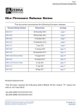
See Figure 2 for a diagram showing how the Model 375 Area Monitors are
connected to multiple servers.
1. Install the Model 375 Supervisor Service on the server that will host the
Supervisor service.
NOTE: If the Microsoft .NET 4.0 Framework is not installed refer to
page 45 to install the .NET 4.0 Framework before proceeding.
Refer to the “Install Model 375 Web Page and Service” section on Page
52. Make sure that the “Model 375 Supervisor Service”, “Model 375
Supervisor Server Utility”, and the “Model 375 Setup Utility” options
are the only installation options chosen before completing installation.
After installation is complete, leave the “Start Model 375 Supervisor
Service” option checked before clicking “Finish”.
Open the Service Utility and configure the Supervisor service, as desired.
Refer to page 94 for further details on the Service utility.
After the Supervisor service is configured, browse to the directory where
the Supervisor service is installed. There should be a file named
“settings.config”. Save this file to a removable media device; you will
need to copy this file to the server hosting the Model 375 Webpage.
2. Install the Model 375 Webpage on the server that will host the Model
375 Webpage.
NOTE: If the Microsoft .NET 4.0 Framework is not installed on the
server, refer to page 45 to install the .NET 4.0 Framework before
proceeding.
Refer to the “Install Model 375 Web Page and Supervisor Service”
section on Page 52. Make sure that the “Model 375 Webpage” option is
the only installation option chosen. If it is desired to configure Internet
Information Services automatically, the IIS Configuration option should
also be selected.
After installation is complete, copy the “settings.config” file from Step 1
to the directory where the Model 375 Webpage installation directory.
Ludlum Measurements, Inc.
Page 12
April 2014
Model 375 Webpage and Supervisor Service
Software Manual
3. Install Internet Information Services (IIS) on the server that will host
the Model 375 Webpage.
Refer to the appropriate page from the list below to install IIS.
Windows XP – Page 27
Windows Vista – Page 29
Windows 7 – Page 32
Windows Server 2008 – Page 36
Windows Server 2003 – Page 42
4. Configure Internet Information Services (IIS) on the server that will
host the Model 375 Webpage (optional).
If IIS was automatically configured during the Model 375 Web Page and
Supervisor Service installation, no further configuration is necessary.
If IIS was not automatically configured during the Model 375 Web Page
and Supervisor Service installation, refer to the appropriate page from
the list below to configure IIS.
Windows XP – Page 66
Windows Vista – Page 70
Windows 7 – Page 73
Windows Server 2008 – Page 77
Windows Server 2003 – Page 81
5. Install SQL Server on the server that will host the Model 375 Database
(optional)
If SQL Server is already installed on the server hosting the Model 375
database, proceed to the next step.
If SQL Server is not installed and you plan to install SQL Server 2008
Express from the LMI CD, refer to page 46.
6. Configure SQL Server on the server that will host the Model 375
Database (optional)
The Model 375 Web Page and Supervisor Service installation package
can be used to automatically configure SQL Server for use with the
Model 375 Supervisor Service. To do this, simply run the Model 375
Web Page and Supervisor Service setup and uncheck every option
except for the “Configure SQL Server 2005/2008” option.
If you need to configure SQL Server manually, refer to page 59.
Ludlum Measurements, Inc.
Page 13
April 2014
Model 375 Webpage and Supervisor Service
Software Manual
Figure 2 – Multiple Servers Network Diagram
Upgrading an Existing Web Page and Supervisor Service
Installation – Windows XP
1. Click on the Start Menu, then click on “Control Panel”.
2. Double-click on “Add/Remove Programs”.
3. Scroll through the list of currently installed programs and find “Model
375 Supervisor Service”.
NOTE: If “Model 375 Supervisor Service” does not exist, proceed to
Ludlum Measurements, Inc.
Page 14
April 2014
Model 375 Webpage and Supervisor Service
Software Manual
either the “Installation Overview – Single Server” section on page 9 or
the “Installation Overview – Multiple Servers” section on page 11,
whichever is appropriate.
4. Click on “Model 375 Supervisor Service” and click the “Remove”
button.
5. Click “Yes” in the confirmation prompt to proceed with un-installation
of the Model 375 Supervisor Service.
6. On the Ludlum Model 375 Web Page and Supervisor Service
installation CD, double-click the “setup_xp” setup file.
7. When un-installation is complete, proceed to the “Completing the Web
Page and Supervisor Service Upgrade” section on page 21.
Upgrading an Existing Web Page and Supervisor Service
Installation – Windows Vista
1. Click on the Start Menu, then click on “Control Panel”.
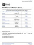
2. If the Control Panel resembles Figure 3, the Control Panel is set to
Category view. If the Control Panel is set to Category view, click on
“Programs”, then click on “Programs and Features”. If the Control
Panel is not set to Category view, click on “Programs and Features”
Figure 3 - Control Panel
Ludlum Measurements, Inc.
Page 15
April 2014
Model 375 Webpage and Supervisor Service
Software Manual
See Figure 4 for a screen shot of the Programs and Features window.
Figure 4 – Programs and Features window
3. Scroll through the list of currently installed programs and find “Model
375 Supervisor Service”.
NOTE: If “Model 375 Supervisor Service” does not exist, proceed to
either the “Installation Overview – Single Server” section on page 9 or
the “Installation Overview – Multiple Servers” section on page 11,
whichever is appropriate.
4. Click on “Model 375 Supervisor Service” and click the “Remove”
button.
5. Click “Yes” in the confirmation prompt to proceed with un-installation
of the Model 375 Supervisor Service.
6. On the Ludlum Model 375 Web Page and Supervisor Service
installation CD, double-click the “setup_vista” setup file.
7. When un-installation is complete, proceed to the “Completing the Web
Page and Supervisor Service Upgrade” section on page 21.
Ludlum Measurements, Inc.
Page 16
April 2014
Model 375 Webpage and Supervisor Service
Software Manual
Upgrading an Existing Web Page and Supervisor Service
Installation – Windows 7
1. Click on the Start Menu, then click on “Control Panel”.
2. If the Control Panel resembles Figure 5 the Control Panel is set to
Category view. If the Control Panel is set to Category view, click on
“Programs”, then click on “Programs and Features”.
If the Control Panel is not set to Category view, click on “Programs and
Features”.
3. See Figure 5 for a screen shot of the Programs and Features window.
Figure 5 – Control Panel in Category View
Ludlum Measurements, Inc.
Page 17
April 2014
Model 375 Webpage and Supervisor Service
Software Manual
Figure 6 – Programs and Features window
4. Scroll through the list of currently installed programs and find “Model
375 Supervisor Service”.
NOTE: If “Model 375 Supervisor Service” does not exist, proceed to
either the “Installation Overview – Single Server” section on page 9 or
the “Installation Overview – Multiple Servers” section on page 11,
whichever is appropriate.
5. Click on “Model 375 Supervisor Service” and click the “Remove”
button.
6. Click “Yes” in the confirmation prompt to proceed with un-installation
of the Model 375 Supervisor Service.
7. On the Ludlum Model 375 Web Page and Supervisor Service
installation CD, double-click the “setup_win7” setup file.
8. When un-installation is complete, proceed to the “Completing the Web
Page and Supervisor Service Upgrade” section on page 21.
Upgrading an Existing Web Page and Supervisor Service
Installation – Windows Server 2008
1. Click on the Start Menu, then click on “Control Panel”.
Ludlum Measurements, Inc.
Page 18
April 2014
Model 375 Webpage and Supervisor Service
Software Manual
2. If the Control Panel resembles Figure 7, the Control Panel is set to
Category view. If the Control Panel is set to Category view, click on
“Programs”, then click on “Programs and Features”.
If the Control Panel is not set to Category view, click on “Programs and
Features”.
3. See Figure 7 for a screen shot of the Programs and Features window.
Figure 7 – Control Panel in Category View
Ludlum Measurements, Inc.
Page 19
April 2014
Model 375 Webpage and Supervisor Service
Software Manual
Figure 8 – Program and Features window
4. Scroll through the list of currently installed programs and find “Model
375 Supervisor Service”.
NOTE: If “Model 375 Supervisor Service” does not exist, proceed to
either the “Installation Overview – Single Server” section on page 9or
the “Installation Overview – Multiple Servers” section on page 11,
whichever is appropriate.
5. Click on “Model 375 Supervisor Service” and click the “Remove”
button.
6. Click “Yes” in the confirmation prompt to proceed with un-installation
of the Model 375 Supervisor Service.
7. On the Ludlum Model 375 Web Page and Supervisor Service
installation CD, double-click the “setup_ws2008” setup file.
8. When un-installation is complete, proceed to the “Completing the Web
Page and Service Upgrade” section on page 21.
Ludlum Measurements, Inc.
Page 20
April 2014
Model 375 Webpage and Supervisor Service
Software Manual
Upgrading an Existing Web Page and Supervisor Service
Installation – Windows Server 2003
1. Click on the Start Menu, point the cursor at “Control Panel”, and click
on “Add or Remove Programs”.
2. Scroll through the list of currently installed programs and find “Model
375 Supervisor Service”.
NOTE: If “Model 375 Supervisor Service” does not exist, proceed to
either the “Installation Overview – Single Server” section on page 9 or
the “Installation Overview – Multiple Servers” section on page 11,
whichever is appropriate.
3. Click on “Model 375 Supervisor Service” and click the “Remove”
button.
4. Click “Yes” in the confirmation prompt to proceed with un-installation
of the Model 375 Supervisor Service.
5. On the Ludlum Model 375 Web Page and Supervisor Service
installation CD, double-click the “setup_ws2003” setup file.
6. When un-installation is complete, proceed to the “Completing the Web
Page and Service Upgrade” section below.
Completing the Web Page and Supervisor
Service Upgrade
The following instructions are for completing the upgrade to the new Model 375
Web Page and Supervisor Service Software version. These instructions assume
that the Model 375 Web Page and Supervisor Service is uninstalled.
Ludlum Measurements, Inc.
Page 21
April 2014
Model 375 Webpage and Supervisor Service
Software Manual
1. When the Welcome screen appears, click “Next”. See Figure 9.
Figure 9 – Model 375 Web Page and Supervisor Service installation welcome screen
2. If the installer is running with Administrative privileges, click “Next”.
See Figure 10.
Figure 10 – Model 375 Web Page and Supervisor Service installation warning screen
Ludlum Measurements, Inc.
Page 22
April 2014
Model 375 Webpage and Supervisor Service
Software Manual
3. Click “Next” to accept the license agreement. See Figure 11.
Figure 11 – Model 375 Web Page and Supervisor Service License Agreement screen
4. Click “Next” to accept the default component selections. See Figure 12.
Figure 12 – Model 375 Web Page and Supervisor Service Selection Screen 1
5. Click “Next” to accept the default database configuration selection. See
Figure 13.
Ludlum Measurements, Inc.
Page 23
April 2014
Model 375 Webpage and Supervisor Service
Software Manual
Figure 13 – Model 375 Web Page and Supervisor Service Selection screen 2
6. Uncheck the “Configure Internet Information Services (IIS)” option
and click “Next”. See Figure 14.
Figure 14 – Model 375 Web Page and Supervisor Service Configure IIS
7. Click “Next” to accept the default installation directory, or click
“Browse” to select a different installation directory. See Figure 15.
Ludlum Measurements, Inc.
Page 24
April 2014
Model 375 Webpage and Supervisor Service
Software Manual
Figure 15 – Model 375 Web Page and Supervisor Service Installation Location
8. Verify that the selected options are correct and click “Next” to begin
installation. See Figure 16.
Figure 16 – Model 375 Web Page and Supervisor Service Ready to Install
Ludlum Measurements, Inc.
Page 25
April 2014
Model 375 Webpage and Supervisor Service
Software Manual
9. When installation is complete, your screen should resemble Figure 17.
Figure 17 – Model 375 Web Page and Supervisor Service Installation Finished
10. Before starting the Supervisor service, open the SQL Server
Management Studio.
11. Open the file UpgradeAreaMonitorTable.sql which is located on the
installation CD on in the sql folder where the Supervisor service is
installed.
12. Execute the SQL script to update the table for the new version.
13. After the script runs, click finish on the installer.
14. If the Model 375 Supervisor Service was functioning correctly before
the upgrade, no further action is required.
Ludlum Measurements, Inc.
Page 26
April 2014
Model 375 Webpage and Supervisor Service
4
Section
Software Manual
IIS Installation
The steps to install IIS will be different depending on the operating system.
Refer to applicable operating system documentation for the correct procedure to
install IIS. A Windows Operating System CD may be required to complete
installation.
IIS Server Installation – Windows XP
These instructions are for installing Internet Information Services under
Windows XP Professional. The Windows Install CD may be required.
1. Navigate to the Control Panel and double-click on Add/Remove
Programs
2. Click on Add/Remove Windows Components. See Figure 18.
Figure 18 – Windows Components Wizard
Ludlum Measurements, Inc.
Page 27
April 2014
Model 375 Webpage and Supervisor Service
Software Manual
3. Check “Internet Information Services (IIS)” and click the “Details…”
button. See Figure 19.
Figure 19 – Windows Components Wizard
4. Uncheck SMTP Service, and click “OK”. See Figure 20.
Figure 20 – Internet Information Services (IIS)
5. Click “Next” to install IIS.
6. When installation is complete, click “Finish” and proceed to the “.NET
Framework 4.0 Installation” section on page 45.
Ludlum Measurements, Inc.
Page 28
April 2014
Model 375 Webpage and Supervisor Service
Software Manual
IIS Server Installation – Windows Vista
These instructions are for installing Internet Information Services under
Windows Vista. The Windows CD may be required.
1. Click on the Start Menu, then click on “Control Panel”.
2. If the Control Panel resembles Figure 21, the Control Panel is set to
Category view. If the Control Panel is set to Category view, click on
“Programs”, then click on “Programs and Features”.
If the Control Panel is not set to Category view, click on “Programs and
Features”.
3. See Figure 22 for a screen shot of the Programs and Features window.
Figure 21 – Control Panel
Ludlum Measurements, Inc.
Page 29
April 2014
Model 375 Webpage and Supervisor Service
Software Manual
Figure 22 – Program and Features
4. Click on “Turn Windows features on or off”.
5. Click on the plus icon next to “Internet Information Services”.
6. Click on the plus icon next to “Web Management Tools”.
7. Click on the plus icon next to “IIS 6 Management Compatibility” and
check the “IIS 6 Scripting Tools” option. Dependent options will be
checked automatically.
8. Check the “IIS Management Console” and the “IIS Management
Scripts and Tools” options.
9. Click on the plus icon next to “World Wide Web Services”.
10. Click on the plus icon next to “Application Development Features”.
11. Check the “ASP.NET” option. Dependent options will be checked
automatically.
12. Click on the plus icon next to “Common HTTP Features” and check
the “Static Content” option.
Ludlum Measurements, Inc.
Page 30
April 2014
Model 375 Webpage and Supervisor Service
Software Manual
13. Verify that the selected Internet Information Services (IIS) options look
like Figure 23 and Figure 24 on the following pages and click “OK” to
install Internet Information Services.
NOTE: You may be prompted for the Windows Installation CD.
14. Close the Programs and Features window.
Figure 23 – Windows Features
Ludlum Measurements, Inc.
Page 31
April 2014
Model 375 Webpage and Supervisor Service
Software Manual
Figure 24 – Windows Features
15. Proceed to the “.NET Framework 4.0 Installation” section on page 45.
IIS Server Installation – Windows 7
These instructions are for installing Internet Information Services under
Windows 7. The Windows CD may be required.
1. Click on the Start Menu, then click on “Control Panel”.
2. If the Control Panel resembles Figure 29, the Control Panel is set to
Category view. If the Control Panel is set to Category view, click on
“Programs”, then click on “Programs and Features”.
If the Control Panel is not set to Category view, click on “Programs and
Features”.
3. See Figure 30 for a screen shot of the Programs and Features window.
Ludlum Measurements, Inc.
Page 32
April 2014
Model 375 Webpage and Supervisor Service
Software Manual
Figure 25 – Control Panel
Figure 26 – Programs and Features
4. Click on “Turn Windows features on or off” in the left pane of the
Programs and Features window.
Ludlum Measurements, Inc.
Page 33
April 2014
Model 375 Webpage and Supervisor Service
Software Manual
5. Click on the plus icon next to “Internet Information Services”.
6. Click on the plus icon next to “Web Management Tools”.
7. Click on the plus icon next to “IIS 6 Management Compatibility” and
check the “IIS 6 Scripting Tools” option. Dependent options will be
checked automatically.
8. Check the “IIS Management Console” and the “IIS Management
Scripts and Tools” options.
9. Click on the plus icon next to “World Wide Web Services”.
10. Click on the plus icon next to “Application Development Features”.
11. Check the “ASP.NET” option. Dependent options will be checked
automatically.
12. Click on the plus icon next to “Common HTTP Features” and check
the “Static Content” option.
13. Verify that your selected Internet Information Services (IIS) options
resemble Figure 31 and Figure 32 on the following pages and click
“OK” to install Internet Information Services.
NOTE: You may be prompted for the Windows Installation CD.
14. Close the “Programs and Features” window.
Ludlum Measurements, Inc.
Page 34
April 2014
Model 375 Webpage and Supervisor Service
Software Manual
Figure 27 – Windows Features
Figure 28 – Windows Features
Ludlum Measurements, Inc.
Page 35
April 2014
Model 375 Webpage and Supervisor Service
Software Manual
15. Proceed to the “.NET Framework 4.0 Installation” section on page 45.
IIS Server Installation – Windows Server 2008
These instructions are for installing Internet Information Services under
Windows Server 2008. The Windows CD may be required.
Also included are instructions on how to install the Windows Power Shell
feature, which is required by SQL Server.
1. Click on the Start Menu and click on “Server Manager” to open the
Server Manager window. See Figure 39.
Figure 29 – Server Manager
2. Under the “Roles Summary” group box in the middle pane of the
Server Manager window, click on “Add Roles”.
3. In the “Select Server Roles” window, check “Web Server (IIS)” and
click “Next.” See Figure 40.
Ludlum Measurements, Inc.
Page 36
April 2014
Model 375 Webpage and Supervisor Service
Software Manual
Figure 30 – Add Rules Wizard (Select Server Roles)
4. Under the “Application Deployment” node, check the “ASP.NET”
option. When the “Add Roles Wizard” pop-up appears, click “Add
Required Role Services”. See Figure 41.
Figure 31 – Add Rules Wizard (Add role services required for ASP.NET)
5. Scroll down and check the “IIS Management Scripts and Tools” option.
6. Check the “IIS 6 Scripting Tools” option. When the “Add Roles
Wizard” pop-up appears, click “Add Required Role Services”.
7. Check the “IIS 6 Management Console” option.
Ludlum Measurements, Inc.
Page 37
April 2014
Model 375 Webpage and Supervisor Service
Software Manual
8. Verify that the selected role services resemble Figure 42 below and
Figure 43, then click “Next”.
Figure 32 – Add Roles Wizard (Select Role Services 1)
Figure 33 – Add Roles Wizard (Select Role Services 2)
Ludlum Measurements, Inc.
Page 38
April 2014
Model 375 Webpage and Supervisor Service
Software Manual
9. Click “Install”. See Figure 44.
Figure 34 – Add Roles Wizard (Confirm Installation Selections)
10. If Internet Information Services (IIS) is installed successfully, click
“Close”. See Figure 45.
Ludlum Measurements, Inc.
Page 39
April 2014
Model 375 Webpage and Supervisor Service
Software Manual
Figure 35 – Add Roles Wizard (Installation Results)
11. In the Server Manager window, under the “Features Summary” group
box, click on “Add Features”.
12. In the “Add Features Wizard”, check “Windows Power Shell”. See
Figure 46.
NOTE: If the Windows Power Shell checkbox is already checked,
Windows Power Shell is already installed. Proceed to the “.NET
Framework 4.0 Installation” section on page 45.
Ludlum Measurements, Inc.
Page 40
April 2014
Model 375 Webpage and Supervisor Service
Software Manual
Figure 36 – Add Features Wizard (Select Features)
13. Click “Install” to install Windows Power Shell. See Figure 47.
Figure 37 – Add Features Wizard (Confirm Installation Selections)
Ludlum Measurements, Inc.
Page 41
April 2014
Model 375 Webpage and Supervisor Service
Software Manual
14. When installation is complete, click “Close”. See Figure 48.
Figure 38 – Add Features Wizard (Installation Results)
15. Proceed to the “.NET Framework 4.0 Installation” section on page 45.
IIS Server Installation – Windows Server 2003
These instructions are for installing Internet Information Services under
Windows Server 2003. The Windows CD may be required.
1. Go to the Start menu, click on “Control Panel”, and click on
“Add/Remove Programs”.
2. In the “Add/Remove Programs” window, click on the “Add/Remove
Windows Components” button. See Figure 51.
Ludlum Measurements, Inc.
Page 42
April 2014
Model 375 Webpage and Supervisor Service
Software Manual
Figure 39 – Windows Components Wizard
3. Click on “Application Server”, then click on the “Details” button. See
Figure 52.
Figure 40 – Application Server
4. Check the box next to “ASP.NET”.
5. Click on “Internet Information Services”, then click on the “Details”
button. See Figure 53.
Ludlum Measurements, Inc.
Page 43
April 2014
Model 375 Webpage and Supervisor Service
Software Manual
Figure 41 – Internet Information Services (IIS)
6. Click the “OK” button in the “Application Server” window from Figure
52.
7. Click “Next” in the “Windows Components Wizard” window from
Figure 51 to install IIS.
NOTE: The Windows installation CD may be required.
8. If the Internet Information Services is successful, click “Finish” and
proceed to the “.NET 4.0 Framework Installation” section.
Ludlum Measurements, Inc.
Page 44
April 2014
Model 375 Webpage and Supervisor Service
5
Section
Software Manual
.Net 4.0 Installation
1. If you are running Windows XP or Windows Server 2003, navigate
to the Control Panel and double-click on “Add/Remove
Programs”.
If you are running any other version of Windows, navigate to the
Control Panel and double-click on “Programs and Features”.
2. Check through the list of installed programs for “Microsoft .NET
Framework 4.0”. If you do not find it listed, proceed to Step 3.
If SQL Server is not installed and you plan to install the SQL Server
Express software provided by LMI, proceed to the “SQL Server
2008 Express Installation” section.
If SQL Server is already installed or you plan to install the full
version of SQL Server, proceed to the “Model 375 Web Page and
Service Installation” section on page 52.
3. If “Microsoft .NET Framework 4.0” is not listed, navigate to the
“Microsoft .NET Framework 4.0” folder on the Ludlum installation
CD and double-click on the file “dotNetFx40_Full_x86_x64.exe”.
If a window shows up that has options for repairing or uninstalling
the .NET framework, then click on the CANCEL option: the
computer already has the correct .NET software installed.
4. Click on NEXT and FINISH as appropriate to install the .NET
package.
5. If SQL Server is not installed and you plan to install the SQL Server
Express software provided by LMI, proceed to the “SQL Server
2008 Express Installation” section.
If SQL Server is already installed or you plan to install the full
version of SQL Server, proceed to the “Model 375 Web Page and
Service Installation” section on page 46.
Ludlum Measurements, Inc.
Page 45
April 2014
Model 375 Webpage and Supervisor Service
6
Section
Software Manual
SQL Server Installation
SQL Server 2008 Express R2 editions (x86 and x64) are included on the
installation DVD and can be installed by following the steps below.
Windows PowerShell 2.0 is a prerequisite before installing SQL Server 2008 R2
Express. Install PowerShell through Windows Update before attempting to
install SQL Server 2008 R2 Express.
1. Navigate to the SQL Server Express 2008 folder on the DVD and
double-click SQLEXPRADV_x86_ENU.EXE to install the 32-bit
version or double-click SQLEXPADV_x64_ENU.EXE to install the
64-bit version.
2. If the following window (Figure 54) appears, download and install
Microsoft Windows Installer 4.5 . Restart the computer if necessary. If
the window does not appear, skip to step 3.
Figure 42 - Microsoft Windows Installer 4.5 Requirement
3. From the SQL Server Installation Center click New installation or add
features to an existing installation. See Figure 55.
Ludlum Measurements, Inc.
Page 46
April 2014
Model 375 Webpage and Supervisor Service
Software Manual
Figure 43 – SQL Server Installation Center
4. Click New installation or add features to an existing installation.
5. Accept the License terms and click Next to continue.
Figure 44 – License Terms
Ludlum Measurements, Inc.
Page 47
April 2014
Model 375 Webpage and Supervisor Service
Software Manual
6. From the Feature Selection screen, accept the defaults and click Next.
See Figure 57.
Figure 45 – Feature Selection
7. If there are no other instances of SQL Server, accept the defaults and
click Next. If there are one or more installed instances, check the name
of this instance to an appropriate value. When finished configuring the
instance, click Next. See Figure 58.
Figure 46 – Instance Configuration
Ludlum Measurements, Inc.
Page 48
April 2014
Model 375 Webpage and Supervisor Service
Software Manual
8. Consult your Network Administrator for the correct user accounts to
use. If you are unsure, use the NT AUTHORITY/NETWORK
SERVICE account. See Figure 59. Click Next after configuring the
accounts.
Figure 47 – Service Accounts
9. Change the Authentication Mode to Mixed Mode (SQL Server
Authentication and Windows Authentication). Enter a password for
the "sa" user. Click Next. See Figure 60.
Figure 48 – Account Provisioning
Ludlum Measurements, Inc.
Page 49
April 2014
Model 375 Webpage and Supervisor Service
Software Manual
10. Select Install the native mode default configuration from the
Reporting Services Configuration screen and click Next. See Figure
44.
Figure 49 – Reporting Services Configuration
11. Click Next on the Error Reporting screen. See Figure 62.
Figure 50 – Error Reporting
Ludlum Measurements, Inc.
Page 50
April 2014
Model 375 Webpage and Supervisor Service
Software Manual
12. After the installation is complete, click the Close button and then close
the SQL Server Installation Center. See Figure 63.
Figure 51 – SQL Server 2008 Completed Installation
Ludlum Measurements, Inc.
Page 51
April 2014
Model 375 Webpage and Supervisor Service
7
Section
Software Manual
Web Page and Supervisor
Service Installation
Beginning with version 1.5.2, the Web Page and Supervisor Service installer can
automatically configure Internet Information Services (IIS), as well as SQL
Server 2008 Express and SQL Server 2008 Express. The new automatic
configuration options were created to greatly simplify installation of the Model
375 Web Page and Supervisor Service.
The Model 375 Web Page and Service installation CD contains custom installer
files for the following operating systems:
Windows XP
Windows Server 2003
Windows Server 2008
Windows Vista
Windows 7
The Model 375 Web Page and Supervisor Service installer MUST be running in
either the Windows Administrator user account or a Windows user account with
Administrator privileges; else, the installer may not function correctly
Each installer option will be described in detail on the following pages.
1. On the Ludlum Model 375 Web Page and Supervisor Service
installation CD, double-click the appropriate setup file. The name of
the setup file used MUST match the Supervisor computer’s Windows
operating system.
2. When the Welcome screen appears, click “Next”. See Figure 64.
Ludlum Measurements, Inc.
Page 52
April 2014
Model 375 Webpage and Supervisor Service
Software Manual
Figure 52 – Model 375 Web Page and Supervisor Service Installation (Welcome)
3. The warning screen simply warns the user to make sure that the installer
is running with Administrative privileges. If the installer is running with
Administrative privileges, click “Next”. See Figure 65.
Figure 53 – Model 375 Web Page and Supervisor Service Installation (Warning)
4. Click “Next” to accept the license agreement. See Figure 66.
Ludlum Measurements, Inc.
Page 53
April 2014
Model 375 Webpage and Supervisor Service
Software Manual
Figure 54 – Model 375 Web Page and Supervisor Service Installation (License Agreement)
5. The next screen asks the user to select the components that will be
installed on the Supervisor computer. The following is a list of
components to install, as well as a short description for each
component:
Supervisor Service – The Windows service that runs in the
background on the Supervisor computer. The Supervisor service is
responsible for collecting Model 375 data and storing that data in a
database on the Supervisor computer.
Service Utility – The software used to configure the Supervisor service.
The Service Utility is discussed in further detail, starting on Page 94.
ASP Web Application – The software used to run the Model 375 web
page. The Model 375 web page is discussed in further detail, starting on
Page 102.
Device Finder – The software used to search for any Model 375
instruments connected to the local network subnet.
Area Monitor Utility – The software used to detect and configure any
Model 375 instruments that are connected to the local network subnet.
The Area Monitor Utility is discussed in further detail, starting on Page
91.
By default, all five options are selected. Uncheck any components that
are not desired and click “Next”. See Figure 67.
Ludlum Measurements, Inc.
Page 54
April 2014
Model 375 Webpage and Supervisor Service
Software Manual
Figure 55 – Model 375 Web Page and Supervisor Service Installation (Select Components to Install)
6. The database configuration option screen allows the user to select which
version of SQL Server Express to configure.
If you installed SQL Server 2008 Express using the instructions from
the “SQL Server 2008 Express Installation” section, select the
“Configure SQL Server 2008” option.
If SQL Server was already installed prior to reading this manual, select
the “Don’t Configure SQL Server” option.
Select the appropriate database configuration option and click “Next”.
See Figure 68.
Ludlum Measurements, Inc.
Page 55
April 2014
Model 375 Webpage and Supervisor Service
Software Manual
Figure 56 – Model 375 Web Page and Supervisor Service Installation (Database Configuration Option)
7. The Internet Information Services (IIS) configuration screen allows the
user to select whether or not the installer automatically configures IIS in
order to allow the Model 375 Webpage to work properly.
By default, IIS is configured automatically by the installer. If it is desired
to configure IIS manually, uncheck the IIS Configuration option and
click “Next”. See Figure 69.
Manual IIS configuration instructions can be found in the “Configuring
IIS Manually” section.
Figure 57 – Model 375 Web Page and Supervisor Service Installation (IIS Configuration Option)
Ludlum Measurements, Inc.
Page 56
April 2014
Model 375 Webpage and Supervisor Service
Software Manual
8. The “Select Destination Location” screen allows the user to select the
directory where the Model 375 Supervisor Service will be installed. The
default directory is C:\Program Files\Ludlum Measurements,
Inc\Model 375 Supervisor Service.
If this is not the desired installation directory, use the Browse button to
select a different directory. Once the destination directory is selected,
click “Next”. See Figure 70.
Figure 58 – Model 375 Web Page and Supervisor Service Installation (Destination Location)
9. Confirm that the selected setup information is correct and click
“Install”. See Figure 71.
Ludlum Measurements, Inc.
Page 57
April 2014
Model 375 Webpage and Supervisor Service
Software Manual
Figure 59 – Model 375 Web Page and Supervisor Service Installation (Ready to Install)
10. Once installation is complete, uncheck the “Start Supervisor Service”
option if you do not wish to start the Supervisor service. Click “Finish”.
See Figure 72.
Figure 60 – Model 375 Web Page and Supervisor Service Installation (Finished Installation)
11. For the Save to CSV feature to work, the security permissions for the
installation folder need to have the following user added with write
permissions:
Windows 7/Server 2008: IIS_IUSRS
Windows XP/Server 2003: ASPNET
Ludlum Measurements, Inc.
Page 58
April 2014
Model 375 Webpage and Supervisor Service
Software Manual
12. If the installer was used to automatically configure both SQL Server
Express and Internet Information Services (IIS), proceed to the
“Testing the Web Server” section on page 87.
If configuration for SQL Server is to be done manually, proceed below
for manual configuration instructions.
If configuration for IIS is to be done manually, proceed to the
appropriate section from the following list:
Configuring IIS in Windows XP – page 66
Configuring IIS in Windows Vista – page 70
Configuring IIS in Windows 7 – page 73
Configuring IIS in Windows Server 2008 – page 77
Configuring IIS in Windows Server 2003 – page 81
Configuring SQL Server Manually (optional)
If you selected the “Configure SQL Server 2008 Express” option in the Model
375 Web Page and Supervisor Service installer, skip this section.
If you are configuring SQL Server manually, go through the following steps.
1. Open SQL Server Management Studio. To do this, click on the “Start”
menu, point the cursor to “All Programs”, point the cursor to
“Microsoft SQL Server 2008”, and click on “SQL Server Management
Studio”.
NOTE: If the Express version of SQL Server 2008 is installed, the
program will be named “SQL Server Management Studio Express”.
2. Click on the “Authentication” combo box and change the
Authentication Mode to “SQL Server Authentication”.
3. Enter “sa” (lower-case, without the quotation marks) into the “Login”
combo box.
4. Enter the password for the System Administrator (“sa”) account into
the “Password” combo box. See Figure 73.
NOTE: If you installed SQL Server 2008 Express from the Ludlum
installation CD, make sure to enter the password that was set in Step 7
of the “SQL Server 2008 Express Installation” section.
If you did not install SQL Server 2008 Express and you do not know
the “sa” account password, contact your database administrator.
Ludlum Measurements, Inc.
Page 59
April 2014
Model 375 Webpage and Supervisor Service
Software Manual
Figure 61 – SQL Server Management Studio Login Window
5. Click “OK”. The SQL Server Management Studio window should
resemble Figure 74.
Ludlum Measurements, Inc.
Page 60
April 2014
Model 375 Webpage and Supervisor Service
Software Manual
Figure 62 – SQL Server Management Studio
6. Right-click on “Databases” in the left panel and click on “New
Database”.
7. Type “lmi_area_monitor” (lower-case, without the quotation marks)
into the “Database name” text box. See Figure 75.
Ludlum Measurements, Inc.
Page 61
April 2014
Model 375 Webpage and Supervisor Service
Software Manual
Figure 63 – Create New Database
8. Click “OK”.
9. In the SQL Server Management Studio window, click on the plus icon
next to the “Databases” folder in the left pane. The SQL Server
Management Studio window should now resemble Figure 76.
Ludlum Measurements, Inc.
Page 62
April 2014
Model 375 Webpage and Supervisor Service
Software Manual
Figure 64 – SQL Server Management Studio Express showing new database
10. Right-click on the “Security” folder in the left pane. Point the cursor to
“New”, then click on “Login”.
11. Enter “ludlum” (lower-case, without the quotation marks) into the
“Login name” text box.
12. Click on the radio button next to “SQL Server authentication”.
13. Uncheck the “Enforce Password Policy” option.
14. Enter “areamonitor” (lower-case, without the quotation marks) into
both the “Password” and “Confirm Password” text boxes.
NOTE: The login name and password in the above steps are the
default values that the Supervisor service uses to log into the database.
These values may be changed, if desired; however, the login name and
password MUST match the user name and password stored in the
Supervisor Server Utility; else, the Supervisor service will not function
properly. The Supervisor Server Utility is discussed in detail, starting on
page 91.
Ludlum Measurements, Inc.
Page 63
April 2014
Model 375 Webpage and Supervisor Service
Software Manual
15. Click on the “Default database” combo box and change the default
database to “lmi_area_monitor”.
16. Verify that the New Login window resembles Figure 77 before
continuing.
17. Click on “User Mapping” in the left pane of the New Login window.
18. Check “lmi_area_monitor” in the “Users mapped to this login” pane.
19. Check “db_owner” in the “Database role membership” pane. Leave
the “public” database role membership checked.
20. Verify that the New Login window resembles Figure 78, then click
“OK”.
21. In the SQL Server Management Studio window, click on the plus sign
next to the “Security”, then click on the plus sign next to the “Logins”
window. Your screen should now resemble Figure 79.
22. Close the SQL Server Management Studio window.
Figure 65 – New Login
Ludlum Measurements, Inc.
Page 64
April 2014
Model 375 Webpage and Supervisor Service
Software Manual
Figure 66 – User Mapping
Figure 67 – SQL Server Management Studio showing new login
Ludlum Measurements, Inc.
Page 65
April 2014
Model 375 Webpage and Supervisor Service
Software Manual
Configuring Internet Information Services Manually
(optional)
If you selected the “Configure Internet Information Services” option in the
Model 375 Web Page and Supervisor Service installer, skip this section.
If you are configuring Internet Information Services manually, proceed to the
appropriate instructions for your computer’s operating system.
Configuring IIS in Windows XP
1. Click on the Start Menu, then click on “Control Panel”.
2. If your Control Panel is configured for Classic View, double-click on
“Administrative Tools”. If your Control Panel is configured for
Category View, click on “Performance and Maintenance”, then click on
“Administrative Tools”.
3. Double-click on “Internet Information Services”.
NOTE: If the Internet Information Services shortcut does not exist,
refer to the “IIS Server Installation – Windows XP” section on page 27
to install Internet Information Services.
4. Click on the plus symbol next to your computer name, then click on the
plus symbol next to the “Web Sites” folder. See Figure 80.
Figure 68 – Internet Information Services
Ludlum Measurements, Inc.
Page 66
April 2014
Model 375 Webpage and Supervisor Service
Software Manual
5. Right-click on “Default Web Site”, point your cursor at “New”, and
click “Virtual Directory”. The Virtual Directory Creation Wizard will
appear. See Figure 81.
Figure 69 – Virtual Directory Creating Wizard
6. Click “Next” to continue.
7. Enter “AreaMonitor” (without the quotation marks) into the “Alias”
text box and click “Next”. See Figure 82.
NOTE: The alias for the virtual directory determines the URL used to
access the web interface. The URL will be
http://computername/virtual directory name.
Ludlum Measurements, Inc.
Page 67
April 2014
Model 375 Webpage and Supervisor Service
Software Manual
Figure 70 – Virtual Directory Creation Wizard (Virtual Directory Alias)
8. Click the “Browse” button and browse to the directory where the
Model 375 Supervisor Service is installed. By default, the installation
directory is “C:\Program Files\Ludlum Measurements, Inc\Model 375
Supervisor Service”.
9. Click “Next”. See Figure 83.
Figure 71 – Virtual Directory Creation Wizard (Web Site Content Directory)
10. Click “Next” to accept the default access permissions. See Figure 84.
Ludlum Measurements, Inc.
Page 68
April 2014
Model 375 Webpage and Supervisor Service
Software Manual
Figure 72 – Virtual Directory Creation Wizard (Access Permissions)
11. Click “Finish”. See Figure 85.
Figure 73 – Virtual Directory Creation Wizard (Completed)
12. In the Internet Information Services window, click on the plus sign next
to “Default Web Site”.
13. Right-click on the new “AreaMonitor” virtual directory, then click
“Properties”.
14. Click on the “Documents” tab, then click the “Add” button.
Ludlum Measurements, Inc.
Page 69
April 2014
Model 375 Webpage and Supervisor Service
Software Manual
15. Enter “CurrentStatus.aspx” (without the quotation marks) and click
“OK”.
16. In the Properties window, click on “CurrentStatus.aspx”, then click the
Up Arrow button until CurrentStatus.aspx is at the top of the default
documents list.
17. Verify that the Properties window resembles Figure 86, then click
“Apply” to accept the changes.
Figure 74 – AreaMonitor Properties (Documents)
18. Click on the “ASP.NET” tab and make sure that the ASP.NET version
is 4.0.30319. If it is not, click on the “ASP.NET” combo box and select
the “4.0.30319.” option.
19. Close the Internet Information Services window.
Configuring IIS in Windows Vista
1. Click on the Start Menu, then click on “Control Panel”.
2. In the Control Panel, click on “Classic View”.
3. Double-click on “Administrative Tools”, then double-click on “Internet
Information Services (IIS) Manager”.
Ludlum Measurements, Inc.
Page 70
April 2014
Model 375 Webpage and Supervisor Service
Software Manual
NOTE: If Internet Information Services (IIS) Manager does not exist
in Administrative Tools, refer to the “IIS Server Installation – Windows
Vista” section on page 29 to install Internet Information Services.
4. In the left pane of the IIS Manager window, click on the right arrow
next to your computer name, then click on the right arrow next to the
“Web Sites” folder. Your screen should resemble Figure 87.
Figure 75 – Internet Information Services (IIS) Manager
5. Right-click on “Default Web Site” and click “Add Application”.
6. In the “Alias” text box, enter in “AreaMonitor” (without the quotation
marks).
7. Click the “Select” button to the right of the “Application pool” text box.
8. Click on the “Application pool” drop-down box and select “ASP.NET
v4.0 Classic”, then click “OK”.
9. Click on the button next to the “Physical path” text box and browse to
the directory where the Model 375 Supervisor Service is installed. By
default, the installation directory is “C:\Program Files\Ludlum
Measurements, Inc\Model 375 Supervisor Service”.
10. Click “OK”. See Figure 88.
Ludlum Measurements, Inc.
Page 71
April 2014
Model 375 Webpage and Supervisor Service
Software Manual
Figure 76 – Add Application
11. In the left pane of the IIS Manager window, click the right arrow next to
“Default Web Site”. You should see the AreaMonitor application under
the default web site. See Figure 89.
Figure 77 – Internet Information Services (IIS) Manager showing AreaMonitor application
12. Click on “AreaMonitor” in the left pane of the IIS Manager window,
then double-click on “Default Document” in the middle pane.
Ludlum Measurements, Inc.
Page 72
April 2014
Model 375 Webpage and Supervisor Service
Software Manual
13. Click on the “File name(s)” text box. Make sure the cursor is positioned
at the beginning of the default document text.
14. Once the cursor is positioned, enter in “CurrentStatus.aspx” (without
the quotation marks), followed by a comma.
15. In the right pane of the IIS Manager window, click “Apply” to accept
the change. Your screen should resemble Figure 90.
16. Close the IIS Manager window.
Figure 78 – Default Document for AreaMonitor application
Configuring IIS in Windows 7
1. Click on the Start Menu, then click on “Control Panel”.
2. If the Control Panel resembles Figure 91, the Control Panel is set to
Category view. If the Control Panel is set to Category view, click on
“System and Security”, then click on “Administrative Tools”.
If the Control Panel is not set to Category view, click on
“Administrative Tools”.
See Figure 92 for a screen shot of the Administrative Tools window.
Ludlum Measurements, Inc.
Page 73
April 2014
Model 375 Webpage and Supervisor Service
Software Manual
Figure 79 – Control Panel
Figure 80 – Administrative Tools
3. Double-click on “Internet Information Services (IIS) Manager” to open
the IIS Manager window.
Ludlum Measurements, Inc.
Page 74
April 2014
Model 375 Webpage and Supervisor Service
Software Manual
NOTE: If Internet Information Services (IIS) Manager does not exist
in Administrative Tools, refer to the “IIS Server Installation – Windows
7” section on page 32 to install Internet Information Services.
4. Click on the right arrow next to “Sites” in the left pane of the IIS
Manager window.
5. Click on the right arrow next to “Default Web Site” in the left pane of
the IIS Manager window. See Figure 93.
Figure 81 – Internet Information Services (IIS) Manager
6. Right-click on “Default Web Site” and click on “Add Application”.
7. In the “Alias” text box, enter in “AreaMonitor” (without the quotation
marks).
8. Click the “Select” button to the right of the “Application pool” text box.
9. Click on the “Application pool” drop-down box and select “ASP.NET
v4.0 Classic”, then click “OK”.
10. Click on the button next to the “Physical path” text box and browse to
the directory where the Model 375 Supervisor Service is installed. By
default, the installation directory is “C:\Program Files\Ludlum
Measurements, Inc\Model 375 Supervisor Service”.
11. Click “OK”. See Figure 94.
Ludlum Measurements, Inc.
Page 75
April 2014
Model 375 Webpage and Supervisor Service
Software Manual
Figure 82 – Add Application
12. Click the right arrow next to “Default Web Site” in the left pane of the
IIS Manager window. You should now see the AreaMonitor application
under the default web site. See Figure 95.
Figure 83 – Internet Information Services (IIS) Manager showing AreaMonitor application
13. Click on “AreaMonitor” in the left pane of the IIS Manager window,
then double-click on “Default Document” in the middle pane.
Ludlum Measurements, Inc.
Page 76
April 2014
Model 375 Webpage and Supervisor Service
Software Manual
14. Click on “Add” in the right pane of the IIS Manager window to add a
new default document.
15. Enter in “CurrentStatus.aspx” (without the quotation marks) and click
“OK”. See Figure 96.
Figure 84 – Add Default Document
16. Verify that the IIS Manager window resembles Figure 97, then close the
IIS Manager window.
Figure 85 – Default Document for AreaMonitor application
Configuring IIS in Windows Server 2008
1. Click on the Start Menu, point the cursor at “Administrative Tools”,
and click on “Internet Information Services (IIS) Manager”.
Ludlum Measurements, Inc.
Page 77
April 2014
Model 375 Webpage and Supervisor Service
Software Manual
NOTE : If Internet Information Services (IIS) Manager does not exist
in Administrative Tools, refer to the “IIS Server Installation – Windows
Server 2008” section on page 36 to install Internet Information Services.
NOTE : It may be necessary to the ISAPI + CGI restrictions to allow
the ASP.NET v4.0.30319 Framework.
2. In the IIS Manager window, click on the plus symbol next to the “Sites”
folder, then click on the plus symbol next to “Default Web Site”. The
IIS Manager window should now resemble Figure 98.
Figure 86 – Internet Information Services (IIS) Manager
Right-click on “Default Web Site” and click on “Add Application”.
3. Enter “AreaMonitor” (without the quotation marks) into the “Alias”
text box.
4. Click the “Select” button to the right of the “Application pool” text box.
5. Click the “Application pool” drop-down box, select “ASP.NET v4.0
Classic Application Pool”, and click “OK”.
6. Click on the button next to the “Physical path” text box and browse to
the directory where the Model 375 Supervisor Service is installed. By
Ludlum Measurements, Inc.
Page 78
April 2014
Model 375 Webpage and Supervisor Service
Software Manual
default, the installation directory is “C:\Program Files\Ludlum
Measurements, Inc\Model 375 Supervisor Service”.
7. Click “OK”. See Figure 99.
Figure 87 – Add Application
8. Click the right arrow next to “Default Web Site” in the left pane of the
IIS Manager window. You should now see the AreaMonitor application
under the default web site. See Figure 100.
Ludlum Measurements, Inc.
Page 79
April 2014
Model 375 Webpage and Supervisor Service
Software Manual
Figure 88 – Internet Information Services (IIS) Manager showing AreaMonitor application
9. Click on “AreaMonitor” in the left pane of the IIS Manager window.
10. Double-click on “Default Document” in the middle pane of the IIS
Manager window.
11. Click on “Add” in the right pane of the IIS Manager window to add a
new default document to the AreaMonitor application.
12. In the “Add Default Document” dialog, enter in “CurrentStatus.aspx”
(without the quotation marks) in the “Name” text box, then click
“OK”. See Figure 101.
Figure 89 – Add Default Document
Ludlum Measurements, Inc.
Page 80
April 2014
Model 375 Webpage and Supervisor Service
Software Manual
13. Verify that the IIS Manager window resembles Figure 102, then close
the IIS Manager window.
Figure 90 – Default Document for AreaMonitor application
Configuring IIS in Windows Server 2003
1. Click on the Start Menu, point the cursor at “Administrative Tools”,
and click on “Internet Information Services (IIS) Manager”.
NOTE: If Internet Information Services (IIS) Manager does not exist
in Administrative Tools, refer to the “IIS Server Installation – Windows
Server 2003” section on page 42 to install Internet Information Services.
2. In the IIS Manager window, click on the plus symbol next to the
computer name, then click on the plus symbol next to the “Web Sites”
folder. The IIS Manager window should now resemble Figure 103.
Ludlum Measurements, Inc.
Page 81
April 2014
Model 375 Webpage and Supervisor Service
Software Manual
Figure 91 – Internet Information Services (IIS) Manager
3. Right-click on “AreaMonitor” in the left pane of the IIS Manager
window.
4. Right-click on “Default Web Site”, point your cursor at “New”, and
click “Virtual Directory”. The Virtual Directory Creation Wizard will
appear. See Figure 104.
Figure 92 – Virtual Directory Creation Wizard
5. Click “Next” to continue.
Ludlum Measurements, Inc.
Page 82
April 2014
Model 375 Webpage and Supervisor Service
Software Manual
6. Enter “AreaMonitor” (without the quotation marks) into the “Alias”
textbox. See Figure 105.
NOTE: The alias for the virtual directory determines the URL used to
access the web interface. The URL will be
http://computername/virtual directory name.
Figure 93 – Virtual Directory Alias
7. Click the “Browse” button and browse to the directory where the
Model 375 Supervisor Service is installed. By default, the installation
directory is “C:\Program Files\Ludlum Measurements, Inc\Model 375
Supervisor Service”.
8. Click “Next”. See Figure 106.
Ludlum Measurements, Inc.
Page 83
April 2014
Model 375 Webpage and Supervisor Service
Software Manual
Figure 94 – Web Site Content Directory
9. Check the “Run scripts (such as ASP)” option, then click “Next”. See
Figure 107.
Figure 95 – Virtual Directory Access Permissions
10. Click “Finish”. See Figure 108.
Ludlum Measurements, Inc.
Page 84
April 2014
Model 375 Webpage and Supervisor Service
Software Manual
Figure 96 – Finished Virtual Directory Creation Wizard
11. In the Internet Information Services window, click on the plus sign next
to “Default Web Site”.
12. Right-click on the new “AreaMonitor” virtual directory, then click
“Properties”.
13. Click on the “Documents” tab, then click the “Add” button.
14. Enter “CurrentStatus.aspx” (without the quotation marks) and click
“OK”.
15. In the Properties window, click on “CurrentStatus.aspx”, then click the
Up Arrow button until CurrentStatus.aspx is at the top of the default
documents list.
16. Verify that the Properties window resembles Figure 109, then click
“Apply” to accept the changes.
17. Click on the “ASP.NET” tab and make sure that the ASP.NET version
is 4.0.30319. If it is not, click on the “ASP.NET” combo box and select
the “4.0.30319” option.
18. Click “OK”.
Ludlum Measurements, Inc.
Page 85
April 2014
Model 375 Webpage and Supervisor Service
Software Manual
Figure 97 – AreaMonitor Properties (Documents)
19. In the left pane of the IIS Manager window, click on the “Web Service
Extensions” folder. See Figure 110.
Figure 98 – Internet Information Services (IIS) Manager (Web Service Extensions)
Ludlum Measurements, Inc.
Page 86
April 2014
Model 375 Webpage and Supervisor Service
Software Manual
20. In the list of web server extensions, click on “Active Server Pages”, then
click on the “Allow” button.
21. If ASP.NET v4.0.30319 does not exist in the list, under the “Tasks”
heading, click on “Add a new Web service extension”.
22. Enter “ASP.NET 4.0.30319” in the “Extension name” text box.
23. Click on the “Add” button.
24. Click on the “Browse” button and browse to the following file:
C:\WINDOWS\Microsoft.NET\Framework\v4.030319\
aspnet_isapi.dll
25. Click “OK”.
26. In the “New Web Service Extension” window, check the “Set extension
status to Allowed” option.
27. Verify that the New Web Service Extension window resembles , then
click “OK”.
28. Close the IIS Manager window.
Testing the Web Server
Before any Model 375 Area Monitors are configured and connected to the
Supervisor service, ensure that the previous installations completed without
error. To do this, make sure that no Area monitors are connected to the
network and go through the following steps.
1. Double-click on the “Model 375 Webpage” icon on your desktop.
Within 60 seconds or so, the Current Status page should open without
error. If it doesn’t, double-check the installation and configuration
instructions in Section 2 before proceeding.
2. If the Current Status page opened successfully, click on the “Timeline
Data” link to ensure that the Timeline Data page opens successfully.
3. If the Timeline Data page opens successfully, click on the “Incident
Summary” link to ensure that the Incident Summary page opens
successfully.
Ludlum Measurements, Inc.
Page 87
April 2014
Model 375 Webpage and Supervisor Service
8
Section
Software Manual
Configuration of Area Monitors
and Cameras
Configuring the Model 375 Area Monitor
In order for the Model 375 Supervisor Service to function correctly, several
steps must be taken to properly configure each Model 375 area monitor. Since
the area monitors are by default designed to use a static IP address, it is
STRONGLY recommended that the user connect each Model 375 area
monitor, one at a time, to a laptop or PC with a crossover cable before
attempting to configure the area monitor.
NOTE: If all area monitors are connected to the network at first, it may be
impossible to configure them because they may all have the same IP address.
NOTE: The Model 375 Area Monitor CANNOT be configured using the
serial port.
Before connecting to your laptop or PC, go through the following steps to
configure your PC:
1. Open “My Network Places” from the Start Menu.
2. Click on “View network connections” under “Network Tasks”.
3. Right-click on the appropriate connection and click “Properties”.
4. Click on “Internet Protocol (TCP/IP)”, click on the “Properties”
button.
5. Select “Use the following IP address”, input the following network
settings, and click the “OK” button.
IP address: 10.10.6.101
Subnet mask: 255.255.255.0
Default gateway: 10.10.6.1
For Model 375 area monitors with firmware version 39801N11 or earlier, skip to
Page 91 for network configuration instructions.
Ludlum Measurements, Inc.
Page 88
April 2014
Model 375 Webpage and Supervisor Service
Software Manual
Configuring Network Settings – Web Interface (firmware versions
N12 and later)
The Model 375 area monitors are shipped with a static IP address and can be
configured using an internet browser. The default IP address is 10.10.6.100.
The Model 375 area monitor can also be configured for DHCP. If the area
monitor is configured for DHCP, it will be necessary to use the LMI Subnet
Searcher software (which is detailed later) to determine the IP address of the area
monitor. If the area monitor is configured for DHCP and there is no DHCP
server available, the area monitor’s IP address will fall back to 169.254.xx.xx,
where xx.xx is randomly selected based on the area monitor’s serial number. If
the area monitor’s IP address falls back, you will need to use a crossover cable to
connect the area monitor to a PC. The LMI Subnet Searcher can then be used
to show what IP address is assigned to the area monitor.
Open Internet Explorer or Firefox and type the IP address of the area monitor
into the address bar. You should see a web page that looks similar to Figure
111.
NOTE : Starting with version 1.6.6, the 375 is no longer required to "trigger"
the camera into sending an image. The Supervisor service now performs this
functionality. The main benefit is that the software is more compatible with a
wider variety of camera manufacturers. If you are using the camera setup as it
was in previous versions will need to change to the new version which is much
simpler and no longer requires and FTP server. The Service utility is used to
configure camera operation now.
Ludlum Measurements, Inc.
Page 89
April 2014
Model 375 Webpage and Supervisor Service
Software Manual
Figure 99 – Model 375 Network Settings
Use the web interface to perform the following steps.
1. The serial number should be set at the factory; however, you may
change the serial number if you wish by entering in the new serial
number in the “Serial Number” text box.
2. In the “IP Address” text box, enter in the appropriate IP address for
your Model 375 unit. NOTE: If DHCP is desired, enter in 0.0.0.0.
3. In the next three text boxes, enter in the subnet mask, gateway, and
DNS addresses to match your network’s configuration. NOTE: If the
Model 375 is configured for DHCP, the subnet mask, gateway, and
DNS addresses will be set automatically.
Ludlum Measurements, Inc.
Page 90
April 2014
Model 375 Webpage and Supervisor Service
Software Manual
4. In the “TCP/IP Port” text box, enter in the port number that the
Supervisor server will be listening on. This port number must match
the port number set in the Supervisor Server Utility under the Database
tab.
5. Use the “Unit Code” combo box to select the appropriate units for the
Model 375. The units should match the actual display units of the area
monitor.
6. In the “Supervisor Primary IP Address” text box, enter in the IP address
of the computer that will be running the Supervisor service. If you have
a second Supervisor computer, enter it in the “Supervisor Secondary IP
Address” text box. If you do not have a second Supervisor computer,
simply copy the Supervisor’s primary IP address into the secondary IP
address text box.
7. Ignore the camera fields on the Network Settings page as they are no
longer required. See the Service Utility for setting up the camera.
8. To save the new settings to the Model 375, enter the password into the
“Password” text box, then click the “Submit” button. The initial
password for a new Model 375 is “password”, all lower-case. If you
wish to change the password, enter in the desired new password in the
“New Password” and “Confirm New Password” text boxes before
clicking the “Submit” button.
Configuring Network Settings – Setup Utility (firmware versions
39801N11 and earlier)
The Area Monitor Utility is used to configure the network settings for any
Model 375 area monitors that do not have the web interface installed (firmware
versions 39801N11 and earlier). When run, the utility will attempt to find all
area monitors that are on the local network. This utility can be run from any
computer. Below is a screen shot of the setup utility.
Ludlum Measurements, Inc.
Page 91
April 2014
Model 375 Webpage and Supervisor Service
Software Manual
Figure 100 – Area Monitor Utility
The Area Monitor Utility uses a broadcast UDP message to find area monitors
on the network. Because of this, area monitors that are located in different
buildings or cities may not be found. In order to successfully configure the area
monitors settings, it will be necessary to do one of the following:
1. Connect a laptop directly into the area monitor or use a computer at the
same location as the area monitor.
2. Bring the area monitors to the same location as the server. Once they
have been configured, move them back to their correct locations.
Model 375 Unit List: List of all Model 375 area monitors found on the network
and in the settings.config file. Click the “Refresh Model 375 List” to update.
If “Disconnected” is shown next to an area monitor, it means that the serial
number for the area monitor was found in the configuration file but the Area
Monitor Utility did not receive any data from it. This is usually caused when the
area monitor is in a remote location that does not allow the UDP message to
pass back and forth and is normal. When disconnected, it will not be possible to
change any of the area monitor settings.
Serial Number: Each area monitor has a unique serial number stamped on the
chassis in the lower left-hand corner of the Model 375. Enter this number here.
This number is required for proper operation of the service.
Unit Code: Code signifying what unit of measurement the readings are
displayed in – should match the display plate located under the Model 375 four
(or five) digit LED display.
Ludlum Measurements, Inc.
Page 92
April 2014
Model 375 Webpage and Supervisor Service
Software Manual
Firmware number of Model 375 Ethernet board. Firmware
versions 39801n011 and lower only support changing the network settings with
this utility. The settings for versions 39801n12 and higher can only be viewed in
the Model 375 Setup Utility and can only be changed through its built-in web
interface.
Firmware:
Network Settings
IP Address: The IP Address assigned to this area monitor.
Set the IP adderess
to 0.0.0.0 to use DHCP. NOTE: When DHCP is used, you will see a DHCP
label next to the IP address.
Subnet Mask: Subnet mask assigned to this area monitor.
Gateway: Gateway address assigned to this area monitor.
NOTE: When
DHCP is used, you will see a DHCP label next to the gateway.
Domain name server address assigned to this area monitor. If the area
monitor is set up to use DHCP, this address will update automatically. If the
area monitor is assigned a static IP and DNS capability is desired, this value
MUST be a valid IP address to a domain name server on your network.
DNS:
Primary Supervisor Address: Host name or IP Address of the primary service.
It’s possible to run the service on two separate computers. If the primary service
is unavailable for any reason the area monitor will attempt to connect to the
secondary service.
NOTE: The Primary Supervisor Address MUST be set to a static IP, and a
valid name server address must be present in the DNS text boxes in order for
the Primary Supervisor Address to be a server name.
Host name or IP Address of the secondary
service. If the primary service is unavailable for any reason the area monitors
may attempt to communicate to the secondary service to minimize down time.
Secondary Supervisor Address:
NOTE: The Secondary Supervisor Address MUST be set to a static IP, and a
valid name server address must be present in the DNS text boxes in order for
the Primary Supervisor Address to be a server name.
Supervisor Port: TCP port number the Model 375 Supervisor service listens on
for area monitors. All area monitors that connect to a computer must use the
same port number.
Camera Settings
NOTE : Starting with version 1.6.6, the 375 is no longer required to "trigger"
the camera into sending an image. The Supervisor service now performs this
functionality. The main benefit is that the software is more compatible with a
wider variety of camera manufacturers. If you are using the camera setup as it
Ludlum Measurements, Inc.
Page 93
April 2014
Model 375 Webpage and Supervisor Service
Software Manual
was in previous versions will need to change to the new version which is much
simpler and no longer requires and FTP server. The Service utility is used to
configure camera operation now.
Service Utility
The Service Utility is used to configure the various features of the software. It
provides the following:
Add and delete instruments
Configure email settings
Configure database login
Setup user-defined fields
Place area monitors on a user-supplied location map
A screen shot of the Service Utility is shown in Figure 113 below.
Figure 101 – Service Utility
Ludlum Measurements, Inc.
Page 94
April 2014
Model 375 Webpage and Supervisor Service
Software Manual
Supervisor Settings
This is the serial number of the particular area monitor and
must match the value on the instruments network settings page or the value set
by the Model 375 Setup Utility.
Serial Number:
Camera Enabled: Enable/Disable the camera for this area monitor.
Camera IP or Host Name: Specify the IP Address or host name of the Ethernet
camera the for this area monitor.
Specify the URL that when combined with the Camera IP
will return a static image. Consult your Ethernet camera documentation or
manufacturer for the correct value to place here. Some examples are below:
Camera Image URL:
Manufacturer
URL
IQinVision
/now.jpg?snap=pre
Axis
/jpg/image.jpg
Pelco
/snap.jpg
Site: User-defined field to help filter the list of instruments.
Building: User-defined field to help filter the list of instruments.
Area: User-defined field to help filter the list of instruments.
Location: User-defined field to help filter the list of instruments.
Normal Log Interval: Specify the logging interval when the area monitor is not
alarming. The default value is 5 minutes or 300 seconds.
Specify the logging interval when the area monitor is
alarming. This value can be much quicker than the normal log interval to collect
more data during an alarm. The minimum is two seconds.
Alarm Log Interval:
Save to CSV: Log data to a comma delimited file.
Save to Database: Log data to the SQL database.
Channel Enabled:
Service will ignore area monitors that are not enabled.
NOTE: if you wish for this unit to log data, make sure this option is checked!
Ludlum Measurements, Inc.
Page 95
April 2014
Model 375 Webpage and Supervisor Service
Software Manual
When checked, the logged reading will be the average
during the log interval. If unchecked, the logged reading will be the maximum
reading during the log interval.
Average Readings:
Caption: User-defined caption displayed next to the area monitor on screen.
Comment: User-defined comment.
Adding Area Monitors to the Service
The Current Model 375 Unit List at the top of the screen shows all Model 375
Area monitors that are added. To add another area monitor to the Supervisor
service, click the “Add New Model 375 Unit” button, enter the appropriate
settings, and click the Save Settings button. This will add the Model 375 Area
monitor to the Service.
Modifying and Deleting Area Monitors
To modify the settings of any existing area monitors, simply click on the combo
box at the top of the screen and select the area monitor you wish to change.
Enter in the desired changes, then click the “Save Settings” button.
To remove an area monitor from the Supervisor service, use the combo box at
the top of the screen to select the area monitor you wish to remove, then click
the “Delete Unit From Config File” button.
Creating a Backup of the Configuration File
To create a backup copy of the configuration file, click the “Back Up Config
File” button.
Ludlum Measurements, Inc.
Page 96
April 2014
Model 375 Webpage and Supervisor Service
Software Manual
Figure 102 – Email Settings
Email Settings
For each shift there are 10 E-Mail addresses that can be
defined to receive alarm notifications.
Alarm Notification:
For each shift, there are 10 E-Mail addresses that can be
defined to receive failure notifications.
Failure Notification:
Shift 1 Start Time: Defines the start time of shift 1.
Shift 2 Start Time: Defines the start time of shift 2.
Shift 3 Start Time: Defines the start time of shift 3.
From Address: Address all E-Mails appear to be from.
Alarm Message: User-defined message added to all alarm E-Mails.
Fail Message: User-defined message added to all fail E-Mails.
SMTP Address: Address of E-Mail server. If you do not know this, contact your
network administrator for more information.
Port number of E-Mail Server. If you do not know this, contact
your network administrator for more information.
SMTP Port:
Ludlum Measurements, Inc.
Page 97
April 2014
Model 375 Webpage and Supervisor Service
Software Manual
Alarm Subject: User-defined subject line for alarm E-Mails.
Fail Subject: User-defined subject line for fail E-mails.
Figure 103 – Database Settings
Database Settings
Provider: Database provider.
Do not change.
Server Name: SQL Server name.
“localhost\SQLEXPRESS”.
For SQL Express it should be
User Name: Name to log into SQL database.
when configuring the SQL Server.
Must match the username created
Password: Password to log into SQL database. Must match the password
created when configuring SQL Server.
TCP port number Supervisor service listens on for area
monitors. Must match the TCP/IP port on Figure 111.
Listening Port:
Camera Storage Directory: File path to hold the camera images taken during
an event. This must be the "camera" folder where the web application is
installed. The default is c:\Program Files\Ludlum Measurements, Inc\Model
375 Supervisor Service\camera.
Ludlum Measurements, Inc.
Page 98
April 2014
Model 375 Webpage and Supervisor Service
Software Manual
Figure 104 – User-Defined Fields
User-Defined Fields
Ten user-defined fields can be setup. For any incidents a comment can be
added to each field by clicking on the View button next to the incident. These
fields can be used to add additional information about the incident. Here each
field can be given a name.
Ludlum Measurements, Inc.
Page 99
April 2014
Model 375 Webpage and Supervisor Service
Software Manual
Figure 1057 – Location Map
Location Map
The Location map allows the area monitors to be placed on an image of the
buildings floor plan. This allows the current status of all instruments to be
viewed in addition to its location in the building. The Floor plan web page will
show the current status of the instrument as a color coded background along
with the current reading.
Select an image to be used for the floor plan. The software supports .BMP,
.JPG, and .PNG files. The image will be scaled to fit the screen.
To add an instrument, select it from the drop-list list. Click on the location for
the area monitor and a marker will be placed. This marker represents where it
will show up on the floor plan web page. If the instrument needs to be moved, ,
simply click on the new location.
To delete an instrument from the location map, select it from the drop-down list
and click the red X button. The marker will be removed from the location map
and will not show up on the floor plan web page.
Updating Model 375 Ethernet Board Firmware Using FTP
Beginning with Ethernet firmware version N10, the Model 375 Area Monitor
has the ability to remotely update Ethernet firmware. This saves the user from
having to send each area monitor to LMI every time a firmware update is
released.
Ludlum Measurements, Inc.
Page 100
April 2014
Model 375 Webpage and Supervisor Service
Software Manual
On power-up, the area monitor’s Ethernet board runs a program that is known
as the Download Manager (DLM). The DLM attempts to connect to an FTP
server located at the Supervisor Primary IP Address. If the firmware version on
the FTP server is different from the firmware version stored in the area
monitor’s Ethernet board, the DLM will automatically download the firmware
update to the Ethernet board.
Perform the following steps on the Supervisor computer to remotely update
firmware for instruments in the field:
1. Using Windows Explorer, navigate to the following folder:
C:\Inetpub\ftproot
2. Create a new folder named “Firmware”.
NOTE: the remote firmware update path is case-sensitive, so make
sure that the spelling and case are correct for the new folder name.
3. Copy the two firmware files (provided by LMI) into the “Firmware”
folder. Make sure that the file named “FirmwareVersion” has no
extension. The “39801Nxx.bin” file should have its extension.
Once these steps are completed, simply cycle power in each Model 375
instrument to install any firmware updates. The firmware update should take 2
to 3 minutes and will not appear in the Setup Utility during this time.
NOTE: If the firmware for your Model 375 Area Monitor’s Rabbit Ethernet
board is earlier than N10 and does not support the DLM, the Model 375 Rabbit
Ethernet board can be programmed using an RS-232 port and a Rabbit
programming cable, which can be purchased using the following link:
http://www.digi.com/products/wireless-wired-embedded-solutions/
Ludlum Measurements, Inc.
Page 101
April 2014
Model 375 Webpage and Supervisor Service
9
Section
Software Manual
Operation
The Model 375 Supervisor Service will listen for TCP connections on the
specified port. When a connection is made, the service will start processing
messages from the Area monitor. NOTE: If any enabled Model 375 area
monitors are missing, a “missing” status will be generated for each unit.
E-Mail
When an alarm or failure occurs, the service will send out an E-Mail using the
address list specified by the shift definition. The area monitor must be in a non
alarming state for 60 seconds before another alarm or fail will be triggered.
Example E-Mail message
Subject: [Model 375 Alarm] Area monitor has Alarmed
Reading: 1000 µR/hr
Attention! Alarm!
S/N: 400000
Hospital 1
Building 2
Floor 3
Room 4
This E-Mail was generated by:
Model 375 Supervisor Service
The subject line is user-definable and a custom message can be added to the EMail – see Figure 114.
Data Logging
The data is logged on two different intervals depending on the status of the area
monitor. The normal log interval is used when the area monitor is not alarming
or failing. The alarm log interval is used when the area monitor is alarming or
failing. Typically the alarm log interval is set to log data at a faster rate to collect
more information during an alarm. The data can be logged to the SQL Server
database and/or a comma delimited (.CSV) text file. The CSV file is saved in
the same folder where the service is installed. The filename of this file is the
Ludlum Measurements, Inc.
Page 102
April 2014
Model 375 Webpage and Supervisor Service
Software Manual
current date in the format of “yyyymmdd.csv”. A header at the top of the file
identifies the field names.
Example CSV file (20070526.CSV)
"Serial Number", "Site", "Building", "Area", "Location",
"Reading", "Units", "TimeStamp", "Audio", "Alarm1",
"Alarm2", "OverRange", "Monitor", "ErrorCode", "Ethernet
Version", "Monitor Version", "Service Version", "ImagePath"
"400000","","","","",104.29,"µR/hr","5/26/2007 12:15:45
PM", 0, 0, 0, 0, 1, 0, "Unknown", "Unknown","1.0",""
The area monitors output readings at two second intervals. The logged data can
either be an average of the two second readings or the maximum value during
the interval.
Event Log
Status and error messages are logged to the Windows Event Viewer under the
Supervisor Service. Message here include when the Model 375 Supervisor
service is started and stopped, connections made from area monitors and any
errors that occur.
To open the Windows Event Viewer, open the Control Panel, then
Administrative Tools, then Event Viewer.
Web Interface
The Ludlum Webpage interface allows users anywhere on the network with
appropriate network access to view current status, a list of “incidents” (radiation
alarms or instrument failures), or to view a particular instrument’s readings in
graph form. The user need only use a standard web browser such as Internet
Explorer or Mozilla Firefox to access the webpage. To access the webpage, the
user needs to know the IP address of the host computer, or to be furnished a
URL link to any of the three pages. Once into the webpage, there are links to
move among the three pages.
One examples of a valid URL would include:
http://localhost/AreaMonitor/CurrentStatus.aspx
If not browsing on the Service computer, a valid URL would be:
http://###.###.###.###/AreaMonitor/CurrentStatus.aspx, where the #s
represent the IP address of the Service computer.
Current Status Page
The Current Status page allows the user to view the current information for all
or a selected group of instruments, including the serial number, last reading,
Ludlum Measurements, Inc.
Page 103
April 2014
Model 375 Webpage and Supervisor Service
Software Manual
location information, and current status for each unit. Figure 117 shows an
example of the Current Status page.
Figure 106 – Current Status
The page dynamically updates itself every 10 seconds, which means that the user
never has to refresh the page in order to get the most recent information. The
color-coded status column on the right indicates one of four possible states:
OK, Alert, Alarm, and Missing. If an instrument is either alarming or missing,
an audible tone will sound. This tone can be customized by replacing the
“alarm.wav” file, located at C:/Program Files/Ludlum Measurements,
Inc/Model 375 Supervisor Service /wav(or wherever the ASP application is
installed on the host machine). NOTE: If you choose to change the audible
tone, the new tone must be named exactly the same as the old tone (alarm.wav).
By default, all instruments are displayed. To narrow down the list, select the
“Query” option and use the drop down boxes to navigate to different sites,
buildings, areas, and locations, and the list will automatically update to show only
the selected items, as shown in Figure 118:
Ludlum Measurements, Inc.
Page 104
April 2014
Model 375 Webpage and Supervisor Service
Software Manual
Figure 107 – Example of filtered Current Status
Timeline Data Page
The Timeline Data page allows the user to graph and save historical data from
any instrument over any period of time. Graphing features include the ability to
click on a point and zoom in and out around the selected point, as well as a
graph smoothing feature.
When the page is initially loaded, the data for the first instrument over the
current day is loaded and a graph of the data is generated, as shown in Figure
119.
Figure 108 – Timeline Data
Ludlum Measurements, Inc.
Page 105
April 2014
Model 375 Webpage and Supervisor Service
Software Manual
The graph is automatically updated every 10 seconds when the Auto Refresh
checkbox is checked and the Interval is set for Today. To select a different unit,
use the serial number drop box at the top of the page. To select a different time
interval, use the radio buttons located below the serial number drop box.
The user also has the option to save the graph data to a CSV file. NOTE: If
you use Internet Explorer and wish to save data to a file, you will need to
perform the following steps:
1. Go to the Tools menu, then Internet Options.
2. Click on the Security tab, then click on “Local Intranet.”
3. Click on the “Sites” button.
4. Click on the “Advanced” button.
5. Click the “Add” button to add the IP address of the server to the list of
allowed sites.
NOTE: These steps also allow the user to save data in the Timeline Data page
using Internet Explorer.
If you want a smoother graph, increase the smoothing factor (any integer
between1 and 30) to accomplish this, as demonstrated in Figure 120 and Figure
121.
Figure 109 – Timeline graph with smoothing value of 1
Ludlum Measurements, Inc.
Page 106
April 2014
Model 375 Webpage and Supervisor Service
Software Manual
Figure 110 – Timeline Graph with smoothing value of 3
Zooming In and Out on Graph
The Timeline Data page allows the user to zoom in and out on the graph. To
begin zooming, click on any point on the graph. When you click on the graph,
the data for the nearest point will be displayed and within a few seconds, a
cursor will appear and highlight where you clicked, as shown in Figure 122.
Figure 111 – Selected data point in Timeline Graph
Ludlum Measurements, Inc.
Page 107
April 2014
Model 375 Webpage and Supervisor Service
Software Manual
Use the buttons on the bottom to navigate the cursor along the graph’s data
points. Now you’re ready to zoom! There are four zoom levels available, in the
following ranges: 12-hour, 6-hour, 2-hour, and 1-hour. Click on the appropriate
button for the range you wish to see, or click on “No Zoom” to reset the graph
to its original state. In Figure 123 and Figure 124, the zoom function is
demonstrated using the graph from a previous example.
Figure 112 – Timeline Graph showing six hours of data
Figure 113 – Timeline Graph showing one hour of data
Ludlum Measurements, Inc.
Page 108
April 2014
Model 375 Webpage and Supervisor Service
Software Manual
Incident Summary Page
The Incident Summary page keeps track of any incidents that take place on any
or all instruments that are connected to the Supervisor service. Incident data can
be saved to both an Excel file (.XLS) and a comma-delimited file (.CSV). There
are three types of incidents that can occur with the Model 375:
ALARM – The alarm incident occurs when the reading from an
instrument exceeds the second (highest) alarm level.
FAIL – The fail incident occurs when the instrument is connected to
the Supervisor service but is not working properly.
MISSING – The missing incident occurs when the Supervisor service
cannot connect to an instrument.
When an incident takes place, the Incident Summary page logs the start of that
incident. To avoid multiple listings of an incident that is intermittent but
persisting, the instrument must remain incident-free for 60 seconds before the
summary page declares the incident over. After the incident has been clear for
60-seconds, the service logs the time/date of the end of the incident.
The View button next to each incident allows the user to enter in information or
comments about the event.
The user can select a time period to view incident data in the same manner as
the Timeline Data page. The user can also narrow down the incident list to a
particular site, building, area, and location in the same manner as the Current
Status page.
The default view when the Incident Summary page is first loaded is shown in
Figure 125.
Ludlum Measurements, Inc.
Page 109
April 2014
Model 375 Webpage and Supervisor Service
Software Manual
Figure 114 – Incident Summary
The Incident Summary page updates itself every 10 seconds unless the “Choose
Interval” option is selected (the auto refresh can be disabled by clicking on the
“Incident Refresh: On” button, similar to the Timeline Data page). This enables
a “live” look at any incidents that take place, allowing the user to stay on top of a
potentially dangerous situation.
If a camera logo appears next to an alarm incident, this means that an image was
taken at the time of the incident and is available for viewing. Click on the
camera image to open a separate window and view the image. If the red
exclamation point appears next to an alarm incident, this means that the camera
for that unit was enabled but is either malfunctioning or missing.
An example of the time and location filters in use is shown in Figure 126.
Ludlum Measurements, Inc.
Page 110
April 2014
Model 375 Webpage and Supervisor Service
Software Manual
Figure 115 – Filtered Incident Summary
Clicking the View button next to an incident will open a page where comments
can be entered. Ten comment fields can be used to add additional information
about the incident. Click the Save button to save the comments. The View
button will change to green once comments have been saved for an incident.
Figure 116 – Filtered Incident Summary
Ludlum Measurements, Inc.
Page 111
April 2014
Model 375 Webpage and Supervisor Service
Software Manual
Floor Plan Status Page
The Floor Plan page allows the user to view the current information for all or a
selected group of instruments, including the serial number, last reading, location
information, and current status for each unit on a location map. Figure 117
shows an example of the Floor Plan page.
Figure 117 – Current Status
The page dynamically updates itself every 10 seconds, which means that the user
never has to refresh the page in order to get the most recent information. The
color-coded status indicates one of four possible states: OK, Alert, Alarm, and
Missing. If an instrument is either alarming or missing, an audible tone will
sound. This tone can be customized by replacing the “alarm.wav” file, located at
C:/Program Files/Ludlum Measurements, Inc/Model 375 Supervisor Service
/wav(or wherever the ASP application is installed on the host machine).
NOTE: If you choose to change the audible tone, the new tone must be named
exactly the same as the old tone (alarm.wav).
By default, all instruments are displayed. To narrow down the list, select the
“Query” option and use the drop down boxes to navigate to different sites,
buildings, areas, and locations, and the list will automatically update to show only
the selected items.
Ludlum Measurements, Inc.
Page 112
April 2014
Model 375 Webpage and Supervisor Service
Section
10
Software Manual
Ethernet Information
IP Addresses
Note: Never connect a device into your network unless you are sure the IP
Address and network mask are configured correctly. Failure to do so may
disrupt your network.
Each device on a network has a unique address. This number is called the
Internet Protocol (IP) Address. This number can either be dynamically or
statically assigned. A static IP Address is assigned to the device manually. A
dynamic IP Address is automatically assigned by a Dynamic Host Configuration
Protocol (DHCP) server. The format is a 32-bit numeric address written as four
numbers separated by periods (dots). Each of the four numbers ranges from 0
to 255.
Ethernet Cable Termination
Looking at the connector with the pins at the top facing you, pin 1 is on the left.
Pin 8 is on the right.
Pin 1 – White/Orange
Pin 2 – Orange
Pin 3 – White/Green
Pin 4 – Blue
Ludlum Measurements, Inc.
Page 113
April 2014
Model 375 Webpage and Supervisor Service
Software Manual
Pin 5 – White/Blue
Pin 6 – Green
Pin 7 – White/Brown
Pin 8 – Brown
Tools required for cable termination
Wire Strippers
Network Cable Tester
Network Cable Crimper
RJ-45 connectors appropriate for cable conductor type.
Category 5E Network Cable, Stranded or Solid conductor.
Stranded cable is generally used where the network cable can be moved, such as
patch cables. Solid cable is used where the cable will be fixed, such as internal
wiring in walls.
If possible, save some of the extra cable that has been pulled into where the
switch is located. This extra cable can be used to make patch cables, if
necessary.
1. Strip off approximately 1” of the cable jacket.
2. Untwist the 4 pairs and straighten them out.
3. Arrange them in a fan shape, following the color order above, with the
White/Orange wire on the left, and the Brown wire on the right.
4. Bring the wires together until they touch. Double-check the order.
5. Cut the wires to make a 90° angle approximately ½” from the end of
the jacket. The wires must be cut straight so that they fit all the way into
the connector to make good contact with the pins.
6. Align Pin 1 of the cable with Pin 1 of the connector and insert the cable
into the connector. Push firmly so the wires go all the way to the top of
the connector and the jacket goes into the connector by about 3/16”.
Again, check to make sure the colors are in the right order.
7. Place the connector into the crimp tool and squeeze the handle hard.
Ludlum Measurements, Inc.
Page 114
April 2014
Model 375 Webpage and Supervisor Service
Software Manual
8. Inspect the connector to make sure all pins were crimped.
9. Repeat steps 1-8 for other end.
10. Use a cable tester to test the cable for shorts and crossed wires.
Ludlum Measurements, Inc.
Page 115
April 2014
Model 375 Webpage and Supervisor Service
Section
11
Software Manual
Troubleshooting
The most common issues when setting up the hardware and software are:
Area Monitors reported as “Missing”
Unable to set the network settings of the area monitor
Errors when accessing the web pages
The first two are almost always a network issue, while the last is usually a
problem with the server configuration. For troubleshooting purposes start with
the area monitor and work back to the server.
Troubleshooting the Area Monitor
Some basic things to ensure are that the area monitor is turned on, connected to
AC power and that a network cable is connected to it. The network jack the
area monitor is plugged into must support 10 Mbs/half-duplex. Verify that the
switch shows a link for the area monitor.
Ethernet Output
When the area monitor establishes a connection, a data message will be sent
every two seconds in the form of an XML document. Below is an example
XML message:
<?xml version="1.0" encoding="us-ascii" ?>
<area_monitor rev ="1.0" serial="12345">
<status>
<rate>9999.9</rate>
<raw>9999999</raw>
<units_code>99</units_code>
<audio>1</audio>
<alarm1>1</alarm1>
<alarm2>1</alarm2>
<over_range>1</over_range>
<monitor>1</monitor>
<error_code>9</error_code>
</status>
</area_monitor>
Ludlum Measurements, Inc.
Page 116
April 2014
Model 375 Webpage and Supervisor Service
Software Manual
Firewalls
Check to make sure that any firewall or router between the computer running
the Supervisor service and the area monitor are not blocking the TCP port used.
Firewalls and/or routers may need to be configured to allow the area monitor
traffic to pass through.
The Model 375 Setup Utility and LMI Subnet Searcher programs use UDP Port
20034 to communicate with the area monitors. The area monitor attempts to
establish a TCP connection to the Supervisor Primary and Secondary Addresses
using the port specified. The firewall should be configured to allow inbound
and outbound traffic on UDP port 20034 and inbound TCP on which ever port
number was specified in the Model 375 Ethernet settings. This should match
the port that the Model 375 Supervisor service is listening on.
Ethernet Status Lights
If the cover is removed from the area monitor to expose the Ethernet board,
there are two status LEDs that can be used to help troubleshoot connectivity
problems. These LEDs are located near the Ethernet connector.
The yellow LED is the activity indicator and the green LED is the link indicator.
When powering on the area monitor the green LED will blink once. This will
indicate that the Ethernet board is getting power. With an Ethernet cable
connected, the green LED will be steady ON which indicates a link to the
network. The yellow LED should blink to indicate network activity.
Depending on network activity the light may blink occasionally or may blink
very fast.
Troubleshooting the Network
Troubleshooting network problems can be tough to track down, especially if the
network is complex and if the area monitors are located in different locations.
Below are some steps to try if you cannot communicate with an area monitor or
if it cannot communicate with the server.
Unable to Configure Network Settings
The Ethernet settings can be configured in one of two ways depending on the
firmware version. Firmware versions 39801n11 and earlier use UDP
communication and require the use of the Model 375 Setup Utility. Firmware
versions 39801n12 and higher can be configured by accessing the area monitor
by its IP address in a web browser. The Model 375 Setup Utility can still be
used to see the area monitor and its network settings but it will not be able to
change them.
If the area monitor cannot be seen in the Model 375 Setup Utility and has
firmware 39801n11 or older, try one or more of the following:
Ludlum Measurements, Inc.
Page 117
April 2014
Model 375 Webpage and Supervisor Service
Software Manual
1. Move the area monitor to the same network (location) as the server and
connect it to the network there.
2. Connect a laptop loaded with the Model 375 Setup Utility directly to the
area monitor using a cross over cable if necessary. The network settings
on the laptop do not matter but the network card needs to be
configured for 10 Mbs/Half-duplex.
3. Disable or modify the firewall settings to allow traffic on UDP port
20034. If you are not sure how to add a rule to the firewall, temporarily
disable the firewall. If you still cannot see the area monitor in the Model
375 Setup Utility, re-enable the firewall as this is not the cause.
4. Cycle the power on the area monitor.
5. Try pinging the area monitor if you know its IP Address. See
instructions below. If possible, try from the server and from a
computer on the same network as the area monitor.
If the area monitor cannot be seen in the Model 375 Setup Utility or by a web
browser and has firmware 39801n12 or newer, try one or more of the following:
1. Disconnect all area monitors that are not working except for one. If the
area monitors have the default settings, then they will all be set to the
same IP address which will make it difficult to access them.
2. Try pinging the area monitor. See instructions below. If possible, try
from the server and from a computer on the same network as the area
monitor.
3. If you can see it with the setup utility but not in a web browser, contact
your IT department as they may need to change your computers
security settings to see the web page running on the area monitor.
4. Cycle power on the area monitor.
Ping the Area Monitor
It should be possible to ping the area monitors by IP Address from the
computer running the service as shown below:
C:>ping 192.168.10.66
Pinging 192.168.10.66 with 32 bytes of data:
Reply from 192.168.10.66: bytes=32 time<1ms TTL=128
Reply from 192.168.10.66: bytes=32 time<1ms TTL=128
Ludlum Measurements, Inc.
Page 118
April 2014
Model 375 Webpage and Supervisor Service
Software Manual
Reply from 192.168.10.66: bytes=32 time<1ms TTL=128
Reply from 192.168.10.66: bytes=32 time<1ms TTL=128
Ping statistics for 192.168.10.66:
Packets: Sent = 4, Received = 4, Lost = 0 (0% loss),
Approximate round trip times in milli-seconds:
Minimum = 0ms, Maximum = 0ms, Average = 0ms
There should be no lost packets and the time for each packet should be less than
100ms. If there are any lost packets or error messages, then the area monitor is
not properly configured on the network or there is a problem with the network.
Area Monitors Report as Missing
If an area monitor is reported as missing, this means that it is not able to make a
TCP connection to the computer running the Model 375 Supervisor Service.
The area monitor will attempt to make a connection first to the Primary
Supervisor address and then to the Secondary Supervisor address on the TCP
port specified. This port must match the port in the Model 375 Supervisor
Server Utility under the Database tab. The default port number is 50000.
Try one or more of the following to determine what the problem is:
1. Plug a laptop with the same network settings as the area monitor into its
network jack and see if you can ping the servers IP address. If you can
ping the server OK, try using telnet to access the server. This can be
done from the Windows command line using the command “telnet ipaddress port-number” without the quotes. Substitute the IP address of
the server and port number with the correct values. If you can not ping
or telnet into the server, this indicates a problem with the network or
server configuration.
2. Stop the Model 375 Supervisor Service on the server and run
HyperTerminal if available. In HyperTerminal, configure the host
address to that of the area monitor, the port number to the port used,
and connect using TCP/IP (Winsock). Select Wait for Call from the
Call menu and wait for the area monitor to make a connection. If the
connection is successful, the screen will fill with the XML data message.
If no data is displayed or a connection is not established, verify that the
area monitor is correctly configured to connect to the server.
Troubleshooting the Supervisor Service
First make sure the Model 375 Supervisor Service is running. Launch the
Services Manager by selecting “Run…” from the Start Menu. Type in
“services.msc” without quotes and press enter. The Services console should
display.
Ludlum Measurements, Inc.
Page 119
April 2014
Model 375 Webpage and Supervisor Service
Software Manual
Figure 118 - Services
Check that the Model 375 Supervisor Service status is “Started” and that the
Startup Type is set to “Automatic”.
If the service is not started, click on the Start Service button in the toolbar. If
the Startup type is not “Automatic”, the service will not start automatically when
the computer is started. Right-click on the Model 375 Supervisor Service and
select Properties.
Ludlum Measurements, Inc.
Page 120
April 2014
Model 375 Webpage and Supervisor Service
Software Manual
Figure 119 – Properties of the Model 375 Supervisor Service
Make sure the properties for the service match the settings in the screenshot
above.
NOTE: It can take up to one minute before any data is saved in the database
after the service has been started.
If the service will not start, check the Windows Event Viewer for information as
to why it will not start. The service will log any error messages into the event log
under the name “Supervisor Service”.
Ludlum Measurements, Inc.
Page 121
April 2014
Model 375 Webpage and Supervisor Service
Software Manual
Figure 120 – Event Viewer
If the service is running and configured correctly, check to make sure that the
service is successfully logging to the database.
To do this, go to the Start Menu and open SQL Server Management Studio
under the “Microsoft SQL Server” program group. If you are running an
express version of Microsoft SQL Server, open SQL Server Management Studio
Express.
When the login screen appears, select “SQL Server Authentication” and log in
using the System Administrator (“sa”) account. Your screen should now look
like Figure 131.
NOTE: If you installed SQL Server 2008 Express from the LMI CD, you
should have chosen the “sa” account password on page 50 of the “SQL Server
2008 Express Installation” section.
Ludlum Measurements, Inc.
Page 122
April 2014
Model 375 Webpage and Supervisor Service
Software Manual
Figure 121 – SQL Server Management Studio Express
Click on the plus icon next to “Databases” in the left pane. Click on the plus
icon next to “lmi_area_monitor”, then click on the plus icon next to the
“Tables” folder. Your screen should now look like Figure 132.
If you have restarted the Model 375 Supervisor Service the “area_monitor” table
should appear within 60 seconds. If the “area_monitor” table is not created
within that time, refer to the “Configuring SQL Server Manually” section on
page 59. Also, make sure that the server name, database user name, and
database password in the Model 375 Supervisor Server Utility all match your
SQL Server configuration.
Ludlum Measurements, Inc.
Page 123
April 2014
Model 375 Webpage and Supervisor Service
Software Manual
Figure 122 – Showing area_monitor table in the lmi_area_monitor database
Right-click on the “area_monitor” table in the left pane and click “Open Table”.
Your screen should now resemble Figure 133.
If data is being logged into the “area_monitor” table, the Model 375 Supervisor
Service is running correctly.
If data is not being logged into the “area_monitor” table, first check to make
sure that your area monitors have been added to the Model 375 Supervisor
Server Utility. For more information on the Supervisor Server Utility, refer to
page 94.
If your area monitors appear in the Supervisor Server Utility, use either the web
interface (firmware versions 39801N12 and later, page 89) or the Model 375
Setup Utility (firmware versions 39801N11 and earlier, page 91) to verify that the
destination IP address matches that of the computer hosting the database. Also
make sure that the network settings for each area monitor are correct in
accordance with their location on your network.
Ludlum Measurements, Inc.
Page 124
April 2014
Model 375 Webpage and Supervisor Service
Software Manual
Figure 123 – Viewing records in the area_monitor table
Troubleshooting the Model 375 Web Page
The following is a list of errors that are commonly encountered with the Model
375 Webpage.
Error 404 or 404.2
This can indicate that the ISAPI and CGI Restrictions are set to deny
ASP.NET v4.0.30319. First, open the IIS Manager. The IIS Manager is located
in the Control Panel, under “Administrative Tools”. Double-click on ISAPI and
CGI Restrictions and and change the ASP.NET v3.0.30319 to Allowed. Do
this for both the 32 and 64 bit versions.
Web Page does not load
First, open the IIS Manager. The IIS Manager is located in the Control Panel,
under “Administrative Tools”.
Click on the plus icon next to your computer name, then click on the plus icon
next to the “Web Sites” folder. Click on “Default Web Site” and see if it is
running. If it is stopped, click the Play button under the Menu bar to start the
web site.
Ludlum Measurements, Inc.
Page 125
April 2014
Model 375 Webpage and Supervisor Service
Software Manual
If the web site is running and you still get this error, check to see if the
“AreaMonitor” virtual directory is included in the Default Web Site. If it is not,
refer to the “Configuring Internet Information Services” section for instructions
on how to add the AreaMonitor virtual directory.
Directory Listing Denied
First, open the IIS Manager. The IIS Manager is located in the Control Panel,
under “Administrative Tools”.
Click on the plus icon next to your computer name. Click on the plus icon next
to the “Web Sites” folder. Click on the plus icon next to “Default Web Site”.
Right-click the “AreaMonitor” virtual directory, then click on “Properties”.
Click the “Default Documents” tab. The first default document listed should be
“CurrentStatus.aspx”. If CurrentStatus.aspx is not in the list, add it and move it
to the top of the list.
If you have any further questions on how to add a default document to a virtual
directory, refer to the “Configuring Internet Information Services” section.
Invalid object name “area_monitor”
If you get this error, then the “area_monitor” table does not exist in the SQL
Server database.
If you have not started the Model 375 Supervisor Service, refer to the
“Troubleshooting the Supervisor service” section on page 119 for details on
how to start the service.
It takes the Supervisor service approximately 60 seconds to create the
“area_monitor” table in the database once the service is started. Wait at least 60
seconds, then try to reload the web page again. If the web page still does not
appear, the service may need to be restarted. Refer to page 119 for details on
how to restart the Supervisor service.
Login failed for user “xxxxxx”
The most common reason for this error is that the username and/or password
that is set in the Model 375 Supervisor Server Utility does not match the
username and password that is set in Microsoft SQL Server.
Go to the Start Menu and open SQL Server Management Studio under the
“Microsoft SQL Server” program group. If you are running an express version
of Microsoft SQL Server, open SQL Server Management Studio Express. Refer
to page 119 for instructions on how to log in, if necessary.
Ludlum Measurements, Inc.
Page 126
April 2014
Model 375 Webpage and Supervisor Service
Software Manual
Click on the plus icon next to the “Databases” folder. Make sure that the
“lmi_area_monitor” database is present. If it is not present, refer to the
“Configuring SQL Server Manually” section on page 59.
Click on the plus icon next to the “Security” folder, click on the plus icon next
to the “Logins” folder. There should be a login present other than the “sa” and
the built in logins. If there is not, refer to the “Configuring SQL Server
Manually” section on page 59.
Double-click on the “ludlum” login. NOTE: The login name may be different
if you manually configured SQL Server.
Open the Model 375 Supervisor Server Utility. Click on the “Database Settings”
tab and verify that the user name and password matches the user name and
password from the login properties window in SQL Server Management Studio.
When the user name and password is set correctly, click “Save Settings” in the
Supervisor Server Utility.
NOTE: You may need to restart the Supervisor service at this time. Refer to
page 119 for instructions on restarting the Supervisor service.
Default Web Site Won’t Start – Unexpected Error 0x8ffe2740
occurred
If you get this error, another program on your computer is using TCP port 80,
which is the port that IIS uses to host the web page.
Click the Start Menu, then click “Run”. Type “cmd”, without the quotation
marks, and click “Enter”. In the command window, type in the following:
netstat –anop TCP|find “:80”
This will give you some details of what process is using TCP port 80. The only
information we need here is the PID (process identifier).
The next step is to match this PID with an actual process that you can identify.
To do this, type the following command in the command window:
tasklist /SVC /FI “PID eq xxxx”
where xxxx represents your PID number. This should give you a clear picture
of what program is in use. Configure the offending program to use a different
TCP/IP port, or shut the program down.
Ludlum Measurements, Inc.
Page 127
April 2014
Model 375 Webpage and Supervisor Service
Software Manual
Could not load file or assembly ‘App_Licenses’ or one of its
dependencies. The module was expected to contain an assembly
manifest.
Go to the Control Panel, then click on “Add/Remove Programs”. Click on
“Microsoft .NET Framework 4.0”. Click on the “Change/Remove” button.
Select the “Repair” option and click “Next”. Follow the prompts to repair your
Microsoft .NET Framework installation.
If this does not resolve the error, call Ludlum Measurements for further
assistance.
Current Status page shows no area monitors.
The Model 375 Web Page will only display area monitors that are added to the
Supervisor service. To add an area monitor to the Supervisor service, use the
Model 375 Supervisor Server Utility.
For instructions on how to use the Model 375 Supervisor Server Utility, refer to
page 94.
Current Status page shows area monitor(s) with a status of
“Missing”.
Verify that the area monitor in question is powered on and connected to the
network.
Verify that Windows Firewall is not turned on. If it is desired to use Windows
Firewall in conjunction with the Model 375 Supervisor Service, configure
Windows Firewall to allow the Model 375 Supervisor Service through the
firewall.
If this doesn’t fix the problem, use either the web interface (firmware versions
N12 and later, page 89) or the Model 375 Setup Utility (firmware versions N11
and earlier, page 91) to verify that the destination IP address matches that of the
computer hosting the Supervisor service. Also make sure that the network
settings for the area monitor are correct in accordance with their location on the
network.
Troubleshooting FTP Firmware Updates
Go through the following steps to troubleshoot the FTP firmware updates:
1. Verify that there is a folder named “Firmware” in the
C:\Inetpub\ftproot folder. If the Firmware folder does not exist, create
it.
NOTE: The name of the Firmware folder is case-sensitive!
Ludlum Measurements, Inc.
Page 128
April 2014
Model 375 Webpage and Supervisor Service
Software Manual
2. Verify that the two firmware files provided by LMI are in the correct
folder, which is C:\Inetpub\ftproot\Firmware.
3. Verify that the two firmware files provided by LMI have the correct
extensions. The 39801Nxx.bin file should have its .bin extension, while
the file titled “FirmwareVersion” should have NO extension.
4. Make sure that the FTP Publishing Service is running. To do this, go to
“Run” in the Start Menu and type “services.msc”, without the quotes.
Scroll through the list of services and click “FTP Publishing Service”. If
the service is stopped, start the service.
5. Use either the web interface (discussed on page 89) or the Model 375
Setup Utility (discussed on page 91) to verify that the Destination IP
Address of the area monitor is the same as the computer that is hosting
the FTP site.
6. Verify that all firewalls, including Windows Firewall, are turned off on
the computer hosting the FTP site.
Replacing Rabbit Ethernet Boards
The following steps will assist the user in replacing the Rabbit Ethernet board on
the Model 375 Area Monitor.
The Model 375 Area Monitor will either have the Rabbit Ethernet board
mounted to the side of the Area Monitor or inside of the area monitor. Refer to
the appropriate instructions for your type of Model 375 Area Monitor.
Figure 134 shows an external Ethernet board, while Figure 135 shows an
internal Ethernet board.
Ludlum Measurements, Inc.
Page 129
April 2014
Model 375 Webpage and Supervisor Service
Software Manual
Figure 124 – External Ethernet Board
Figure 125 – Internal Ethernet Board
Replacing an External Rabbit Ethernet Board
1. Remove the four screws from the corners of the Ethernet board. See
Figure 136.
Ludlum Measurements, Inc.
Page 130
April 2014
Model 375 Webpage and Supervisor Service
Software Manual
Figure 126
2. Disconnect the 3-pin MTA connector from the Ethernet board to
separate it from the area monitor. See Figure 137.
Figure 127
3. Disconnect the CAT-5 cable from the Rabbit board.
Ludlum Measurements, Inc.
Page 131
April 2014
Model 375 Webpage and Supervisor Service
Software Manual
4. Remove the four nuts from the corners of the Rabbit board to separate
the Rabbit board from its case. See Figure 138.
Figure 128
Replacing an Internal Rabbit Ethernet Board
1. Remove the outer case from the area monitor. See Figure 139.
Figure 129
2. Remove the four screws from the corners of the main board and
disconnect the MTA connector. See Figure 140.
Ludlum Measurements, Inc.
Page 132
April 2014
Model 375 Webpage and Supervisor Service
Software Manual
Figure 130
3. Remove the two nuts from the corners of the bracket holding the
Ethernet board. See Figure 141.
Figure 131
Ludlum Measurements, Inc.
Page 133
April 2014
Model 375 Webpage and Supervisor Service
Software Manual
4. Remove the three nuts from the corners of the Ethernet board. See
Figure 142.
Figure 132
Ludlum Measurements, Inc.
Page 134
April 2014