1
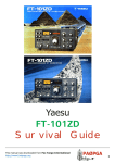
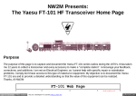
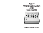
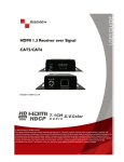
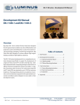
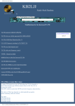
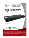
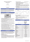
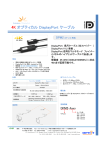
KB2LJJ Radio Mods Database
KB2LJJ
Home
Radio Mods Database and Manuals
Modifications for the Yaesu FT-101
FT-101 series, convet 10 meter to 11 meter
FT-101 series, convet 11 meter to 12 meter
www.r6-ru4montesecchieta.it
IZ5CCV
Replace finals in FT-101E
FT-101 Mod for 30-meter (10MHz)
Transmit
Audio hum in Yaesu FT-101 ZD
CW filter installation for FT-101ZD
Faults FT101zd MK 1,2,3
Click to download the Manual's
FT-101ZD_Filter-Instalation.pdf
FT-101ZD_Manual_and_schematic.pdf
FT-1-1ZD_Service-Manual.pdf
FT-100D Operator Manual.pdf
FT-100D Service Manual.pdf
FT-100D_Spanish Manual.pdf
FT-101_Manual.pdf
FT-101B_Manual.pdf
FT-101b-e_service_v6.pdf
FT-101E_Manual.pdf
FT-101E Schematic and acessories.pdf
FT-101F_Manual.pdf
FT-101 series, convet 10 meter to 11 meter
The mod is to easy, it is certainly useful for the FT 101 series owner.
Conversion to the 11 meter CB band is as simple as replacing one of the 10 meters crystal, that can be 10A 10B
10C 10D or AUXILIARY depend the band you be more interested to keep on 10 meters.
The new 101 radio come with 11 meter, all the new model's have 60M, 80M, 40M, 20M, 15M, 10A, 10B, 10C, 10D, 11M or
AUXILIARY
1 - Open the radio and looking for the crystal's block. The block is close to
the band switch on your right side check it before you doing something. ( Read the manual )
I have one FT-101, 30 years ago, but my is the first series yaesu made. On
http://www.kb2ljj.com/data/yaesu/ft-101.htm (1 di 7)05/09/2009 14:53:00
KB2LJJ Radio Mods Database
my radio I have made the change on 10D for the 11 meters.
2- Replace with a correct crystal. For 27,000 to 27,500 Mhz use the 33.020khz crystal
27,500 to 28,000 Mhz use the 33,520khz crystal
That all folks you radio work now on 11 meters band.
Regards
John
KB2LJJ
FT-101 series, convet 11 meter to 12 meter
Converting 11 Meter band to 12 Meters for the Yaesu FT 101 series ..
Although this procedure hardly qualifies as a "mod" (too easy), it is certainly useful for the FT 101 series owner.
Conversion to the 12 meter WARC band is as simple as replacing a crystal. The 11 meter xtal is replaced with a 30.52 Mhz
3rd overtone xtal in a HC-25/U holder as specified in the FT 101 series maintenance manual. No other modifications are
necessary as the new band is close enough to the original that the current components work. To replace the xtal, remove the
oop cover and find the xtal board located at right front of the rig.
Xtals marked xxxx are standard while oooo are optional on some units. X5, for the 11m, band is an option and may or may
not be installed.
10B
10C
JJY/WWV (1)
160
xxxx
xxxx
xxxx
oooo
xxxx
....
xxxx
xxxx
xxxx
xxxx
oooo
xxxx
80
40
20
15
< X5 the "11 meter" socket
10A
The xtal was ordered from Marden Electronics (800-222-6093) although it is probably available from the other companies
which offer this type of item. I'll skip the business details here, but it is cheap. I found fat fingers a hindrance when yanking
the old and insterting the new so I used a hemostat (narrow nosed locking type device with "seconds" often found in
hardware stores, etc.). After checking with a local ham who monitored my transmissions to make sure I was where I
thought I was, I was in business with 12 meters for my FT 101B.
How'd it go ?? After warming up the rig, I spun the dial a bit on what has been a mostly dead band this summer. The first
station I heard was a little weak .. AA5QC .. no it's A35QC. I had no idea where that was, but I gave him a call. It turned
out to be JF1WQC vacationing in TONGA, my first African contact and a 59 report at that! So here's an easy way to add a
WARC band and open new possibilities for DX adventure with your FT 101 series rig. Please let me know if you have any
additional feedback or comments on what has to be one of the easiest "mods" ever.
(1) This is another story .. note that it is a receive only band for 10 Mhz .. for now. See Page 70 of the Nov 83 issue of 73
Magazine if you can't wait.
http://www.kb2ljj.com/data/yaesu/ft-101.htm (2 di 7)05/09/2009 14:53:00
KB2LJJ Radio Mods Database
Replace finals in FT-101E
There will come a time when the finals in your FT101E will need replacing. These transceivers were originally equipped
with 6JS6C tubes manufactured by NEC.
This tube's properties are slightly different from the 6JS6C tubes available today from American tube manufacturers. By
the way, don't bother looking for tubes made by NEC. They got out of the business several years ago.
In order to use the "American" variety 6JS6's, a simple modification to the neutralization circuit must be made to the final
section of the transceiver.
The modification consists of replacing the fixed value 100 pf 1000 VDC mica capacitor with a 10 pf 1000 VDC mica
capacitor. This capacitor, C125, is in series with the 10 pf variable neutralizing capacitor off of the plate circuit.
If this modification has not already been completed on your rig, be sure to use a mica or silver mica of at least 1000 VDC.
Do not substitute a different type, because the heat in the final compartment will change the value, and your tubes will fail
prematurely. Also, be very careful to keep all leads short and in exactly the same orientation as the original capacitor.
Before reneutralizing, open the variable neutralizing capacitor all the way to minimum engagement and follow the
neutralizing instructions in the manual. While dipping the plate, remember to adjust the neutralizing capacitor for equal
value meter reading peaks (IC position) on both sides of the dip when tuning the "Plate" control.
FT-101 Mod for 30-meter (10MHz) Transmit
I made several of these mods about ten years ago but I am a little fuzzy. The FT101 uses 10mhz for its WWV position but
they left out the driver and final coil connections in the transmit section of the radio. So you either add coils or you can
jump the band switch in the driver portion and the final section.
Connect a jumper from the 20meter driver coil tab, to the WWV driver tab; and the 40 meter final coil tab to the WWV
final tab.
This will make the driver tune in the 40meter position and the final will dip around the 20meter position.
A cheap mod for another band, Good Luck but remember that packet or rtty is continious power so you need to back off the
drive to about 1/3 normal or you will cook the finals!!!!!!
Terry WA6RNF @ Boise,Idaho
Audio hum in Yaesu FT-101 ZD
Author: Jose Miguel Fernandez EA4BQN I have always liked transceivers with tubed final stage, for several reasons, but mainly because it is nice to hear from your
correspondent: - you have a very good modulation, ... it sounds different, ... the tubes' job is noticed.
In addition of that I have to say that tuning these transceivers is not a trouble for me, and also that up to now all the
servicing needed by my3 tubed transceivers ( 2 Yaesu FT-101 ZD and 1 Yaesu FT-102) has been performed by my self.
One day I noticed in one of the Yaesu FT-101 ZD a little hum which could be heard at minimum volume level and when
the radio was switched to transmission with the PTT. Tt wasn't a great trouble but when you want to have things working as
better as possible you are forced to try finding the problem.
http://www.kb2ljj.com/data/yaesu/ft-101.htm (3 di 7)05/09/2009 14:53:00
KB2LJJ Radio Mods Database
The first suspicious were the electrolytic capacitors of the power supply, and they were all replaced by new ones, even the
pair of 200 uF, 500 volt, on the high voltage rectifier, but unfortunately the hum was still there.
Then the following step was to checkthe final audio amplifier located in the PB 1964 af unit, replacing the output module
UPC2002, but no improvement was obtained.
After checkingthe parts around this module I could verify that the problem was in the 2 wire shielded cable connecting the
input of Q01 (UPC2002) to the potentiometer of volume in the front panel.
I desoldered this 2 wire shielded cable at potentiometer end and connect there, two new 1 conductor shielded cables,
soldering together the braids of these wires at the af board end to a good ground point, for instance to a solder lug inserted
in the screw fixing the UPC2002 to the board.
Then I desoldered one end of the resistor R06 4.7 K and the negative end of C07 1uF and soldered there the corresponding
wires from the potentiometer
After this operation the audio hum was removed.
I suppose this hum could be picked up by the original shielded cable along its way to the volume control
Best 73'S
EA4BQN
CW filter installation for FT-101ZD
1. Remove the topcover of the transceiver case, as shown in Fig. 1.
2. Refer to Fig. 2, and locate the NB-FIX circuit board. Remove its mounting screws, because this board is obstructing
the removal of the IF unit.
3. Remove the 12-pin, 13-pin, and 15-pin plugs from their sockets on the IF unit. Remove the IF unit mounting screws,
and remove the IF unit from the transceiver case.
4. Install the optional CW filter as shown in the foil side view of the IF unit (Fig. 3). Make the fastening nuts snug, and
solder the pins of the filter to the circuit board, and remove the 2 jumper wires shown in Figure 3.
5. Re-install the IF unit, being careful to connect the 12-pin, 13-pin, and 15-pin plugs in the correct sockets. Refer to
Fig. 2 to be ure. Re-install the NB-FIX unit, and replace the top cover of the transceiver.
6. When the optional CW filter is installed, the CW-N position of the mode switch will activate this filter. In the CWW position, the SSB 2.4 kHz filter will be in use. The WIDTH control is usable in all modes.
http://www.kb2ljj.com/data/yaesu/ft-101.htm (4 di 7)05/09/2009 14:53:00
KB2LJJ Radio Mods Database
http://www.kb2ljj.com/data/yaesu/ft-101.htm (5 di 7)05/09/2009 14:53:00
KB2LJJ Radio Mods Database
http://www.kb2ljj.com/data/yaesu/ft-101.htm (6 di 7)05/09/2009 14:53:00
KB2LJJ Radio Mods Database
Faults FT101zd MK 1,2,3
Author: ZL3MH On 10 meters the Transmitter takes off on HF or with the tranverters being used. The problem is dry joints or earthing
points around the 12BY7. The fix is to Solder points on and around the 12BY7 printed circuit board.
Fault blows main fuse every 1/2 to up to 6 hours and is not the 6146b's flashing over. There are vertical type caps in PB1988 and the internal fluids run down and ark across the narrow gap in the caps ( screen supply ) ( a common problem in
TV sets ) Replace caps in screen supply PB-1988 C1001,C1002,C1003 and C1004 ,10 uf 450v.
Replace 1000pf from the plate of the driver valve to the grids of the 6146b 's. This is a precautionary measure as the FT101
series had problems here.
The NB stops working sometimes. It appears to be a dry joint on plug pins or the Noise blanker/ crystal lock board . The fix
is to solder around the connections the above printed circuit board.
Fault the RX and the TX stop working except on narrow cw position. The fault was a dry joint on the crystal filter XF01 on
the IF board. I found out that this radio had been used mobile a lot down rough dirt roads. The filters are heavy and in the
center of the PC board so solder around the rest of the filters on the IF board.
The transmitter stops working. The band change switch is in two parts. Its is joined where in goes into the 6146b
compartment from a steel shaft to a fiber shaft. This becomes loose and the bands do not line up properly. It is a good
precaution to mark with a marker pen and tighten the screws on the band change switch extension.
I heard from one FT101zd repairer spending days tracking this one down.
The FT101zd is designed for the FTV901 series of tranverter via the 11 pin ACC socket. The Plate, screen and bias
voltages are not always wired to the ACC socket. This is needed if you want to run the FTV650b 6 meter transverter that is
designed for the earlier FT101 series. Especially the MK3 model did not have the above wiring. Both the FTV250 and
FTV650b can be used with this mod on all FT101zd's.
Modifications and faults collated from around ZL by ZL3MH
http://www.kb2ljj.com/data/yaesu/ft-101.htm (7 di 7)05/09/2009 14:53:00