1
SERVICE MANUAL
DV-AGMD-101599.10
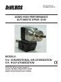
AGMD HIGH PERFORMANCE
AUTOMATIC SPRAY GUN
MODELS:
514 CONVENTIONAL AIR ATOMIZATION
515 HVLP ATOMIZATION
IMPORTANT: Before using this equipment,
carefully read SAFETY PRECAUTIONS, starting
on page 1, and all instructions in this manual.
Keep this Service Manual for future reference.
AGMD Automatic Spray Gun – Contents
CONTENTS
PAGE
SAFETY:
4-5
SAFETY PRECAUTIONS......................................................................................................... 4
HAZARDS / SAFEGUARDS.................................................................................................... 5
INTRODUCTION:6-7
GENERAL DESCRIPTION........................................................................................................
MODELS..................................................................................................................................
SPECIFICATIONS....................................................................................................................
AGMD HIGH PERFORMANCE AUTOMATIC
SPRAY GUN MODEL IDENTIFICATION.................................................................................
6
6
6
INSTALLATION:
7
7
INSTALLATION........................................................................................................................ 7
OPERATION: 8
AIR CAP INSTALLATION........................................................................................................ 8
AGMD-515 HVLP & LVMP ONLY............................................................................................ 8
BACK PRESSURE - 46C AND 83C.......................................................................................... 8
MAINTENANCE:
8
GUN REMOVAL AND INSTALLATION................................................................................... 8
PARTS IDENTIFICATION:
9-17
AGMD PARTS IDENTIFICATION OVERVIEW........................................................................ 9
AGMD-514 CONVENTIONAL ATOMIZATION SPRAY GUN
PARTS IDENTIFICATION / PARTS LIST.................................................................................. 10
AGMD-515 HVLP AND LVMP ATOMIZATION SPRAY GUN
PARTS IDENTIFICATION / PARTS LIST.................................................................................. 11
AGMD-514 CONVENTIONAL AUTOMATIC GUN &
AGMD-515 HVLP AND LVMP AUTOMATIC GUN FLUID TIP,
NEEDLE COMBINATIONS, AIR CAP SELECTION & AIR FLOW CHARTS........................... 12
AGMD-245-1 INTERMEDIATE PLATE
ASSEMBLY / PARTS LIST....................................................................................................... 13
AGMD-251 MACHINE ADAPTER ASSEMBLY /
PARTS LIST............................................................................................................................. 14
(Continued On Next Page)
2
DV-AGMD-101599.10
AGMD Automatic Spray Gun – Contents
CONTENTS (cont.)
PAGE
PARTS IDENTIFICATION (Cont.):
AGMD-279-US60 AND AGMD-279-US90 SINGLE HEAD
ADAPTER VIEWS / PARTS LIST.............................................................................................
AGMD-278-US60 AND AGMD-278-US90 DUAL HEAD
ADAPTER VIEWS / PARTS LIST.............................................................................................
AGMD-514 AND AGMD-515 RECOMMENDED
RECOMMENDED SPARE PARTS / AIR CAP TEST KITS (OPTIONAL)..................................
ACCESSORIES (INDUSTRIAL)...............................................................................................
APPENDIX: 9-17
15
16
17
17
18-21
PAINT AND SOLVENT SPECIFICATIONS.............................................................................. 18
VISCOSITY CONVERSION CHART........................................................................................ 19-20
VOLUMETRIC CONTENT OF HOSE OR TUBE...................................................................... 21
DV-AGMD-101599.10
3
AGMD Automatic Spray Gun – Safety
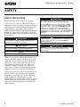
SAFETY
SAFETY PRECAUTIONS
Before operating, maintaining or servicing any
Finishing system, read and understand all of the
technical and safety literature. This manual contains
information that is important for you to know and
understand. This information relates to USER
SAFETY and PREVENTING EQUIPMENT PROBLEMS.
To help you recognize this information, we use the
following symbols. Please pay particular attention to
these sections.
!
WARNING
States information to alert you to a situation that might cause
serious injury if instructions are not followed.
!
Caution
States information that tells how to prevent damage to equipment
or how to avoid a situation that might cause minor injury.
!
WARNING
The user MUST read and be familiar with the Safety Section in this
manual and the DeVilbiss safety literature therein identified.
This manual MUST be read and thoroughly understood by ALL
personnel who operate, clean or maintain this equipment! Special
care should be taken to ensure that the WARNINGS and safety
requirements for operating and servicing the equipment are
followed. The user should be aware of and adhere to ALL local
building and fire codes and ordinances as well as NFPA-33 SAFETY
STANDARD prior to installing, operating, and/or servicing this
equipment.
!
WARNING
The hazards shown on the following page may occur during the
normal use of this equipment. Please read the hazard chart
beginning on page 2.
!
CA PROP 65
WARNING: This product contains chemicals known to the
State of California to cause cancer and birth defects or other
reproductive harm.
NOTE
A NOTE is information relevant to the procedure in progress.
While this manual lists standard specifications and
service procedures, some minor deviations may be
found between this literature and your equipment.
Differences in local codes and plant requirements,
material delivery requirements, etc., make such
variations inevitable. Compare this manual with
your system installation drawings and appropriate
equipment manuals to reconcile such differences.
Careful study and continued use of this manual will
provide a better understanding of the equipment
and process, resulting in more efficient operation,
longer trouble-free service and faster, easier
troubleshooting. If you do not have the manuals and
safety literature for your DeVilbiss system, contact
your local Industrial representative or Automotive
Finishing Group.
4
DV-AGMD-101599.10
AGMD Automatic Spray Gun – Safety
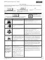
SAFETY PRECAUTIONS
This manual contains information that is important for you to know and understand. This information relates to USER SAFETY and
PREVENTING EQUIPMENT PROBLEMS. To help you recognize this information, we use the following symbols. Please pay particular
attention to these sections.
NOTE
Important safety information – A hazard
that may cause serious injury or loss
of life.
Important information that tells how
to prevent damage to equipment,
or how to avoid a situation that may
cause minor injury.
Information that you should pay special
attention to.
CA PROP
The following hazards may occur during the normal use of this equipment.
Please read the following chart before using this equipment.
65
PROP 65 WARNING
WARNING: This product contains
chemicals known to the State of
California to cause cancer and birth
defects or other reproductive harm.
HAZARD
CAUSE
SAFEGUARDS
Fire
Solvent and coatings can be highly flammable
or combustible especially when sprayed.
Adequate exhaust must be provided to keep air free of
accumulations of flammable vapors.
Smoking must never be allowed in the spray area.
Fire extinguishing equipment must be present in the spray area.
Solvent Spray
During use and while cleaning and flushing,
solvents can be forcefully expelled from fluid
and air passages. Some solvents can cause
eye injury.
Wear eye protection.
Inhaling Toxic Substances
Certain materials may be harmful if inhaled, or
if there is contact with the skin.
Follow the requirements of the Material Safety Data Sheet
supplied by your coating material manufacturer.
Adequate exhaust must be provided to keep the air free of
accumulations of toxic materials.
Use a mask or respirator whenever there is a chance of inhaling
sprayed materials. The mask must be compatible with the material being sprayed and its concentration. Equipment must be
as prescribed by an industrial hygienist or safety expert, and be
NIOSH approved.
Explosion Hazard Incompatible Materials
Halogenated hydrocarbon solvents - for
example; methylene chloride and 1,1,1, Trichloroethane are not chemically compatible
with the aluminum that might be used in many
system components. The chemical reaction
caused by these solvents reacting with
aluminum can become violent and lead to an
equipment explosion.
Guns with stainless steel internal passageways may be used
with these solvents. However, aluminum is widely used in other
spray application equipment - such as material pumps, regulators, valves, and this gun and cup. Check all equipment items before use and make sure they can also be used safely with these
solvents. Read the label or data sheet for the material you intend
to spray. If in doubt as to whether or not a coating or cleaning
material is compatible, contact your material supplier.
General Safety
Improper operation or maintenance of
equipment.
Operators should be given adequate training in the safe use
and maintenance of the equipment (in accordance with the
requirements of NFPA-33, Chapter 15). Users must comply with
all local and national codes of practice and insurance company
requirements governing ventilation, fire precautions, operation,
maintenance, and housekeeping. These are OSHA Sections
1910.94 and 1910.107 and NFPA-33.
Cumulative Trauma
Disorders ("CTD's")
Use of hand tools may cause cumulative
trauma disorders ("CTD's").
Pain, tingling, or numbness in the shoulder, forearm, wrist,
hands, or fingers, especially during the night, may be early
symptoms of a CTD. Do not ignore them. Should you experience
any such symptoms, see a physician immediately. Other early
symptoms may include vague discomfort in the hand, loss of
manual dexterity, and nonspecific pain in the arm. Ignoring early
symptoms and continued repetitive use of the arm, wrist, and
hand can lead to serious disability. Risk is reduced by avoiding
or lessening factors 1-7.
CTD's, or musculoskeletal
disorders, involve damage
to the hands, wrists,
elbows, shoulders, neck,
and back. Carpal tunnel
syndrome and tendonitis
(such as tennis elbow or
rotator cuff syndrome) are
examples of CTD's.
CTD's, when using hand tools, tend to affect the
upper extremities. Factors which may increase
the risk of developing a CTD include:
1. High frequency of the activity.
2. Excessive force, such as gripping, pinching,
or pressing with the hands and fingers.
3. Extreme or awkward finger, wrist, or arm
positions.
4. Excessive duration of the activity.
5. Tool vibration.
6. Repeated pressure on a body part.
7. Working in cold temperatures.
CTD's can also be caused by such activities
as sewing, golf, tennis, and bowling, to name
a few.
DV-AGMD-101599.10
5
AGMD Automatic Spray Gun – Introduction
INTRODUCTION
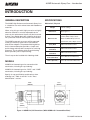
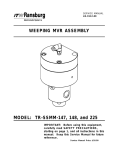
GENERAL DESCRIPTION
SPECIFICATIONS
The AGMD High Performance Automatic Spray Gun
is suitable for use with solvent base and waterborne
materials.
Mechanical / Physical
When using this gun with highly corrosive or highly
abrasive materials it must be expected that the
necessity for replacement of parts will be increased.
If there is any doubt about the suitability of the gun
for a particular material ask the paint manufacturer.
The AGMD automatic spray gun will be mounted
to the gun mover by means of an intermediate
plate and an adapter. The patented locking device
on the intermediate plate provides a simple and
quick change without tools (example: for servicing
purposes). The installation with the quick locking
device provides precise repositioning.
The air cap can be installed with indexing of 90°.
MODELS
Weight
1.33 lbs. (603 g)
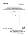
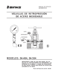
Dimensions
(See Figure 1)
Max. Pressure
Atomizing Air (ATOM) &
Fan Air (FAN) 130 psi (9 bar)
Material (MAT) 200 psi (14 bar)
Cylinder Air (CYL) 100 psi (7 bar)
Spray Head
300 Grade Stainless Steel
Fluid Tip
(Standard)
300 Grade Stainless Steel
Fluid Needle
(Standard)
300 Grade Stainless Steel
Material Contacting
Seals (Standard)
Viton (Waterborne Materials)
Material Contacting
Seals (Optional)
Kalrez (Solvent Base Materials)
AGMD-514: Automatic gun for conventional air
atomization, including air cap indexing.
AGMD-515: Automatic gun for “HVLP” and “LVMP”
atomization, including air cap indexing.
Specify air cap and fluid tip combinations when
ordering (see “Table 1a and 1b” in the “Parts
Identification” section).
514 / 515
1.81”
(46mm)
2.16”
(55mm)
4.96”
(126mm)
1.73”
(44mm)
Figure 1: AGMD-514/515 Dimensions (With AGMD-245-1 Intermediate Plate)
6
DV-AGMD-101599.10
AGMD Automatic Spray Gun – Introduction / Installation
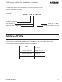
AGMD HIGH PERFORMANCE AUTOMATIC SPRAY GUN
MODEL IDENTIFICATION
When ordering, use AGMD-514 U, FF, or 797C as indicated. Three digits must follow the basic part number,
for example:
AGMD – 514 U 797C FF
Gun Model/ Type/Series
Tip Size (e.g. FF = .055)
With Circulation = U
Air Cap (see “Table 1a and 1b)
Without Circulation = Without U
Installation
1. Firmly screw intermediate plate to adapter and screw adapter to gun mover (robot / reciprocator).
2. Connect compressed air hose and fluid hose machined adapter.
CYL Air
1/8” ID (3.2mm) min.
75 psi min.
FAN Air
(Conventional & HVLP)
Hose lengths up to 15’ (457m)
1/4” ID (6.3mm) min.
ATOM Air
(Conventional & HVLP)
Hose lengths up to 15’ (457m)
1/4” ID min.
Fluid
DV-AGMD-101599.10
1/8” ID (3.2mm) min.
7
AGMD Automatic Spray Gun – Operation / Maintenance
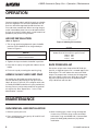
Operation
Connect compressed air and fluid supply to suitable
pressure regulator. For consistent operation the air
pressure should be regulated and be free from oil
mist and water condensate. When securing the gun
to the intermediate plate care must be taken that all
o-rings are in place. Lightly apply a small amount of
petroleum jelly to the o-ring surfaces.
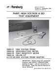
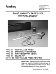
AIR CAP INSTALLATION
(Refer to Figure 2)
Figure 2: Indexing Pin Locations
1. The air cap positioning depends upon the baffle
position. Fit the baffle first on the gun body as
shown in Figure 2.
NOTE
For HVLP operation (max. 10 psi, -0.7 bar cap pressure),
DO NOT exceed the air inlet pressure given as follows:
NOTE
Position 1: Horizontal Pattern
Position 2: Vertical Pattern
PSI (bar) CAP #
25 (1.7) 46C
22 (1.5) 122C
2. Tighten the tip to maintain the baffle in position.
3. Place the air cap by using the two indexes on the
baffle.
4. Fix the air cap by screwing the retaining ring.
AGMD-515 HVLP AND LVMP ONLY
All models are designed to provide maximum
transfer efficiency by limiting air cap pressure to
10 psi (0.7 bar) (in the U.S., this complies with rules
issued by SCAQMD and other air qulity authorities).
Air cap pressure can be measured with an optional
air cap test kit. (See “Spare Parts “ in the “Parts
Identification” section.)
BACK PRESSURE 46C
Due to the unique cone shape of the MP fluid tips
(nozzle), a slight back pressure is created against the
fluid column. This will reduce the amount of fluid
output. To compensate, increase the fluid regulator
pressure slightly if necessary. With 10 psi (0.7 bar)
cap pressure, back pressures are approximately
3.5 psi (0.24 bar) with the 46C.
MAINTENANCE
GUN REMOVAL AND INSTALLATION
1. Relieve system pressure.
2. Press unlocking pin, turn gun by 45° and lift it off
the intermediate plate.
8
3. When installing gun, check o-rings and replace
if necessary. Check for clean surface and holes.
Lubricate o-rings and AGMD-245-1 intermediate
plate with food grade petroleum jelly before
installation.
DV-AGMD-101599.10
AGMD Automatic Spray Gun – Parts Identification
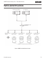
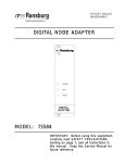
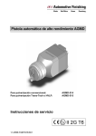
PARTS IDENTIFICATION
Conventional AGMD-514
HVLP AGMD-514
Intermediate Plate
AGMD-245-1
MACHINE ADAPTER
AGMD-251
90° SINGLE ADAPTER
AGMD-279-US90
90° DOUBLE ADAPTER
AGMD-278-US90
60° DOUBLE ADAPTER
AGMD-278-US60
60° SINGLE ADAPTER
AGMD-279-US60
AGMD-278-S SLEEVE INCLUDED WITH ADAPTERS
Figure 3: AGMD Parts Identification Overview
DV-AGMD-101599.10
9
AGMD Automatic Spray Gun – Parts Identification
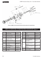
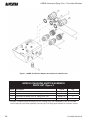
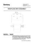
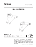
Figure 4: AGMD·514 Conventional Atomization Spray Gun Parts Identification
AGMD-514 CONVENTIONAL ATOMIZATION SPRAY GUN PARTS LIST (Figure 4)
Item #
10
Description
Part #
1
Retaining Ring
MBC-368
2
Air Cap
3
Item #
Description
Part #
13
Piston
AGMD-243-1
See Table 1a
14
Spring
AGMD-111
Fluid Tip (1/2” Hex)
See Table 1a
15
Plate, Rear
AGMD-242
4
Gasket (2 Required)
AGMD-65-1
16
Screw, Set with Slot
AGMD-116
5
Baffle Assembly
(Includes two (2)
AGMD-65-1 Gaskets)
AGMD-33
17
Screw, Spring Plunger
AGMD-115
6
Spray Head
AGMD-195
18
Screw (4 Required),
Hex Head Machined
(5mm Hex)
AGMD-131
7
Locking Device
AGMD-244-1
8
Screw, Socket Head Cap
(4mm Hex)
AGMD-130
O-Ring (5 Required),
Standard Waterborne
Materials
AGMD-119
9
Needle Packing
Assembly (6mm Hex)
AGMD-405-1
79001-27
10
Fluid Needle
See Table 1a
O-Ring (5 Required),
Optional, Solventborne
Materials
11
O-Ring (2 Required)
7554-09
20
Pad, Spring
AGMD-219
12
Gun Body
AGMD-217
21
Pressure Spring
AGMD-110
19
DV-AGMD-101599.10
AGMD Automatic Spray Gun – Parts Identification
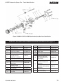
Figure 5: AGMD-515 HVLP & LVMP Atomization Spray Gun Parts Identification
AGMD-515 HVLP AND LVMP ATOMIZATION SPRAY GUN PARTS LIST (Figure 5)
Item #
Description
Part #
1
Retaining Ring
MBC-368
2
Air Cap
3
Description
Part #
13
Piston
AGMD-243-1
See Table 1b
14
Spring
AGMD-111
Fluid Tip (1/2" Hex)
See Table 1b
15
Plate, Rear
AGMD-242
4
Gasket (2 Required)
AGMD-65-1
16
Screw, Set with Slot
AGMD-116
5
Baffle Assembly
(Includes two (2)
AGMD-65-1 Gaskets)
AGMD-34
17
Screw, Spring Plunger
AGMD-115
6
Spray Head
AGMD-195
18
Screw (4 Required),
Hex Head Machined
(5mm Hex)
AGMD-131
7
Locking Device
AGMD-244-1
8
Screw, Socket Head Cap
(4mm Hex)
AGMD-130
O-Ring (5 Required),
Standard Waterborne
Materials
AGMD-119
9
Needle Packing
Assembly (6mm Hex)
AGMD-405-1
79001-27
10
Fluid Needle
See Table 1b
O-Ring (5 Required),
Optional, Solventborne
Materials
11
O-Ring (2 Required)
7554-09
20
Pad, Spring
AGMD-219
12
Gun Body
AGMD-217
21
Pressure Spring
AGMD-110
DV-AGMD-101599.10
Item #
19
11
AGMD Automatic Spray Gun – Parts Identification
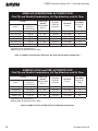
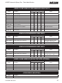
AGMD-514 CONVENTIONAL AUTOMATIC GUN
Fluid Tip and Needle Combinations, Air Cap Selection, and Air Flow
Air Cap
†
‡
Fluid Tip &
Needle‡
AGMD-4000XX ø in.
Viscosity
ZAHN #2
(seconds)
Flow Rate
CC/min.
Fan Width
Inch @ 10”
Target
Part # †
Air Flow
CFM @ psi
Inlet Pressure
AV-1239-765C
22 @ 80
FX / .042
Up to 26
Up to 600
15"
AV-1239-765C
22 @ 80
FF / .055
Up to 28
Up to 900
15"
AV-1239-765C
22 @ 80
E / .070
28+
Up to 1000
15"
AV-1239-797C
21 @ 70
FX / .042
Up to 26
Up to 600
17"
AV-1239-797C
21 @ 70
FF / .055
Up to 28
Up to 900
17"
AV-1239-797C
21 @ 70
E / .070
28+
Up to 1000
17"
Certified air caps marked with “C”
Made of High Grade 303 Stainless Steel
Table 1a: AGMD-514 Conventional Automatic Gun Fluid Tip and Needle Combinations
AGMD-515 HVLP and LVMP AUTOMATIC GUN
Fluid Tip and Needle Combinations, Air Cap Selection, and Air Flow
Air Cap
Air Flow
CFM @ psi
Inlet Pressure
Part # †
†
‡
Fluid Tip &
Needle‡
AGMD-4600XX ø in.
Viscosity
ZAHN #2
(seconds)
Flow Rate
CC/min.
Fan Width
Inch @ 10”
Target
†
AGMD-46C
26.5 @ 70
FX / .042
Up to 26
Up to 200
11"
†
AGMD-46C
26.5 @ 70
FF / .055
Up to 30
Up to 300
11"
†
AGMD-122C
9.5 @ 22
FX / .042
Up to 26
Up to 200
10"
†
AGMD-122C
9.5 @ 22
FF / .055
Up to 30
Up to 300
10"
Certified air caps marked with “C”
Made of High Grade 303 Stainless Steel
Table 1b: AGMD-515 HVLP & LVMP Fluid Tip and Needle Combinations
12
DV-AGMD-101599.10
AGMD Automatic Spray Gun – Parts Identification
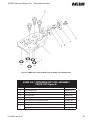
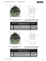
Figure 6: AGMD-245-1 Intermediate Plate Assembly Parts Identification
AGMD-245-1 INTERMEDIATE PLATE ASSEMBLY
PARTS LIST (Figure 6)
Item #
Description
Part #
1
Intermediate Plate
AGMD-147-1
2
Wear Plate
AGMD-346
3
Pressure Piece
AGMD-247
4
Plate
AGMD-246
5
Screw, Socket Pan Head Machined
AGMD-130
6
Screw, (3 Required), Socket Head Cap
AGMD-142
O-Ring, (5 Required), Waterborne
AGMD-119
O-Ring, (5 Required), Solventborne Materials
79001-27
7
DV-AGMD-101599.10
13
AGMD Automatic Spray Gun – Parts Identification
Figure 7: AGMD-251 Machine Adapter Assembly Parts Identification
AGMD-251 MACHINE ADAPTER ASSEMBLY
PARTS LIST (Figure 7)
Item #
Description
Part #
Qty.
1
Adapter
AGMD-151a
1
2
Connector Assembly, Push-In Tubing, 6mm OD
AGMD-126
1
3
Connector Assembly, Push-In Tubing, 5/16” OD
AGMD-127
2
5
Screw, Set
AGMD-117
1
* ZZ-2663 – Fluid Connector Assembly, Push-In Tubing, 5/16” OD X .040 Wall (2) are not included
with kit. May be purchased separately. Contact your Finishing representative or customer service.
14
DV-AGMD-101599.10
AGMD Automatic Spray Gun – Parts Identification
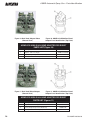
Figure 8: Single Head Adapter Robot
(Bottom View)
Figure 8: AGMD-279-US60 Single Head
Adapter Parts Identification (Top View)
AGMD-279-US60 SINGLE HEAD ADAPTER FOR ROBOT
PARTS LIST (Figure 8)
Item #
Description
Part #
1
Adapter – 60° Face Angle
2
Screw (6 Required), Socket Head Cap
3
Sleeve (Included with adapter)
Figure 9: Single Head Robot Adapter
(Bottom View)
AGMD-279-US60
AGMD-142
AGMD-278-S
Figure 9: AGMD-279-US90 Single Head
Adapter Parts Identification (Top View)
AGMD-279-US90 SINGLE HEAD ADAPTER FOR ROBOT
PARTS LIST (Figure 9)
Item #
DV-AGMD-101599.10
Description
1
Adapter – 90° Face Angle
2
Screw (6 Required), Socket Head Cap
3
Sleeve (Included with adapter)
Part #
AGMD-279-US90
AGMD-142
AGMD-278-S
15
AGMD Automatic Spray Gun – Parts Identification
Figure 10: Dual Head Adapter Robot
(Bottom View)
Figure 10: AGMD-278-US60 Dual Head
Adapter Parts Identification (Top View)
AGMD-278-US60 DUAL HEAD ADAPTER FOR ROBOT
PARTS LIST (Figure 10)
Item #
Description
Part #
1
Adapter – 60° Face Angle
2
Screw (4 Required), Socket Head Cap
3
Sleeve (Included with adapter)
Figure 11: Dual Head Robot Adapter
(Bottom View)
AGMD-278-US60
AGMD-142
AGMD-278-S
Figure 11: AGMD-278-US90 Dual Head
Adapter Parts Identification (Top View)
AGMD-278-US90 DUAL HEAD ADAPTER FOR ROBOT
PARTS LIST (Figures 11)
Item #
16
Description
1
Adapter – 90° Face Angle
2
Screw (4 Required), Socket Head Cap
3
Sleeve (Included with adapter)
Part #
AGMD-278-US90
AGMD-142
AGMD-278-S
DV-AGMD-101599.10
AGMD Automatic Spray Gun – Parts Identification
AGMD-514 AND AGMD-515 RECOMMENDED SPARE PARTS
Part #
Number of Guns
Description
1–5
5–10
10–15
AGMD-110
Pressure Spring
1
1
2
3
AGMD-111
Pressure Spring
1
1
2
3
AGMD-65-1
Fluid Tip Gasket
4
6
8
10
AGMD-244-1
Locking Device
1
2
3
4
Cap Screw
1
2
3
4
Needle Packing
2
3
4
5
O-Ring
1
2
3
4
Piston Assembly
1
2
3
4
O-Ring, Solvent Proof, Kalrez
5
10
15
20
20
AGMD-130
AGMD-405-1
7554-09
AGMD-243-1
79001-27
AGMD-119
MBC-368
O-Ring, Viton (Standard)
5
10
15
Retaining Ring
1
2
3
Notes
15+
For use with solventborne
(Optional) materials.
For use with waterborne paints.
4
AGMD-514 RECOMMENDED SPARE PARTS
Part #
AGMD-33
Number of Guns
Description
1–5
Baffle Assembly
5–10
10–15
Notes
15+
1
1
2
2
AGMD-4000-XX Fluid Tip & Needle Combination
2
3
4
4
Replace XX with FX for .042,
FF for .055, or E for .070
AV-1239-XXXC
2
3
4
5
Replace XXX with 765 or 797.
Air Cap
AGMD-515 RECOMMENDED SPARE PARTS
Part #
AGMD-34
Number of Guns
Description
1–5
Baffle Assembly
AGMD-4600-XX Fluid Tip & Needle Combination
AGMD-XXXX
Air Cap
5–10
10–15
Notes
15+
1
1
2
2
2
3
4
5
Replace XX with FX for .042;
FF for .055 and E for .070.
2
3
4
5
Replace XXX with 46 or 122.
AGMD-514 AND AGMD-515 AIR CAP TEST KITS (OPTIONAL)
Part #
78293-01
Number of Guns
Description
Air Cap Test Kit
1–5
5–10
10–15
1
1
1
Notes
15+
1
For 46C Cap
74035-18
Air Cap Calibrator Kit
1
1
1
1
For 765C Cap
74035-19
Air Cap Calibrator Kit
1
1
1
1
For 797C Cap
74035-20
Air Cap Calibrator Kit
1
1
1
1
For 122C Cap
ACCESSORIES (INDUSTRIAL)
Part #
Description
54-380
Gun Mounting Bar Bracket. (For reciprocator or fixed rod mounting)
DV-AGMD-101599.10
17
AGMD Automatic Spray Gun – Appendix
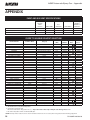
APPENDIX
PAINT AND SOLVENT SPECIFICATIONS
REA™
VECTOR™
EFM™
Evolver™
REM™ / M90™
NO. 2
HAND GUN
TURBODISK™
AEROBELL® II***
AEROBELL®
AEROBELL® 33
RMA-101™
18 TO 30 SEC
18 TO 30 SEC
20 TO 60 SEC
20 TO 60 SEC
20 TO 60 SEC
PAINT ELECTRICAL RESISTANCE**
.1 M TO
.1 M TO
.1 TO 1 M
.1 M TO
.1 M TO
RECOMMENDED DELIVERY (UP TO)
1000 cc/min
1500 cc/min
180 cc/min
1000 cc/min
500 cc/min
RECOMMENDED VISCOSITY USING A ZAHN NO. 2
GUIDE TO USABLE SOLVENT SELECTION
Chemical Name
Common Name
Category
Flash Point††
(TCC)
*CAS
Number
Evap
Rate†
Elec.
Res.**
DICHLOROMETHANE
Methylene Chloride
Chlorinated Solvents
75-09-2
HIGH
14.5
VM & P NAPHTHA
Naptha
Aliphatic Hydrocarbons
65°F
8030-30-6 10
HIGH
ACETONE
Ketones
-18°F
67-64-1
LOW
5.6
METHYL ACETATE
Esters
90°F
79-20-9
LOW
5.3
BENZENE
Aromatic Hydrocarbons
12°F
71-43-2
HIGH
5.1
ETHYL ACETATE
Esters
24°F
141-78-6
MEDIUM
3.9
2-BUTANONE
MEK
Ketones
16°F
78-93-3
MEDIUM
3.8
ISO-PROPYL ACETATE
Esters
35°F
108-21-4
LOW
3.4
ISOPROPYL ALCOHOL
IPA
Alcohols
53°F
67-63-0
LOW
2.5
2-PENTANONE
MPK
Ketones
104°F
107-87-9
MEDIUM
2.5
METHANOL
Methyl Alcohol
Alcohols
50°F
67-56-1
LOW
2.1
PROPYL ACETATE
n-Propyl Acetate
Esters
55°F
109-60-4
LOW
2.1
TOLUOL
Toluene
Aromatic Hydrocarbons
48°F
108-88-3
HIGH
1.9
METHYL ISOBUTYL KETONE
MIBK
Ketones
60°F
108-10-1
MEDIUM
1.6
ISOBUTYL ACETATE
Esters
69°F
110-19-0
LOW
1.5
ETHANOL
Ethyl Alcohol
Alcohols
64-17-5
LOW
1.4
BUTYL ACETATE
Esters
78 ° F
1.0
LOW
123-86-4
ETHYLBENZENE
Aromatic Hydrocarbons
64°F
100-41-4
HIGH
.89
1-PROPANOL
n-Propyl Alcohol
Alcohols
74°F
71-23-8
LOW
.86
2-BUTANOL
sec.-Butyl Alcohol
Alcohols
72°F
78-92-2
LOW
.81
XYLOL
Xylene
Aromatic Hydrocarbons
79°F
1330-02-07 .80
HIGH
AMYL ACETATE
Esters
106°F
628-63-7
MEDIUM
.67
2-METHYLPROPANOL
iso-Butyl Alcohol
Alcohols
82°F
78-83-1
LOW
.62
METHYL AMYL ACETATE
Esters
96°F
108-84-9
LOW
.50
5-METHYL-2-HEXANONE
MIAK
Ketones
96°F
110-12-3
MEDIUM
.50
1-BUTANOL
n-Butyl Alcohol
Alcohols
95°F
71-36-3
LOW
.43
2-ETHOXYETHANOL
Glycol Ethers
164°F
110-80-5
LOW
.38
2-HEPTANONE
MAK
Ketones
102°F
110-43-0
MEDIUM
.40
CYCLOHEXANONE
Ketones
111°F
108-94-1
MEDIUM
.29
AROMATIC-100
SC#100
Aromatic Hydrocarbons
111°F
HIGH
.20
DIISOBUTYL KETONE
DIBK
Ketones
120°F
108-83-8
MEDIUM
.19
1-PENTANOL
Amyl Alcohol
Alcohols
71-41-0
LOW
.15
DIACETONE ALCOHOL
Ketones
133°F
123-42-2
LOW
.12
2-BUTOXYETHANOL
Butyl Cellosolve
Glycol Ethers
154°F
111-76-2
LOW
.07
CYCLOHEXANOL
Alcohols
111°F
108-93-0
LOW
.05
AROMATIC-150
SC#150
Aromatic Hydrocarbons
149°F
HIGH
.004
AROMATIC-200
Aromatic Hydrocarbons
203°F
HIGH
.003
* CAS Number: Chemical Abstract Service Number.
© DeVilbiss All rights reserved. 05/2013
** Electrical Resistance using the Ransburg Meter.
*** Solvent Base Configuration Only.
† Information Obtained From: http://solvdb.ncms.org Evaporation Rate is Based Upon Butyl Acetate Having a Rate of 1.0
†† The lowest temperature at which a volatile fluid will ignite. f
a
s
t
e
r
S
L
O
W
e
r
NOTE: Chart provides resistance and control information that we feel is necessary when using Automotive Finishing equipment.
18
DV-AGMD-101599.10
AGMD Automatic Spray Gun – Appendix
Din Cup 4
Sears
Craftsman Cup
Saybolt
Universal SSU
Krebs Unit KU
GardnerLithographic
Gardner-Holdt
Bubble
Ford Cup 4
Ford Cup 3
60
30
16
10
.15
15
30
12
25
8
A-3
80
34
17
11
Zahn 5
A-4
Zahn 4
5
Zahn 3
20
Zahn 2
11
Zahn 1
27
Fisher 2
10
Fisher 1
DuPony
Parlin 10
.1
Poise
DuPony
Parlin 7
Centipoise
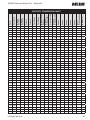
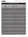
VISCOSITY CONVERSION CHART
.2
20
32
13
30
15
12
10
100
37
18
12
.25
25
37
14
35
17
15
12
A-2
130
41
19
13
.3
30
43
15
39
18
19
14
A-1
160
44
20
.4
40
50
16
50
21
25
18
A
210
52
22
19
15
.5
50
57
17
24
29
22
30
260
60
24
20
16
.6
60
64
18
29
33
25
33
320
68
27
21
18
.7
70
20
33
36
28
35
370
30
23
21
.8
80
22
39
41
31
37
430
34
24
23
B
C
14
.9
90
23
44
45
32
38
480
37
10
26
25
1.0
100
25
50
50
34
D
40
530
41
12
10
27
27
1.2
120
30
62
58
41
E
43
580
49
14
11
31
31
1.4
140
32
66
45
F
46
690
58
16
13
34
34
1.6
160
37
50
G
48
790
66
18
14
38
38
1.8
180
41
54
40
43
2.0
200
45
58
44
46
2.2
220
2.4
240
2.6
260
68
2.8
280
70
3.0
300
74
3.2
320
3.4
340
3.6
360
O
62
3.8
380
4.0
400
P
64
4.2
420
4.4
440
Q
4.6
460
R
4.8
480
5.0
500
S
5.5
550
6.0
600
7.0
700
50
900
74
20
16
H
000
52
1000
82
23
17
10
62
I
54
1100
25
18
11
51
65
J
56
1200
27
20
12
55
58
1280
30
21
13
58
K
59
1380
32
22
14
63
L
60
1475
34
24
15
68
M
1530
36
25
16
72
N
1630
39
26
17
76
1730
41
28
18
82
1850
43
29
19
86
1950
46
30
20
90
2050
48
32
21
95
2160
50
33
22
100
66
2270
52
34
23
104
67
2380
54
36
24
109
68
2480
57
37
25
112
T
69
2660
63
40
27
124
U
71
2900
68
44
30
135
74
3375
51
35
160
00
8.0
800
77
3380
58
40
172
9.0
900
V
81
4300
64
45
195
10.0
1000
W
85
4600
49
218
11.0
1100
88
5200
55
12.0
1200
92
5620
59
DV-AGMD-101599.10
0
19
AGMD Automatic Spray Gun – Appendix
1900
20.0
2000
21.0
2100
9850
22.0
2200
10300
23.0
2300
24.0
2400
25.0
2500
30.0
3000
35.0
3500
40.0
4000
45.0
4500
50.0
5000
23500
55.0
5500
26000
60.0
6000
65.0
6500
30000
70.0
7000
32500
75.0
7500
35000
80.0
8000
37000
85.0
8500
39500
90.0
9000
41000
95.0
9500
43000
98
7000
1600
100
7500
101
8000
100.0 10000
Y
9000
103
Z
2
Z-1
Z-2
3
Z-3
Z-4
Z-5
4
5
9400
105
10750
109
11200
114
11600
121
14500
129
16500
133
18500
136
21000
2800
46500
110.0 11000
51000
55005
130.0 13000
60000
140.0 14000
65000
Z-6
67500
160.0 16000
74000
170.0 17000
83500
180.0 18000
83500
190.0 19000
88000
200.0 20000
93000
300.0 30000
140000
Note: All viscosity comparisons are as accurate as possible with existing information. Comparisons are made with a material having a specific gravity of 1.0.
20
64
8500
120.0 12000
150.0 15000
Din Cup 4
19.0
1500
Sears
Craftsman Cup
1800
6480
Zahn 5
1700
18.0
96
1
Zahn 4
17.0
6100
Zahn 3
16.0
95
Zahn 2
15.0
X
Zahn 1
Saybolt
Universal SSU
Krebs Unit KU
GardnerLithographic
Gardner-Holdt
Bubble
Ford Cup 4
1400
Fisher 2
14.0
Fisher 1
1300
DuPony
Parlin 10
Centipoise
13.0
DuPony
Parlin 7
Poise
Ford Cup 3
VISCOSITY CONVERSION CHART
5/13 ©2013 DeVilbiss All rights reserved.
DV-AGMD-101599.10
AGMD Automatic Spray Gun – Appendix
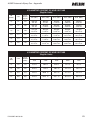
VOLUMETRIC CONTENT OF HOSE OR TUBE
(English Units)
I.D.
(inches)
cc/ft.
Cross
Section
(sq. in.)
1/8
2.4
3/16
Length
5 ft. (60”)
10 ft. (120”)
15 ft. (180”)
25 ft. (300”)
50 ft. (600”)
.012
.003 gal.
.4 fl. oz.
.006 gal.
.8 fl. oz.
.010 gal.
1.2 fl. oz.
.016 gal.
2.0 fl. oz.
.032 gal.
4.1 fl. oz.
5.4
.028
.007 gal.
.9 fl. oz.
.014 gal.
1.8 fl. oz.
.022 gal.
2.8 fl. oz.
.036 gal.
4.6 fl. oz.
.072 gal.
9.2 fl. oz.
1/4
9.7
.049
.013 gal.
1.6 fl. oz.
.025 gal.
3.3 fl. oz.
.038 gal.
4.9 fl. oz.
.064 gal.
8.2 fl. oz.
.127 gal.
16.3 fl. oz.
5/16
15.1
.077
.020 gal.
2.5 fl. oz.
.040 gal.
5.1 fl. oz.
.060 gal.
7.6 fl. oz.
.100 gal.
12.7 fl. oz.
.199 gal.
25.5 fl. oz.
3/8
21.7
.110
.029 gal.
3.7 fl. oz.
.057 gal.
7.3 fl. oz.
.086 gal.
11.0 fl. oz.
.143 gal.
18.4 fl. oz.
.287 gal.
36.7 fl. oz.
1/2
38.6
.196
.051 gal.
6.5 fl. oz.
.102 gal.
13.1 fl. oz.
.153 gal.
19.6 fl. oz.
.255 gal.
32.6 fl. oz.
.510 gal.
65.3 fl. oz.
VOLUMETRIC CONTENT OF HOSE OR TUBE
(English Units)
Length
I.D.
(mm)
cc/m
Cross
Section
(mm2)
1.5 m
3.0 m
4.5 m
6.0 m
7.5 m
3.6
10.2
10.2
15.3 cc
30.5 cc
45.8 cc
61.1 cc
76.3 cc
5.6
24.6
24.6
36.9 cc
73.9 cc
110.8 cc
147.8 cc
184.7 cc
6.8
36.3
36.3
54.5 cc
109.0 cc
163.4 cc
217.9 cc
272.4 cc
8.8
60.8
60.8
91.2 cc
182.5 cc
273.7 cc
364.9 cc
456.2 cc
5/13 ©2013 DeVilbiss All rights reserved.
DV-AGMD-101599.10
21
AGMD Automatic Spray Gun – Appendix
NOTES
22
DV-AGMD-101599.10
AGMD Automatic Spray Gun – Appendix
NOTES
DV-AGMD-101599.10
23
AGMD Automatic Spray Gun
WARRANTY
This product is covered by DeVilbiss’ 1 Year Limited Warranty.
DeVilbiss Sales and Service: www.devilbiss.com
U.S.A./Canada Customer Service
195 Internationale Blvd.
Glendale Heights, IL 60139
630-237-5000
Toll Free Customer Service
and Technical Support
800-992-4657
Toll Free Fax
888-246-5732
5/13 ©2013 DeVilbiss All rights reserved. Printed in U.S.A.