1
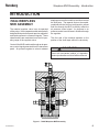
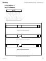
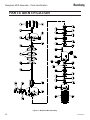
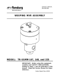
Ransburg SERVICE MANUAL LN-9225-00.5 (Replaces LN-9225-00.4) WEEPLESS MVR ASSEMBLY MODEL: 76624 IMPORTANT: Before using this equipment, carefully read SAFETY PRECAUTIONS, starting on page 1, and all instructions in this manual. Keep this Service Manual for future reference. Service Manual Price: $20.00(U.S.) Weepless MVR Assembly - Safety Ransburg NOTE: This manual has been changed from revision LN-9225-00.4 to revision LN-9225-00.5. Reasons for this change are noted under “Manual Change Summary” inside the back cover of this manual. LN-9225-00.5 Ransburg Weepless MVR Assembly - Safety CONTENTS SAFETY: PAGE 1-5 SAFETY PRECAUTIONS............................................................................................................ 1 HAZARDS / SAFEGUARDS........................................................................................................ 2-5 INTRODUCTION: 6 76624 WEEPLESS MVR ASSEMBLY......................................................................................... 6 MAINTENANCE: 7-10 POSSIBLE CAUSES OF MVR PROBLEMS.............................................................................. PREVENTIVE MAINTENANCE................................................................................................... GENERAL..................................................................................................................................... PRELIMINARY PROCEDURES.................................................................................................. DISASSEMBLY PROCEDURES................................................................................................. VALVE BODY SERVICING......................................................................................................... ASSEMBLY PROCEDURES....................................................................................................... FLUID NEEDLE REPLACEMENT............................................................................................... 7 7 7 8 8 8 8-9 10 PARTS IDENTIFICATION: 11-15 WEEPLESS MVR ASSEMBLY / PARTS LIST............................................................................ 11-12 WEEPLESS MVR ASSEMBLY OPTIONS.................................................................................. 12 RECOMMENDED SPARE PARTS............................................................................................. 13 AVAILABLE TOOLS..................................................................................................................... 13 SERVICE KITS.............................................................................................................................13 77052-00 WEEPLESS MVR SEAL REPLACEMENT KIT.......................................................... 14 77048-00 WEEPLESS MVR SEAL UPGRADE KIT.................................................................... 15 WARRANTY POLICIES: 16 LIMITED WARRANTY.................................................................................................................. 16 APPENDIX: 17-23 PAINT AND SOLVENT SPECIFICATIONS................................................................................ 17 VISCOSITY CONVERSION CHART.......................................................................................... 18-19 VOLUMETRIC CONTENT OF HOSE OR TUBE....................................................................... 20 TECHNICAL BULLETIN: LINE PRESSURE INCREASE DURING TRIGGER-OFF............................................................................................................ 21 76624 WEEPLESS MVR ASSEMBLY / LAFX4001 VALVE ASSEMBLY...................................................................................................................... 22 LN-9225-00.5 Ransburg Weepless MVR Assembly - Safety SAFETY SAFETY PRECAUTIONS Before operating, maintaining or servicing any Ransburg electrostatic coating system, read and understand all of the technical and safety literature for your Ransburg products. This manual contains information that is important for you to know and understand. This information relates to USER SAFETY and PREVENTING EQUIPMENT PROBLEMS. To help you recognize this information, we use the following symbols. Please pay particular attention to these sections. A WARNING! states information to alert you to a situation that might cause serious injury if instructions are not followed. A CAUTION! states information that tells how to prevent damage to equipment or how to avoid a situation that might cause minor injury. A NOTE is information relevant to the procedure in progress. While this manual lists standard specifications and service procedures, some minor deviations may be found between this literature and your equipment. Differences in local codes and plant requirements, material delivery requirements, etc., make such variations inevitable. Compare this manual with your system installation drawings and appropriate Ransburg equipment manuals to reconcile such differences. ! WARNING The user MUST read and be familiar with the Safety Section in this manual and the Ransburg safety literature therein identified. This manual MUST be read and thoroughly understood by ALL personnel who operate, clean or maintain this equipment! Special care should be taken to ensure that the WARNINGS and safety requirements for operating and servicing the equipment are followed. The user should be aware of and adhere to ALL local building and fire codes and ordinances as well as NFPA-33 SAFETY STANDARD, LATEST EDITION, prior to installing, operating, and/or servicing this equipment. ! WARNING The hazards shown on the following pages may occur during the normal use of this equipment. Please read the hazard chart beginning on page 2. Careful study and continued use of this manual will provide a better understanding of the equipment and process, resulting in more efficient operation, longer trouble-free service and faster, easier troubleshooting. If you do not have the manuals and safety literature for your Ransburg system, contact your local Ransburg representative or Ransburg. 1 LN-9225-00.5 Ransburg Weepless MVR Assembly - Safety AREA HAZARD Spray Area Fire Hazard Tells where hazards may occur. Tells what the hazard is. Improper or inadequate operation and maintenance procedures will cause a fire hazard. Protection against inadvertent arcing that is capable of causing fire or explosion is lost if any safety interlocks are disabled during operation. Frequent Power Supply or Controller shutdown indicates a problem in the system requiring correction. SAFEGUARDS Tells how to avoid the hazard. Fire extinguishing equipment must be present in the spray area and tested periodically. Spray areas must be kept clean to prevent the accumulation of combustible residues. Smoking must never be allowed in the spray area. The high voltage supplied to the atomizer must be turned off prior to cleaning, flushing or maintenance. When using solvents for cleaning: •• Those used for equipment flushing should have flash points equal to or higher than those of the coating material. •• Those used for general cleaning must have flash points above 100°F (37.8°C). Spray booth ventilation must be kept at the rates required by NFPA-33, OSHA, country, and local codes. In addition, ventilation must be maintained during cleaning operations using flammable or combustible solvents. Electrostatic arcing must be prevented. Safe sparking distance must be maintained between the parts being coated and the applicator. A distance of 1 inch for every 10KV of output voltage is required at all times. Test only in areas free of combustible material. Testing may require high voltage to be on, but only as instructed. Non-factory replacement parts or unauthorized equipment modifications may cause fire or injury. If used, the key switch bypass is intended for use only during setup operations. Production should never be done with safety interlocks disabled. Never use equipment intended for use in waterborne installations to spray solvent based materials. The paint process and equipment should be set up and operated in accordance with NFPA33, NEC, OSHA, local, country, and European Health and Safety Norms. LN-9225-00.5 2 Ransburg Weepless MVR Assembly - Safety AREA Tells where hazards may occur. Spray Area HAZARD Tells what the hazard is. SAFEGUARDS Tells how to avoid the hazard. Explosion Hazard Improper or inadequate operation and maintenance procedures will cause a fire hazard. Protection against inadvertent arcing that is capable of causing fire or explosion is lost if any safety interlocks are disabled during operation. Frequent Power Supply or Controller shutdown indicates a problem in the system requiring correction. Electrostatic arcing must be prevented. Safe sparking distance must be maintained between the parts being coated and the applicator. A distance of 1 inch for every 10KV of output voltage is required at all times. Unless specifically approved for use in hazardous locations, all electrical equipment must be located outside Class I or II, Division 1 or 2 hazardous areas, in accordance with NFPA-33. Test only in areas free of flammable or combustible materials. The current overload sensitivity (if equipped) MUST be set as described in the corresponding section of the equipment manual. Protection against inadvertent arcing that is capable of causing fire or explosion is lost if the current overload sensitivity is not properly set. Frequent power supply shutdown indicates a problem in the system which requires correction. Always turn the control panel power off prior to flushing, cleaning, or working on spray system equipment. Before turning high voltage on, make sure no objects are within the safe sparking distance. Ensure that the control panel is interlocked with the ventilation system and conveyor in accordance with NFPA-33, EN 50176. Have fire extinguishing equipment readily available and tested periodically. General Use and Maintenance Improper operation or maintenance may create a hazard. Personnel must be given training in accordance with the requirements of NFPA-33, EN 60079-0. Personnel must be properly trained in the use of this equipment. Instructions and safety precautions must be read and understood prior to using this equipment. Comply with appropriate local, state, and national codes governing ventilation, fire protection, operation maintenance, and housekeeping. Reference OSHA, NFPA-33, EN Norms and your insurance company requirements. 3 LN-9225-00.5 Ransburg AREA Tells where hazards may occur. Spray Area / High Voltage Equipment Weepless MVR Assembly - Safety HAZARD Tells what the hazard is. SAFEGUARDS Tells how to avoid the hazard. Electrical Discharge There is a high voltage device that can induce an electrical charge on ungrounded objects which is capable of igniting coating materials. Inadequate grounding will cause a spark hazard. A spark can ignite many coating materials and cause a fire or explosion. Parts being sprayed and operators in the spray area must be properly grounded. Parts being sprayed must be supported on conveyors or hangers that are properly grounded. The resistance between the part and earth ground must not exceed 1 meg ohm. (Refer to NFPA-33.) Operators must be grounded. Rubber soled insulating shoes should not be worn. Grounding straps on wrists or legs may be used to assure adequate ground contact. Operators must not be wearing or carrying any ungrounded metal objects. When using an electrostatic handgun, operators must assure contact with the handle of the applicator via conductive gloves or gloves with the palm section cut out. NOTE: REFER TO NFPA-33 OR SPECIFIC COUNTRY SAFETY CODES REGARDING PROPER OPERATOR GROUNDING. All electrically conductive objects in the spray area, with the exception of those objects required by the process to be at high voltage, must be grounded. Grounded conductive flooring must be provided in the spray area. Always turn off the power supply prior to flushing, cleaning, or working on spray system equipment. Unless specifically approved for use in hazardous locations, all electrical equipment must be located outside Class I or II, Division 1 or 2 hazardous areas, in accordance with NFPA-33. LN-9225-00.5 4 Ransburg Weepless MVR Assembly - Safety AREA Tells where hazards may occur. Electrical Equipment HAZARD Tells what the hazard is. Tells how to avoid the hazard. Electrical Discharge An electrical arc can ignite coating materials and cause a fire or explosion. Unless specifically approved for use in hazardous locations, the power supply, control cabinet, and all other electrical equipment must be located outside Class I or II, Division 1 and 2 hazardous areas in accordance with NFPA-33 and EN 50176. Turn the power supply OFF before working on the equipment. Test only in areas free of flammable or combustible material. Testing may require high voltage to be on, but only as instructed. Production should never be done with the safety circuits disabled. Before turning the high voltage on, make sure no objects are within the sparking distance. Certain material may be harmful if inhaled, or if there is contact with the skin. Follow the requirements of the Material Safety Data Sheet supplied by coating material manufacturer. High voltage equipment is utilized in the process. Arcing in the vicinity of flammable or combustible materials may occur. Personnel are exposed to high voltage during operation and maintenance. Protection against inadvertent arcing that may cause a fire or explosion is lost if safety circuits are disabled during operation. Frequent power supply shutdown indicates a problem in the system which requires correction. Toxic Substances SAFEGUARDS Adequate exhaust must be provided to keep the air free of accumulations of toxic materials. Use a mask or respirator whenever there is a chance of inhaling sprayed materials. The mask must be compatible with the material being sprayed and its concentration. Equipment must be as prescribed by an industrial hygienist or safety expert, and be NIOSH approved. Spray Area Explosion Hazard – Incompatible Materials Halogenated hydrocarbon solvents for example: methylene chloride and 1,1,1,-Trichloroethane are not chemically compatible with the aluminum that might be used in many system components. The chemical reaction caused by these solvents reacting with aluminum can become violent and lead to an equipment explosion. 5 Aluminum is widely used in other spray application equipment - such as material pumps, regulators, triggering valves, etc. Halogenated hydrocarbon solvents must never be used with aluminum equipment during spraying, flushing, or cleaning. Read the label or data sheet for the material you intend to spray. If in doubt as to whether or not a coating or cleaning material is compatible, contact your coating supplier. Any other type of solvent may be used with aluminum equipment. LN-9225-00.5 Ransburg Weepless MVR Assembly - Introduction INTRODUCTION 76624 WEEPLESS MVR ASSEMBLY The material regulator valve is an air-operated sliding valve. It has a tapered needle and specially designed fluid ports that permit precise regulation and rapid response to command signals. These characteristics are maintained over the full operating range of the regulator valve. Control of the MVR is achieved through an air pressure control signal generated from the transducer panel. Air pressure against a solvent resistant diaphragm moves the needle up and down across the fluid ports. The tapered seat on the needle, combined with the fluid port configuration, allows fluid flow through the MVR to directly reflect the air pressure control signal. An increase in air pressure results in an increase in fluid flow through the regulator. The flow rate of the material depends on the position of the shaft taper within the valve body. ! CAUTION IT IS NOT recommended this product be used with isocyanate catalyst or degraded product performance or failure will be observed. > Figure 1: 76624 Weepless MVR Assembly LN-9225-00.5 6 Ransburg Weepless MVR Assembly - Maintenance MAINTENANCE POSSIBLE CAUSES OF MVR PROBLEMS Weekly 1. Most problems with the material regulator are caused by improperly filtered fluid. Particulates and residue in the material regulator can cause plugging of the fluid ports and sluggish valve oper-ation. If repeated disassembly and cleaning for removal of solids and residue occurs, inspect the entire fluid supply system. 2500 Hours of Operation 2. Fluid backup, i.e. reverse flow, can cause reacted/catalyzed material to enter the material regulator. Reverse flow will be detected by the 2-K and the system will shut down, however the material regulator should be cleaned or flush-ed immediately to prevent the fluid from setting-up. 3. Replace the compression spring. If repeated cleaning is required, inspect the check valves and adjust the REV FLOW parameter accordingly. 1.Work from a clean, dry bench. 3. Kinks or tight bends in the control air line may restrict air flow to the material regulator. Inspect the condition of exposed tubing periodically and check the fitting connection at the material regulator. 4. Check the leakage port for any signs of coagulated material. Excessive buildup will cause the valve to operate improperly. Buildup can also indicate that the valve needle and valve body should be replaced. Flush the coating material from the system. Rebuild the valve: 1. Inspect the fluid section and fluid needle. Replace both if excessive leakage is evident. 2. Replace the air diaphragms. 4. Replace the seals (use seal kit 77052-00). GENERAL 2. Always install new o-rings, gaskets and diaphragms when the material regulator is re-assembled. 3. Use only lint-free wipers/cloths for cleaning. 4. Refer to the model number of the material regulator when ordering replacement parts. PREVENTIVE MAINTENANCE Daily 1. Check the leakage ports for fluid leakage. If fluid leakage is evident, repair at earliest opportunity. 2. Inspect the exposed fluid and air tubing for kinks, tight bends, leaks, etc. 7 LN-9225-00.5 Ransburg Weepless MVR Assembly - Maintenance PRELIMINARY PROCEDURES Prior to removing the material regulator for service or repair, perform the following: 1. Flush the material regulator with the system purge. 2. Remove pressure from the affected fluid line. 3. Close the shut-off valves on either side of the material regulator. Diaphragm Removal 1. Remove the allen screw from the diaphragm end of the needle assembly and lift off the flat washer. 2. Remove the diaphragm flat washers and regulator spring. The diaphragm is constructed of (3) layers of PTFE material. It should be replaced if fluid has leaked into the air pressure chamber or the diaphragm shows signs of wear. Fluid Section Disassembly Procedures 4. Clean the exterior of the material regulator before loosening any fittings. 1. Loosen the bottom (4) housing bolts to remove the 76619-00, fluid section, and 76622-00, bottom section. 5. Disconnect the control air line from the material regulator. Cover the exposed hose end to prevent contamination. 2. Thread the 76629-00, piston removal tool, into each of the 77055-00, guide bushings, and pull gently to remove. 6. Remove the material regulator from the fluid line. 7. If the fluid lines will be left open during the repair, cover them to prevent contaminants from entering the fluid system. DISASSEMBLY PROCEDURES Material Regulator Disassembly 1. Clamp the regulator in a bench vise with padded jaws. 2. Loosen the top (4) housing bolts equally and alternately. 3. Lift off the upper housing and remove the diaphragm and needle assembly. VALVE BODY SERVICING Remove the fittings/adapters from the inlet and outlet ports of the valve and clean out any coating build up. ASSEMBLY PROCEDURES Needle Pre-assembly 1. Assemble the TR-SSF-506, small washer, onto the 8301-16C, screw. The radius side of the washer should be facing away from the screw head. 2. Now assemble the (3) TR-SSMM-151, diaphragms, onto the 8301-16C, cap screws, and then place the TR-SSF-505, large washer, on top of the diaphragms. NOTE > As the bolts are loosened, the load spring will force the housing halves apart. Keep equal tension on the housing bolts to avoid damaging the internal components. LN-9225-00.5 8 Ransburg Weepless MVR Assembly - Maintenance 3. Apply a small drop of 7969-031, adhesive (blue), onto the cap screw and assemble onto the 76623-xx, needle. Tighten the needle using the appropriate Allen wrenches. For exact assembly detail, see Figure 3. Guide Bushing Pre-assembly (Refer to Figures 4 & 5) 1. Locate the (2) 77055-00, guide bushings, and assemble (2) 76626, o-rings, and (2) 76625, PTFE back-up rings, onto each guide bushing. 2. Locate (2) 77051-00, seals, one for each guide bushing, and press the seals into the guide bushings. The o-ring side of the seal should be facing out once pressed into the guide bushing. 3. Locate (2) 77050-00, o-rings, and install in the guide bushings. 4. Locate (2) 77049-00, back-up rings, and install in the guide bushings, directly behind the 7705000, o-rings. 5. If no compatibility issues exist with the coating material, apply a generous amount of petroleum jelly on and between the 77050-00, o-rings, and 77051-00, u-cup seals. 6. Install the 77057-00, seal retainer assembly, onto each of the guide bushings, as shown. 7. After assembling the guide bushings, sparingly lubricate the O.D. of the busings with petroleum jelly. Fluid Section to Bottom Section Assembly 1. Assemble the 76621, bottom section, onto the 76619, fluid section, and also onto the 76622, bottom housing. Make sure to align the roll pin into the 76621, bottom section. 2. Once the roll pin is aligned, apply "Blue Adhesive" to the (4) 7959-112C, screws, and screw loosely in place. Do not tighten down screws until all (4) screws have been assembled into the 76621, bottom section, then tighten in an "X" pattern. NOTE > The weep hole in the 76622, bottom housing, must be aligned as shown in Figure 3. Final Body Assembly 1. Place the A10231-00, spring, into the 76621, housing. Now obtain the 76623-xx, needle assembly, and apply a light coat of petroleum jelly onto the assembly. Carefully slide the needle into the 76621, body, and down through the 76619, fluid section. Only a light pushing force is needed. 2. After the needle is seated, obtain the 76618, top section, and place it on top of the TR-SSMM-151, diaphragms. Assemble the (4) 8532-40C, screws, into the 76618, top section, and tighten in an "X" pattern. Fluid Section Pre-assembly 1. Lubricate sparingly, the two bores in the body, with petroleum jelly. 2. Once lubricated, press in the assembled guide bushings. The two threaded holes in the bushing should be facing out from the 76619, fluid section. (See Figures 4 & 5.) 9 LN-9225-00.5 Ransburg Weepless MVR Assembly - Maintenance FLUID NEEDLE REPLACEMENT NOTE > When replacing MVR fluid needles, use Figure 2 below and Weepless MVR Assembly "Part Number Options Chart / Column C" in the "Parts Identification" section to determine the correct size and part number. The number of grooves at the top of the needle correlates to the dash number of the part number. 76623-02 / Low Flow Fluid Needle 76623-03 / Medium Flow Fluid Needle 76623-04 / High Flow Fluid Needle Figure 2: Weepless MVR Fluid Needles LN-9225-00.5 10 Weepless MVR Assembly - Parts Identification Ransburg PARTS IDENTIFICATION Figure 3: Weepless Mvr Assembly 11 LN-9225-00.5 Ransburg Weepless MVR Assembly - Parts Identification WEEPLESS MVR ASSEMBLY - PARTS LIST (Figure 3) Item # 1 2 3 4 5 6 7 8 9 10 11 12 13 14 15 16 17 18 19 20 21 22 23 24 25 26 27 28 Part # 8532-40C 41-FTP-1006 76618-00 41-FP-1006 8301-16C TR-SSF-506 TR-SSMM-151 TR-SSF-505 C* A10231-00 SS-1532-CD 8156-24C 7734-07 7486-07 76621-00 77057-00 77049-00 77050-00 76625-00 76626-00 77055-00 77051-00 21132-027 76619-00 LSFI0033-00 76628-00 76622-00 7959-112C 31881-101 Description Qty Screw, 5/16-18 UNC x 1.25 Long, Steel Socket Head Fitting, 1/8 NPT x 5/32 O.D. Tube Elbow Upper Membrane Housing, Machined, Weepless MVR Plug, 1/8 NPT, Brass Pipe Screw, #8-32 UNC x 1/2 Long, Steel Socket Head Washer, Machined, Upper Diaphragm Support Air Diaphragm, MVR Assembly Washer, Machined, Lower Diaphragm Support Fluid Needle, Machined, Weepless MVR Compression Spring, MVR Screw, 5/16-18 UNC x 1.5 Long, Steel Hex Head Screw, 5/16-18 UNC x 1.75 Long, Steel Hex Head Lock Washer, 5/16 Helical Spring Flat Washer, 5/16 Lower Membrane Housing, Machined, Weepless MVR Seal Retainer Assembly, Weepless MVR Back-Up Ring for 2-109 O-Ring, High Pressure O-Ring, .299 I.D. x .103 c/s, Solvent Proof Back-Up Ring for 2-020 O-Ring, High Pressure O-Ring, .864 I.D. x .070 c/s, Solvent Proof Guide Bushing, Machined, Weepless MVR Seal, O-Ring Loaded U-Cup Pin, 3/16 Diameter x 1 Long Roll Fluid Section, Machined, Weepless MVR Fitting, 3/8 AN Flare x 3/8 O.D. Tube, Stainless Adapter, 3/8 AN Flare x 3/8 O.D. Stem, Stainless Bottom Section, Machined, Weepless MVR Screw, 1/4-20 UNC x 3.5 Long, Steel Socket Head Label, Ransburg 4 D* 1 1 1 1 3 1 1 1 2 2 2 2 1 2 2 2 4 4 2 2 1 1 E* F* 1 4 1 * See corresponding column in Part Number Options below. WEEPLESS MVR ASSEMBLY - PART NUMBER OPTIONS Part # 76624-02 76624-02A 76624-02B 76624-03 76624-03A 76624-03B 76624-04 76624-04A 76624-04B LN-9225-00.5 Description Low Flow Assembly With No Fittings Low Flow Assembly (2) 3/8 O.D. Tube Fittings Low Flow Assembly (1) 3/8 O.D. Tube Fitting and (1) 3/8 O.D. Stem Adapter Medium Flow Assembly With No Fittings Medium Flow Assembly (2) 3/8 O.D. Tube Fittings Medium Flow Assembly (1) 3/8 O.D. Tube Fitting and (1) 3/8 O.D. Stem Adapter High Flow Assembly With No Fittings High Flow Assembly (2) 3/8 O.D. Tube Fittings High Flow Assembly (1) 3/8 O.D. Tube Fitting and (1) 3/8 O.D. Stem Adapter C D E 76623-02 76623-02 76623-02 0 1 1 0 2 1 0 0 1 76623-03 76623-03 76623-03 0 1 1 0 2 1 0 0 1 76623-04 76623-04 76623-04 0 1 1 0 2 1 0 0 1 F 12 Weepless MVR Assembly - Parts Identification Ransburg RECOMMENDED SPARE PARTS Part # Description Qty TR-SSMM-151 A10231-00 77049-00 77050-00 76625-00 76626-00 77051-00 Air Diaphragm, MVR Assembly Compression Spring, MVR Back-Up Ring for 2-109 O-Ring, High Pressure O-Ring, .299 I.D. x .103 c/s, Solvent Proof Back-Up Ring for 2-020 O-Ring, High Pressure O-Ring, .864 I.D. x .070 c/s, Solvent Proof Seal, O-Ring Loaded U-Cup 3 1 2 2 4 4 2 AVAILABLE TOOLS Part # Description 76629-00 Tool, Piston Removal SERVICE KITS 13 Part # Description 77052-00 Kit, Weepless MVR Seal Replacement 77048-00 Kit, Weepless MVR Seal Upgrade LN-9225-00.5 Ransburg Weepless MVR Assembly - Parts Identification Detail D A - All seals must be installed with o-rings toward the needle taper (inward), as shown. B - Lightly lubricate o-rings with petroleum jelly before installing guide bushings into housing. C - A generous amount of petroleum jelly, on and between the o-ring and u-cup seals, may improve the long term performance, if no compatibility issues exist with the coating material. Figure 4: 77052-00 Weepless MVR Seal Replacement Kit 77052-00 WEEPLESS MVR SEAL REPLACEMENT KIT (Figure 4) Item # 1 2 3 4 5 LN-9225-00.5 Part # 77049-00 77050-00 76625-00 76626-00 77051-00 Description Back-Up Ring for 2-109 O-Ring, High Pressure O-Ring, .299 I.D. x .103 c/s, Solvent Proof Back-Up Ring for 2-020 O-Ring, High Pressure O-Ring, .864 I.D. x .070 c/s, Solvent Proof Seal, O-Ring Loaded U-Cup Qty 2 2 4 4 2 14 Weepless MVR Assembly - Parts Identification Ransburg A - All seals must be installed with o-rings toward the needle taper (inward), as shown. B - Lightly lubricate o-rings with petroleum jelly before installing guide bushings into housing. C - A generous amount of petroleum jelly, on and between the o-ring and u-cup seals, may improve the long term performance, if no compatibility issues exist with the coating material. Figure 5: 77048-00 Weepless MVR Seal Upgrade Kit 77048-00 WEEPLESS MVR SEAL UPGRADE KIT (Figure 5) Item # 1 2 3 4 5 6 7 15 Part # 77057-00 77049-00 77050-00 76625-00 76626-00 77055-00 77051-00 Description Seal Retainer Assembly, Weepless MVR Back-Up Ring for 2-109 O-Ring, High Pressure O-Ring, .299 I.D. x .103 c/s, Solvent Proof Back-Up Ring for 2-020 O-Ring, High Pressure O-Ring, .864 I.D. x .070 c/s, Solvent Proof Guide Bushing, Machined, Weepless MVR Seal, O-Ring Loaded U-Cup Qty 2 2 2 4 4 2 2 LN-9225-00.5 Ransburg Weepless MVR Assembly - Warranty Policies WARRANTY POLICIES LIMITED WARRANTY Ransburg will replace or repair without charge any part and/or equipment that falls within the specified time (see below) because of faulty workmanship or material, provided that the equipment has been used and maintained in accordance with Ransburg's written safety and operating instructions, and has been used under normal operating conditions. Normal wear items are excluded. THE USE OF OTHER THAN RANSBURG APPROVED PARTS, VOIDS ALL WARRANTIES. SPARE PARTS: One hundred and eighty (180) days from date of purchase, except for rebuilt parts (any part number ending in "R") for which the warranty period is ninety (90) days. EQUIPMENT: When purchased as a complete unit, (i.e., guns, power supplies, control units, etc.), is one (1) year from date of purchase. WRAPPING THE APPLICATOR IN PLASTIC, SHRINK-WRAP, ETC., WILL VOID THIS WARRANTY. THIS WARRANTY IS TO REPLACE PARTS THAT HAVE FAILED BECAUSE OF FAULTY WORKMANSHIP OR MATERIALS. THERE ARE NO IMPLIED WARRANTIES NOR WARRANTIES OF EITHER MERCHANT ABILITY OR FITNESS FOR A PARTICULAR PURPOSE. RANSBURG ASSUMES NO LIABILITY FOR INJURY, DAMAGE TO PROPERTY OR FOR CONSEQUENTIAL DAMAGES FOR LOSS OF GOODWILL OR PRODUCTION OR INCOME, WHICH RESULT FROM USE OR MISUSE OF THE EQUIPMENT BY PURCHASER OR OTHERS. EXCLUSIONS: If, in Ransburg's opinion the warranty item in question, or other items damaged by this part was improperly installed, operated or maintained, Ransburg will assume no responsibility for repair or replacement of the item or items. The purchaser, therefore will assume all responsibility for any cost of repair or replacement and service related costs if applicable. FLUID HANDLING: One (1) year from date of purchase (i.e., Totalizer, CCV Valves, etc.). AIR BEARING ROTATORS: Fifteen thousand (15,000) hours or three (3) years, whichever occurs first. Warranty period begins on the date of purchase. RANSBURG'S ONLY OBLIGATION UNDER LN-9225-00.5 16 Ransburg Weepless MVR Assembly - Appendix APPENDIX PAINT AND SOLVENT SPECIFICATIONS RECOMMENDED VISCOSITY USING A ZAHN NO. 2 PAINT ELECTRICAL RESISTANCE** RECOMMENDED DELIVERY (UP TO) REATM EVOLVER™ EFMTM EVOLVERTM REMTM / M90TM NO. 2 HAND GUN TURBODISKTM AEROBELL® II*** AEROBELL® AEROBELL® 33 RMA-101TM 18 TO 30 SEC .1 MW TO ∞ 1000 cc/min 18 TO 30 SEC .1 MW TO ∞ 1500 cc/min 20 TO 60 SEC .1 TO 1 MW 180 cc/min 20 TO 60 SEC .1 MW TO ∞ 1000 cc/min 20 TO 60 SEC .1 MW TO ∞ 500 cc/min GUIDE TO USABLE SOLVENT SELECTION Chemical Name DICHLOROMETHANE VM & P NAPHTHA ACETONE METHYL ACETATE BENZENE ETHYL ACETATE 2-BUTANONE ISO-PROPYL ACETATE ISOPROPYL ALCOHOL 2-PENTANONE METHANOL PROPYL ACETATE TOLUOL METHYL ISOBUTYL KETONE ISOBUTYL ACETATE ETHANOL BUTYL ACETATE ETHYLBENZENE 1-PROPANOL 2-BUTANOL XYLOL AMYL ACETATE 2-METHYLPROPANOL METHYL AMYL ACETATE 5-METHYL-2-HEXANONE 1-BUTANOL 2-ETHOXYETHANOL 2-HEPTANONE CYCLOHEXANONE AROMATIC-100 DIISOBUTYL KETONE 1-PENTANOL DIACETONE ALCOHOL 2-BUTOXYETHANOL CYCLOHEXANOL AROMATIC-150 AROMATIC-200 Common Name Category Methylene Chloride Chlorinated Solvents Naptha Aliphatic Hydrocarbons Ketones Esters Aromatic Hydrocarbons Esters MEK Ketones Esters IPA Alcohols MPK Ketones Methyl Alcohol Alcohols n-Propyl Acetate Esters Toluene Aromatic Hydrocarbons MIBK Ketones Esters Ethyl Alcohol Alcohols Esters Aromatic Hydrocarbons n-Propyl Alcohol Alcohols sec.-Butyl Alcohol Alcohols Xylene Aromatic Hydrocarbons Esters iso-Butyl Alcohol Alcohols Esters MIAK Ketones n-Butyl Alcohol Alcohols Glycol Ethers MAK Ketones Ketones SC#100 Aromatic Hydrocarbons DIBK Ketones Amyl Alcohol Alcohols Ketones Butyl Cellosolve Glycol Ethers Alcohols SC#150 Aromatic Hydrocarbons Aromatic Hydrocarbons * CAS Number: Chemical Abstract Service Number. ** Electrical Resistance using the Ransburg Meter. *** Solvent Base Configuration Only. † Information Obtained From: http://solvdb.ncms.org †† The lowest temperature at which a volatile fluid will ignite. Evaporation Rate is Based Upon Butyl Acetate Having a Rate of 1.0 Flash Point†† (TCC) 65oF -18oF 90oF 12oF 24oF 16oF 35oF 53oF 104oF 50oF 55oF 48oF 60oF 69oF 78oF 64oF 74oF 72oF 79oF 106oF 82oF 96oF 96oF 95oF 164oF 102oF 111oF 111oF 120oF 133oF 154oF 111oF 149oF 203oF *CAS Number 75-09-2 8030-30-6 67-64-1 79-20-9 71-43-2 141-78-6 78-93-3 108-21-4 67-63-0 107-87-9 67-56-1 109-60-4 108-88-3 108-10-1 110-19-0 64-17-5 123-86-4 100-41-4 71-23-8 78-92-2 1330-02-07 628-63-7 78-83-1 108-84-9 110-12-3 71-36-3 110-80-5 110-43-0 108-94-1 108-83-8 71-41-0 123-42-2 111-76-2 108-93-0 Evap. Rate† 14.5 10 5.6 5.3 5.1 3.9 3.8 3.4 2.5 2.5 2.1 2.1 1.9 1.6 1.5 1.4 1.0 .89 .86 .81 .80 .67 .62 .50 .50 .43 .38 .40 .29 .20 .19 .15 .12 .07 .05 .004 .003 F A S T E R S L O W E R Elec. Res.** HIGH HIGH LOW LOW HIGH MEDIUM MEDIUM LOW LOW MEDIUM LOW LOW HIGH MEDIUM LOW LOW LOW HIGH LOW LOW HIGH MEDIUM LOW LOW MEDIUM LOW LOW MEDIUM MEDIUM HIGH MEDIUM LOW LOW LOW LOW HIGH HIGH © 2013 Ransburg. All rights reserved. NOTE: Chart provides resistance and control information that we feel is necessary when using Ransburg equipment. 17 LN-9225-00.5 Ransburg Weepless MVR Assembly - Appendix 11 20 30 12 25 Sears Craftsman Cup 10 17 11 Din Cup 4 16 34 Zahn 5 30 80 Zahn 4 60 Zahn 3 Gardner Lithographic Krebs Unit KU Gardner Holdt Bubble Ford Cup 4 Ford Cup 3 5 A-4 8 A-3 Zahn 2 27 15 Zahn 1 10 Saybolt Universal SSU .1 .15 Fisher 2 Fisher 1 Parlin 10 Parlin 7 Centipoise Poise VISCOSITY CONVERSION CHART .2 20 32 13 30 15 12 10 100 37 18 12 .25 25 37 14 35 17 15 130 41 19 13 .3 30 43 15 39 18 19 12 A-2 14 A-1 160 44 20 14 .4 40 50 16 50 21 25 18 .5 50 57 17 24 29 22 .6 60 64 18 29 33 25 .7 70 20 33 36 28 .8 80 22 39 41 31 .9 90 23 44 45 32 1.0 100 25 50 50 34 1.2 120 30 62 58 1.4 140 32 66 1.6 160 37 50 1.8 180 41 54 2.0 200 45 58 H 2.2 220 62 2.4 240 65 2.6 260 68 2.8 280 70 3.0 300 74 3.2 320 3.4 340 3.6 360 3.8 380 4.0 400 4.2 210 52 22 19 15 30 260 60 24 20 16 33 320 68 27 21 18 35 370 30 23 21 37 430 34 24 23 38 480 37 10 26 25 D 40 530 41 12 10 27 27 41 E 43 580 49 14 11 31 31 45 F 46 690 58 16 13 34 34 G 48 790 66 18 14 38 38 50 900 74 20 16 40 43 52 1000 82 23 17 10 44 46 I 54 1100 25 18 11 51 J 56 1200 27 20 12 55 A B C 000 58 1280 30 21 13 58 K 59 1380 32 22 14 63 L 60 1475 34 24 15 68 M 1530 36 25 16 72 N 1630 39 26 17 76 1730 41 28 18 82 1850 43 29 19 86 1950 46 30 20 90 420 2050 48 32 21 95 4.4 440 Q 2160 50 33 22 100 4.6 460 R 66 2270 52 34 23 104 4.8 480 67 2380 54 36 24 109 5.0 500 S 68 2480 57 37 25 112 5.5 550 T 69 2660 63 40 27 124 6.0 600 U 71 2900 68 44 30 135 7.0 700 74 3375 51 35 160 8.0 800 77 3380 58 40 172 9.0 900 V 81 4300 64 45 195 10.0 1000 W 85 4600 49 218 11.0 1100 88 5200 55 12.0 1200 92 5620 59 LN-9225-00.5 O 62 P 64 00 0 18 Ransburg Weepless MVR Assembly - Appendix 1800 19.0 1900 20.0 2000 21.0 2100 9850 22.0 2200 10300 23.0 2300 24.0 2400 25.0 2500 30.0 3000 35.0 3500 40.0 4000 45.0 4500 50.0 5000 55.0 5500 60.0 6000 65.0 6500 30000 70.0 7000 32500 75.0 7500 35000 80.0 8000 37000 85.0 8500 39500 90.0 9000 41000 95.0 9500 100.0 10000 7500 101 8000 Y 64 8500 9000 103 Z 2 Z-1 Z-2 3 Z-3 9400 105 10750 109 11200 114 11600 121 14500 129 16500 133 18500 136 21000 23500 26000 Z-4 4 2800 43000 Z-5 5 46500 110.0 11000 51000 120.0 12000 55005 130.0 13000 60000 140.0 14000 150.0 15000 Din Cup 4 18.0 7000 100 Sears Craftsman Cup 1700 6480 98 Zahn 5 17.0 96 Zahn 4 1600 6100 Zahn 3 16.0 1 95 Zahn 2 1500 X Zahn 1 Saybolt Universal SSU Gardner Lithographic Krebs Unit KU Gardner Holdt Bubble Ford Cup 4 15.0 Fisher 2 1400 Fisher 1 1300 14.0 Parlin 10 Centipoise 13.0 Parlin 7 Poise Ford Cup 3 VISCOSITY CONVERSION CHART (Continued) 65000 Z-6 67500 160.0 16000 74000 170.0 17000 83500 180.0 18000 83500 190.0 19000 88000 200.0 20000 93000 300.0 30000 140000 Note: All viscosity comparisons are as accurate as possible with existing information. Comparisons are made with a material having a specific gravity of 1.0. © 2013 Ransburg. All rights reserved. 19 LN-9225-00.5 Ransburg Weepless MVR Assembly - Appendix VOLUMETRIC CONTENT OF HOSE OR TUBE (English Units) I.D. (inches) cc/ft. Cross Section (in.2) 1/8 2.4 .012 3/16 5.4 .028 1/4 9.7 .049 5/16 15.1 .077 3/8 21.7 .110 1/2 38.6 .196 Length 5ft. (60") .003 gal. .4 fl. oz. .007 gal. .9 fl. oz. .013 gal. 1.6 fl. oz. .020 gal. 2.5 fl. oz. .029 gal. 3.7 fl. oz. .051 gal. 6.5 fl. oz. 10ft. (120") 15ft. (180") 25ft. (300") 50ft. (600") .006 gal. .8 fl. oz. .014 gal. 1.8 fl. oz. .025 gal. 3.3 fl. oz. .040 gal. 5.1 fl. oz. .057 gal. 7.3 fl. oz. .102 gal. 13.1 fl. oz. .010 gal. 1.2 fl. oz. .022 gal. 2.8 fl. oz. .038 gal. 4.9 fl. oz. .060 gal. 7.6 fl. oz. .086 gal. 11.0 fl. oz. .153 gal. 19.6 fl. oz. .016 gal. 2.0 fl. oz. .036 gal. 4.6 fl. oz. .064 gal. 8.2 fl. oz. .100 gal. 12.7 fl. oz. .143 gal. 18.4 fl. oz. .255 gal. 3.6 fl. oz. .032 gal. 4.1 fl. oz. .072 gal. 9.2 fl. oz. .127 gal. 16.3 fl. oz. .199 gal. 25.5 fl. oz. .287 gal. 36.7 fl. oz. .510 gal. 65.3 fl. oz. VOLUMETRIC CONTENT OF HOSE OR TUBE (Metric Units) I.D. (mm) cc/m Cross Section (mm2) 1.5m 3.0m 4.5m 6.0m 7.5m 3.6 10.2 10.2 15.3 cc 30.5 cc 45.8 cc 61.1 cc 76.3 cc 5.6 24.6 24.6 36.9 cc 73.9 cc 110.8 cc 147.8 cc 184.7 cc 6.8 36.3 36.3 54.5 cc 109.0 cc 163.4 cc 217.9 cc 272.4 cc 8.8 60.8 60.8 91.2 cc 182.5 cc 273.7 cc 364.9 cc 456.2 cc Length © 2013 Ransburg. All rights reserved. LN-9225-00.5 20 Ransburg Weepless MVR Assembly - Appendix Ransburg Technical Bulletin Subject:Line Pressure Increase During Trigger-Off -See 76624 Weepless MVR Assembly / LAFX4001 Valve Assembly The 76624 Weepless MVR Assembly is designed to be a replacement for the TR-SSMM-XXX “Weeping” MVR Assembly. In some installations, the elimination of the weep port has resulted in an excessive line pressure increase during the trigger-off time. The result is a burst of fluid immediately after the applicator is triggered-on. This situation is most likely to occur when low viscosity fluids are supplied to the Weepless MVR Assembly at high fluid pressures. If this condition occurs and the fluid supply pressure is less than 300 psi, it is recommended that an LAFX4001 Valve Assembly be installed between the fluid supply pump and Weepless MVR Assembly. Please find the attached sketch. This valve can then be used as a preliminary shut-off valve to interrupt the fluid pressure to the Weepless MVR Assembly. By delaying the trigger-off at the applicator, the line pressure can be minimized to eliminate the surging at initial trigger-on. Note that the LAFX4001 valve should be triggered at the same time as the gun is triggered. Also note that if the system already has a color valve stack existing, the color valve in the stack can be used to accomplish these same results. 21 LN-9225-00.5 Ransburg Weepless MVR Assembly - Appendix 76624 Weepless MVR Assembly / LAFX4001 Valve Assembly LN-9225-00.5 22 Weepless MVR Assembly - Manual Change Ransburg MANUAL CHANGE SUMMARY This manual was published to replace Service Manual LN-9225-00.4, Weepless MVR Assembly, to make the following changes: 1. Revised "Figure 4: 77052 Weepless MVR Seal Replacement Kit" in the "Parts Identification" section. 2. Revised "Figure 5: 77048-00 Weepless MVR Seal Upgrade Kit" in the "Parts Identification" section. 3. Revised "Volumetric Content of Hose or Tube" Charts (English & Metric Units) in the "Appendix" section. 4. Update "Contact Information" on the "Back Cover." 23 LN-9225-00.5 Service Manual Price: $20.00 (U.S.) Manufacturing 1910 North Wayne Street Angola, Indiana 46703-9100 Telephone: 260/665-8800 Fax: 260/665-8516 Technical/Service Assistance Telephone: 800/ 233-3366 Fax: 419/ 470-2071 Technical Support Representative will direct you to the appropriate telephone number for ordering Spare Parts. © 2013 Ransburg. All rights reserved. Models and specifications subject to change without notice. Form No. LN-9225-00.5 Litho in U.S.A. 04/13