1
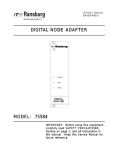
SERVICE MANUAL
TE-98-01.5 - September 2006
(Replaces TE-98-01.4)
PAINT
TAGE & SCI
AINT,, HIGH VOL
VOLT
TEST EQUIPMENT
76652-01
76652-02
76652-03
76652-04
A1
1757-00
A11757-00
HIGH VOL
TAGE PROBE
VOLT
SPRA
YABILITY/SCI METER
SPRAY
PAINT RESISTIVITY METER
DELUXE KIT
HIGH VOL
TAGE PROBE ADAPTER
VOLT
IMPOR
TANT
IMPORT
ANT:: Before using this equipment,
carefully read SAFETY PRECAUTIONS,
starting on page 1, and all instructions in
this manual. Keep this Service Manual for
future reference.
Service Manual Price: $30.00 (U.S.)
N O T E : This manual has been changed from revision TE-98-01.4 to revision TE-98-01.5
TE-98-01.5.
Reasons for this change are noted under “Manual Change Summary” inside the back
cover of this manual.
TE-98-01.5
Paint, High Voltage & SCI Test Equipment - Contents
CONTENTS
SAFETY:
PAGE
1 - 3
SAFETY PRECAUTIONS........................................................................................................... 1
HAZARDS/SAFEGUARDS......................................................................................................... 2-3
TEST EQUIPMENT:
5-17
MULTI-FUNCTION ELECTROSTATIC METER........................................................................
SPRAYABILITY, SCI, AND RESISTANCE
MEASUREMENT KIT..................................................................................................................
PAINT RESISTANCE MEASUREMENT KIT.............................................................................
HIGH VOLTAGE MEASUREMENT KIT.....................................................................................
GENERAL MAINTENANCE.......................................................................................................
5-6
WARRANTY POLICIES:
19
7-12
12-13
14-16
17
LIMITED WARRANTY................................................................................................................. 19
APPENDIX:
20-23
PAINT AND SOLVENT SPECIFICATIONS............................................................................... 20
VISCOSITY CONVERSION CHART......................................................................................... 21-22
VOLUMETRIC CONTENT OF HOSE OR TUBE...................................................................... 23
TE-98-01.5
Paint, High Voltage & SCI Test Equipment - Safety
SAFETY
SAFETY PRECAUTIONS
Before operating, maintaining or servicing any
ITW Ransburg coating system, read and
understand all of the technical and safety literature
for your ITW Ransburg products. This manual
contains information that is important for you to
know and understand. This information relates to
USER SAFETY and PREVENTING EQUIPMENT
PROBLEMS. To help you recognize this
information, we use the following symbols. Please
pay particular attention to these sections.
A WARNING! states information to alert you
to a situation that might cause serious injury
if instructions are not followed.
A CAUTION! states information that tells
how to prevent damage to equipment or how
to avoid a situation that might cause minor
injury.
A NOTE is information relevant to the
procedure in progress.
While this manual lists standard specifications
and service procedures, some minor deviations
may be found between this literature and your
equipment. Differences in local codes and plant
requirements, material delivery requirements, etc.,
make such variations inevitable. Compare this
manual with your system installation drawings
and appropriate ITW Ransburg equipment
manuals to reconcile such differences.
! WARNING
The user MUST read and be familiar
with the Safety Section in this manual and
the ITW Ransburg safety literature therein
identified.
>
> This manual MUST be read and thoroughly understood by ALL personnel who
operate, clean or maintain this equipment!
Special care should be taken to ensure that
the WARNINGS and safety requirements
for operating and servicing the equipment
are followed. The user should be aware of
and adhere to ALL local building and fire
codes and ordinances as well as NFPA-33
SAFETY STANDARD, prior to installing,
operating, and/or servicing this equipment.
! WARNING
> The hazards shown on the following
page may occur during the normal use of
this equipment. Please read the hazard
chart beginning on page 2.
Careful study and continued use of this manual will
provide a better understanding of the equipment
and process, resulting in more efficient operation,
longer trouble-free service and faster, easier
troubleshooting. If you do not have the manuals
and safety literature for your Ransburg system,
contact your local ITW Ransburg representative
or ITW Ransburg.
1
TE-98-01.5
Paint, High Voltage & SCI Test Equipment - Safety
AREA
HAZARD
SAFEGUARDS
Tells where hazards
Tells what the hazard is.
Tells how to avoid the hazard.
may occur.
Spray Area
Electrostatic Arcing
Never operate the spray gun without properly
grounding the following:
A. Operators
Operators must be grounded. Rubber soled
insulating shoes should not be worn. Grounding
leg straps may be used.
Operators must maintain contact with the handle
of the gun. If work gloves are used, the palm
section should be cut out.
Operators must remove from themselves all
metal objects that are not grounded.
NOTE: REFER TO NFPA-33 REGARDING
OPERATOR GROUNDING
B. Parts being sprayed. Resistance between the
part and a grounded conveyor must not exceed 1
megohm.
C. Every metal and conductive object in the spray
area. This includes the booth, parts hangers, fire
extinguishers, conductive flooring, etc.
Grounded conductive flooring must be provided in
the spray area.
Turn off voltage at the power supply before flushing
out, cleaning, or removing any parts from the gun.
Provide proper protection for waterborne supply
systems.
Never install a spray gun into a fluid system using an
isolated solvent supply.
Always discharge Waterborne system capacitance
prior to servicing.
Do not touch gun electrode while gun is energized.
TE-98-01.5
2
Paint, High Voltage & SCI Test Equipment - Safety
AREA
HAZARD
SAFEGUARDS
Tells where hazards
Tells what the hazard is.
Tells how to avoid the hazard.
may occur.
Toxic Substances
Certain materials may be
harmful if inhaled or if there is
contact with the skin.
Follow the requirements of the Material Safety Data
Sheet supplied by your coating material
manufacturer.
Adequate exhaust must be provided to keep the air
free of accumulations of toxic materials.
Use a mask or respirator whenever there is a
chance of inhaling sprayed materials. The mask
must be compatible with the material being sprayed
and its concentration. Equipment must be as
prescribed by an industrial hygienist or safety
expert, and be NIOSH approved.
General Use and
Maintenance
Improper operation or
maintenance may create a
hazard.
Personnel must be properly
trained in the use of this
equipment.
3
Personnel must be given training in accordance
with the requirements of NFPA-33.
Instructions and safety precautions must be read
and understood prior to using this equipment.
Comply with appropriate local, state, and national
codes governing ventilation, fire protection,
operation, maintenance, and housekeeping.
Reference OSHA, NFPA-33, and your insurance
company requirements.
TE-98-01.5
Paint, High Voltage & SCI Test Equipment - Safety
NOTES
TE-98-01.5
4
Paint, High Voltage & SCI Test Equipment
MUL
TI-FUNCTION
MULTI-FUNCTION
ELECTROST
ATIC METER
ELECTROSTA
The ITW Ransburg Multi-Function Electrostatic
Spray Meter uses one meter to serve multifunctions in electrostatic spray finishing. The
meter can be used to measure conductivity, paint
resistance, short circuit current, resistance, and
high voltage. The meter is available in individual
kits focused on each function or a deluxe kit,
which includes accessories to perform all the
functions listed above.
The ITW Ransburg Multi-Function Electrostatic
Spray Meter is powered by a single 9V alkaline
battery. The solid state circuitry only requires 9V
input to power the meter display and condition all
the signals from the accessory items.
Part #
Description
76652-01 Kit for measuring high voltage.
Includes 76634-00 Multi-Function
Meter and 76667 High Voltage
Probe Assembly.
76652-02
Kit for measuring short circuit current (SCI),resistance and sprayability.
Includes 76634-00 Multi-Function
Meter and 76664-00 Test Lead Assembly.
76652-03
Kit for measuring paint resistivity.
Includes 76634-00 Multi-Function
Meter and 7922-00 Paint Probe
Assembly.
76652-04
Deluxe Kit
Performs all functions listed above.
Includes 76634-00 Multi-Function
Meter, 7922-00 Paint Probe Assembly, 76664-00 Test Lead Assembly,
and 76667-00 High Voltage Probe
Assembly.
A11757-00 High Voltage Probe Adapter
Adapter to measure the voltage
coming from an individual probe
(electrode) assembly on RMA-303
Indirect Charge Robot Mounted
Rotary Atomizer (A11600, A11300),
Aerobell 2.5 Indirect Charge
(A10924), and Aerobell II Indirect
Charge (77603).
Meter Scale Ranges:*
kV: 0 to ±199.9 kVDC
μA: 0 to ±1999 μA
kΩ: 1 to 1999 kΩ (.001 to 1.999 MΩ)
MΩ: 00.1MΩ to 199.9 MΩ
GΩ: .1GΩ to 19.99 GΩ
* Note: For readings below 2 MΩ, more resolution can be obtained by using the kΩ scale.
5
TE-98-01.5
Paint, High Voltage & SCI Test Equipment
Figure 1A: Multi-Function Meter
Figure 1B: Multi-Function Meter Kit Parts
TE-98-01.5
6
Paint, High Voltage & SCI Test Equipment
SPRA
YABILITY
SPRAY
ABILITY,, SCI,
AND RESIST
ANCE
RESISTANCE
MEASUREMENT KIT
Sprayability
The Sprayability Meter measures whether
materials normally considered being electrically
non-conductive could be electrostatically sprayed
or whether they need to be treated with solutions
to make the surface conductive. The meter
measures the surface resistance and indicates
the degree of sprayability in MΩ or GΩ. The target
being sprayed must be low enough in resistance
to dissipate the electrostatic charge. In some
cases the internal resistance of a target is lower
than the surface resistance. This might allow a
target that does not have a suitable surface
resistance reading to be coated electrostatically
without additional surface preparation. An example
of this is certain types of wood which on the
surface are not conductive but due to moisture
content (12%-13%) may be sprayable.
Since many non-conductive products must be
pre-treated with a conductive solution to make
them sprayable, the ITW Ransburg Multi-Function
Electrostatic Spray Meter is useful to monitor and
maintain consistency in that application, once a
suitable reading is determined.
!
and re-perform the check. If the meter still does
not read zero, consult the factory for repair of the
meter.
2. With the metallic part of the meter probes
pressed firmly and perpendicular against the
surface of the article to be tested, the meter
automatically reads the resistance of the part.
Table 1 lists the readings from an 8333-00 meter
and compares it to the readings of the MultiFunction Meter.
Meter Readings
0Ω to 1.0G
Ω - The article is suitable for spraying
1.0GΩ
using the electrostatic process.
1.0G
Ω to 1.5G
Ω - The article is questionable for
1.0GΩ
1.5GΩ
spraying using the electrostatic process. In such
cases, paint a trial sample article to determine if a
conductive primer or conductive solution for the
part surface is required.
1.5G
Ω to Infinity - The article is NOT suitable
1.5GΩ
for spraying. A conductive primer or conductive
solution is required to treat the surface of the part.
CAUTION
> Ensure that meter's scale is properly set
for the function in which it is being used.
Damage to equipment may result if improperly
set.
Operation
1. Set the meter dial to the MΩ or GΩ scale (see
Figure 2). Check the meter calibration by touching
the metallic end of the two (2) probes on the meter
to the stripped bare ends of a single 12" long wire
(see Figure 2). (If desired the continuity of the wire
may be verified by using a Volt-Ohm meter). If the
meter reads zero, the meter is in calibration. If it
does not read zero, verify the continuity of the wire
7
Figure 2: Sprayability Test Meter
TE-98-01.5
Paint, High Voltage & SCI Test Equipment
New 76652-01 Multi-Function
Meter Reading
1 MΩ
8333-00 Sprayability
Meter Reading
155
Spray Condition
Suitable
2 MΩ
150
Suitable
3 MΩ
147
Suitable
4 MΩ
145
Suitable
14 MΩ
140
Suitable
60 MΩ
135
Suitable
190 MΩ or .1 GΩ
130
Suitable
320 MΩ or .3 GΩ
125
Suitable
410 MΩ or .4 GΩ
120
Suitable
500 MΩ or .5 GΩ
115
Suitable
600 MΩ or .6 GΩ
110
Suitable
760 MΩ or .7 GΩ
105
Suitable
1020 MΩ or 1.0 GΩ
100
Suitable
1.1 GΩ
98
Test Sample Part
1.3 GΩ
95
Test Sample Part
1.5 GΩ
90
Test Sample Part
2.0 GΩ to Infinity
85 or less
Requires Surface Prep
Table 1: Comparison to 8333-00 Sprayability Meter with
New Multi-Function Meter
TE-98-01.5
8
Paint, High Voltage & SCI Test Equipment
Resistance/T
esting
Resistance/Testing
Target/Product Ground
The ITW Ransburg Multi-Function Meter may be
used to measure approximate resistance in kΩ,
MΩ, or GΩ. Applications for the meter range from
measuring the resistance of a 70430-XX resistor
to measuring the resistance of a target to ground.
!
CAUTION
> Ensure that meter's scale is properly set
for the function in which it is being used.
Damage to equipment may result if improperly
set.
Operation
1. Set the meter dial to the MΩ scale (see Figure
3). Plug the probe with two (2) alligator clamp
leads into the side of the meter. Check the meter
calibration by touching the metallic ends of the two
(2) probes together. If the meter reads zero, the
meter is in calibration. If it does not read zero,
verify the continuity of the probe assembly and reperform the check. If the meter still does not read
zero, consult the factory for repair of the meter.
2. For ground checks, attach one alligator clip to
a clean, non-treated surface of the target to be
sprayed. Attach the other alligator clip to a known
true earth ground. Set the dial to the MΩ scale.
Read the resistance. If the resistance is greater
than 1.0 MΩ the part is not adequately grounded
(reference NFPA-77, NFPA-33).
NOTE
> When using the Multi-Function Meter
test leads to measure resistance or current, ensure that the sprayability probes
do not come into contact with any surface
or the meter readings may be altered.
! WARNING
> If the reading between true earth ground
and the target is greater than 1.0 MΩ, then
the hooks, racks, supports, etc. must be
cleaned and eventually demonstrate a true
earth ground resistance of 1.0 MΩ or lower.
See NFPA-33 for further information.
3. For resistance checks, set the meter to MΩ
scale (see Figure 4). Attach one alligator clip to the
electrode wire of a 70430-XX screwed onto a
needle shaft (or similar component). Attach the
other lead to the shaft of the needle shaft (or other
end of a similar component). The electrode reading
should be approximately 14.5 MΩ to 19MΩ.
Figure 3:
9
Calibration Check Resistance
TE-98-01.5
Paint, High Voltage & SCI Test Equipment
!
CAUTION
> Ensure that meter's scale is properly set
for the function in which it is being used.
Damage to equipment may result if improperly
set.
Operation
! WARNING
> Prior to starting the SCI tests, ensure the
voltage at the power supply is turned off.
1. Set the meter dial to the μA scale (see Figure
5). Plug the probe with two (2) alligator clamp
leads into the side of the meter. Ensure the meter
reads zero. If it does not read zero, consult the
factory for repair of the meter.
Figure 4: Measuring Electrode Resistance
Short Circuit Current-SCI
(Power Supplies)
The ITW Ransburg Multi-Function Meter may be
used to measure the short circuit current of an
electrostatic product. The short circuit current
measurement is important in troubleshooting
problems with electrostatic power supplies and
applicators. These tests should be performed
when a noticeable decrease in transfer efficiency
occurs. The measured short circuit current value
should be compared to the value listed in the
appropriate power supply or applicator manual.
This comparison indicates if there are problems
with the power source or the applicator.
TE-98-01.5
2. Place appropriate test resistor (see Table 2) in
the high voltage cable socket of the power supply.
Be sure it is pushed clear to the bottom or proper
contact will not be made. Attach one of the alligator
clamps to the lead of the test resistor. Attach the
other alligator clamp to a known true earth ground.
Turn the power supply on. Then trigger H.V. by the
air flow switch or jumper as required by gun model.
(See appropriate service manual for further
information.) Be sure that the power supply lights
indicate that high voltage is being generated.
Measure and record the short circuit current from
the meter. This value should be compared to the
value listed in the appropriate power supply service
manual. A brief listing of ITW Ransburg power
supply short circuit current readings is listed in
Table 3.
10
Paint, High Voltage & SCI Test Equipment
Short Circuit Current-SCI
(Guns)
The ITW Ransburg Multi-Function Meter may be
used to measure the short circuit current of an
electrostatic applicator. The short circuit current
measurement is important in troubleshooting
problems with electrostatic power supplies and
applicators. These tests should be performed
when a noticeable decrease in transfer efficiency
occurs. The measured short circuit current value
should be compared to the value listed in the
appropriate power supply or applicator manual.
This comparison indicates if there are problems
with the power source or the applicator.
!
2. Attach one of the alligator clamps to the
electrode (brush on the #2 process bell). Be sure
the clamp makes good contact with the electrode
(small wires on the #2 brush). Attach the second
alligator clamp to ground, preferably the handle or
bracket.
3. Apply voltage to the gun from the power supply.
The meter should read between the ranges
indicated in Table 3. Consult power supply and
applicator manuals for readings outside these
ranges.
CAUTION
> Ensure that meter's scale is properly set
for the function in which it is being used.
Damage to equipment may result if improperly
set.
Operation
! WARNING
> Prior to starting the SCI tests, ensure the
voltage at the power supply is turned off.
1. Set the meter dial to the μA scale (see Figure
5). Plug the probe with two (2) alligator clamp
leads into the side of the meter. Check the meter
calibration by touching the metallic ends of the two
(2) probes together. If the meter reads zero, the
meter is in calibration. If it does not read zero,
verify the continuity of the probe assembly and reperform the check. If the meter still does not read
zero, consult the factory for repair of the meter.
11
Figure 5:
Testing SCI on Power Supplies
Resistor
Part No.
16688-01
R e s i s t a n c e Power Supply
Ω
for Use With
MΩ
In M
160
Dry Paks, Porta
Paks, 9040 Classic
Power Supplies
REA-III, REA-IV,
REM Classic
16688-02
525
All #2 Power
Supplies
Table 2. SCI Test Resistors and Power
Supplies
TE-98-01.5
Paint, High Voltage & SCI Test Equipment
Power Supply
SCI Range
in μA
79344-XXX, 9050 Classic,
Vector R90/70
140 μA
76447-10X, 9040 Classic, REA-IV
100-150 μA
76447-11X, 9040 Classic,
REM Classic
75-100 μA
76447-12X, 9040 Classic,
REAIII Hand
100-150 μA
76447-13X, 9040 Classic,
REAIII Auto
125-175 μA
76657-14X, 9040 Classic, No. 2 Gun
75-110 μA
76304-02,-04, Dry-Pak, REAIV, REH 200-225 μA
70918-01, Porta-Pak, REAIII Hand
160-200 μA
70394-02, Porta-Pak, REAIII Auto
170-220 μA
19219-02, 70360-01, Porta-Pak, No. 2 80-100 μA
Table 3. Power Supplies and SCI Values
PAINT RESIST
ANCE
RESISTANCE
MEASUREMENT KIT
Paint Resistivity
The ITW Ransburg Paint Resistance Measurement Kit using the multi-function meter is designed
to provide measurement of the electrical resistance
of paint formulations for all electrostatic
applications. Once the resistance of a paint is
determined and found to spray successfully,
measuring resistivity with this meter provides a
way to duplicate conditions. This is extremely
important when troubleshooting problems with
spray or rotational applicators. This meter has two
(2) scales, MΩ and kΩ that may be used for
measurement of the paint resistance.
TE-98-01.5
!
CAUTION
>
Testing Metallic Paint
In certain paint formulations where materials
of appreciable content of metal flake or
powder (i.e., aluminum, bronze, or metallic
colors) are used, this method of testing
resistance can be misleading or inconclusive.
This paint tester will NOT indicate the metallic
content of the formula.
Whenusing the paint tester with metallic paints,
the low voltage battery of the test probe may
not be enough to influence the metal particles,
therefore, their presence may go unrecognized by the meter. When such formulations
are placed in electrostatic applicators and
high voltage applied, the metal particles may
become aligned by the electrical field. This
may result in an appreciable increase of
current flow to ground by way of the pain
delivery system. While the flow of current
poses no immediate dangerous condition, it
may drain some or all of the voltage from the
electrode and may reduce or eliminate
electrostatic efficiency.
!
CAUTION
> Ensure that meter's scale is properly set
for the function in which it is being used.
Damage to equipment may result if improperly
set.
12
Paint, High Voltage & SCI Test Equipment
Meter Readings
Table 4 lists the ranges of paint resistivity that
work best for specific ITW Ransburg applicators.
Applicator
Paint Resistivity
Range
Aerobell, Aerobell 33, Disks 0.05 MΩ to 1.0MΩ
#2 Process Handgun
0.1 MΩ to 1.0MΩ
Vector, REA, or REM guns 0.1 MΩ to Infinity
Table 4. Paint Resistivity Ranges *
Figure 6:
Paint Tester Operation
Operation
1. Set the meter dial to the MΩ scale (see Figure
6). Plug the paint probe into the side of the meter.
2. Immerse the probe vertically into a well-mixed
representative sample of the subject paint until the
holes at the bottom of the slots in the probe sleeve
are submerged (see Figure 6). Take a reading
within 5 to 10 seconds of submerging the probe.
!
CAUTION
> Do not immerse the paint probe past the
top of the sleeve.
*Use this table as a guideline. Usually a trial for
resistance above listed values is recommended.
When resistance is below listed values,
electrostatic effect will be reduced due to a
higher current draw to ground. To spray this
material may require other means of increasing
distance to ground such as adding coiled fluid
tubes.
To obtain MΩ - CM from the resistance in MΩ
from the meter, multiply by 132.
MΩ - CM = MΩ reading X 132
(Ref. ASTM D5628)
Maintenance
The test probe MUST be cleaned IMMEDIATELY
after each use. Use a suitable solvent and clean
cloth to thoroughly clean the probe assembly.
1. Remove the probe sleeve and clean it inside
and out, removing all paint residues (it may be
soaked while probe is cleaned).
2. Thoroughly clean the outside of the probe with
the cloth and solvent.
!
CAUTION
> NEVER soak the paint probe. There is no
solvent seal at the point where the handle
screws into the body of the probe. If solvent
is allowed to enter at this point or where the
cable enters at the top of the handle, the
interior wiring will deteriorate and have to be
replaced.
3. Place the cleaned sleeve back on the probe.
13
TE-98-01.5
Paint, High Voltage & SCI Test Equipment
HIGH VOL
TAGE
VOLT
MEASUREMENT KIT
High V
oltage Measurement
Voltage
The ITW Ransburg High Voltage Measurement
Kit using the multi-function meter is designed to
provide measurement of high voltage DC potential
for all electrostatic applicators to 200kV. Having
an accurate measurement of output voltage from
an applicator is very important when troubleshooting problems with an installation. The reading
from this device indicates whether the applicator
and power supply are operating correctly. This kit
comes with the following accessories:
1. A high voltage probe assembly to measure DC
voltage at a bell, disk or gun.
2. Five (5) feet of 3/8 inch diameter high voltage
cable to measure DC voltage from power supplies
of 90kV and higher.
3. Five (5) feet of 5/16 inch diameter high voltage
cable to measure DC voltage from power supplies
producing less than 90kV.
! WARNING
> The ground clip MUST be connected to
a proven true earth ground BEFORE any
contact is made between the probe
assembly and the asembly being tested. All
personnel in the hazard (booth) area MUST
be grounded. See ITW Ransburg bulletin
"Personnel Grounding".
These operating instructions MUST be read and
thoroughly understood by all personnel who use
this equipment. Special care should be taken to
ensure that all Warnings and Requirements for
operating the equipment safely are followed.
The user should be aware of and adhere to all
relevant local and company safety and fire codes
and ordinances and the Occupational Heath Act
of 1970 (OSHA) prior to operating this equipment.
1. Set the meter dial to the kV scale (see Figure
7). Plug the high voltage probe into the side of the
meter.
! WARNING
!
CAUTION
> Ensure that meter's scale is properly set
for the function in which it is being used.
Damage to equipment may result if improperly
set.
Operation
!
> To provide proper equipment to operator
ground, the conductive handle of the probe
MUST be held in the bare hand of the
operator. To avoid a shock hazard, the
meter should NEVER be disconnected
fromthe probe during high voltage contact.
2. Attach ground clamp to a proven earth ground.
CAUTION
> DO NOT exceed 30 seconds or less of
continuous use of the high voltage probe.
The probe is designed for instant readings
TE-98-01.5
14
Paint, High Voltage & SCI Test Equipment
- For Guns
3. If measuring the voltage on an electrostatic
gun, line up the hole in the test probe and the
electrode. Slide the test probe straight over the
electrode wire of the gun. Be sure to push the test
probe tight against the nozzle to minimize any
voltage that may leak into the air during the test.
!
CAUTION
> Ensure that the applicator is NOT rotating
when contacting it with the probe. Also, to get
proper readings on resistive applicators, the
probe must be placed in contact with the
atomizing edge of the bell or disk as shown in
Figure 8. As this edge is sensitive to
mechanical damage, use care when
contacting it with the probe. Rough handling
may cause damage to the applicator.
Figure 7: Measuring High Voltage On
Electrostatic AIr Spray Gun
NOTE
> Make sure all grounded objects are at
least 2 feet away.
4. Holding the metal part of the high voltage probe
in your hand, trigger the gun so voltage exists at
the electrode.
5. Read the voltage displayed on the meter in 30
seconds or less.
6. Turn the voltage to the gun OFF, and pull the
test probe straight off the electrode.
- For Bells or Disks
7. Turn the high voltage power supply on.
8. Make and maintain sure contact between the
test probe and the applicator (see Figure 8).
Figure 8:
Measuring High Voltage On Bells or
Disks
9. Read the applicator high voltage displayed on
the meter in 30 seconds or less.
10. Disengage the test probe from the applicator.
11. Resume operation.
- For Power Supply High Voltage
Measurement
12. Remove the metal test rod by loosening the
nut on the end of the wand.
13. Insert the proper diameter high voltage cable
into the wand of the high voltage probe.
14. Tighten the nut as necessary.
15. Attach the ground clamp to a known true earth
ground.
15
TE-98-01.5
Paint, High Voltage & SCI Test Equipment
! WARNING
> The ground clip MUST be connected to
a proven true earth ground BEFORE any
contact is made between the probe
assembly and the asembly being tested.
16. Insert the cable into the high voltage tube of
the power supply, inserting it far enough to make
contact with the contact spring at the bottom of the
tube.
24. Tighten thumb screw.
25. Place adapter over probe (electrode) assembly
(see Figure 10).
Probe (electrode) assembly
Adapter
17. Turn the power supply on.
18. Read the voltage displayed on the meter, 30
seconds or less.
HV probe from probe test kit
19. Turn the power supply off.
20. Disengage the probe cable from the power
supply.
Figure 10: Electrode Test View
21. Restore the applicator connection to the power
supply and resume operation.
26. Remove adapter from probe (electrode)
assembly.
- For Probe (Electrode) Assemblies
22. Turn on the high voltage power supply.
27. Test other probe (electrode) assemblies or
resume operation.
23. Place adapter on end of high voltage probe
(see Figure 9).
Maintenance - Probe
Thumb Screw
Adapter
HV probe from probe test kit
Figure 9:
TE-98-01.5
1. Keep the test probe and the HV cables clean to
prevent contamination of the probe sockets. Clean
only with non-polar solvents.
2. Inspect the ground cable, its clamp and
connections for breaks or poor connections.
3. Do not bend or stress the white kV probe
assembly, as this may break the potted high
voltage resistor.
Probe Assembly View
16
Paint, High Voltage & SCI Test Equipment
GENERAL MAINTENANCE
Maintenance Battery Replacement
When required, the battery will need to be replaced.
It may be purchased locally and is a standard
alkaline type 9V battery. To replace the battery,
perform the following steps (refer to Figure 11).
Calibration
The 76634-00 Multi-Function Meter is not field
repairable. The meter should be returned to the
factory for repair or recalibration.
ITW Ransburg recommends that the Multi-Function
Meter and its associated equipment (Paint probe,
kV Probe, and/or Test Leads) be sent in together
for recalibration at least once per year.
1. Remove the sliding back cover of the meter.
2. Remove the existing battery from the two (2)
prong 9V connector.
3. Replace with new alkaline 9V battery.
4. Replace back cover.
5. Appropriately discard used battery.
NOTE
> The screen will go blank when the
battery needs to be replaced.
Figure 11:
17
NOTE
> The best recalibration results the MultiFunction Meter and accesories (Paint
probe, kV Probe, and/or Test Leads) should
be sent in together for recalibration.
When shipped from the factory, and after
each calibration, the Multi-Function Meter
will be sealed with a calibration sticker
noting the next date when calibration expires. Removal of this seal will void calibration of the unit. A certificate of calibration will also be shipped with each calibrated unit.
Battery Replacement
TE-98-01.5
Paint, High Voltage & SCI Test Equipment
NOTES
TE-98-01.5
18
Paint, High Voltage & SCI Test Equipment - Warranty Policies
WARRANTY POLICIES
LIMITED W
ARRANTY
WARRANTY
ITW Ransburg will replace or repair without charge
any part and/or equipment that falls within the
specified time (see below) because of faulty
workmanship or material, provided that the
equipment has been used and maintained in
accordance with ITW Ransburg's written safety
and operating instructions, and has been used
under normal operating conditions. Normal wear
items are excluded.
THE USE OF OTHER THAN ITW RANSBURG APPROVED PARTS, VOID ALL
WARRANTIES.
SPARE PARTS: One hundred and eighty (180)
days from date of purchase, except for rebuilt
parts (any part number ending in "R") for which the
warranty period is ninety (90) days.
EQUIPMENT: When purchased as a complete
unit, (i.e., guns, power supplies, control units,
etc.), is one (1) year from date of purchase.
WRAPPING THE APPLICATOR, ASSOCIATED VALVES AND TUBING, AND
SUPPORTING HARDWARE IN PLASTIC,
SHRINK-WRAP, OR ANY OTHER NONAPPROVED COVERING, WILL VOID THIS
WARRANTY.
19
ITW RANSBURG'S ONLY OBLIGATION
UNDER THIS WARRANTY IS TO REPLACE
PARTS THAT HAVE FAILED BECAUSE
OF FAULTY WORKMANSHIP OR MATERIALS. THERE ARE NO IMPLIED WARRANTIES NOR WARRANTIES OF EITHER
MERCHANTABILITY OR FITNESS FOR A
PARTICULAR PURPOSE.
ITW RANSBURG ASSUMES NO LIABILITY FOR
INJURY, DAMAGE TO PROPERTY OR
FOR CONSEQUENTIAL DAMAGES FOR
LOSS OF GOODWILL OR PRODUCTION
OR INCOME, WHICH RESULT FROM USE
OR MISUSE OF THE EQUIPMENT BY
PURCHASER OR OTHERS.
EXCLUSIONS:
If, in ITW Ransburg's opinion the warranty item in
question, or other items damaged by this part was
improperly installed, operated or maintained, ITW
Ransburg will assume no responsibility for repair
or replacement of the item or items. The purchaser,
therefore will assume all responsibility for any cost
of repair or replacement and service related costs
if applicable.
TE-98-01.5
Paint, High Voltage & SCI Test Equipment - Appendix
APPENDIX
PAINT AND SOL
VENT SPECIFICA
TIONS
SOLVENT
SPECIFICATIONS
R E A TM
VECTOR™
EFM TM
EVOL
VER T M
EVOLVER
RECOMMENDED VISCOSITY USING A ZAHN NO. 2
PAINT ELECTRICAL RESISTANCE**
RECOMMENDED DELIVERY (UP TO)
18 TO 30 SEC
.1 MΩ TO ∞
1000 cc/min
REM TM / M90 TM NO. 2 HAND GUN TURBODISK T M
18 TO 30 SEC
20 TO 60 SEC
20 TO 60 SEC
.1 MΩ TO ∞
.1 TO 1 MΩ
.1 MΩ TO ∞
1500 cc/min
180 cc/min
1000 cc/min
AEROBELL ® II***
AEROBELL®
AEROBELL ® 33
RMA-101 T M
20 TO 60 SEC
.1 MΩ TO ∞
500 cc/min
GUIDE T
O USABLE SOL
VENT SELECTION
TO
SOLVENT
Chemical
Name
Common
Name
Category
Methylene Chloride Chlorinated Solvents
DICHLOROMETHANE
Aliphatic Hydrocarbons
Naptha
VM & P NAPHTHA
Ketones
ACETONE
Esters
METHYL ACETATE
Aromatic Hydrocarbons
BENZENE
Esters
ETHYL ACETATE
Ketones
MEK
2-BUTANONE
Esters
ISO-PROPYL ACETATE
Alcohols
IPA
ISOPROPYL ALCOHOL
Ketones
MPK
2-PENTANONE
Alcohols
Methyl Alcohol
METHANOL
Esters
n-Propyl Acetate
PROPYL ACETATE
Aromatic Hydrocarbons
Toluene
TOLUOL
Ketones
MIBK
METHYL ISOBUTYL KETONE
Esters
ISOBUTYL ACETATE
Alcohols
Ethyl Alcohol
ETHANOL
BUTYL ACET
ATE
Esters
ACETA
ETHYLBENZENE
Aromatic Hydrocarbons
n-Propyl Alcohol
1-PROPANOL
Alcohols
sec.-Butyl Alcohol
2-BUTANOL
Alcohols
Xylene
XYLOL
Aromatic Hydrocarbons
AMYL ACETATE
Esters
iso-Butyl Alcohol
2-METHYLPROPANOL
Alcohols
METHYL AMYL ACETATE
Esters
MIAK
5-METHYL-2-HEXANONE
Ketones
n-Butyl Alcohol
1-BUTANOL
Alcohols
2-ETHOXYETHANOL
Glycol Ethers
MAK
2-HEPTANONE
Ketones
CYCLOHEXANONE
Ketones
SC#100
AROMATIC-100
Aromatic Hydrocarbons
DIBK
DIISOBUTYL KETONE
Ketones
Amyl Alcohol
1-PENTANOL
Alcohols
DIACETONE ALCOHOL
Ketones
Butyl Cellosolve
2-BUTOXYETHANOL
Glycol Ethers
CYCLOHEXANOL
Alcohols
SC#150
AROMATIC-150
Aromatic Hydrocarbons
AROMATIC-200
Aromatic Hydrocarbons
*CAS
Flash Point ††
Number
(TCC)
75-09-2
8030-30-6
65oF
67-64-1
-18oF
79-20-9
90oF
71-43-2
12oF
141-78-6
24oF
78-93-3
16oF
108-21-4
35oF
67-63-0
53oF
107-87-9
104oF
67-56-1
50oF
109-60-4
55oF
108-88-3
48oF
108-10-1
60oF
110-19-0
69oF
64-17-5
7 8 oF
123-86-4
100-41-4
64oF
74oF
71-23-8
78-92-2
72oF
1330-02-07
79oF
628-63-7
106oF
78-83-1
82oF
108-84-9
96oF
110-12-3
96oF
71-36-3
95oF
110-80-5
164oF
110-43-0
102oF
108-94-1
111oF
111oF
108-83-8
120oF
71-41-0
123-42-2
133oF
111-76-2
154oF
108-93-0
111oF
149oF
203oF
Evap.
Rate†
14.5
10
5.6
5.3
5.1
3.9
3.8
3.4
2.5
2.5
2.1
2.1
1.9
1.6
1.5
1.4
1.0
.89
.86
.81
.80
.67
.62
.50
.50
.43
.38
.40
.29
.20
.19
.15
.12
.07
.05
.004
.003
⇑F
A
S
T
E
R
S
L
O
W
E
R
⇓
Elec.
Res.**
HIGH
HIGH
LOW
LOW
HIGH
MEDIUM
MEDIUM
LOW
LOW
MEDIUM
LOW
LOW
HIGH
MEDIUM
LOW
LOW
LOW
HIGH
LOW
LOW
HIGH
MEDIUM
LOW
LOW
MEDIUM
LOW
LOW
MEDIUM
MEDIUM
HIGH
MEDIUM
LOW
LOW
LOW
LOW
HIGH
HIGH
* CAS Number: Chemical Abstract Service Number.
© 05/2006 Illinois Tool Works Inc. All rights reserved.
** Electrical Resistance using the ITW Ransburg Meter.
*** Solvent Base Configuration Only.
†
Information Obtained From: http://solvdb.ncms.org
††
The lowest temperature at which a volatile fluid will ignite.
Evaporation Rate is Based Upon Butyl Acetate Having a Rate of 1.0
NOTE: Chart provides resistance and control information that we feel is necessary when using ITW Ransburg equipment.
TE-98-01.5
20
Paint, High Voltage & SCI Test Equipment - Appendix
Din Cup 4
Sears
Craftsman Cup
Saybolt
Universal SSU
Gardner Lithographic
Krebs Unit
KU
Gardner Holdt Bubble
Ford Cup 4
Ford Cup 3
30
16
10
.15
15
30
12
25
8 A-3
80
34
17
11
Zahn 5
60
Zahn 4
5 A-4
Zahn 3
20
Zahn 2
11
Zahn 1
27
Fisher 2
DuPont
Parlin 10
10
Fisher 1
DuPont
Parlin 7
.1
Poise
21
Centipoise
VISCOSITY CONVERSION CHART
.2
20
32
13
30
15
12
10
100
37
18
12
.25
25
37
14
35
17
15
12 A-2
130
41
19
13
.3
30
43
15
39
18
19
14 A-1
160
44
20
14
.4
40
50
16
50
21
25
18
.5
50
57
17
24
29
22
.6
60
64
18
29
33
25
.7
70
20
33
36
28
.8
80
22
39
41
31
.9
90
23
44
45
32
1.0
100
25
50
50
34
1.2
120
30
62
58
1.4
140
32
66
1.6
160
1.8
2.0
2.2
210
52
22
19
15
30
260
60
24
20
16
33
320
68
27
21
18
35
370
30
23
21
37
430
34
24
23
38
480
37
10
26
25
D
40
530
41
12
10
27
27
41
E
43
580
49
14
11
31
31
45
F
46
690
58
16
13
34
34
37
50
G
48
790
66
18
14
38
38
180
41
54
50
900
74
20
16
40
43
200
45
58
H
52
1000
82
23
17
10
44
46
220
62
I
54
1100
25
18
11
51
2.4
240
65
J
56
1200
27
20
12
55
2.6
260
68
58
1280
30
21
13
58
2.8
280
70
K
59
1380
32
22
14
63
3.0
300
74
L
60
1475
34
24
15
68
3.2
320
M
1530
36
25
16
72
3.4
340
N
1630
39
26
17
76
3.6
360
O
62
1730
41
28
18
82
3.8
380
1850
43
29
19
86
4.0
400
P
64
1950
46
30
20
90
4.2
420
2050
48
32
21
95
4.4
440
Q
4.6
460
R
4.8
480
5.0
500
5.5
6.0
7.0
700
8.0
800
9.0
900
V
10.0 1000
W
A
B
C
000
2160
50
33
22
100
66
2270
52
34
23
104
67
2380
54
36
24
109
S
68
2480
57
37
25
112
550
T
69
2660
63
40
27
124
600
U
71
2900
68
44
30
135
74
3375
51
35
160
77
3380
58
40
172
81
4300
64
45
195
85
4600
49
218
11.0 1100
88
5200
55
12.0 1200
92
5620
59
00
0
TE-98-01.5
Paint, High Voltage & SCI Test Equipment - Appendix
21.0
2100
9850
22.0
2200
10300
23.0
2300
24.0
2400
25.0
2500
30.0
3000
35.0
3500
40.0
4000
45.0
4500
50.0
5000
55.0
5500
60.0
6000
65.0
6500
30000
70.0
7000
32500
75.0
7500
35000
80.0
8000
37000
85.0
8500
39500
90.0
9000
41000
95.0
9500
100.0 10000
64
8500
Y
9000
103
Z
2
9400
105 10750
109 11200
114 11600
Z-1
121 14500
Z-2
3
129 16500
133 18500
136 21000
Z-3
23500
26000
Z-4
4
2800
43000
Z-5
5
46500
110.0 11000
51000
120.0 12000
55005
130.0 13000
60000
65000
140.0 14000
150.0 15000
Din Cup 4
2000
Sears
Craftsman Cup
20.0
Zahn 5
1900
Zahn 4
1800
19.0
Zahn 3
18.0
1
Zahn 2
8000
X
Zahn 1
Saybolt
Universal SSU
101
Gardner Holdt Bubble
1700
16.0
Ford Cup 4
7500
17.0
1500
Ford Cup 3
100
1400
15.0
Fisher 2
7000
1600
14.0
Fisher 1
6480
98
1300
DuPont
Parlin 10
96
13.0
DuPont
Parlin 7
6100
Centipoise
95
Poise
Gardner Lithographic
Krebs Unit
KU
VISCOSITY CONVERSION CHART (Continued)
Z-6
67500
160.0 16000
74000
170.0 17000
83500
180.0 18000
83500
190.0 19000
88000
200.0 20000
93000
300.0 30000
140000
Note: All viscosity comparisons are as accurate as possible with existing information.
Comparisons are made with a material having a specific gravity of 1.0.
© 05/2004 Illinois Tool Works Inc. All rights reserved.
TE-98-01.5
22
Paint, High Voltage & SCI Test Equipment - Appendix
VOLUMETRIC CONTENT OF HOSE OR TUBE
(English Units)
Cross
Seaction
(sq. in.)
I.D.
(inches)
cc/ft.
1/8
2.4
.012
3/16
5.4
.028
1/4
9.7
.049
5/16
15.1
.077
3/8
21.7
.110
1/2
38.6
.196
Length
5ft. (60") 10ft. (120") 15ft. (180") 25ft. (300") 50ft. (600")
.003 gal.
.4 fl. oz.
.007 gal.
.9 fl. oz.
.013 gal.
1.6 fl. oz.
.020 gal.
2.5 fl. oz.
.029 gal.
3.7 fl. oz.
.051 gal.
6.5 fl. oz.
.006 gal.
.8 fl. oz.
.014 gal.
1.8 fl. oz.
.025 gal.
3.3 fl. oz.
.040 gal.
5.1 fl. oz.
.057 gal.
7.3 fl. oz.
.102 gal.
13.1 fl. oz.
.010 gal.
1.2 fl. oz.
.022 gal.
2.8 fl. oz.
.038 gal.
4.9 fl. oz.
.060 gal.
7.6 fl. oz.
.086 gal.
11.0 fl. oz.
.153 gal.
19.6 fl. oz.
.016 gal.
2.0 fl. oz.
.036 gal.
4.6 fl. oz.
.064 gal.
8.2 fl. oz.
.100 gal.
12.7 fl. oz.
.143 gal.
18.4 fl. oz.
.255 gal.
32.6 fl. oz.
.032 gal.
4.1 fl. oz.
.072 gal.
9.2 fl. oz.
.127 gal.
16.3 fl. oz.
.199 gal.
25.5 fl. oz.
.287 gal.
36.7 fl. oz.
.510 gal.
65.3 fl. oz.
VOLUMETRIC CONTENT OF HOSE OR TUBE
(Metric Units)
Cross
Section
(mm 2 )
1.5m
3.0m
4.5m
6.0m
7.5m
10.2
10.2
15.3 cc
30.5 cc
45.8 cc
61.1 cc
76.3 cc
5.6
24.6
24.6
36.9 cc
73.9 cc
110.8 cc
147.8 cc
184.7 cc
6.8
36.3
36.3
54.5 cc
109.0 cc
163.4 cc
217.9 cc
272.4 cc
8.8
60.8
60.8
91.2 cc
182.5 cc
273.7 cc
364.9 cc
456.2 cc
I.D.
(mm)
cc/m
3.6
Length
© 05/2004 Illinois Tool Works Inc. All rights reserved.
23
TE-98-01.5
MANUAL CHANGE SUMMAR
Y
SUMMARY
This manual was published to replace Service
Manual TE-98-01.4, Paint, High Voltage &
SCI Test Equipment, to make the following
changes:
1. Added "A11757-00 High Voltage Probe
Adapter" on the "Front Cover.
2. Added "A11757-00 High Voltage Probe Adapter"
in the "Multi-Function Electrostatic Meter" section.
3. Added new "Figure 9 - Probe Assembly View".
4. Added new "Figure 10 - Electrode Test View".
TE-98-01.5
Service Manual Price: $30.00 (U.S.)
Manufacturing
1910 North Wayne Street
Angola, Indiana 46703-9100
Telephone: 260/665-8800
Fax: 260/665-8516
Technical/Service Assistance
Automotive Assembly and Tier I
Industrial Systems
Ransburg Guns
Telephone: 800/ 626-3565 Fax: 419/ 470-2040
Telephone: 800/ 233-3366 Fax: 419/ 470-2071
Telephone: 800/ 233-3366 Fax: 419/ 470-2071
Technical Support Representative will direct you to the appropriate telephone number
for ordering Spare Parts.
© 2006 Illinois Tool Works Inc. All rights reserved.
Models and specifications subject to change without notice.
Form No. TE-98-01.5
Litho in U.S.A.
09/06