1
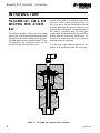
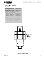
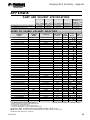
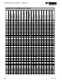
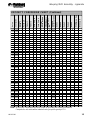
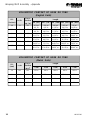
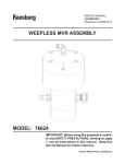
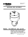
SERVICE MANUAL
LN-9112-00
WEEPING MVR ASSEMBLY
MODEL: TR-SSMM-147, 148, and 225
IMPORTANT: Before using this equipment,
carefully read SAFETY PRECAUTIONS,
starting on page 1, and all instructions in this
manual. Keep this Service Manual for future
reference.
Service Manual Price: $20.00
LN-9112-00
Weeping MVR Assembly - Contents
CONTENTS
SAFETY:
PAGE
1-3
SAFETY PRECAUTIONS............................................................................................................ 1
HAZARDS / SAFEGUARDS........................................................................................................ 2-3
INTRODUCTION:
4-5
TR-SSMM-147, 148 & 225 WEEPING MVR ASSEMBLY........................................................... 4
SPECIFICATIONS....................................................................................................................... 5
MAINTENANCE:
6-9
POSSIBLE CAUSES OF MVR PROBLEMS.............................................................................. 6
PREVENTIVE MAINTENANCE................................................................................................... 6
GENERAL..................................................................................................................................... 6
PRELIMINARY PROCEDURES.................................................................................................. 6-7
DISASSEMBLY PROCEDURES................................................................................................. 7
VALVE BODY SERVICING......................................................................................................... 7
ASSEMBLY PROCEDURES....................................................................................................... 7
TR-SSMM-147, 148 & 225 MVR ASSEMBLY............................................................................. 7-8
FLUID NEEDLE REPLACEMENT............................................................................................... 9
PARTS IDENTIFICATION:
10-11
WEEPING MVR ASSEMBLY / PARTS LIST.............................................................................. 10-11
RECOMMENDED SPARE PARTS............................................................................................. 11
WARRANTY POLICIES:
12
LIMITED WARRANTY.................................................................................................................. 12
APPENDIX:
13-16
PAINT AND SOLVENT SPECIFICATIONS................................................................................ 13
VISCOSITY CONVERSION CHART.......................................................................................... 14
VOLUMETRIC CONTENT OF HOSE OR TUBE....................................................................... 15-16
LN-9112-00
LN-9112-00
Weeping MVR Assembly - Safety
SAFETY
SAFETY PRECAUTIONS
Before operating, maintaining or servicing any
ITW Ransburg coating system, read and
understand all of the technical and safety literature
for your Ransburg products. This manual contains
information that is important for you to know and
understand. This information relates to USER
SAFETY and PREVENTING EQUIPMENT
PROBLEMS. To help you recognize this
information, we use the following symbols. Please
pay particular attention to these sections.
A WARNING! states information to alert you to a
situation that might cause serious injury if
instructions are not followed.
A CAUTION! states information that tells how to
prevent damage to equipment or how to avoid a
situation that might cause minor injury.
!
The user MUST read and be familiar
with the Safety Section in this manual and
the ITW Ransburg safety literature therein
identified.
>
> This manual MUST be read and thor-
oughly understood by ALL personnel who
operate, clean or maintain this equipment!
Special care should be taken to ensure
that the WARNINGS and safety requirements for operating and servicing the
equipment are followed. The user should
be aware of and adhere to ALL local
building and fire codes and ordinances as
well as NFPA 33 SAFETY STANDARD, 1995 EDITION, prior to installing, operating, and/or servicing this
equipment.
A NOTE is information relevant to the procedure in
progress.
While this manual lists standard specifications
and service procedures, some minor deviations
may be found between this literature and your
equipment. Differences in local codes and plant
requirements, material delivery requirements, etc.,
make such variations inevitable. Compare this
manual with your system installation drawings
and appropriate ITW Ransburg equipment manuals
to reconcile such differences.
WARNING
!
WARNING
> The hazards shown on the following
page may occur during the normal use of
this equipment. Please read the hazard
chart beginning on page 2.
Careful study and continued use of this manual will
provide a better understanding of the equipment
and process, resulting in more efficient operation,
longer trouble-free service and faster, easier
troubleshooting. If you do not have the manuals
and safety literature for your ITW Ransburg system,
contact your local ITW Ransburg representative
or ITW Ransburg.
LN-9112-00
1
Weeping MVR Assembly - Safety
AREA
HAZARD
SAFEGUARDS
Tells where
Tells what the hazard is.
Tells how to avoid the hazard.
Fire Hazard
Fire extinguishing equipment must be present in the
spray area and tested periodically.
hazards may occur.
Spray Area
Improper or inadequate operation and maintenance procedures Spray areas must be kept clean to prevent the
will cause a fire hazard.
accumulation of combustible residues.
Smoking must never be allowed in the spray area.
When using solvents for cleaning:
Those used for equipment flushing should have flash
points equal to or higher than those of the coating
material.
Those used for general cleaning must have flash
points above 100oF (37.8oC).
Spray booth ventilation must be kept at the rates
required by NFPA 33, 1995 Edition, OSHA and local
codes. In addition, ventilation must be maintained
during cleaning operations using flammable or
combustible solvents.
Test only in areas free of combustible material.
Non-factory replacement parts or unauthorized
equipment modifications may cause fire or injury.
If used, the key switch bypass is intended for use
only during setup operations. Production should
never be done with safety interlocks disabled.
Never use equipment intended for use in waterborne
installations to spray solvent based materials.
General Use and
Maintenance
Improper operation or maintenance may create a hazard.
Personnel must be properly
trained in the use of this equipment.
Personnel must be given training in accordance with
the requirements of NFPA-33, Chapter 16, 1995
edition.
Instructions and safety precautions must be read and
understood prior to using this equipment.
Comply with appropriate local, state, and national
codes governing ventilation, fire protection, operation
maintenance, and housekeeping. OSHA references
are Sections 1910.94 and 1910.107. Also refer to
NFPA-33, 1995 edition and your insurance company
requirements.
2
LN-9112-00
Weeping MVR Assembly - Safety
AREA
HAZARD
SAFEGUARDS
Tells where
Tells what the hazard is.
Tells how to avoid the hazard.
hazards may occur.
Explosion Hazard / Halogenated hydrocarbon solvents Aluminum is widely used in other spray application
for example: methylene chloride equipment - such as material pumps, regulators,
Incompatible
and 1,1,1,-Trichloroethane are not triggering valves, etc. Halogenated hydrocarbon
Materials
Toxic Substances
chemically compatible with the
aluminum that might be used in
many system components. The
chemical reaction caused by these
solvents reacting with aluminum
can become violent and lead to an
equipment explosion.
solvents must never be used with aluminum equipment
during spraying, flushing, or cleaning. Read the label
or data sheet for the material you intend to spray. If
in doubt as to whether or not a coating or cleaning
material is compatible, contact your material supplier.
Any other type of solvent may be used with aluminum
equipment.
Certain material may be harmful
if inhaled, or if there is contact
with the skin.
Follow the requirements of the Material Safety Data
Sheet supplied by coating material manufacturer.
Adequate exhaust must be provided to keep the air
free of accumulations of toxic materials.
Use a mask or respirator whenever there is a chance
of inhaling sprayed materials. The mask must be
compatible with the material being sprayed and its
concentration. Equipment must be as prescribed by
an industrial hygienist or safety expert, and be NIOSH
approved.
LN-9112-00
3
Weeping MVR Assembly - Introduction
INTRODUCTION
TR-SSMM-147, 148 & 225
WEEPING MVR ASSEMBLY
The material regulator valve is an air-operated
sliding valve. It has a tapered needle and specially
designed fluid ports that permit precise regulation
and rapid response to air command signals. These
characteristics are maintained over the full
operating range of the regulator valve.
Figure 1:
4
Control of the MVR is achieved through an air
pressure control signal generated from the
transducer panel. Air pressure against a solvent
resistant diaphragm moves the needle up and
down across the fluid ports. The tapered seat on
the needle, combined with the fluid port
configuration, allows fluid flow through the MVR to
directly reflect the air pressure control signal. An
increase in air pressure results in an increase in
fluid flow through the regulator.
The flow rate of the material depends on the
position of the shaft taper within the valve body.
TR-SSMM-147 Weeping MVR Assembly
LN-9112-00
Weeping MVR Assembly - Introduction
SPECIFICATIONS
Technical
Maximum Air Pressure:
100 psig (6.9 bar)
Maximum fluid Pressure:
300 psig (207 bar)
Flow Rate: (Dependent upon material
viscosity and needle used.)
#2 Needle Low Flow
(TR-SSMM-149)
#3 Needle Medium Flow (TR-SSMM-150)
#4 Needle High Flow
(TR-SSMM-226)
Ports:
Top and Side Air Ports:
Fluid Inlet & Oulet Ports:
Bottom Weep Port:
Mounting Holes:
1/8-27 NPT (F)
3/8 BSP Threads
3/8-18 NPT (F)
5/16-18
Figure 2:
LN-9112-00
Mounting Footprint
5
Weeping MVR Assembly - Maintenance
MAINTENANCE
POSSIBLE CAUSES OF
MVR PROBLEMS
1. Most problems with the material regulator are
caused by improperly filtered fluid. Particulates
and residue in the material regulator can cause
plugging of the fluid ports and sluggish valve
operation. If repeated disassembly and cleaning
for removal of solids and residue occurs, inspect
the entire fluid supply system. A 100 mesh filter is
recomended for proper filtration.
2. Fluid backup, i.e. reverse flow, can cause
reacted/catalyzed material to enter the material
regulator. Reverse flow will be detected by the
2-K and the system will shut down, however, the
material regulator should be cleaned or flushed
immediately to prevent the fluid from setting-up.
If repeated cleaning is required, inspect the check
valves and adjust the REV FLOW parameter
accordingly.
3. Kinks or tight bends in the control air line may
restrict air flow to the material regulator. Inspect
the condition of exposed tubing periodically and
check the fitting connection at the material regulator.
4. Check the leakage weep port for any signs of
coagulated material. Excessive buildup will cause
the valve to operate improperly. Buildup can also
indicate that the valve needle and valve body
should be replaced.
PREVENTIVE
MAINTENANCE
6
Weekly
Flush the coating material from the system.
2500 Hours of Operation
Rebuild the valve:
1. Inspect the fluid section and fluid needle.
Replace both if excessive leakage is evident.
2. Replace the air diaphragms.
3. Replace the compression spring.
4. Replace the seal SSG-8125 Teflon o-ring.
GENERAL
1. Work from a clean, dry bench.
2. Always install new o-rings, gaskets and diaphragms when the material regulator is
reassembled.
3. Use only lint-free wipers/cloths for cleaning.
4. Refer to the model number of the material
regulator when ordering replacement parts.
PRELIMINARY
PROCEDURES
Prior to removing the material regulator for service or repair, perform the following:
Daily
1. Flush the material regulator with the system
purge.
1. Check the leakage weep ports for fluid leakage.
If fluid leakage is evident, repair at earliest
opportunity.
2. Remove all pressure from the affected fluid
line.
2. Inspect the exposed fluid and air tubing for
kinks, tight bends, leaks, etc.
3. Close the shut-off valves on either side of
the material regulator.
LN-9112-00
Weeping MVR Assembly - Maintenance
4. Clean the exterior of the material regulator
before loosening any fittings.
5. Disconnect the control air line from the material regulator. Cover the exposed hose end to
prevent contamination.
6. Remove the material regulator from the fluid
line.
7. If the fluid lines will be left open during the repair, cover them to prevent contaminants from
entering the fluid system.
DISASSEMBLY
PROCEDURES
Material Regulator Disassembly
1. Clamp the regulator in a bench vise with padded
jaws.
2. Loosen the top (4) housing bolts [4] equally and
alternately.
3. Lift off the upper housing and remove the
diaphragm and needle assembly.
Fluid Section Disassembly
Procedures
1. Loosen the bottom (4) housing bolts [16] to
remove the TR-SHC-149, fluid housing.
VALVE BODY SERVICING
Remove the fittings/adapters from the inlet and
outlet ports of the valve and clean out any coating buildup.
ASSEMBLY PROCEDURES
Needle Preassembly
1. Assemble the TR-SSF-506 small washer [10],
onto the TR-SSF-031 screw [9]. The radius side
of the washer should be facing away from the
screw head.
2. Now assemble the (3) TR-SSMM-151 diaphragms [8], onto the TR-SSF-031 cap screw [9],
and then place the TR-SSF-505 large washer, on
top of the diaphragms.
NOTE
NOTE
> As the bolts are loosened the load
spring will force the housing halves apart.
Keep equal tension on the housing bolts to
avoid damaging the internal components.
Diaphragm Removal
1. Remove the allen screw from the diaphragm
end of the needle assembly and lift off the flat
washer.
2. Remove the diaphragm flat washers and
regulator spring. The diaphragm is constructed of
(3) layers of Teflon material. It should be replaced
if fluid has leaked into the air pressure chamber or
the diaphragm shows signs of wear.
LN-9112-00
> It is highly recomended that the diaphragm
[7] be replaced each time the housing is
opened or unit is rebuilt.
3. Apply a small drop of 7969-031, loctite (blue),
onto the cap screw and assemble onto the TRSSMM-XXX, needle. Tighten the needle using the
appropriate Allen wrenches. For exact assembly
detail, see Figure 4.
TR-SSMM-147, 148, and 225
MVR ASSEMBLY
Assemble Bolt in Housing
Locate TR-SSHC-149 housing and TR-SSF-508
bolt; assemble bolt loosely into body with nose of
bolt slightly inside of diameter to provide needed
alignment of bushing when being pressed into
place.
7
Weeping MVR Assembly - Maintenance
Press Bushing Into
Previously Removed)
Body
(If
Assemble Needle Assembly Into
the Piston and Fluid Housing
Locate item TR-SSHC-149 housing with bolt
assembled into it and apply petroleum jelly to the
inside diameter of bushing sparingly. Place the
housing onto the arbor, press with the longest
"neck" side down on the table.
Locate TR-SSF-504 Support washer and place
into lower housing as shown in Figure 4. Next
place the A10231-00 spring into lower housing as
shown in Figure 4.
Now locate TR-SSHC-153 bushing and sparingly
apply Vaseline to the outside diameter of the
bushing. Carefully align the bushing into the
housing with one of the slot sides of the bushing
aligned with the bolt inside the housing.
NOTE
> The "screwdriver" slot in the bushing
should be facing downwards during the
press operation.
Now carefully bring down the arbor press tongue
onto the bushing and press it into place slowly and
steady, do not stop. Make sure to keep a steady
press motion during the press operation to assure
bushing does not gull the body during the press
operation. Press the bushing in until it is flush with
the top of the housing.
Apply petroleum jelly onto the outside diameter of
needle assembly sparingly. Now align needle
assembly into bushing and carefully slide needle
into the bushing until the lower diaphragm support
rests onto the top of the spring.
Assemble Upper Housing
Pull TR-SSHC-151 upper housing onto the lower
piston assembly. Once the upper housing is
oriented to its correct position, locate four screws
TR-SSF-100 and assemble into the counter bore
of the upper housing. Carefully take down the
screws evely using an "X" pattern to avoid stripping
out the threaded holes in the lower housing, tighten
securely.
Assemble Fluid Housing Onto
Lower Piston Housing
Locate fluid housing assembly with pressed in
bushing and insert SSF-8125 [15] Teflon o-ring
into the counter bore of bushing as shown in
Figure 4. Once installed, lubricate Teflon o-ring
with petroleum jelly.
Turn TR-SSHC-150 lower housing upside down
on the table with threaded holes facing up. Take
TR-SSHC-149 fluid housing and assemble it into
the lower housing. Now rotate the housing until the
TR-SSF-508 bolt is 90 degrees away from the
mounting hole in TR-SSHC-150 lower housing.
Pull TR-SSF-509 SHCS screw and apple (blue)
loctite 7969-03 onto the four screws. Proceed to
assemble the screws into the fluid housing and
lower housing. Tighten the screws securely.
8
LN-9112-00
Weeping MVR Assembly - Maintenance
FLUID NEEDLE REPLACEMENT
NOTE
> When replacing MVR fluid needles,
use Figure 3 below to determine the correct size and part number. The number of
grooves at the top of the needle correlates
to the dash number of the part number.
TR-SSMM-149 / Low Flow Fluid Needle
TR-SSMM-150 / Medium Flow Fluid Needle
TR-SSMM-226 / High Flow Fluid Needle
Figure 3:
LN-9112-00
Weeping MVR Fluid Needles
9
Weeping MVR Assembly - Parts Identification
PARTS IDENTIFICATION
16
13
12
15
17
14
9
3
11
7
10
4
6
1
8
5
2
Figure 4:
10
Weeping MVR Assembly
LN-9112-00
Weeping MVR Assembly - Parts Identification
WEEPING MVR ASSEMBLY - PARTS LIST
Item #
1
2
3
4
5
6
7
8
9
10
11
12
13
14
15
16
17
Part #
(Figure 4)
Description
TR-SSHC-149
TR-SSF-509
TR-SSHC-153
TR-SSF-508
TR-SSF-504
78783-00
TR-SSMM-151
TR-SSF-505
See Table "A"
TR-SSF-506
TR-SSF-031
TR-SSF-100
SSP-6427
41-FP-1006
SSG-8125
A10509-00
TR-SSHC-150
A10508-00
TR-SSHC-151
Fluid Housing
Screw, Socket Head Cap, M6 X 75
Bushing
Bolt
Support Washer
Spring
Air Diaphragm
Lower Diameter Support
Needle
Upper Diaphragm, Support
Screw, Socket Head Cap, M4 X 20
Screw, Socket Head Cap, M8 X 40
Fitting, Elbow, 1/8 NPT X 5/32 ODT
Plug
O-Ring, Teflon
Lower Housing (After 12/03)
Lower Housing (Prior to 12/03)
Upper Housing (After 12/03)
Upper Housing (Prior to 12/03)
Qty
1
4
1
1
1
1
3
1
1
1
1
4
1
1
1
1
1
1
1
3
4
2
PARTS LIST BULLET DEFINITION TABLE
4
Apply thread sealant 7969-10.
3
Apply blue loctite 7969-03.
2
Apply petroleum jelly on o-rings before installation.
* All dimensions are in millimeters. unless otherwise specified.
TABLE "A"
MVR Assy.
Description
Needle Part #
TR-SSMM-147
TR-SSMM-148
TR-SSMM-225
#2 Needle
#3 Needle
#4 Needle
TR-SSMM-149
TR-SSMM-150
TR-SSMM-226
RECOMMENDED SPARE PARTS
Part #
TR-SSMM-151
78783-00
SSG-8125
LN-9112-00
Description
Air Diaphragm, MVR Assembly
Compression Spring, MVR
O-Ring, Teflon
Qty
3
1
1
11
Weeping MVR Assembly - Warranty Policies
WARRANTY POLICIES
LIMITED WARRANTY
ITW Ransburg will replace or repair without charge
any part and/or equipment that falls within the
specified time (see below) because of faulty
workmanship or material, provided that the
equipment has been used and maintained in
accordance with ITW Ransburg's written safety
and operating instructions, and has been used
under normal operating conditions. Normal wear
items are excluded.
THE USE OF OTHER THAN RANSBURG
APPROVED PARTS, VOIDS ALL WARRANTIES.
SPARE PARTS: One hundred and eighty (180)
days from date of purchase, except for rebuilt
parts (any part number ending in "R") for which the
warranty period is ninety (90) days.
EQUIPMENT: When purchased as a complete
unit, (i.e., guns, power supplies, control units,
etc.), is one (1) year from date of purchase.
WRAPPING THE APPLICATOR IN PLASTIC,
SHRINK-WRAP, ETC., WILL VOID THIS
WARRANTY.
ITW RANSBURG'S ONLY OBLIGATION
UNDER THIS WARRANTY IS TO REPLACE
PARTS THAT HAVE FAILED BECAUSE OF
FAULTY WORKMANSHIP OR MATERIALS.
THERE ARE NO IMPLIED WARRANTIES NOR
WAR-RANTIES OF EITHER MERCHANTABILITY OR FITNESS FOR A PARTICULAR
PURPOSE. ITW RANSBURG ASSUMES NO
LIABILITY FOR INJURY, DAMAGE TO PROPERTY OR FOR CONSEQUENTIAL DAMAGES
FOR LOSS OF GOODWILL OR PRODUCTION
OR INCOME, WHICH RESULT FROM USE OR
MISUSE OF THE EQUIPMENT BY PURCHASER OR OTHERS.
EXCLUSIONS:
If, in ITW Ransburg's opinion the warranty item in
question, or other items damaged by this part was
improperly installed, operated or maintained, ITW
Ransburg will assume no responsibility for repair
or replacement of the item or items. The purchaser,
therefore will assume all responsibility for any cost
of repair or replacement and service related costs
if applicable.
FLUID HANDLING: One (1) year from date of
purchase (i.e., Totalizer, CCV Valves, etc.).
AIR BEARING ROTATORS: Fifteen thousand
(15,000) hours or three (3) years, whichever occurs
first. Warranty period begins on the date of
purchase.
12
LN-9112-00
Weeping MVR Assembly - Appendix
APPENDIX
PAINT AND SOLVENT SPECIFICATIONS
RECOMMENDED VISCOSITY USING A ZAHN NO. 2
PAINT ELECTRICAL RESISTANCE**
RECOMMENDED DELIVERY (UP TO)
REA TM / EFM T M
18 TO 30 SEC
.1 MΩ TO ∞
1000 cc/min
REM TM / M90 T M NO. 2 HAND GUN TURBODISK T M
18 TO 30 SEC
20 TO 60 SEC
20 TO 60 SEC
.1 MΩ TO ∞
.1 TO 1 MΩ
.1 MΩ TO ∞
1500 cc/min
180 cc/min
1000 cc/min
AEROBELL ® II***
AEROBELL®
AEROBELL ® 33
RMA-101 T M
20 TO 60 SEC
.1 MΩ TO ∞
500 cc/min
GUIDE TO USABLE SOLVENT SELECTION
Chemical
Name
Common
Name
Category
Methylene Chloride Chlorinated Solvents
DICHLOROMETHANE
Aliphatic Hydrocarbons
Naptha
VM & P NAPHTHA
Ketones
ACETONE
Esters
METHYL ACETATE
Aromatic Hydrocarbons
BENZENE
Esters
ETHYL ACETATE
Ketones
MEK
2-BUTANONE
Esters
ISO-PROPYL ACETATE
Alcohols
IPA
ISOPROPYL ALCOHOL
Ketones
MPK
2-PENTANONE
Alcohols
Methyl Alcohol
METHANOL
Esters
n-Propyl Acetate
PROPYL ACETATE
Aromatic Hydrocarbons
Toluene
TOLUOL
Ketones
MIBK
METHYL ISOBUTYL KETONE
Esters
ISOBUTYL ACETATE
Alcohols
Ethyl Alcohol
ETHANOL
Esters
BUTYL ACETATE
Aromatic Hydrocarbons
ETHYLBENZENE
Alcohols
n-Propyl Alcohol
1-PROPANOL
Alcohols
sec.-Butyl Alcohol
2-BUTANOL
Aromatic Hydrocarbons
Xylene
XYLOL
Esters
AMYL ACETATE
Alcohols
2-METHYLPROPANOL
iso-Butyl Alcohol
Esters
METHYL AMYL ACETATE
Ketones
5-METHYL-2-HEXANONE
MIAK
Alcohols
1-BUTANOL
n-Butyl Alcohol
Glycol Ethers
2-ETHOXYETHANOL
Ketones
2-HEPTANONE
MAK
Ketones
CYCLOHEXANONE
Aromatic Hydrocarbons
AROMATIC-100
SC#100
Ketones
DIISOBUTYL KETONE
DIBK
Alcohols
1-PENTANOL
Amyl Alcohol
Ketones
DIACETONE ALCOHOL
Glycol Ethers
2-BUTOXYETHANOL
Butyl Cellosolve
Alcohols
CYCLOHEXANOL
Aromatic Hydrocarbons
SC#150
AROMATIC-150
Aromatic Hydrocarbons
AROMATIC-200
*CAS
Flash Point ††
Number
(TCC)
65oF
-18oF
90oF
12oF
24oF
16oF
35oF
53oF
104oF
50oF
55oF
48oF
60oF
69oF
7 8 oF
64oF
74oF
72oF
79oF
106oF
82oF
96oF
96oF
95oF
164oF
102oF
111oF
111oF
120oF
133oF
154oF
111oF
149oF
203oF
75-09-2
8030-30-6
67-64-1
79-20-9
71-43-2
141-78-6
78-93-3
108-21-4
67-63-0
107-87-9
67-56-1
109-60-4
108-88-3
108-10-1
110-19-0
64-17-5
123-86-4
100-41-4
71-23-8
78-92-2
1330-02-07
628-63-7
78-83-1
108-84-9
110-12-3
71-36-3
110-80-5
110-43-0
108-94-1
108-83-8
71-41-0
123-42-2
111-76-2
108-93-0
Evap.
Rate†
14.5
10
5.6
5.3
5.1
3.9
3.8
3.4
2.5
2.5
2.1
2.1
1.9
1.6
1.5
1.4
1.0
.89
.86
.81
.80
.67
.62
.50
.50
.43
.38
.40
.29
.20
.19
.15
.12
.07
.05
.004
.003
⇑F
A
S
T
E
R
S
L
O
W
E
R
⇓
Elec.
Res.**
HIGH
HIGH
LOW
LOW
HIGH
MEDIUM
MEDIUM
LOW
LOW
MEDIUM
LOW
LOW
HIGH
MEDIUM
LOW
LOW
LOW
HIGH
LOW
LOW
HIGH
MEDIUM
LOW
LOW
MEDIUM
LOW
LOW
MEDIUM
MEDIUM
HIGH
MEDIUM
LOW
LOW
LOW
LOW
HIGH
HIGH
* CAS Number: Chemical Abstract Service Number.
© 2004 Illinois Tool Works Inc. All rights reserved.
** Electrical Resistance using the ITW Ransburg Meter.
*** Solvent Base Configuration Only.
†
Information Obtained From: http://solvdb.ncms.org
††
The lowest temperature at which a volatile fluid will ignite.
Evaporation Rate is Based Upon Butyl Acetate Having a Rate of 1.0
NOTE: Chart provides resistance and control information that we feel is necessary when using
ITW Ransburg/ITW Automotive equipment.
LN-9112-00
13
Weeping MVR Assembly - Appendix
Din Cup 4
Sears
Craftsman Cup
Saybolt
Universal SSU
Gardner Lithographic
Krebs Unit
KU
Gardner Holdt Bubble
Ford Cup 4
Ford Cup 3
30
16
10
80
34
17
11
Zahn 5
60
8 A-3
Zahn 4
5 A-4
25
Zahn 3
20
12
Zahn 2
11
30
Zahn 1
27
15
Fisher 2
DuPont
Parlin 10
10
Fisher 1
DuPont
Parlin 7
.1
.15
Poise
14
Centipoise
VISCOSITY CONVERSION CHART
.2
20
32
13
30
15
12
10
100
37
18
12
.25
25
37
14
35
17
15
12 A-2
130
41
19
13
.3
30
43
15
39
18
19
14 A-1
160
44
20
14
.4
40
50
16
50
21
25
18
.5
50
57
17
24
29
22
.6
60
64
18
29
33
25
.7
70
20
33
36
28
.8
80
22
39
41
31
.9
90
23
44
45
32
1.0
100
25
50
50
34
1.2
120
30
62
58
1.4
140
32
66
1.6
160
1.8
2.0
2.2
210
52
22
19
15
30
260
60
24
20
16
33
320
68
27
21
18
35
370
30
23
21
37
430
34
24
23
38
480
37
10
26
25
D
40
530
41
12
10
27
27
41
E
43
580
49
14
11
31
31
45
F
46
690
58
16
13
34
34
37
50
G
48
790
66
18
14
38
38
180
41
54
50
900
74
20
16
40
43
200
45
58
H
52
1000
82
23
17
10
44
46
220
62
I
54
1100
25
18
11
51
2.4
240
65
J
56
1200
27
20
12
55
2.6
260
68
58
1280
30
21
13
58
2.8
280
70
K
59
1380
32
22
14
63
3.0
300
74
L
60
1475
34
24
15
68
3.2
320
M
1530
36
25
16
72
3.4
340
N
1630
39
26
17
76
3.6
360
O
62
1730
41
28
18
82
3.8
380
1850
43
29
19
86
4.0
400
P
64
1950
46
30
20
90
4.2
420
2050
48
32
21
95
4.4
440
Q
4.6
460
R
4.8
480
5.0
500
5.5
6.0
7.0
700
8.0
800
9.0
900
V
10.0 1000
W
A
B
C
000
2160
50
33
22
100
66
2270
52
34
23
104
67
2380
54
36
24
109
S
68
2480
57
37
25
112
550
T
69
2660
63
40
27
124
600
U
71
2900
68
44
30
135
74
3375
51
35
160
77
3380
58
40
172
81
4300
64
45
195
85
4600
49
218
11.0 1100
88
5200
55
12.0 1200
92
5620
59
00
0
LN-9112-00
Weeping MVR Assembly - Appendix
21.0
2100
9850
22.0
2200
10300
23.0
2300
24.0
2400
25.0
2500
30.0
3000
35.0
3500
40.0
4000
45.0
4500
50.0
5000
55.0
5500
60.0
6000
65.0
6500
30000
70.0
7000
32500
75.0
7500
35000
80.0
8000
37000
85.0
8500
39500
90.0
9000
41000
95.0
9500
100.0 10000
64
8500
9000
103
Z
2
9400
105 10750
109 11200
Z-1
114 11600
121 14500
Z-2
3
129 16500
133 18500
Z-3
136 21000
23500
26000
Z-4
4
2800
43000
Z-5
5
46500
110.0 11000
51000
120.0 12000
55005
130.0 13000
60000
140.0 14000
65000
150.0 15000
Din Cup 4
2000
Sears
Craftsman Cup
20.0
Y
Zahn 5
1900
Zahn 4
1800
19.0
Zahn 3
18.0
1
Zahn 2
8000
X
Zahn 1
Saybolt
Universal SSU
101
Gardner Holdt Bubble
1700
Ford Cup 4
7500
17.0
16.0
Ford Cup 3
7000
100
15.0
Fisher 2
98
1600
1400
Fisher 1
1500
1300
14.0
DuPont
Parlin 10
6480
13.0
DuPont
Parlin 7
6100
96
Centipoise
95
Poise
Gardner Lithographic
Krebs Unit
KU
VISCOSITY CONVERSION CHART (Continued)
Z-6
67500
160.0 16000
74000
170.0 17000
83500
180.0 18000
83500
190.0 19000
88000
200.0 20000
93000
300.0 30000
140000
Note: All viscosity comparisons are as accurate as possible with existing information.
Comparisons are made with a material having a specific gravity of 1.0.
LN-9112-00
15
Weeping MVR Assembly - Appendix
VOLUMETRIC CONTENT OF HOSE OR TUBE
(English Units)
Cross
Section
(sq. in.)
I.D.
(inches)
cc/ft.
1/8
2.4
.012
3/16
5.4
.027
1/4
9.6
.049
5/16
13.8
.070
3/8
43.8
.110
1/2
78.04
.196
Length
5ft. (60") 10ft. (120") 15ft. (180") 25ft. (300") 50ft. (600")
.003 gal.
.4 fl. oz.
.007 gal.
.9 fl. oz.
.012 gal.
1.6 fl. oz.
.018 gal.
2.3 fl. oz.
.028 gal.
3.65 fl. oz.
.052 gal.
6.5 fl. oz.
.005 gal.
.8 fl. oz.
.014 gal.
1.8 fl. oz.
.024 gal.
3.2 fl. oz.
.036 gal.
4.6 fl. oz.
.056 gal.
7.3 fl. oz.
.104 gal.
13.0 fl. oz.
.009 gal.
1.2 fl. oz.
.021 gal.
2.7 fl. oz.
.035 gal.
4.8 fl. oz.
.054 gal.
6.9 fl. oz.
.084 gal.
10.95 fl. oz.
.156 gal.
19.5 fl. oz.
.015 gal.
2.0 fl. oz.
.035 gal.
4.5 fl. oz.
.050 gal.
8.0 fl. oz.
.090 gal.
11.5 fl. oz.
.140 gal.
18.25 fl. oz.
.260 gal.
32.5 fl. oz.
.03 gal.
4.0 fl. oz.
.07 gal.
9.0 fl. oz.
.125 gal.
16.0 fl. oz.
.180 gal.
23.0 fl. oz.
.250 gal.
36.5 fl. oz.
.520 gal.
65.0 fl. oz.
VOLUMETRIC CONTENT OF HOSE OR TUBE
(Metric Units)
16
Cross
Section
(m m 2 )
1.5m
3.0m
4.5m
6.0m
7.5m
102
10.2
153 cc
306 cc
459 cc
612 cc
765 cc
5.6
246
24.6
369 cc
738 cc
1.1 Liters
1.5 Liters
1.8 Liters
6.8
363
36.3
544 cc
1.1 Liters
1.6 Liters
2.2 Liters
2.7 Liters
8.8
608
60.8
912 cc
1.8 Liters
2.7 Liters
3.6 Liters
4.6 Liters
I.D.
(mm)
cc/m
3.6
Length
LN-9112-00
Weeping MVR Assembly - Appendix
LN-9112-00
Service Manual Price: $20.00
Manufacturing
1910 North Wayne Street
Angola, Indiana 46703-9100
Telephone: 260/665-8800
Fax: 260/665-8516
Technical/Service Assistance
Automotive Assembly and Tier I
Industrial Systems
Ransburg Guns
Telephone: 800/ 626-3565 Fax: 419/ 470-2040
Telephone: 800/ 233-3366 Fax: 419/ 470-2071
Telephone: 800/ 233-3366 Fax: 419/ 470-2071
Technical Support Representative will direct you to the appropriate telephone
number for ordering Spare Parts.
© 2004 Illinois Tool Works Inc. All rights reserved.
Models and specifications subject to change without notice.
Form No. LN-9112-00
Litho in U.S.A.
02/04 -50