1
DS-1200 G3 Service Manual
Page 3-21
Issue 1 Sep 2013
3.4 FOLDER MAINTENANCE
Fold roller replacement
The folder module consists of five fold rollers and three fold plates, allowing all combinations of folds. Fold plates 1 & 3 are vertical mounted
above the rollers; fold plate 2 is below, pointing downwards. A springloaded blanking beam is fitted to the roller at the opening of each fold
plate, this being automatically operated when required by a pusher on
the backstop of the fold plate. The fold plates are motor driven and no
manual settings are required. The two lower fold rollers are spring-loaded, the tension of which can be adjusted.
The folder is a complex structure with the roller shaft locked to the
bearings with adhesive. Further positive locking is provided by 2 ring
nuts on the ends of each shaft, these also being locked in place by adhesive. It is designed for considerable longevity and fold roller should
not normally need replacement. However, if they do, or they become
damaged, it is not considered feasible to strip the assembly and it must
be replaced as a whole. Folder module A0286A is available as a spares
assembly which comprises the core folder assembly. It does not include: fold plates, outer side plates & posts, pulleys, belts, circuit board,
drive motor, fold plate motors, microswitch.
Roller spring adjustment
The folder springs on the two lower rollers are adjustable by means of
eccentric spring posts. The springs are factory set to maximum tension
which should suit the great majority of applications, but if lightweight
forms are being processed (min. 70 gsm), rippling of the form will be
prevented by reducing spring tension, as described below.
1.
Unlatch fold plates 1/3 and hinge forward.
2.
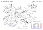
Slacken the screws behind the adjustable spring posts (see Fig. 22
below) and turn the posts to reduce spring tension. Each post on
each side must be turned by a similar amount. Ensure the screws
are fully re-tightened.
3.
Test run the machine to determine improvement and adjust further
if required - the springs should be as tight as possible while maintaining a smoothly folded form
Spring posts
1.
Remove the folder as described in section 3.3.2.
2.
Remove the outer side plates, posts and stretcher bars. Note: one
of the posts requires removal of the PCB chassis - see step 5.
3.
Remove fold plate 2 by taking out the 4 screws behind (leaving the
blocks in place). From the inside, remove the 2 screws securing
the fold plate motor; lift this out and disconnect the cable (see Fig.
23 below) . Also remove the angled chassis plate behind the fold
plate.
Fold plate motor
screws
Fold plate
mounting block
Fig. 23
4.
Tilt fold plates 1/3 forward and remove the fold plate motors
from inside the chassis, as with fold plate 2. Take out the screw at each
end of the pivot shaft and lift out the fold plate assembly.
Fig. 22
Page 3-21