1
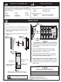
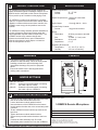
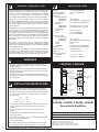
INSTALLATION
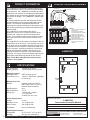
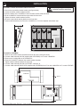
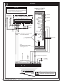
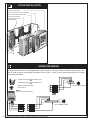
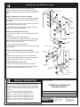
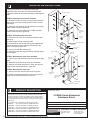
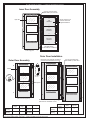
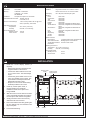
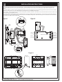
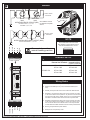
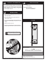
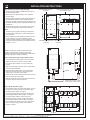
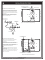
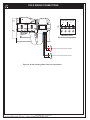
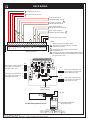
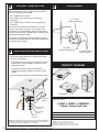
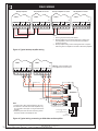
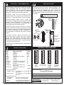
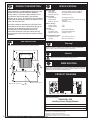
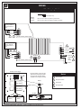
Mount the Rail Expansion card on the studs at the right side of the chassis. Connect the power and data cables from the Rail Expansion card to the
previous and next chassis.
3.
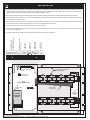
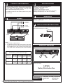
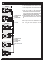
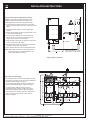
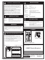
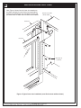
Mount the 3-FTCU telephone controller on the six spacers on the right side of the chassis as shown in the figure below. Run ribbon cable (P/N 25019500) from connector J2 on the 3-FTCU controller board to connector J1 on the Rail Expansion card.
4.
Mount the 3-ASU controller board on the six spacers on the left side of the chassis as shown below. Run ribbon cable (P/N 250195-00) from connector
J2 on the 3-ASU controller board to connector J1 on the 3-FTCU telephone controller board.
5.
Install the 3-ASUMX Expansion Memory board, if used, in connector J4 of the 3-ASU controller board.
6.
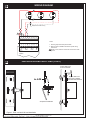
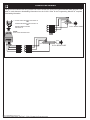
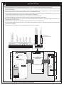
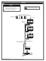
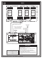
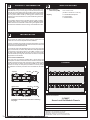
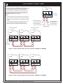
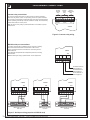
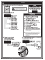
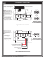
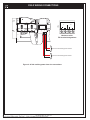
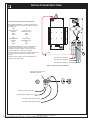
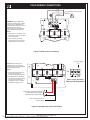
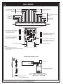
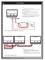
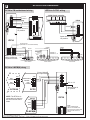
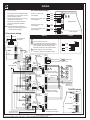
Terminate the field wiring on TB1 of the 3-ASU and TB1 of the 3-FTCU. Refer to the Wiring section on the next page.
7.
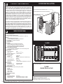
Run ribbon cable (P/N 250194-00) from connector J3 on the 3-FTCU controller board to connector J2 on the 3-FTCU display board mounted in the
telephone control unit cover assembly.
8.
Install the 3-FTCU cover assembly over the telephone controller board and secure it with 4 nuts and washers.
9.
Run ribbon cable (P/N 250194-00) from connector J3 on the3-ASU controller board to connector J1 on the 3-ASU control board mounted in the Audio
Source Unit cover assembly.
10.
Install the 3-ASU cover assembly over the controller board and secure with 4 nuts and washers.
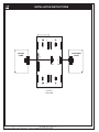
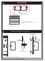
REMOTE ASUs ONLY
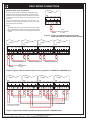
FROM 3-FTCU
AUDIO DATA
PRIMARY SECONDARY
TO REMOTE
AUDIO SOURCE UNIT
MUST BE WITHIN
20 FEET AND IN CONDUIT
1 2 3 4
9 10
REMOTE ASU
INTERFACE
COMMON
PHONE RISER
CLASS A PHONE
RISER RETURN
AUXILIARY
AUDIO INPUT
LOW LEVEL
PAGE OUT
+-
REMOTE MIC
PAGE
OUT
TELEPHONE
REMOTE MIC
AUDIO INPUT
+ -+ REMOTE MIC
PTT KEY
NETWORK AUDIO RISER
TO TB2 AUDIO A IN on
3-CPU PANEL CONTROLLER
TELEPHONE RISER
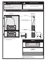
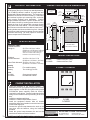
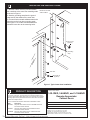
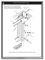
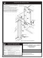
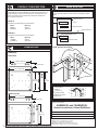
Mount the chassis assembly on the six #6-32 studs at rear of cabinet. Secure the chassis to cabinet with washers and nuts provided.
2.
CLASS A TELEPHONE
RISER RETURN
1.
KEY
AUDIO
AUX
1
2
3
4
5
6
7
8
9
10
14
1
AUDIO DATA
PRIMARY SECONDARY
1
TELEPHONE
PAGE
OUT
REMOTE MIC
KEY
TB1
AUDIO
AUX
RX TX
14
TB1
TX RX
J1
J2
Auxiliary Input
Gain Adjust
J5
J2
3-ASU
AUDIO SOURCE UNIT
Write protect
switch
J1
3-FTCU
FIRFIGHTER'S TELEPHONE
CONTROL UNIT
J2
J3
Ribbon cable
P/N 250195-00
To 3-ASU display
J3
3-ASUMX
EXPANSION
MEMORY
J4
J6
DIN
J7
BOUT
J1
RAIL
CHASSIS
INTERFACE
CARD
COUT
DOUT
J8
J9
To 3-FTCU display
J4
[3ASUPC.CDR]
P/N: 270481 REV: 2.0 Page 2 of 4
J3
CIN
AIN
AOUT
BIN
TR RX TX
Technical Manuals Online! - http://www.tech-man.com