1
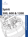
LIBERATOR
G4
SERVICE
SERVICE MANUAL
MANUAL
Preface
I
SERVICE MANUAL
LIBERATOR SERIES—G4
LIB20, LIB30, LIB37, LIB45, LIB60
CAIRE, Inc.
1800 Sandy Plains Industrial Parkway
Suite 316
Marietta, GA 30066-6363
www.cairemedical.com
Customer/Technical Service:
United States
Phone:
800 482 2473
Fax :
Asia, Australia, Pacific Rim
Phone:
+61 297 494333 Fax:
Europe
Phone:
+44 1344 403100 Fax:
Abbreviations
FCV Flow Control Valve
LED Light Emitting Diode
LOX Liquid Oxygen
LPM Liters Per Minute
NER Normal Evaporation Rate
POI Patient Operating Instructions
N2 Nitrogen Gas
TF Top Fill
DF Dual Fill
888 932 2473
888 932 2473
888 932 2473
PRV
QDV
RMA
RP
RR
SRV
O2
SF
PTFE
Primary Relief Valve
Quick Disconnect Valve
Return Materials Authorization
Repair Procedure
Removal and Replacement
Secondary Relief Valve
Oxygen Gas
Side Fill
Polytetrafluoroethylene (“Teflon”)
Definition of Terms
WARNING Description of a condition that can result in personal injury or death.
CAUTION Description of a condition that can result in equipment or component damage.
NOTE
A statement containing information important enough to emphasize or repeat.
(ITEM)
Item numbers used throughout this manual are shown on the illustrations beginning on page 34.
Disclaimer
This manual is intended for use by experienced personnel only. No attempt should be made to fill or maintain this equipment
until both this manual and the Patient Operating Instruction booklet have been read and fully understood.
PN 10662649 Rev L
-1-
Table of Contents II
I. Preface . . . . . . . . . . . . . . . . . . . . . . . . . . . . . . . . . .1
II. Table of Contents . . . . . . . . . . . . . . . . . . . . . . . . . .3
III. Equipment Description . . . . . . . . . . . . . . . . . . . . . .4
IV. Specifications . . . . . . . . . . . . . . . . . . . . . . . . . . . . .5
V. Safety . . . . . . . . . . . . . . . . . . . . . . . . . . . . . . . . . . .6
VI. Theory of Operation . . . . . . . . . . . . . . . . . . . . . . . .7
VII. Unpacking and Setup . . . . . . . . . . . . . . . . . . . . . .10
VIII. Operation . . . . . . . . . . . . . . . . . . . . . . . . . . . . . . .11
IX. Routine Maintenance . . . . . . . . . . . . . . . . . . . . . .13
X. Troubleshooting (Table of Contents) . . . . . . . . . . .15
Troubleshooting Chart . . . . . . . . . . . . . . . . . . . . .16
Repair Procedures . . . . . . . . . . . . . . . . . . . . . . . .18
Service Tools/Equipment/Supplies . . . . . . . . . . . .31
XI. Parts Price List . . . . . . . . . . . . . . . . . . . . . . . . . . .32
Ordering Information . . . . . . . . . . . . . . . . . . . . . . .33
XII. Restocking Policy . . . . . . . . . . . . . . . . . . . . . . . . .34
XIII. Notes . . . . . . . . . . . . . . . . . . . . . . . . . . . . . . . . . .35
PN 10662649 Rev L
-3-
III Equipment Description
FIGURE 1: Liberator Components
The CAIRE Liberator® is the stationary component of the
Liberator/Portable supplementary oxygen system. The Liberator
incorporates a stainless steel cryogenic container with the valves,
plumbing, and associated hardware required to deliver gaseous
oxygen to the patient at near ambient temperature.
The Liberator is comprised of four major assemblies,
grouped according to function.
1. Cryogenic Container – This assembly is a double walled,
vacuum insulated dewar for storing liquid oxygen (LOX)
at approximately -180°C (-300° F). The inner vessel is
designed to safely hold liquid oxygen and is protected from
over pressurization by the primary relief valve. Vacuum
insulation between the inner and outer vessel keeps outside
heat from causing the cold liquid inside to evaporate.
2. Breathing Circuit – This circuit consists of the manifold
assembly, fixed orifice rotary flow control valve (FCV),
breathing coil, and warming coil. It withdraws liquid
oxygen from the cryogenic container, warms it to near
ambient temperature, and regulates the flow of oxygen gas
to the patient. Any water that condenses on the cold coils is
routed into the condensate bottle. An economizer regulator
is utilized to conserve LOX by drawing oxygen head gas
into the breathing circuit.
3. Shroud Assembly – The shroud assembly houses and
protects the breathing circuit and liquid level meter. Labels
listing safety information and patient operating instructions
are affixed to the side of the shroud.
4. Liquid Level Meter – This system uses a capacitance
probe and an electronic (LED) readout to measure and
display the LOX level by pressing the onboard operate
button.
An optional roller base can be provided to help move the
Liberator.
* For Top Fill or Dual Models Only
-4-
PN 10662649 Rev L
Specifications (Nominal Values) IV
LIBERATOR 20
LIBERATOR 30
Liberator 37
24,6 (52)
21,6
17 780
34,0 (75)
31,2
25 650
41,7 (92)
38,3
31 460
Capacity
kg (lbs) LOX
Liquid Liters
Gaseous Liters
LIBERATOR 45 LIBERATOR 60
50,8 (112)
46,6
38 300
65,3(144)
60,0
49 200
Selectable Flow Rates
Liters Per Minute (LPM):
Off 0,25 0,50 0,75 1,0 1,5 2,0 2,5 3,0 4,0 5,0 6,0 8,0 10 12 15
Flow Rate Accuracy
± 0,1 liter per minute or ±10% of flow setting, whichever is greater
Hours of Operation
@ 2 LPM
148
213
262
319
410
Side
Top
Side
Top
Side
Top
Side
Top
Side
Top
Operating Pressure (Economizer Regulator)
Bar (PSIG)
1,4 (20)
1,4 (20)
1,4 (20)
1,4 (20)
1,4 (20)
Primary Relief Valve Setting
Bar (PSIG)
1,6 (23)
1,6 (23)
1,6 (23)
1,6 (23)
1,6 (23)
Secondary Relief Valve Setting
Bar (PSIG)
2,1 (30)
2,1 (30)
2,1 (30)
2,1 (30)
2,1 (30)
0,68 (1.5)
0,68 (1.5)
0,68 (1.5)
0,73 (1.6)
3.0
2.0
3.5
2.5
4.0
3.0
5.5
4.0
Standard Fill Connections
Normal Evaporation Rate
kg (lbs) per day
0,68 (1.5)
Filling Time (Fast Fill Technique)
Warm minutes
2.5
Cold minutes
1.5
Height
cm (in)
62,2 (24.5)
74,9 (29.5)
83,2 (32.75)
94,0 (37)
99,1 (39)
Diameter
cm (in)
35,6 (14)
35,6 (14)
35,6 (14)
35,6 (14)
40,6 (16)
Weight
Empty kg (lbs)
Full kg (lbs)
17,6 (39)
41,3 (91)
20,4 (45)
54,4 (120)
22,7 (50)
64,4 (142)
24,9 (55)
75,7 (167)
29,9 (66)
95,3 (210)
Fill Connector Types
Side Mounted Rotary Coupling
Top Mounted Rotary Coupling
Top Mounted Push Coupling
PN 10662649 Rev L
-5-
V Safety
Oxygen, as it exists at standard atmospheric pressure and
temperature, is a colorless, odorless, and tasteless gas. Oxygen
constitutes 21% of the atmosphere, by volume. Aside from its
well-documented ability to sustain life, oxygen also supports
combustion, even though it is nonflammable. Many substances
which will burn in air, burn at a faster rate and at a higher
temperature in an oxygen enriched atmosphere. Other materials
that do not burn in air will burn as oxygen concentration
increases. Additionally, many greases and liquid solvents
become extremely hazardous materials when placed in an
oxygen-enriched environment. In its liquid form, oxygen is still
odorless and tasteless, but is pale blue in color. At an operating
pressure of 1,4 bar (20 psig), the temperature of liquid oxygen
is about -173°C (-280° F). Skin exposed to such a low
temperature can become severely frostbitten.
These hazards require certain safety precautions to be taken
when working with or around gaseous and/or liquid oxygen:
1. Never permit combustible substances such as greases, oils,
solvents, or other compounds not oxygen compatible to
contact any component of the unit exposed to higher-thanatmospheric concentrations of gaseous or liquid oxygen.
This especially applies to tubing, fittings, and valves.
2. Keep oxygen equipment away from open flames or
electrical appliances such as heaters, stoves, toasters, and
other devices with heating elements.
3. Never permit smoking in an area where oxygen equipment
is repaired, filled, or used.
4. Always wear goggles, a face shield, and insulated gloves
when working with or around liquid oxygen.
While CAIRE, Inc. equipment is designed and built to the most
rigid standards, no piece of mechanical equipment can ever be
made 100% foolproof. Strict compliance with proper safety
practices is necessary when using any Liberator unit. We
recommend that our distributors emphasize safety and safe
handling practices to their employees and customers. While
safety features have been designed into the unit and safe
operations are anticipated, it is necessary that all distributor
personnel carefully read and fully understand WARNINGS,
CAUTIONS, and NOTES throughout the manual. Periodic
review of this information is recommended.
CAUTION: The Liberator should be moved by utilizing the
roller base or hand truck. Do not roll units on their side or edge
as insulation damage can occur. The Liberator must be used,
stored, and transported in a vertical position. Do not lay, store,
or ship on its side.
-6-
WARNING: Excess accumulation of oxygen creates an
oxygen-enriched atmosphere (defined by the Compressed Gas
Association as an oxygen concentration above 23%). In an
oxygen-enriched atmosphere, flammable items may burn
vigorously and may explode. Certain items considered noncombustible in air may burn rapidly in such an environment.
Keep all organic materials and other flammable substances
away from possible contact with oxygen; particularly oil,
grease, kerosene, cloth, wood, paint, tar, coal dust, and dirt
which may contain oil or grease. DO NOT permit smoking or
open flame in any area where oxygen is stored, handled, or
used. Failure to comply with this warning may result in serious personal injury.
WARNING: In the event a unit is dropped, tipped over, or
unreasonably abused, immediately, but cautiously, raise the
container to its normal vertical position. If substantial container
damage has occurred, remove the liquid oxygen from the vessel
in a safe manner (RP23). Purge the unit with an inert gas
(nitrogen) and promptly return it to CAIRE for inspection. The
container should be prominently marked “CONTAINER
DROPPED, INSPECT FOR DAMAGE.” Failure to comply
with these procedures may result in personal injury and can
seriously damage the container.
WARNING: Personnel must remove liquid oxygen and
depressurize the unit before removing parts or loosening fittings
from a unit. Failure to do so may result in personal injury from
the extreme cold of liquid oxygen and/or the pressure in the
vessel.
WARNING: During transfer of liquid oxygen, components will
become extremely cold. Care should be used to avoid any
contact with these components, as serious frostbite may result.
WARNING: During transfer of liquid oxygen gas blowoff
from the vent valve creates a loud horn-like noise. Ear
protection is recommended.
WARNING: Keep filled unit upright at all times. Tip over of
filled unit may result in liquid oxygen leakage and/or an
oxygen-enriched atmosphere.
WARNING: Only use replacement equipment which is
compatible with liquid oxygen and has been cleaned for oxygen
use. Do not use regulators, fittings, hoses, etc. which have been
previously used in non-oxygen service.
PN 10662649 Rev L
Theory of Operation VI
Filling
FIGURE 3: Temperature vs. Saturation Pressure
The Liberator is filled by connecting a pre-purged transfer line
with a fill adapter from a larger liquid oxygen source to the
Liberator side fill or top fill QDV. The Liberator vent valve is
then opened. The pressure differential between the Liberator
and source tank forces liquid oxygen through the transfer line
and into the Liberator inner vessel.
There will be some oxygen vaporized during filling. This gas
is discharged through the vent valve. When the Liberator is full,
liquid oxygen is expelled. Disconnecting the fill adapter from
the Liberator QDV and closing the Liberator vent valve terminates the fill process.
FIGURE 2: Filling
There are two conditions which can seriously affect the overall efficiency and operation of the system:
1. Saturation pressure of the liquid oxygen in the fill source is
substantially higher than the Liberator operating pressure
(oversaturated).
2. Saturation pressure of the liquid oxygen in the fill source is
substantially lower than the Liberator operating pressure
(undersaturated).
For example, when a Liberator is filled from a liquid source saturated at 6,9 bar (100 psig), larger transfer losses will occur.
This is because the Liberator is designed to operate at 1,4 bar
(20 psig), and the liquid it is filled with is saturated at a much
higher pressure and at its correspondingly higher temperature.
It is necessary for this liquid to reach equilibrium at a lower
pressure and temperature before the relief valve will close and
the Liberator will operate properly.
Saturation Pressure
The saturation point of a liquid is a steady-state condition
where the liquid has absorbed the maximum amount of heat
possible. A liquid can be at its saturation point at a number of
different pressures and temperatures, but each specific saturation pressure has a corresponding saturation temperature and
vice-versa (see Figure 3). This means that the final temperature
of your liquid oxygen is dependent upon the pressure at which
it is transferred from the storage system to the Liberator. For
the purposes of this manual, we will speak in terms of saturation pressure, since it is easier to control than temperature. Treat
saturation temperature as a dependent variable of saturation
pressure.
In order to become saturated at 1,4 bar (20 psig), the liquid oxygen must release enough heat for its temperature to be lowered
to that temperature corresponding to a pressure of 1,4 bar (20
psig), as shown in the graph. The temperature is lowered
through boiling. All of the gas generated by this boiling is
vented through the relief valve and/or primary relief valve and
is lost.
If the saturation pressure of the liquid oxygen in the filling vessel is lower than the normal operating pressure of the Liberator,
oxygen vaporization within the dewar works to raise the system
pressure to the required 1,4 bar (20 psig). This may require as
long as a day. The time required for saturation to 1,4 bar (20
psig) depends on the initial liquid saturation pressure.
PN 10662649 Rev L
-7-
VI Theory of Operation
WARNING: Low oxygen flow rates to the patient may result if
the Liberator is filled with under-saturated liquid oxygen.
WARNING: The vent valve orifice does not guarantee properly saturated LOX. The filling source tank must have a minimum 1,6 bar (23 psi) to transfill into the Liberator or low saturation will occur in the Liberator.
To minimize the effect of undersaturated liquid in the Liberator,
a fixed orifice has been installed in the outlet of the vent valve.
This orifice regulates the back pressure in the unit during the fill
process, resulting in improved saturation pressures in the
Liberator.
Operation
If the flow control valve and vent valve are closed with LOX in
the unit, then the pressure in the inner vessel will remain near
the primary relief valve setting of 1,6 bar (23 psig).
When the flow control valve is at any setting other than off, and
the economizer valve is open (presure over 1,4 bar (20 psig),
see Figure 4), gaseous oxygen is forced from the head space in
the inner vessel, through the economizer valve, to the breathing
coil. This process conserves or “economizes” liquid oxygen
by withdrawing the head gas first, instead of allowing it to escape through the relief valve.
While flowing through the breathing coil, the cold gaseous oxygen is warmed to near-ambient temperature before being metered and dispensed by the flow control valve.
Whenever gas is removed from the space above the liquid oxygen (head space), the inner vessel internal pressure begins to
drop slightly. When the pressure drops to 1,4 bar (20 psig), the
economizer valve closes,(see Figure 5) forcing liquid oxygen
up the withdrawal tube and through the warming coil where it
becomes gas.
The gas then flows through the bypass tee to the breathing coil,
the flow control valve, and then the patient.
In the Liberator, as in all vacuum-insulated cryogenic containers, some liquid (oxygen in this case) is always evaporating into
a gas. The rate of generation of this gas, with the flow control
valve closed, is called the normal evaporation rate (NER). This
gas is lost through the primary relief valve.
As the pressure in the container increases over 1,4 bar (20 psig),
the economizer valve opens, and the cycle repeats, maintaining constant oxygen flow, at the selected flow rate, to the patient.
FIGURE 4: Operation Above 1,4 Bar (20PSI)
FIGURE 5: Operation Below 1,4 Bar (20PSI)
-8-
PN 10662649 Rev L
Theory of Operation VI
Liquid Level Measurement
FIGURE 6: Liquid Level Meter Circuit
Liberators are equipped with a unique liquid level measurement
system. This system measures the level of liquid oxygen inside
the unit with a capacitance probe and displays that liquid level on
the level meter’s LEDs.
The liquid level probe consists of two concentric stainless steel
cylinders extending inside the inner vessel. As the liquid oxygen level rises, the capacitance of this assembly goes up. The
level meter then displays the liquid level in the cylinder based
on a calibration relating capacitance to fill level. The higher the
liquid level in the dewar, the more LEDs are activated, beginning at the leftmost LED.
Electrical connection between the level meter and the probe is
made via a single conductor JST connector. This male plug is
attached to its female counterpart extending from the probe,
creating a watertight connection. A single ground wire is connected from the meter to a male spade terminal on the mounting
bracket.
The meter is powered by an internal battery offering battery life
of 5 years or more at 30 cycles per day. The meter has a low
battery (LOW BATT) indicator which signals the need for battery replacement. The meter battery is covered under a 2-year
limited warranty. If battery failure occurs within 2 years of the
Liberator shipment date, contact CAIRE, Inc. customer service for a replacement meter. If the meter battery is no longer
under warranty, the CR2032 coin cell battery can be replaced
(RP5). Replacement batteries can be found at most hardware
stores or they can be ordered through CAIRE customer service.
The new level meter improves upon the previous meter by integrating all components within its casing, simplifying removal
and replacement (RP4). Even more importantly, there is a
much improved calibration procedure requiring no additional
tools and a range of error reporting codes which can be read
directly from the LEDs to report calibration errors. These can
be found in the calibration procedure (RP7).
NOTE: Tampering with meter battery housing will void the
battery’s 2-year warranty.
PN 10662649 Rev L
-9-
VII Unpacking and Setup
Unpacking
FIGURE 7: Flow Control Knob
1. Inspect carton for shipping damage. Report any damage to
freight company before signing bill of lading.
2. Check description on carton against your order.
3. Unpack unit, including condensation bottle and bracket,
POI, FCV extension, and humidifier elbow kit.
4. Set aside packing materials in case unit must be returned to
the factory.
Setup
1. Install condensation bottle bracket by squeezing bracket
ends together and inserting into slot in handling ring directly
below FCV outlet.
2. Install condensation bottle on bracket located below shroud.
Remove cap from bottle. Put condensation hose inside bottle.
3. Install FCV extension by screwing it into the side of the
FCV to 45 N-cm (4 in-lb).
4. Install humidifier elbow (if applicable) by screwing it into
the side of the FCV extension.
5. Visually inspect the Liberator for damage from improper
handling. Note any dents in the container, cracks in the
shroud, missing or loose hardware, and bent quick disconnect valves or humidifier adapters.
c. Remove flow rate decal number disc (Item 2).
d. Remove locking pin (Item 65) from its storage position on
flow lock plate (Item 3) and place in underside of hole corresponding to maximum allowable flow rate.
e. Replace flow lock plate (Item 3), number disc (Item 2)
and knob. Tighten screws (Item 4) to 45–65 N-cm (4–6
in-lbs). Verify flow lock is at correct position.
FIGURE 8: Lock Plate Layout
6. Check for smooth operation of the flow control selector,
making sure that a positive detent is felt at all settings. The
flow control knob should be secure and properly aligned.
7. Check the vent valve for smooth operation.
8. If possible, connect a portable unit to the Liberator to check
for smooth coupling, and to make sure the portable unit is in
proper alignment with the Liberator when mated.
9. Verify operation of the level meter by depressing the operate
button. LEDs will light, displaying the level of liquid oxygen.
If the unit is empty, only the leftmost LED should light. If it
does not, or if other erroneous indications are given, refer to
the Troubleshooting Section (Section X).
10.Check all labels for damage and wipe away any dust on unit
with a clean, dry, lint-free cloth.
CAUTION: Always ship, store, or transport a Liberator, empty
or full, in an upright position, properly secured to prevent
damage. DO NOT ROLL UNITS TO TRANSPORT
11.If desired, the flow control knob (Item 1) can be adjusted
so it will not exceed maximum prescribed flow rate.
Transport
a. Remove FCV knob by firmly grasping the knob and
pulling away from the base unit.
b. Remove two phillips head screws (Item 4) from flow lock
plate (Item 3) and remove plate.
- 10 -
Specifically designed roller bases are available for moving
Liberators short distances on smooth surfaces. Hand trucks can
also be utilized for Liberator transport.
PN 10662649 Rev L
Operation VIII
Liberator 20, 30, 37, 45 and 60 units may be moved about or
transported in a vehicle while full without damage; however, they
should not be dropped or handled roughly in order to prevent
necktube damage.
i. Connect transfer hose fill adapter to a securely
mounted mating QDV.
-ORii. Push adapter poppet against the side of a
Liberator unit or other unpainted stainless steel
surface.
Filling
NOTE: The fill source should have the correct fitting (5/8” x
45° male flare) to connect to transfer line.
1. Fill Source Preparation
a. Ensure the source contains a sufficient amount of liquid
oxygen to completely fill the Liberator (approximately
120% of Liberator volume).
b. Ensure the liquid oxygen in the fill source is saturated at
2,4-4,1 bar (35-60 psig). 3,4 bar (50 psig) is optimal.
WARNING: Fill source must be in a well ventilated area to
prevent developement of an oxygen enriched atmosphere.
WARNING: Wear insulated gloves and eye protection
whenever working with liquid oxygen.
2. Fill Procedure
a. Required Equipment:
❏ Fill source as outlined above
❏ Liquid oxygen transfer line
❏ Male transfer line adapter for side fill Liberators
❏ Female transfer line adapter for top fill Liberators
❏ Liberator vent valve wrench
❏ Eye protection
❏ Pressure Gauge
❏ Insulated gloves
b. If refilling a partially filled Liberator, verify flow rates are
within tolerance specifications before filling.
c. Verify that liquid level meter is operating properly. The
LED display should indicate approximate level in unit. The
low battery LED should not be lit.
NOTE: If flow rates are out of specifications or liquid level meter operates improperly, refer to Troubleshooting section
(Section X).
d. Connect transfer line to fill source. Connect proper transfer
line adapter to transfer line.
g. Wipe reservoir fill connector with lint free rag if moist.
NOTE: Purge the transfer line any time fill source valve has been
closed.
h. Weigh unit as required by local and federal standards.
i. Fully open Liberator vent valve.
j. Connect transfer line to Liberator to begin fill.
k. Connect a pressure gauge to oxygen outlet and open the
flow control valve to 2 LPM or greater.
l. While filling, throttle the vent valve with the vent valve
wrench as needed to keep pressure at approximately 1,4
bar (20 psi).
An alternate method is to attach a flow meter to the oxygen
outlet, set the flow control valve to 2 LPM, and then throttle the vent valve to maintain a flow of 2 LPM. This is
equivalent to using a pressure gauge.
m. When liquid spurts from vent outlet, disconnect transfer
line.
n. Close Liberator vent valve immediately after removing
transfer line.
p. Disconnect pressure gauge (or flow meter) from oxygen
outlet and turn off FCV.
CAUTION: Do not allow excessive venting of liquid oxygen
through the vent valve. Prolonged exposure may freeze the
valve in the open position.
q. Replace protective cover on QDV adapter and hang
adapter and transfer line using hook provided.
r. Verify that all flow rates are within tolerance specification and that the liquid level meter indicates full.
NOTE: The liquid level indicating system is accurate only after
the vent valve is closed, and the oxygen has stabilized for five
minutes.
e. Fully open liquid valve on fill source.
f. Purge transfer line for a minimum of 5 seconds ensuring
gas is safely piped away from operator:
PN 10662649 Rev L
- 11 -
VIII Operation
TABLE 1: Recommended Disinfectant Solutions
Liquid Level Measurement
As noted in the Theory of Operation (Section 6), Generation 4
Liberators are equipped with new liquid level meters. In order
to obtain a liquid level reading, the technician or end-user should
depress the green operate button on the face of the meter (note
that the button has been moved onto the meter from its previous
position). This will cause the LEDs to quickly flash from right to
left around the meter’s perimeter to indicate button activation.
The LEDs will then light from the left to the right, signifying the
liquid level in the cylinder (1 LED for empty, 8 for full). If you
feel the meter is giving incorrect measurements, reference (RP7)
to calibrate the meter.
Name
Producer
Microbac
Forte
Bodie Chemie
Hamburg
Wexford Labs,
Inc.
Wex-Cide
Vesphene IIse
Steris Corp.
Website
www.bode-chemie.com
www.wexfordlabs.com
www.steris.com
Note: The above solutions are recommendations only and there
may be a number of other effective solutions.
Cleaning and Disinfection
TABLE 2: Liberator Material Content
To insure proper functioning and end-user safety, all Liberator
units should be cleaned whenever dirt or grime is visually apparant. The unit should be disenfected according to any applicable
local regulations or the home healthcare distributor’s own decontamination schedule.
Preparation
Prior to cleaning or disinfection, the unit should be completely
purged of LOX. The technician should wear appropriate safety
gear and prepare mild solutions of glass cleaner or Simple Green
(available at www.simplegreen.com) and disinfectant respectively. If at any time either solution becomes visibly dirty or
cloudy, it should be switched out for fresh solution.
2. Wipe off the exterior of the unit with the cleaning solution using a lint-free cloth. The cloth should be damp but not dripping. Be as thorough as possible.
3. Discard the cleaning cloth.
4. Wipe off excess cleaning solution and dry thoroughly with a
lint-free cloth. Discard the cloth.
Disinfection
Disinfection should be performed in accordance with the home
healthcare provider’s own validated procedures and/or in accordance with local regulations.
Material
Shroud
Polycarbonate
Breathing Coil
T3003 Aluminum
Vaporizer Coil
T3003 Aluminum
Dewar
Stainless Steel
Valves
T6061 Aluminum
TABLE 3: Common Disinfectant Chemicals
Cleaning
1. Inspect through air holes in shroud to see if any debris has accumulated beneath shroud. If it has, remove debris using
long tongs or tweezers.
Part
Disinfectant Agent
Compatible with Generation 4
Liberators
Aldehyde
Yes
Quanternary Ammonium
Compound
Sauerstoffabspalter
Yes
No
*Yes - Ethanol based cleaner
Alcohol
(only when all O2 has been
purged)
Amine Derivatives
Yes
Phenol
Yes
pH: Basic (alkaline) Cleaners
Yes
Ether/Ester based products
No
Table 1 shows disinfectants which have proven to be compatible
with materials used in the construction of the Liberator base unit.
Table 2 shows actual material content of the Liberator base unit to
assist the home healthcare distributor in establishing its own disinfection protocol.
Table 3 lists a selection of common disinfectant chemicals and
their compatibility with Liberator base units.
- 12 -
End of Life
At the end of the unit’s service life, all Liberator units must be
returned to a recycling facility in compliance with the Waste
Electrical and Electronic Equipment Directive (WEEE), or other
applicable codes and regulations.
PN 10662649 Rev L
Maintenance (Schedule A, Biennial) IX
TABLE 4: Flow Test Acceptable Ranges
There are two schedules for routine maintenance which the
home health care distributor may follow. These schedules allow
the distributor maximum flexibility while assuring that equipment is operating properly.The healthcare distributor may follow
either Schedule A or Schedule B, or a combination of the two
schedules.
FCV Setting
OFF
0,25
0,50
0,75
1,00
1,50
2,00
2,50
3,00
3,50
4,00
5,00
6,00
8,00
10,0
12,0
15,0
Schedule A – Biennial
A. Introduction
Routine maintenance is a series of steps used to assure that
equipment is functioning properly.
1. If a unit fails a given test, one of two things may be done:
a. Refer to Troubleshooting section (Section X) of this
manual.
-orb. Return the unit to CAIRE, Inc. for repair.
2. Schedule – Maximum of two years between routine maintenance testing. Unit should be tested whenever a problem is
suspected.
LPM
0
0,15 to 0,35
0,40 to 0,60
0,65 to 0,85
0,90 to 1,10
1,35 to 1,65
1,80 to 2,20
2,25 to 2,75
2,70 to 3,30
3,15 to 3,85
3,60 to 4,40
4,50 to 5,50
5,40 to 6,60
7,20 to 8,80
9,00 to 11,0
10,8 to 13,2
13,5 to 16,5
3. Flow Test:
B. Procedure
Follow the steps in order listed. If the unit fails any step,
refer to Troubleshooting section (Section X) of this manual.
1. Visual Inspection:
a. Remove any LOX prior to maintenance (RP23).
b. Look for damaged or missing parts.
c. Verify the meter reads empty (one LED), the low battery LED is not lit, and no error codes appear on the meter.
2. Component Test:
a. Remove shroud (RP2).
b. Pressurize to 1,7 bar (25 psig) (RP13) and check that
PRV opens.
c. Pressurize to 2,3 bar (34 psig) (RP13) and check that
SRV opens.
d. Recalibrate meter (RP7).
e. Test pressure retention (RP15).
f. Replace shroud (RP2).
a. Fill with approximately 7kg (15 lbs) of properly saturated
LOX.
b. Set FCV to maximum setting and run for one hour
minimum.
c. Check all flow settings according to Table 4 and verify
pressure stays above 1,24 bar (18 psig).
4. Check Efficiency of Unit:
a. Set FCV to zero and allow unit to warm up (10-15 min).
b. Inspect unit for cold or sweaty condition and for excessive venting from relief valve (some venting is
normal).
c. If either condition is observed, conduct NER test (RP32).
5. Prepare for Use:
a. Empty contents (RP23).
b. Allow unit to sit until warm (2-4 hours).
c. Clean and/or disinfect outside of unit following instruction set forth in the Operation section (Section VIII).
PN 10662649 Rev L
- 13 -
IX Maintenance (Schedule B, Continuous)
Schedule B – Continuous
These inspections/tests should be done between patients
1. Visually inspect for:
A. Introduction
Continuous maintenance is a set of tests and inspections done periodically to ensure equipment is functioning properly. It can be
performed by drivers or other personnel while the equipment is
in service.
a. Broken shrouds/flow control knobs
b. Cold sweaty bottle or excessive venting from relief valve
(vacuum problem). Some venting from relief valve is normal.
1. If a unit fails a given test, it should be taken out of service and
sent to the Repair Center/Department for further inspection.
c. QDV deformation
2. Schedule – Checks should be made when the driver sees the
patient and when moving equipment between patients.
d. Inspect under shroud (without removal) for any visible dirt
or contaminants.
e. Inspect drain tube for visible dirt. Clean with a 6” cotton
swab to remove dirt.
B. Procedure
These inspections/tests should be done by the driver as part of
the Standard Fill Procedure every time the reservoir is filled.
1. Visually inspect for:
a. Broken shrouds
b. Cold sweaty bottles (vacuum problem)
c. QDV deformation
2. Check prescription flow rate(s) using an Erie liter meter (±
0,25 LPM).
2. Verify that the meter battery is not low, there are no error
codes, and the meter is within one LED of the table. If the unit
is empty, verify the meter reads empty, then fill with approximately 7kg (15 lbs) of liquid oxygen and verify using the
chart.
3. Set FCV to maximum flow rate for one hour. Check all flow
settings according to Table 4 and verify pressure remains
above 1,24 bar (18 psig).
TABLE 6: Flow Test Ranges
3. Check the liquid level meter. Push operate button before fill
and verify that the battery is not low, there are no error codes,
and the meter reading is within one LED of the values shown
in Table 5. After filling, verify that the meter reads full.
FCV Setting
OFF
0,25
0,50
0,75
1,00
1,50
2,00
2,50
3,00
3,50
4,00
5,00
6,00
8,00
10,0
12,0
15,0
TABLE 5: Unit Weight (kg) vs. Meter Reading
Model
20
30
37
45
60
LED Min Max Min Max Min Max Min Max Min Max
1
17,6 20,6 20,4 24,7 22,7 27,9 24,9 31,3 29,9 38,1
2
20,6 23,5 24,7 28,9 27,9 33,1 31,3 37,6 38,1 46,3
3
23,5 26,5 28,9 33,2 33,1 38,3 37,6 44,0 46,3 54,4
4
26,5 29,5 33,2 37,4 38,3 43,6 44,0 50,3 54,4 62,6
5
29,5 32,4 37,4 41,7 43,6 48,8 50,3 56,7 62,6 70,8
6
32,4 35,4 41,7 45,9 48,8 54,0 56,7 63,0 70,8 79,0
7
35,4 38,3 45,9 50,2 54,0 59,2 63,0 69,4 79,0 87,1
8
38,3 41,3 50,2 54,4 59,2 64,4 69,4 75,7 87,1 95,3
- 14 -
LPM
0
0,15 to 0,35
0,40 to 0,60
0,65 to 0,85
0,90 to 1,10
1,35 to 1,65
1,80 to 2,20
2,25 to 2,75
2,70 to 3,30
3,15 to 3,85
3,60 to 4,40
4,50 to 5,50
5,40 to 6,60
7,20 to 8,80
9,00 to 11,0
10,8 to 13,2
13,5 to 16,5
4. If the unit fails one of the above tests, return it to the Repair
Center or CAIRE. If unit passes all tests, clean outside of
the unit with household glass cleaner and lint-free cloth, being careful not to get cleaner inside valves as this could lead
to malfunction.
PN 10662649 Rev L
Troubleshooting/Repair Procedures X
Table of Contents
A.
B.
C.
D.
Introduction ………………………………………………………………15
Troubleshooting Charts…………………………………………………16–17
Repair Procedures
RP1
General ………………………………………………………18
RP2
Shroud Assembly RR …………………………………………18
RP3
Condensation Bottle Bracket RR ……………………………18
RP4
Liquid Level Meter RR ………………………………………18
RP5
Liquid Level Meter Battery RR ………………………………19
RP6
Liquid Level Meter Calibration ………………………………19
RP7
G4 Meter Troubleshooting ……………………………………20
RP8
Manifold Capacitance Test ……………………………………20
RP9
Manifold Assembly RR ………………………………………20
RP10
Resolder Feed-thru Wire ……………………………………21
RP11
Manifold Harness Assembly RR ……………………………21
RP12
Clean/Dry Probe & Dewar ……………………………………21
RP13
Relief Valve Test………………………………………………22
RP14
Relief Valve RR ………………………………………………22
RP15
Pressure Retention Test ………………………………………23
RP16
Plumbing Leak Test …………………………………………23
RP17
Warming and Breathing Coil Assembly RR …………………24
RP18
Vent Valve RR ………………………………………………24
RP19
Twist Lock QDV Lip Seal RR ………………………………24
RP20
Twist Lock QDV Poppet Assembly RR ………………………25
RP21
Push-on QDV Assembly RR …………………………………25
RP22
Push-on Portable Pop-Off Assembly …………………………25
RP23
Empty Unit ……………………………………………………26
RP24
Warm Unit ……………………………………………………26
RP25
Flow Rate Test ………………………………………………27
RP26
Operating Pressure Test ………………………………………27
RP27
Flow Meter Verification ………………………………………27
RP28
Economizer Regulator RR ……………………………………28
RP29
Economizer Regualtor Adjustment …………………………28
RP30
Flow Control Valve (FCV) RR ………………………………28
RP31
Dewar RR ……………………………………………………29
RP32
Normal Evaporation Rate (NER) Test ………………………29
Service Tools / Fixtures / Equipment / Supplies …………………………30
Introduction
1. These procedures are designed to be performed only by qualified personnel with proper equipment.
2. Any failure during routine maintenance checks will refer you to this section. See troubleshooting chart for appropriate
procedure.
PN 10662649 Rev L
- 15 -
XI Troubleshooting Chart
- 16 -
PN 10662649 Rev L
Troubleshooting Chart XI
To use the Troubleshooting Chart:
• Start at the upper left corner.
• The top line shows the steps of routine maintenance.
• Unless otherwise noted by the arrows, the flow through the chart is down or to the right.
PN 10662649 Rev L
- 17 -
XII Repair Procedures
RP2 – Shroud Assembly RR (Figure 9)
RP1 – General
The following procedures have been carefully prepared to allow proper removal and replacement of defective components
and should be used in conjunction with the Troubleshooting
Chart and the tests in this section.
a. Remove humidifier adapter (Item 26) and FCV extension
(Item 25) from FCV (Item 24).
WARNING: Make sure the unit is empty and vent valve is
open before replacing any component, except shroud assembly
components or Lip Seals.
c. Remove shroud (Item 7) by lifting up and moving sideways
to clear the QDV on side fill models, or by lifting straight up
top fill models.
WARNING: The technician’s hands, tools, and clothing should
be free of all oils and greases.
WARNING: Parts that are welded in place must not be
replaced in the field. Should these parts fail, return complete
assembly or sub-assembly to factory for repair. DO NOT use
solder or silver solder to repair broken welds.
WARNING: The manufacturer of fluorolubricant warns users
not to allow fluorolubricant to contaminate tobacco products.
Wash fluorolubricant from hands before smoking.
WARNING: Do not use glue type thread locking compounds
or unapproved sealants on any repairs.
CAUTION: When replacing components, make sure the new
part is oriented exactly the same as the original part prior to
installation.
CAUTION: Some components require a specific amount of
torque when assembling. Follow torque requirements where
specified.
NOTE: All replacement parts must be factory approved,
cleaned for oxygen service, and stored in sealed plastic bags.
The repair area must be clean and separate from other areas.
Room air should be filtered, and free from dust, soot, and other
contaminants.
NOTE: When replacing components with pipe threads, use
PTFE tape thread sealant. Apply two rounds of PTFE tape to
threads near end of component, avoiding first thread.
NOTE: When assembling new compression fittings, tighten
1/8", 1/4" and 1/2" nuts eight flats past finger tight and 3/16"
nuts five flats past finger tight. When reassembling previously
used compression fittings, tighten nuts one to two flats past
finger tight.
b. Remove shroud mounting screw (Item 13).
d. To replace shroud assembly, reverse above procedure.
Torque FCV Extension (Item 25) onto FCV to 45 N-m (4
in-lb).
RP3 – Condensation Bottle Bracket RR
a. Remove condensate drain tube (Item 58) from bottle (Item
56) and remove bottle from bracket (Item 57).
b. Remove condensate bottle bracket (Item 57) squeezing legs
together and pulling straight down.
c. To replace bracket, reverse above procedure.
RP4 – Liquid Level Meter RR
a. Remove shroud (See RP2).
b. Remove two screws attaching liquid level meter to the bracket
being careful not to pull on the meter wires.
c. Detach JST connector (red signal wire) and spade connector
(black ground wire).
d. To replace meter, screw new meter into place using the top
set of holes on the meter and reattach wires.
e. Calibrate meter per RP6.
RP5 – Liquid Level Meter Battery RR
NOTE: Tampering with meter battery housing will void the battery’s 2-year warranty.
If meter battery failure occures while the battery is under warranty, contact customer service to obtain a replacement meter.
If meter battery is no longer under warranty, the CR2032 coin
cell battery may be replaced following the steps below.
a. Remove liquid level meter (See RP4).
b. Using a pair of pliers, grasp the battery cover on the back of
the meter. Twist counter-clockwise and pull the cover away
from the meter, removing the battery cover.
c. Slide the tip of a flathead jeweler’s screwdriver beside the
battery and carefully pry out the battery.
- 18 -
PN 10662649 Rev L
Repair Procedures XII
d. Insert new battery with the positive terminal facing up.
e. Apply a thin coating of fluorolubricant to the o-ring.
f. Replace battery cover by pushing it into the back of the level
meter’s case, ensuring the o-ring seals evenly and without
kinks to restore the air-tight seal.
FIGURE 9: Shroud Assembly
bration mode has been entered. If an error occurs, the calibration value will not be saved.
c. Proceed to next step within 45 seconds.
Calibrate Empty Capacitance
a. Press and hold calibrate button for 3 sec to record empty capacitance reading (LED 1 will flash for 3 sec).
b. LED 1 will flash to signify successful calibration. If an error occurs, certain LEDs will flash, signifying a specific
error code and the calibration value will not be saved. (See
Table 8 for a list of error codes.)
Calibrate Full Capacitance
RP6 – Liquid Level Meter Calibration (Figure 10)
There are two full capacitance procedures available. Procedure
1 is quite accurate and quicker to perform since it does not require you to fill the dewar. Procedure 2 is even more accurate,
but requires the dewar be vent-full with LOX. To start either
procedure, calibration mode must first be entered. There is no
need to perform both procedures for any given calibration.
WARNING: You must first calibrate the empty side, and then
calibrate the full side.
NOTE: Please use only one of the following calibration
methods.
Calibration is required to ensure accurate meter readings and
should be done whenever an error in level readings is suspected
or when the meter has been replaced. If a calibration procedure
is unsuccessful, the calibration value will not be saved and an error code will be displayed on the LEDs (See Table 7). To calibrate, first enter calibration mode before performing either full
or empty calibration.
NOTE: In order to obtain an accurate calibration, you must
calibrate both empty and full capacitance. For the full capacitance part of the calibration, you can choose either of the two
procedures.
FIGURE 10: Liquid Level Meter
TABLE 7: Capacitance Span LED Settings
Model
Liberator 20
LED Setting
LED 2
Liberator 30
LED 3
Liberator 37
LED 3
Liberator 45
Liberator 60
LED 7
LED 5
Procedure 1: Capacitance Simulated Full Method
a. Press the operate button 3 times within a 5 sec period of
entering calibration mode. One of the LEDs will light continuously.
b. Press the calibrate button until the correct LED is continuously lit (See Table 7).
c. Press the operate button to save the calibration. If an error
occurs, the calibration value will not be saved.
Procedure 2: Fill Method
a. Enter calibration mode on a vent full unit with properly saturated LOX. If unit has just been filled, allow it to stabilize before continuing.
Enter Calibration Mode
a. Press and hold the hidden calibrate button. While still holding, continue to step B.
b. Within 3 sec, press and hold the operate button. LED 1 and
LED 8 will begin alternately flashing to signify that cali-
b. Press and hold operate button for 3 sec. LED 8 will flash
as the meter stores calibration value. If successful LED 8
will flash again and calibration mode will exit. If an error
occurs, the calibration value will not be saved.
PN 10662649 Rev L
- 19 -
XII Repair Procedures
RP 7 – G4 Meter Error Codes (Figure 11)
FIGURE 11: Calibration Errors
The table below identifies the error codes that one is likely to
come across.
TABLE 8: Calibration Errors
LEDs
Name
Reason
Notes
Solution
2,3
Low Cap
Empty capacitance less
than 100 PF
When calibrating empty
Check for loose connectinos
and recalibrate
6,7
High Cap
Empty capacitance
greater than 300 PF
When calibrating empty
Remove moisture and debris
from probe
1,4
Low Span
Span less than 30 PF
When calibrating full
Empty unit and recalibrate
5,8
High Span
Span greater than 80 PF
When calibrating full
Empty unit and recalibrate
1,3,5,7
Range
The new full cap value is
less than empty cap
value
When calibrating full
Empty unit and recalibrate
TABLE 9: Operation Errors
LEDs
Name
Reason
Notes
Solution
2,4,6
High Cap
Reading is 120 PF above
calibrated full value
Moisture/
Debris on probe
Remove moisture and debris
from probe and recalibrate
Low Batt, 2,4,6
Bad Cal
Allow span cal setting to time
out w/o pressing green button
New meter revision fixed
Recalibrate
1,3,5,7
Low Cap
Cap reading is 5 PF or greater Moisture in harness; added with
less than calibrated empty
new meter rev (on all
value
telemetry meters)
- 20 -
PN 10662649 Rev L
Completely dry harness
assembly and recalibrate
Repair Procedures XII
FIGURE 12: Manifold Capacitance Test Setup
b. Capacitance Test:
1. Remove shroud assembly (See RP2).
2. Disconnect the wires leading from the manifold harness
assembly to the level meter by disconnecting the JST connector, which is zip-tied to the bracket.
3. Connect JST connector on capacitance meter adapter to
manifold harness assembly (Item 29).
4. Connect alligator clip to manifold bracket.
5. Read manifold capacitance and compare to the acceptable
ranges found in Table 10. If it does not meet specifications,
call Technical Support.
TABLE 10: Manifold Capacitance Specifications
Model
Low Limit (pF)
High Limit (pF)
Liberator 20
125
160
Liberator 30
125
170
Liberator 37
130
170
Liberator 45
140
180
Liberator 60
140
180
RP 9 – Manifold Assembly RR (Figure 13 )
a. Remove shroud assembly (See RP 2).
b. Disconnect compression fitting (Item 34E) from top of economizer valve (Item 35). Also disconnect compression fittings on the sides of the economizer valve (Item 35).
c. Disconnect compression fitting from liquid withdrawal port
(Item D) being careful not to kink vaporizer coil or internal
PTFE tube.
d. Disconnect compression fitting (Item 34F) from FCV (Item
24).
NOTE: Make sure unit is empty and at room temperature before
testing.
WARNING: Before removing manifold assembly, Liberator must
be empty, warm and vent valve open.
e. If desired follow RP17 to remove coils from the top of the
Liberator in order to make manifold removal easier.
f. Remove the three bolts (Item 31) that run through the FCV
bracket (Item 39) and through the manifold plate into the top
of the dewar.
g. Remove two remaining manifold mounting bolts (Item 31, not
visible in Figure 12), while holding manifold in place.
RP8 – Manifold Capacitance Test (Figure 12)
h. Lift manifold assembly straight up to remove.
a. Capacitance Meter Set-Up:
i. Place dewar cap on dewar opening.
1. Connect capacitance meter adapter to capacitance meter according to Figure 12.
2. Turn on capacitance meter and select 200 pF range.
3. Move zero adjustment on the front of the meter until the display reads zero.
j. To replace manifold assembly, reverse above procedure.
Apply small amount of fluorolubricant to O-ring (Item 50) before assembly. Torque manifold mounting screws (Item 31) to
10–11 N-m (90-100 in-lbs) using cross-tightening method.
PN 10662649 Rev L
- 21 -
XII Repair Procedures
RP10 – Resolder Feed-thru Wire (Figure 14)
FIGURE 13: Manifold Assembly
a Remove manifold assembly (See RP9).
b. Strip approximately 1/8” of insulation from feed-thru wire
(Item A) if necessary.
c. Remove strain relief material holding the signal wire against
the capacitance probe.
d. Apply small amount of Stay-Clean flux to tinned area of probe
(Item B) using a cotton swab.
e. Resolder feed-thru wire (Item A) to tinned area of probe (Item
B). Add small amount of lead-free solid wire solder if necessary.
f. Clean flux residue with distilled water and cotton swab. Dry
thoroughly.
g. Replace manifold following listed procedure (RP9).
FIGURE 14: Feed-thru Wire
RP11 – Manifold Harness Assembly RR (Figure 13)
a. Remove manifold assembly (See RP9).
b. Remove strain relief material holding signal wire against the
capacitance probe.
c. Unsolder feed-thru wire (Item A) from probe (Item B).
d. Loosen feed-thru nut (Item C) and remove harness.
e. To replace manifold harness, reverse above procedure.
Tighten feed-thru nut (Item C) 1 to 2 flats past finger tight.
f. Solder feed-thru wire (Item A) following resolder procedure
(See RP10). Replace manifold assembly (See RP9).
RP12 – Clean/Dry Probe and Dewar
Procedure 1:
a. Empty dewar per RP23.
b. Warm dewar per RP24.
c. If all moisture is not removed, continue with Procedure 2.
Procedure 2:
a. Remove manifold assembly (See RP9).
b. Blow off probe assembly with clean, dry nitrogen gas.
c. Blow out inside of dewar with clean, dry nitrogen gas
until inside is clean and dry.
d. Replace manifold assembly (See RP9).
CAUTION: Be careful not to bend or damage manifold
assembly or dewar neck tube.
- 22 -
PN 10662649 Rev L
Repair Procedures XII
FIGURE 15: Relief Valve Test Set-up
RP13 – Relief Valve Test (Figure 15)
NOTE: Liberator should be empty and warm before testing.
a. Remove shroud (See RP2).
b. Assemble pressure gauge (Item A) and adapter (Item B) (use
PTFE tape).
c. Connect gauge assembly to humidifier adapter (Item 26) on
FCV outlet. Open FCV (Item 24) to 6 LPM setting.
d. Assemble oxygen regulator and pneumatic hose (Item C) with
DISS fittings and male pneumatic test adapter (Item D).
Connect assembly to oxygen gas source.
e. Connect male pneumatic test adapter (Item D) to Liberator
QDV (Item 15).
f. Increase pressure to 1,7 bar (25 psig). PRV (Item 62) should
open (audible venting and/or bubbling of leak test solution).
g. Hold PRV (Item 62) closed and increase pressure to 2.3bar (34
psig). SRV (Item 28) should open (audible venting and/or bubbling of leak test solution).
h. Decrease pressure to 1,3 bar (19 psig). Test relief valve with
leak test solution. A minimal amount of leakage (bubbling) is
acceptable. If leakage is questionable, run pressure retention
test before changing relief valve (RP15).
FIGURE 16: Primary Relief Valve
RP14 –Relief Valve RR
WARNING: Liberator must be empty and vented before starting
procedure.
Primary (Figure 16)
a. Remove shroud (See RP2).
b. Unscrew PRV (Item 62) from the economizer regulator (Item
35).
FIGURE 17: Secondary Relief Valve
c. To replace PRV (Item 62), reverse above procedure. Tighten
the PRV approximately 10–20 degrees clockwise after the
PRV body contacts the economizer regulator (minimum of
230-350 N-cm [20-30 in-lbs]).
Secondary (Figure 17)
a. Remove shroud (See RP2).
b. Unscrew SRV (Item 28) from FCV (Item 24).
c. To replace SRV (Item 28), apply Teflon® tape to the threads,
staying back one thread from the end of the RV.
d. Tighten SRV to be leak free, approximately one turn from finger tight.
PN 10662649 Rev L
- 23 -
XII Repair Procedures
RP15 – Pressure Retention Test (Figure 18)
h. Close FCV (Item 24) by turning to Off position. Remove pressure gauge assembly from humidifier adapter (Item 26).
WARNING: Liberator must be empty and vented before starting
procedure.
a. Assemble pressure gauge (Item A) and adapter assembly
(Item B) (use PTFE tape).
i. Disconnect pneumatic adapter (Item D) from QDV
(Item 15).
j. Leak test QDV poppet and FCV outlet.
k. Repair all leaks by following appropriate repair procedures.
b. Connect gauge assembly to humidifier adapter (Item 26) on
FCV outlet. Open FCV (Item 24) to 6 LPM setting.
c. Assemble oxygen regulator, pneumatic hose (Item C) with
DISS fittings and male pneumatic test adapter (Item D).
Connect assembly to oxygen gas source.
d. Connect male pneumatic test adapter (Item D) to Liberator
QDV (Item 15).
e. Increase pressure to 1,4 bar (20 psig).
f. Disconnect male pneumatic test adapter (Item D) from QDV
(Item 15).
g. Turn FCV valve (Item 24) to Off setting.
h. Allow unit to sit undisturbed for 60 minutes.
i. Turn FCV valve (Item 24) to 6 LPM setting.
j. If pressure gauge (Item A) indicates less than 1,24 bar (18
psig), unit fails test.
RP16 – Plumbing Leak Test (Figure 18)
NOTE: Liberator should be empty and warm before testing.
a. Remove shroud (See RP2).
b. Assemble pressure gauge (Item A) and adapter assembly (Item
B) (use PTFE tape).
c. Connect gauge assembly to humidifier adapter (Item 26) on
FCV outlet. Open FCV (Item 24) to 6 LPM setting.
d. Assemble oxygen regulator, pneumatic hose (Item C) with
DISS fittings and male pneumatic test adapter (Item D).
Connect assembly to oxygen gas source.
e. Connect male pneumatic test adapter (Item D) to Liberator
QDV (Item 15).
f. Increase pressure to 1,3 bar (19 psig).
g. Leak test all connections, joints, and valves with leak test solution.
NOTE: PRV and SRV may leak slowly. Repair all other leaks first
and retest for pressure retention before changing relief valves.
- 24 -
PN 10662649 Rev L
FIGURE 18: Plumbing Tests Set-up
Repair Procedures XII
RP18 – Vent Valve RR (Figure 19)
FIGURE 19: Coil and Vent Assemblies
a Remove shroud (See RP2).
NOTE: Valve must be properly aligned to allow access to handle through hole in shroud.
b. Remove vent valve (Item 41) by unthreading valve nut
while supporting the valve to prevent it from turning.
NOTE: Ensure static seal (Item 67) is not damaged and is in
its proper place.
c. Replace vent valve (Item 41), tighten vent valve nut to
60–67 N-m (45–50 ft-lbs). Support the valve to prevent it
from turning when tightening valve.
d. Replace shroud (See RP2).
RP19 – Twist Lock QDV Lip Seal RR (Figure 20)
NOTE: Lip seal may be changed on a full Liberator (Side Fill
Only).
a. Insert lip seal tool into Liberator female QDV (Item 15).
Engage tabs on tool with slots in retaining ring (Item 87).
RP17 – Warming and Breathing Coil Assembly RR
(Figure 19)
WARNING: Liberator must be empty and vented before starting procedure.
a. Remove shroud (See RP2).
b. Disconnect breathing coil (Item 49) by unscrewing the tube
nuts (Item 34) at the FCV (Item 24) and at the economizer
(Item 35).
c. Disconnect warming coil (Item 45) by unscrewing the tube
nuts (Item 34) at the economizer (Item 35) and at the manifold.
d. Disconnect coils by snipping zip-ties (Item B) that hold
them to the top of the Liberator.
b. Use wrench on hex end of tool. Push in on tool while turning to engage tabs on tool with slots in retaining ring (Item
87). Turn tool clockwise to loosen retaining ring (Item 87).
Remove the ring.
c. Remove lip seal (Item 88) from QDV (Item 15). Jeweler’s
screwdriver may be used if necessary, but seating surfaces
must not be damaged.
d. Apply thin film of fluorolubricant to new lip seal (Item 88).
e. Place retaining ring (Item 87) and new lip seal (Item 88)
on tool.
f. Install retaining ring (Item 87) in QDV body (Item15) by
turning tool counter-clockwise while pushing in on tool.
Torque retaining ring (Item 87) to 225–280 N-cm (20-25
in-lbs).
e. Remove warming and breathing coil assemblies by slightly
bending them outwards and pulling them up and over the
top of the Liberator.
f. To replace coil assembly, reverse above procedure.
PN 10662649 Rev L
- 25 -
XII Repair Procedure
RP20 – Twist-Lock QDV Poppet Assembly RR (Figure
20)
WARNING: Liberator must be empty and vented before
starting procedure.
g. Replace poppet, retaining ring, and static seal.
h. Push QDV back on to fill tube (Item D) and torque nut to
60–67 N-m (45-50 ft-lbs) while holding valve body to fasten
QDV in place.
i. Place pop-off sleeve over QDV.
a. Remove shroud (See RP2).
b. Loosen nut (Item C) by holding QDV body (Item 15) with
a wrench and turning nut (Item C) clockwise.
c. Disassemble QDV by pulling QDV body (Item 15) off and
then pulling the hex coupler (Item 89) and O-ring (Item 16)
out of the fill tube.
d. Apply thin film of fluorolubricant to O-ring (Item 16) and
replace entire poppet assembly (Item 14).
e. Reassemble QDV, matching alignment marks on valve
body and fill tube.
f. Torque nut (Item C) to 60–67 N-m (45-50 ft-lbs) while
holding valve body (Item 15).
g. Replace shroud (See RP2).
j. Reassemble pop-off assembly to unit, ensuring spring-to-pin
engagement into pop-off sleeve groove.
k. Replace shroud (See RP2).
RP22 – Push-on Portable Pop-Off Assembly RR
(Figure 21)
a. Remove shroud (See RP2).
b. Remove two screws (Item 37) and washers (Item 38) from
pop-off assembly (Item 27) and remove pop-off assembly.
c. Detach spring from bracket (Item 39) and from pop-off assembly.
d. Disassemble as necessary to replace pop-off assembly parts.
FIGURE 20: Side Fill (Twist Lock) QDV Assembly
e. Reattach pop-off assembly to unit being sure the pins at the
bottom of the pop-off lever slide into the groove at the base of
the pop-off sleeve.
f.
Reverse the remainder of the procedure to reinstall.
FIGURE 21: Top Fill (Push-on) QDV Assembly
RP21 – Push-on QDV Assembly RR (Figure 21)
WARNING: Liberator must be empty and vented before
starting this procedure.
a. Remove shroud (See RP2).
b. Remove pop-off assembly (See RP22).
c. Remove pop-off sleeve (Item 21) from QDV (Item 11).
d. Remove the top fill QDV by turning the QDV nut (Item
D) clockwise while holding the QDV (Item 11) with a
wrench.
e. Pull the QDV straight up and off of the fill tube (Item D).
Use rubber mallet to lightly knock upward if required. If replacing entire QDV (recommended) skip to step h.
f. Remove the static seal (Item 67) and poppet retaining ring (Item
66) while holding poppet (Item 17) in place.
- 26 -
PN 10662649 Rev L
Repair Procedure XII
FIGURE 22: Emptying Unit
RP23 – Empty Unit (Figure 22)
WARNING: Make sure open end of transfer line remains
inside cryogenic container. Wear insulated gloves and eye
protection when using this procedure. DO NOT reuse liquid
oxygen.
a. Place one end of the transfer line (Item A) into a suitable
cryogenic container such as an empty, clean Liberator dewar. Connect a male transfer line adapter (Item B) to the
other end of the line.
NOTE: Female transfer line adapter should be substituted for
item B in top fill version.
b. Connect the adapter to the Liberator QDV (Item 15), keeping the vent valve (Item 41) closed.
c. Liquid oxygen will be discharged from the open end of the
transfer line into the empty container. Continue process until Liberator is empty.
d. If Liberator has no pressure, pressurize with the following
procedure.
1. Connect regulator (Item C) to oxygen gas source.
FIGURE 23: Warming Unit
2. Connect pneumatic hose (Item D) to regulator and
Liberator DISS Fitting (Item E).
3. Adjust regulator (Item C) to supply up to 1,4 bar (20
psig).
4. Set Liberator FCV (Item 24) to 6 LPM setting.
5. Continue until Liberator is empty.
RP24 – Warm Unit (Figure 23)
a. Liberator may be allowed to sit (FCV off, vent closed) a
minimum of 48 hours after emptying.
b. To warm a Liberator more quickly:
1. Connect regulator (Item C) to oxygen or nitrogen gas
source.
2. Connect pneumatic hose (Item D) to regulator (Item C)
and male pneumatic adapter (Item F).
3. Adjust regulator to 1,4 bar (20 psig). Open vent valve
(Item 41) to allow slow venting.
4. Allow Liberator to vent for 1-1/2 hours minimum after
vent valve (Item 41) defrosts.
PN 10662649 Rev L
- 27 -
XII Repair Procedures
RP25 – Flow Rate Test (Figure 24)
FIGURE 24: Flow and Pressure Tests
NOTE: For flow rate test Liberator needs to be at least 1/4 to
1/2 full of properly saturated liquid oxygen.
NOTE: Be careful to allow for accuracy tolerances of flow meter. Table 4 does not account for these tolerances.
a. Connect FCV (Item 24) outlet to flow meter (Item G) inlet
with respiratory tubing. Make sure flow meter outlet is open
and unobstructed and flow meter (Item G) is properly positioned.
b. Unit should operate for 1-1/2 hours minimum (overnight is
optimum). Test flow rate at each FCV (Item 24) position.
Record all flow rates.
c. Flow rates must be nominal values within tolerances listed
in Table 4 or unit fails flow rate test.
RP26 – Operating Pressure Test (Figure 24)
NOTE: If testing operating pressure because of improper flow
rates, test pressure immediately after flow rate test.
a. Assemble pressure gauge (Item H) and adapter (Item J) (use
PTFE tape).
b. Connect gauge assembly to DISS fitting on FCV outlet.
Open FCV (Item 24) to 6 LPM setting.
c. Read operating pressure on pressure gauge (Item H).
d. Operating pressure must be 1,2-1,5 bar (18-22 psig) or unit
fails test.
RP27 – Flow Meter Verification
a. Flow meter accuracy is best verified by a calibration laboratory. Equipment should indicate liter per minute oxygen
gas at atmospheric pressure and 21°C (70° F).
b. Flow meter accuracy may also be tested by comparison to
one or more new, unused, calibrated flow meters. This
method will increase confidence in accuracy of readings,
but not necessarily verify accuracy.
- 28 -
PN 10662649 Rev L
TABLE 11: Flow Test Acceptable Ranges
FCV Setting
OFF
0,25
0,50
0,75
1,00
1,50
2,00
2,50
3,00
3,50
4,00
5,00
6,00
8,00
10,0
12,0
15,0
LPM
0
0,15 to 0,35
0,40 to 0,60
0,65 to 0,85
0,90 to 1,10
1,35 to 1,65
1,80 to 2,20
2,25 to 2,75
2,70 to 3,30
3,15 to 3,85
3,60 to 4,40
4,50 to 5,50
5,40 to 6,60
7,20 to 8,80
9,00 to 11,0
10,8 to 13,2
13,5 to 16,5
Repair Procedures XII
FIGURE 25: Economizer Regulator
RP28 – Economizer Regulator RR (Figure 25)
WARNING: Liberator must be empty and vented before
starting this procedure.
a. Remove shroud (See RP2).
b. Loosen the three compression fitting nuts (Item 34) at
the economizer regulator (Item 35). Move coils (on the
sides) and economizer tube (Item D) away from the economizer regulator (Item 35).
c. Follow RP29 to ensure proper settings on the replacement
regulator.
d. Reverse remainder of procedure to install new properly
adjusted regulator.
RP29 – Economizer Regulator Adjustment (Figure 26)
a. Follow steps a and b of RP28 to remove economizer regulator.
WARNING: Liberator must be empty and vented before
starting this procedure.
b. Connect the oxygen pressure source to the inlet of the economizer regulator (Item 35) as shown in Figure 25. The inlet is the side attached to the economizer tube (Item D,
Figure 25).
FIGURE 26: Economizer Test Setup
c. Open the pressure source valve. Adjust the pressure source
regulator to 1,6 bar (23 psig). The economizer regulator
should be set to open at 1,48 bar (21.5 psig) and close at
1,41 bar (20.5 psig).
d. Slowly open valve (Item B) just enough to allow some
gas to escape.
e. Pressure gauge (Item A) will indicate the setting of the
economizer regulator. The setting is modulated by turning
the threaded rod inside the locking nut (Item C).
f. Loosen the locking nut allowing the threaded rod to be
turned.
g. Turn the threaded rod using an allen wrench to modulate
the economizer setting. The economizer regulator should
be set to open at 1,48 bar (21.5 psig) and close at 1,41
bar (20.5 psig).
h. Tighten lock nut to secure threaded rod into place.
i. Reverse steps a and b of RP28 to reinstall regulator.
PN 10662649 Rev L
- 29 -
XII Repair Procedures
RP30 – Flow Control Valve RR (Figure 27)
WARNING: Liberator must be empty and vented before
starting this procedure.
NOTE: Special care should be taken in aligning the FCV in
order to ensure that it lines up properly with the shroud.
a. Remove shroud (See RP2).
b. Loosen compression fitting nut (Item 34) at connection of
breathing coil (Item 49) and FCV assembly. Disconnect
FCV assembly (Item 24) from coil.
c. Remove the FCV knob (Item 1) by grasping firmly and
pulling upwards.
d. Unscrew the two screws (Item 4) holding the lock plate
(Item 3) and decal (Item 2) to the FCV (Item 24) and remove lock plate and decal.
e. Unscrew SRV (Item 28) from FCV (Item 24).
f. Replace the FCV (Item 24), by reversing the above procedure.
FIGURE 27: Flow Control Valve
d. Remove dewar cap from the new dewar and place the cap on
old dewar.
e. Clean/dry both the probe and dewar following procedure
in section VIII.
f. Connect the manifold assembly with coils to the new dewar; be sure to follow the manifold assembly replacement
procedure (See RP9). Do not replace shroud.
g. Replace condensate bottle (Item 56), bracket (Item 57) and
drain tube (Item 58).
h. Scribe part number and serial number on new dewar handle. Make part number and serial number on old dewar illegible.
i. Calibrate meter by following RP7.
RP32 – Normal Evaporation Rate Test
a. Fill the unit with correct amount of properly saturated liquid oxygen shown in Table 12. Values are approximate.
TABLE 12: NER Filling Key
Model
Empty kg (lb)
Lox kg (1b)
Total kg (lb)
Lib 20
17,6 (39)
12,3 (27)
29,9 (66)
Lib 30
20,4 (45)
18,2 (40)
38,6 (85)
Lib 37
22,7 (50)
21,3 (47)
44,0 (97)
Lib 45
24,9 (55)
25,0 (55)
49,9 (110)
Lib 60
29,9 (66)
24,5 (54)
54,4 (120)
b. Allow unit to sit undisturbed for a minimum of 12 hours
with the FCV in Off position and the vent closed.
NOTE: Scale must be accurate to ± 0.02 kg (0.05 lbs).
c. Weigh unit. Record weight and time.
d. Allow unit to sit undisturbed for a minimum of 24 hours.
e. Weigh unit. Record weight and time.
f. Calculate liquid loss rate (NER) using the following formula:
RP31 – Dewar RR
WARNING: Liberator must be empty and vented before
starting this procedure.
a. Remove shroud (See RP2).
b. Remove manifold assembly and coils (See RP9).
c. Remove condensate bottle (Item 56), drain tube (Item 55)
and bracket (Item 54) following RP3.
PN 10662649 Rev L
- 30 -
Weight lost (kg or lbs)
NER = ———————— x 24 hours/day
Elapsed time in hrs.
Example
0.63 kg
NER = ————— x 24 hours/day
25.5 hrs.
NER = 0,59 kg/day
g. If NER is more than 0,9 kg/day (2 lbs/day) for a Liberator,
the dealer may want to send the unit to CAIRE, Inc. for reevacuation. If NER is more than 2,3 kg/day (5 lbs/day) the
dealer should remove the unit from service and have the
unit re-vacuumed.
Service Tools/Equipment/Supplies XIII
Required Tools
Cleaner
1. Hex Wrenches (various sizes)
1. Simple Green available at www.simplegreen.com
2. Flat Blade Screwdriver
3. 5/16” Nut Driver
4. Open End Wrenches (1/2” to 1-1/8”)
Tools and Accessories available from Caire
Part No
Description
5. Side Cutters
10679862
Female Top Fill Pneumatic Test Adapter
6. Pliers
10678157
Female Top Fill Transfer Line Adapter
CA200071
240 AC Fluorolubricant
CA200072
Leak Detection Fluid (gallon)
97200076
Erie "Liter Meter"
97212021
Male Side Fill Pneumatic Test Adapter
97212023
Male Side Fill Transfer Line Adapter w/Filter
CA005571
Transfer Line Adapter Cover
97217007
Pressure Gauge Adapter
1. Capacitance Meter
CA400004
Replacement Filter/Male Transfer Line Adapter
2. Soldering Iron
97403016
Jeweler's Screwdriver
3. Oxygen Regulator
97202005
Vent Valve Wrench
4. Pressure Gauge
97403015
Capacitance Meter
5. Pressure Gauge Adapter
97403574
Dewar Cap
6. Flowmeter
97403577
0-4.1 bar (0-60 psig) Pressure Gauge
7. 02 Gas Source (High Pressure bottle)
97404564
Transfer Line Swivel Connector
8. 02 Liquid Source
97405147
0-3.1 bar (0-45 psig) Oxygen Regulator
9. N2 Gas or Clean, Dry Compressed Air Source
11847274
Hand Truck w/Stair Climber
10. Tubing (02 compatible)
97405279
Pneumatic Hose with DISS Fittings
11. Lip Seal Service Tool
97405431
Liquid Oxygen Transfer Line – 2 m (6 ft)
12. Male Pneumatic Test Adapter
97405590
Lip Seal Service Tool
13. LO2 Transfer Line
CA406308
10.3 bar (150 psi) Relief Valve Assembly
CA406310
TEFLON Tape
CA406398
10.3 bar (150 psi) Relief Valve only
97406471
Tandem Tee Kit
97406555
Super Flex Liquid Oxygen Transfer Line – 6'
97406630
Dual Fill Head Tee
13350704
Service Manual
10661515
Conversion Kit TF to SF
4. Distilled Water
10660361
Conversion Kit SF to Dual
5. Household Glass Cleaner
10660344
Conversion Kit TF to Dual
6. Lint-Free Cloth
10661523
Conversion Kit SF to TF
7. PTFE Tape
13329091
G4 Capacitance Meter Adaptor Kit
7. Torque Driver/Wrenches:
12-17 N-cm (10-15 in-lbs)
23-29 N-cm (20-25 in-lbs)
69-92 N-cm (60-80 in-lbs)
104-115 N-cm (90-100 in-lbs)
6.2-6.9 N-m (45-50 ft-lbs)
8. Jeweler’s Screwdriver
Required Fixtures/Equipment
14. Transfer Line Adapter with Filter
15. Dewar Cap
16. Vent Valve Wrench
17. Scale 0-70 kg (0-150 lbs), 0.02 kg (0.05 lb) increments
Required Supplies
1. Stay-Clean Flux
2. Cotton Swabs
3. Lead-free Solder
8. Fluorolubricant
9. Leak Detection Fluid
For a complete list of accessories, see catalog #401-038-901.
PN 10662649 Rev L
- 31 -
XIV Parts Price List
Contact Customer Service or visit www.cairemedical.com to obtain
your parts price list.
- 32 -
PN 10662649 Rev L
Ordering Information XV
Ordering Information
3. Telephone or fax CAIRE, Inc. at one of the numbers listed
below to begin immediate processing of the order:
The following steps should be used when ordering a new
Liberator or replacement parts for an existing unit:
1. Compile a list of all equipment and replacement parts to be
ordered.
NOTE: Use the following numbers to order a complete unit.
Model
(0–15 LPM)
Side Fill
L20
13256435
13256654
13256195
L30
13258449
13258641
13256929
L37
13259695
13259919
13259572
L45
13262085
13262253
13261699
L60
13263782
13263811
13263758
Top Fill
USA
Toll Free Phone:
Toll Free Fax:
(To place an order):
Phone:
Fax:
Dual Fill
Asia, Australia, Pacific Rim
Phone:
+61 297 494333
Fax:
888 932 2473
Europe
Phone:
Fax:
CAIRE, Inc.
1800 Sandy Plains Industrial Parkway
Suite 316
Marietta, GA 30066
2. Fill out a purchase order containing the following information:
Purchase order number.
Name and address of billing location.
Name and address of shipping location.
Quantity, part number, description, and unit cost
for each item ordered.
+44(0) 1344 403100
+44(0) 1344 429224
4. Mail or fax the completed purchase order for
confirmation to:
For European Part Numbers, please call +44(0) 1344 40310. For
Asia Part Numbers, please call +61 297 494333.
a.
b.
c.
d.
800 48 CAIRE
(800 482 2473)
888 WE CAIRE
(888 932 2473)
770 257 1299
770 257 1300
CAIRE, Inc.
Unit 2, Maxdata Cantre
Downmill Rd.
Bracknell, Berkshire RG12 1Qs
United Kingdom
All new equipment will be shipped either “prepaid”, F.O.B. Canton,
Georgia, or collect via your specified carrier. All replacement parts
will be sent by UPS “prepaid”, and the shipping charges for equipment and parts will be added to the final invoice. Payment for replacement parts are located on CAIRE, Inc.’s, invoice with payment
date indicated. All shipments will originate from Canton, Georgia. If
a particular carrier or method of shipment is desired, specify when
placing order.
For additional ordering and contact information, visit www.cairemedical.com
PN 10662649 Rev L
- 33 -
XVI Restocking Policy
When a Liberator is received, it should be inspected immediately, as outlined in Section VII, Unpacking and Setup
Instructions.
If a problem with the unit should be encountered, reference
should be made to the Troubleshooting Chart in Section X,
page 12-13. If these procedures do not provide a solution for
the problem, the following steps should be taken:
1. Call CAIRE, Inc. Customer Service. State the problem
with the unit. If it is determined that the problem cannot
be solved by the distributor, a Return Material
Authorization (RMA) number will be assigned to the unit
or part(s). If a Purchase Order Number is to be referenced,
please give this number to the Customer Service
Representative at that time.
2. Carefully package the parts, or repack the unit in its original shipping container, precisely as shipped.
3. Write the Return Authorization Number on the top of the
shipping container.
If it becomes necessary to cancel an order with CAIRE, Inc.
after the shipment has been received, use the following
“Restock Policy” procedure:
1. Notify the Customer Service Department at CAIRE, Inc.
using the toll-free number. When contacting Customer
Service personnel, it will be necessary to relay the following information:
a. State the quantity and description of equipment to be returned.
b. Give the Serial Number of each unit to be returned.
c. State the equipment purchase date.
2. A RMA number will be issued in the name of the distributor by CAIRE, Inc. for the equipment to be returned.
When the equipment is shipped to the factory, the RMA
number must appear on the packing slip.
3. All equipment must be returned “prepaid” to:
CAIRE, Inc.
2000 Airport Drive
Ball Ground, GA 30107
4. Return the unit or parts by professional carrier to:
CAIRE, Inc.
2000 Airport Drive
Ball Ground, GA 30107
CAIRE, Inc.
Unit 2, Maxdata Centre
Downmill Rd.
Bracknell, Berkshire RG12 1QS
United Kingdom
CAIRE, Inc.
Unit 2, Maxdata Centre
Downmill Rd.
Bracknell, Berkshire RG12 1QS
United Kingdom
All equipment returned to CAIRE, Inc. must be shipped
“prepaid”.
When the defective item(s) is received at CAIRE, Inc., it will
be serviced and returned to the distributor as soon as possible.
A copy of the “Repair Cost Sheet” will be enclosed giving a
detailed listing of any maintenance performed.
- 34 -
Restocking Policy
4. Finally, a “Credit Memo”, minus a 15% restocking fee, will
be issued to the distributor when all equipment has been
received, inspected, and restocked by CAIRE, Inc.
Return of Unused Non-Defective Merchandise
CAIRE, Inc., at its discretion, charges a 15% restocking fee
for unused non-defective merchandise that is returned. An
RMA number must be obtained from CAIRE, Inc. Customer
Service prior to return of any goods. Merchandise cannot be
returned for credit after sixty (60) days. Customer to pay all
freight charges. Tracking capability and insurance on all returned goods is advised. CAIRE, Inc. will not be responsible
for misdirected shipments.
PN 10662649 Rev L
Notes XVII
PN 10662649 Rev L
- 35 -
XVII Notes
- 36 -
PN 10662649 Rev L
Chart Industries, Inc.
Caire, Inc., BioMedical Group
1800 Sandy Plains Industrial Parkway, Suite 316
Marietta, GA 30066
Ph 770-425-4470 • Toll Free 1-800-482-2473
Fax 770-425-4740
Chart BioMedical, Ltd.
Unit 2, Maxdata Centre
Downmill Road, Bracknell
Berks RG12 1QS, United Kingdom
Ph +44(0) 1344 403100 Fax +44(0) 1344 429224
www.cairemedical.com
Copyright © 2008 Ref 10662649 Rev L