1
OWNERS AND SERVICE MANUAL
WITH COMPLETE PARTS LISTINGS
•
-
.
.
Innovative Concepts In Entertainment Inc.
INNOVATIVE CONCEPTS IN ENTERTAINMENT, INC.
Copyright 1988 By Innovative Concepts
In Entertainment, Inc.
ALL RIGHTS RESERVED
No part of this publication may be reproduced by any mechanical,
photographic, or electronic process, or in the form of a phonographic
recording, nor may it be stored in a retrieval system, transmitted,
or otherwise copied for public or private use, without permission
from the publisher.
The U235 MELTDOWN game play, all graphic designs, this technical
manual, its accompanying schematic diagrams, and the trouble-shooting
guide are protected by the new Copyright Act of 1976.
This Act provides for increased penalties for violating federal
copyright laws.
Courts CAN IMPOUND infringing articles while legal
If infringers are convicted, courts can ORDER
action is pending.
DESTRUCTION of the infringing articles.
In addition, the Act provides for payment of statutory damages up to
$50,000.00 in certain cases.
Infringers may also have to pay costs
and attorneys' fees, fines up to $25,000.00, and face an imprisonment
of up to -one year.
I.C.E. will aggressively enforce its copyrights against any
WE WILL USE ALL LEGAL MEANS to immediately halt any
infringers.
manufacture, distribution or operation of a copy of any product made
by us.
Anyone who purchases such copies risks forfeiting such a
game.
U.S.A. and foreign patents pending.
Published by:
Innovative Concepts in Entertainment, Inc.
590 Young Street
Tonawanda, New York
14150
�¥
(716) 693-9535
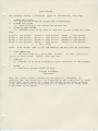
TABLE
OF
GAME
OPERATOR
SET UP
ADJUSTABLE
MELTDOWN
QUICK
CONTENTS
SERVICE
REFERENCE
GAME
SETTINGS
PROCEDURES
REPAIR
INITIALIZING
GAME
THE
PLAY
DISPLAY
TICKET DISPENSER
PARTS
(OPTIONAL)
LISTING
WARRANTY
SCHEMATICS
GAME SET UP
This game will be ready for
1.
The on/off switch located
be off.
2.
operation
after some minor adustments.
on the top panel on the cabinet should
Toggle the switch to the off position.
Pull out the electrical cord from the game
into a standard THREE
(3)
designed to operate on A.C.
WARNING:
A STANDARD THREE
FAILURE TO GROUND THE GAME
SERIOUSLY DAMAGE
base and plug cord
PRONG GROUNDED OUTLET.
voltage of
(3)
95-130
This model is
volts.
PRONG GROUNDED OUTLET MUST
WILL VOID YOUR
BE USED.
WARRANTY AND COULD
GAME ELECTRONICS AND MAY ALSO ADVERSELY AFFECT THE
SAFETY OF YOUR GAME AND CAUSE INJURY TO YOURSELF AND OTHERS.
OPERATOR
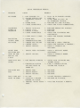
ADJUS T ABLE
SETT ING S
These adjustable setting are located on the P. C.
game,
on the rear of
Main
CO ST
Logic
Board
SW ITCH:
POS IT ION
T ICKET
#1
1 CO IN
2
2 CO INS
3
3 CO I N S
4
4
CO INS
SW ITCH:
POS IT ION
#1
1 ticket every round,
PO S IT ION
#2
1 ticket every other round,
POS IT ION
#3
Not used
PO S IT ION
#4
Not used
VOLUME CONTROL:
LOCATED ON
T IME PER ROUND
starting
SEC.
PER ROUND
1 OFF,
2 OFF
SEC.
PER ROUND
1 OFF,
2 ON
30
SEC.
PER ROUND
1 ON,
2 OFF
35 SEC.
PER ROUND
1 ON,
2 ON
IMPORTANT:
call I. C. E.
State
READ
PROCEED ING W ITH
starting at round 4
S IDE OF
THE BOARD.
SW ITCHES:
20
New York
4
BOARD
25
Any questions,
at round
THE LOWER LEFT HAND
D I SPLAY
In
Boards inside the
the chassis.
call
at 1-800-342-3433
1-716-693-9535
THROUGH
ALL
I N S TRUCT ION S
SERV ICE OR REPAIRS.
THOROUGHLY
BEFORE
MELTDOWN
NOTE:
SERVICE PROCEDURES
BEFORE PERFORMING ANY ROUTINE SERVICE,
THOROUGHLY INSPECT THE
WAY
THE
GAME
THIS WILL ASSIST YOU IN PROPER
SERVICE
BE SURE
TO
IS ASSEMBLED.
REASSEMBLY
AFTER
HAS BEEN PERFORMED.
OPENING THE GAME:
To open the game,
turn the lock located
top of the front display panel.
inside the
upper
with one hand
holding the
coin door.
pull
Turn the
forward on
behind the large tube at the
The key
for
lock
the top of
main cabinet with the
you
Pull
swing this leg
resting
the
against
marquis.
support leg rests on the
NOTE:
WE
will notice a U
Slowly
shaped support leg
out until it
lower the
chassis
stops
until
by
the
floor.
DO NOT RECOMMEND PLACING ANYTHING UNDER THE
SUPPORT LEG,
AS THE SUPPORT
CAUSING DAMAGE
When closing the
cabinet,
then
while
other hand.
folded inside.
and
is clipped
the large tube,
As the chassis tips forward,
up,
this lock
1/4 turn clockwise,
TO
game,
COULD
BECOME
UNSTABLE
THE UNIT.
swing
up the
support leg
and
slowly
making sure nothing hits on the cabinet edges.
close the
Secure the
lock.
SERVICING DRIVE CABLES AND RADIATION SHIELD
NOTE:
THE UPPER AND LOWER PULLEYS
OUT BY THEIR
IN
LOCATION WHEN THE
THE
GAME
GAME
ARE CALLED
IS IN OPERATING
POSITION.
For access to
the Radiation shield,
Remove the flat drive cable from
of the brackets
as
is
hinged
well as having the
The upper cable
bonus light and
holds this
bracket
the tube and ball
to come out
and place
tube
-- Remove the
Please note
round
when
in
Unclip the
just like the
can
upper
the
pulley bracket�.
inner
tube
and
this bracket
so be
to it.
prepared for
hinges
back.
lower
drive and idler
cables are routed
later be reassembled the
plugs found
Remove
location.
pulleys.
around the
same way.
modular phone plug on the display P.C. board.
phone
One
orange ball,
micro switch mounted
in a safe
cable from
cables:
position,
before removal the way the
pulleys so they
--
the
and retains the
the
ball and
or Drive
in residential homes.
through the hole in the cable containment channel
(the
Push
It looks
it
white plastic
extruded channel in the middle of this chassis).
-- Work the
cables around the game until the radiation shield can be
removed from the
tube.
It
will come
out by
the upper hinged bracket.
-- Remove the
like
common
cable
connectors from the
microphone
knurled lock ring then
pulling the
(THE CABLE ASSEMBLY CAN
-- If replacing the
follow
the
NOW
upper
following
radiation shield.
connectors and are removed by
the
connector straight out.
BE REMOVED FROM THE GAME
pulley
These are
unscrewing
cable
(4
conductor
IF
DESIRED)
flat
cable)
directions.
DO NOT CUT CABLE TIES TO SEPARATE ROUND
URETHANE CABLE FROM THE FLAT
4 CONDUCTOR CABLE AT THIS TIME.
Lay out the
cable next
original cable assembly and
to the
old
one.
put the
Note the location
new 4
cable ties connected to the flat cable. Cut the old
install the
new cable
in the exact
IT IS IMPO�TANT TO RETAIN THE
conductor
of the round
flat
cable and
cable ties,
and
same position.
ORIGINAL OVERALL LENGTH TO MAINTAIN
PROPER CABLE OPERATING TENSION.
Tighten the
tie,
cable ties as tight as possible
-- Reassemble
the
and snip off any excess
as on the original cable.
the radiation
cable down
through
THE ROUND CABLE IS
NOTE:
shield
the large
ATTACHED TO
RADIATION SHIELD AND THE
ATTACHED TO
Plug
into the
game,
THE BOTTOM
cable to the
top
-- Pull the
into the
cable into
the
botton of
the radiation shield.
of the
cable
around
and engage the
holding
cable
and
pull
bracket is
now
secured
-- Inspect to make
the
cable
cable containment
receptacle.
While
venturi.
the tube and ball
way
it
sure
with
in
drive pulleys.
holding the tube,
Put the
by hand,
around and engage the inner
While
BEND THE MICRO SWITCH WIRE).
Feed
the idler and
inner tube and ball.
hinged retainer bracket
--
is about half
tube.
Reinstall the
While
flat
shield.
cables around so the radiation shield
large
it in the large tube
flat
Guide the radiation
the tracks in the large tube and reconnect the
Install the round
tube.
OF THE
THE TOP.
the round
just into
first feeding
4 CONDUCTOR FLAT CABLE IS
(MAKE SURE THE SHIELD IS INSTALLED CORRECTLY).
shield
by
tube.
over
in
the two
swing
the
tube.
holding this bracket,
upper
pulleys.
slide
ball in the
upper
(DO NOT
grab
the
The retainer
place.
cables are on
the modular
channel and
snap
all pulleys and not twisted.
connectors through
into
the
the
display P.C.
hole in the
board
-- Start game
shield
and check for correct operation.
jumps or hangs up in the tracks,
is not twisted inside
If the radiation
check to see
that the cable
the cable containment channel.
disconnect the
modular connector,
reconnect it.
This will make the wire bend
If it is,
untwist it once or twice and
differently in the
containment channel.
SERVICING THE
-- Observe the
JOYSTICK AND LINKAGE
way the linkages are positioned when the
the venturi in the closed position.
linkage or spring,
joystick has
When replacing either the
be sure they do not bind on the aluminum bracket
that the venturi is mounted on.
--
To remove
springs,
the
joystick from the game,
and mounting screws.
has a nut
pn each end.
remove all linkages,
Then remove the cross link rod that
It is necessary to remove this link as the
joystick cannot be removed from the control panel,
joystick and handle are separated.
this link on at the
nuts
body.
and slide
The
the
sides of the
link out.
You
joystick
Now pull
unless the
will see the nuts that hold
body.
the
Remove one of the
handle out of the
joystick
joystick can now be removed from the game.
SERVICING THE NEON
LIGHTING SYSTEM
The neon lighting system is composed
interconnecting wire,
of two
straight neon tubes,
a high voltage transformer,
and all associated
mounting hardware and brackets.
WARNING:
THE NEON TRANSFORMER IN THIS GAME
OF ELECTRICITY,
WELL AS THE
TURN OFF
PRODUCES
POWER AT THE
2000 VOLTS
ON/OFF SWITCH AS
INTERLOCK SAFETY SWITCH TO AVOID POTENTIAL
INJURY.
When servicng the neon,
current can
make sure no bare wires are
jump small distances through the air,
exposed as
when there is no
insulation.
TO CHANGE NEON TUBES:
Turn off power.
Cut the tie wraps that secure the
Slide back the boots,
insulating boots.
and disconnect the Fast-on connectors by
pulling on them.
BE CAREFUL OF THE GLASS TUBES AS THEY ARE
COULD CAUSE SERIOUS INJURY.
FRAGILE
AND IF BROKEN,
Remove screws
from the clamps that hold the
the neon
the
neon
from
game.
Remove
and
save
neon
the
in
place.
boots that
Remove
protect the
from the clamps.
Install the
new tube(s)
caution when
by reversing the disassembly procedure.
tightening the clamps that secure
Make sure to secure the insulating
boots
the
neon
Use
in position.
with the tie wraps.
QUICK REFERENCE
REPAIR
PROBLEM
CAUSE
NO POWER
1.
NOT PLUGGED
1.
PLUG
2.
ON-OFF SWITCH OFF.
2.
TURN ON.
INTERLOCK
3.
3.
REMEDY
IN.
SWITCH
CLOSE GAME OR PULL UP
ON
OFF.
IN TO PROPER OUTLET.
INTERLOCK SWITCH.
4.
BLOWN FUSE.
4.
REPLACE W/2
5.
LOOSE CONNECTORS
5.
CHECK FOR TIGHT CONNECTIONS.
AMP
SLO-BLO.
INCORRECT
1.
FAULTY DISPLAYS
1.
REPLACE DEFECTIVE DISPLAY.
POWER UP
2.
FAULTY
6502
2.
REPLACE.
SEQUENCE
3.
FAULTY
E PROM
3.
REPLACE
4.
LOOSE CONNECTORS
4.
CHECK FOR
TIGHTNESS AND
CONTINUITY.
5.
LIGHT DON'T
LIGHT.
5.
CHECK FOR PROPER VOLTAGE.
1.
REPLACE.
2.
REPLACE.
3.
RADIATION
1.
MOTOR BAD
SHIELD DOES
2.
TRANSMISSION
NOT
3.
CABLES OFF
REPLACE &
CHECK TENSION.
4.
CABLES STUCK.
4.
CHECK
BINDING
5.
FAULTY WIRING.
5.
CHECK &
MOVE
BAD.
PULLEY
FOR
&
CORRECT.
CORRECT AS
NECSSARY.
MOTOR RUNS
BUT DOES
1.
FAULTY REED
SWITCHES1.
NOT
STOP AT THE
CHECK &
REPLACE WHERE
NECESSARY.
2.
FAULTY
WIRING.
2.
END OF ITS
CHECK
CORRECT
&
WHERE
NECESSARY.
LIMIT
GAME WILL NOT
1.
NOT ENOUGH
CREDITS
1.
START
CHECK COIN
SWITCHES AND
INSERT COINS.
2.
RADIATION SHIELD
DID
NOT
2.
FIND
&
SYSTEM
MOVE ON
CORRECT
DRIVE
FOR SHIELD.
POWER UP
FAN DOES NOT
1.
FAULTY FAN.
1.
REPLACE.
RUN
2.
FAULTY RELAY.
2.
REPLACE.
3.
FAULTY
3.
REPLACE.
WIRING.
BALL DOES NOT
1.
NO FAN.
1.
LOCATE PROBLEM
MOVE IN TUBE.
2.
JOYSTICK LINKAGE
2.
REPLACE OR
3.
LOOK FOR BINDING
BROKEN
3.
OR LOOSE.
VENTURI VALVE STUCK
SHUT.
CORRECTLY.
TIGHTEN.
&
REPAIR.
REMEDY
CAUSE
PROBLEM
RADIATION
1.
FAULTY
SHIELD
2.
BAD
3.
FAULTY
NOT
DOES
SENSE
BALL OR
FLAT
LIGHT
WIRING.
SENSORS.
4 CONDUCTOR
1.
CHECK
2.
REPLACE
3.
CHECK FOR CONTINUITY
REPLACE
CABLE.
&
REPAIR.
&
UNIT.
REPLACE IF NECESSARY.
4.
LOOSE
SENSOR
COVER.
4.
GAME SCORES
1.
LOOSE
SENSOR
COVER.
1.
REPLACE
COVER.
WHEN
2.
FAULTY WIRING.
2.
CHECK
CORRECT
RED
NOT
L. E. D. I s
BALL
IS
&
3.
FAULTY
SENSORS.
3.
REPLACE
SHIELD
4.
FAULTY
4 CONDUCTOR
4.
CHECK
FLAT
NO
SOUND
BONUSES
CABLE.
&
UNIT.
CONTINUITY
REPLACE IF
1.
FAULTY SPEAKER.
1.
2.
FAULTY
WIRING.
2.
REPLACE.
3.
VOLUME
TURNED
3.
TURN
4.
FAULTY
SOUND
4.
REPLACE.
1.
BAD
1.
REPLACE.
2.
SWITCH SHORTED
OUT.
2.
REPLACE.
3.
SWITCH TRIGGER
WIRE
3.
REBEND
MAIN
BENT,
DOWN.
CHIP.
BOARD.
KEEPING
BONUSES
NOT
VOLUME
WIRE
SWITCH
1.
FAULTY ·SWITCH.
1.
REPLACE.
2.
FAULTY
2.
REPLACE.
3.
REBEND
3.
WIRING
INCORRECTLY
WIRE
TRIGGER
BENT
NECESSARY.
REBLACE.
CLOSED.
COUNTED
AS
NECESSARY.
IN
RADIATION
NO
COVER.
UP.
GAME
The
game
must
complete the following power reset and initializing
before game play can
1.
begin:
Power is appplied
game as
INITIALIZING
well as
via the ON/OFF
the interlock
switch
swtich located on top of the
located on
the inside of
the
game.
2.
When
remain
test
the
power
lit until
is a self
turned on.
test
this
turned
power
on,
is
sequence
will
time the following
3.
is
the
the
neon and
turned
that
occurs
last approximately
will
The displays
will illuminate
b.
The fan
turn
c.
All
d.
The lights
After
lights in
the
power
each time the
20
seconds.
the temperature guage will
shield
lamp
is
During
this
reset the radiation
initialized and play
can
illuminate.
will illuminate.
shield
rest in the center area.
now
and
power
8's on all characters.
lower most limit and then to its upper most limit.
The game is
will light and
reset
on.
in the radiation
power up
marquee
The
occur:
a.
will
off.
begin.
will
travel
Finally
to its
coming to
GAME
1.
When the proper
amount of
(amount depending on
on the MAIN
P.C. assembly;
signaling
2.
be
see operator
the
acceptance of
The game will
emitted from the speaker
the credits.
begin when either one player or two player
A sharp electronic sound
will signal
the
buttons
beginning
of
game.
3.
The
the
ball activation.
radiation
4.
As the
shield will travel
to the lowest position awaiting
game begins the radiation shield will
approximately
the
the coin switch located
adjustable settings) the
be indicated on the display panel.
a sharp electronic sound
are depressed.
the
coins are placed in the coin acceptor
the switch position of
proper amount of credits will
There will
PLAY
the
middle of
the game allowing
ball to the center of the shield
is maintained points
L.E.D. 's lit
will
be added
to indicate the
rounds progress,
be raised to
the player to maneuver
where so long as this position
to the players score.
The
ball is in scoring position.
the shield will
be
moved
more often,
red
As the
and at a faster
rate.
5.
The sound
will
start
at
a low
tone
time counts the end of
the round.
6.
round
The length
depending on
assembly.
7.
of each
the switch
must
higher and
20,
30
25,
position located on the
(See operator
The player
is either
raising
adjustable
or
35
achieve a minimum
score in order
MELTDOWN
occurs and
the game will end.
points will
be offered
randomly
100
bonus
the red
signaled
bonus
by a
light.
back propelling the
tube.
If successful
points added
this score is not achieved,
to
will
8.
distinct
though the game.
bonus will shorten,
guage
The
lighting of
joystick all the way
bonus switch at the top of
a sharp electronic tone will
score.
continue to
the temperature
sound and the
must pull the
up to the
to the player
allowed for the
electronic
The player
ball
P.C.
settings).
If
bonus is
as
seconds
display
the next round.
raise until
higher
be emitted
As the rounds progress,
the
and
100
the time
increasing the difficulty.
THE DISPLAY
The display
1.
PLAYER
a.
6 different types of information;
conveys
ONE
SCORE
The actual
score
2.
PLAYER TWO SCORE
3.
SCORE TO NEXT ROUND
a.
they are:
of player
one
4 characters.
Same as player one accept for player two.
a.
Minimum
score to
be
made to
continue to next round the score
area:
100 points
Round
5
1900 points
Round
9
400 points
Round 6
2600 points
Round
10 6400 points
Round 3
800 points
Round
7
3400 points
Round 11
7600 points
Round 4
1300 points
Round
8
4300 points
Round
12
8900 points
1
Round
Round 2
ETC.,
NOTE:
4.
WITH VALUES
ETC.
10,000 THE LEADING ONE WILL NOT
OVER
BE
DISPLAYED.
TIME REMAINING
a .
The time
left
in a particular
"score to next round"
5.
5300 points
before
time
"round".
runs
out.
or
games
You
must reach
your
CREDITS
a.
6.
Purpose
is to
count
credits
available to the player.
ROUND
a.
Indicated
present round
of play.
TICKET DISPENSER
(Optional)
With
the ticket switch
position one,
round after
(located on
one ticket
round three
will
(3).
the
main P.C. assembly)
in
be dispensed at the completion
With
the
switch
in any
of every
other position
(2-4) one ticket will be dispensed at the completion of every other
round after
round
three.
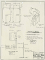
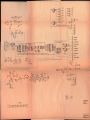
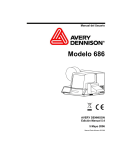
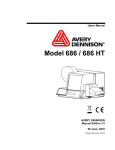
TICKET DISPENSER
MODEL DL-1275
PATENT NO. 4272001
1.
MECHANICAL DESCRIPTION OF OPERATION
The tickets are moved through the ticket shute by means of a power driven roller which
is spring loaded against an idler roller. The power driven roller is mounted on the output
shaft ot the motor gear train assembly. The motor assembly is mounted to the pivot bracket
assembly in two oilite bearings. The motor assembly has a limited free swing, limited by
the brake sprag. The brake sprag engages the power roller as an anti-theft device. With the
free swing of the motor assembly, the direction of torque, when electric power is applied,
is in a direction to release the brake sprag. When an attempt is made to pull tickets from
the. machine when power is off, the torque is reversed and the brake sprag is engaged. The
pulling of tickets also will cause the pivot bracket assembly to apply a pressure to the power
driven roller against the ticket and idler roller greater than the pre-set spring load.
2.
LOADING OF TICKETS
Tickets are entered into the rear of ticket shute and pushed forward. The power driven roller
will be spring loaded against the idler roller and tickets will not pass until rollers are clear of
each other. This is accomplished by use of thumb and index finger, one placed on the block
to which spring is attached, the other on the pivot bracket assembly, then squeeze. Push
tickets through until you see edge of ticket. Machine is now ready to operate.
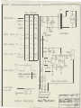
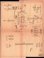
3.
ELECTRONIC SYSTEM
Attached to the ticket machine is a transistor motor controller, which provides dynamic braking
to ensure accurate and repeatable ticket stopping after issuing any number of tickets.
Included
as part of the controller is ticket sensing by means of an opto-electronic beam breaker sensor, which
senses the notch between tickets. The output of the ticket sensing circuitry is an open collector
transistor.
4.
ROLLER TENSION SPRING
The roller tension spring keeps constant tension on tickets, which insures proper delivery and
prevents tickets from being pulled through when the dispenser is idle. To increase tension,
loosen screw and move spring forward. Tension is adjusted correctly when tickets cannot be
pulled from dispenser.
5.
TICKET GUIDE SPRING
The ticket guide spring insures that the notches in the tickets pass through the opto-beam
breaker sensor. To increase tension, loosen screw and move outer spring up. This changes
the tension on the inner spring. Tickets should be snug between spring and side plate but
not deformed by excess tension. The spring is adjusted at the factory for 1-3/16" wide tickets.
6.
TICKET STOP ADJUSTMENT
The ticket stop adjustment allows positioning of tickets while the machine is off. The ticket
•
..
�.II
should protrude through the slot approximately 1/16". The ticket dispenser P.c·. board is
mounted with 2 screws in 2 slotted holes.
Loosening the screws and moving the board forward,
will allow the tickets to stop farther out beyond the edge of the slot.
(
r-
MOTOR
SUPPLY
MIN.
TYP.
M AX.
II V
12 v
13 v
-
1.3 A
1.5 A
I. 7 A
-
-
.4A
.85 A
(STANDBY)
-
-
30 MA
-V
I (START)
(RUN)
I
f
f
·.:p
•
1211 121---.-J
.I
7M fO.
•
I
I
MOTOR
MOTOR
TICKE T
ENABLE
ENABLE
NOTCH
-
ON
C'FF
-
-
V
+2.5 v
I
250UA
V
-
I
-
SINK- I
V
PULL-UP
-
--
+ 12
L- OFF BO AR D
v
2.5 MA
1
R8$2.2K
1.0 v
0
330().<' R2
-
50 MA
-
30 V
+�.,
IMfD.
I
z_
>:·: -=rl,_
MOTOR
ENABLE
MOTOR
STOPPED
MOTOR
RUN
I
MOTOR
STOPPE D
(0. C.
NOTCH
OUT PUT)
ov
---
r
Ul
H21 AI
_J
CD
<t:
z
w
>
-
N
+
TICKET
U2
w
v
c::
0
�
0
�
a
-
w
n::
3:
.......
4
�
I
c:i
z
(.!)
.X::
_J
m
.._,
3
74CI4
Tl CK ET
3
_J
�
2
tJ �IVN'�C -r�l€
INTERFACE
SPECIFICATIONS
NOTCH -(OUT PUT)
MDLE"X y,!;-(}3-09- 20�/
DELTRONIC
TICK.
DISP.
LABS
CONTROL
PAGE
3
IN C.
--
I 3I 2B3
rr·�
(
Fz
�+llTI+
I •
�
I•
34
�
I'
T
I
I
7.
's
�··
3
1\CK.EiS !1/\UST 14A\IE NOTC\-IES
BETWEEt-1 Et>.CI-I TICKET
4"
1L-t- j
3'
I 16
ON
\
l
+ij_i+
�·
1 8 X
.
� CUT
OUI
MODEL DL- 1275
(5TANDARD)
FRONT
IICK'ET
L
ON
I
3"
IG
I
MODELS:
PANELS
!I
(}I
�
lt DIA. T'1P.
DL-1275-V �·
DL-1275-H.
TICKET
STOP
5ENSOR. -
G.UIDE
01 RECT IONS:
TICI(ET5 AS INDICAiEO AND FEED TICKETS
TICKET GUIDE �PRING, UNTIL THE'( STOP.
SPRIN�
TIC KEI LOAD\ NG,
1.
ENTER
THE
2.
P. c.
CONTROL
80A.RD
3.
4.
PLACE FING.ERS AS INDICATED AND
THIS OPENS THE FEED ROLLERS.
5QUEEZ:E,
FEED 'TICKETS UNTIL \HE FIRSI "TICKET
PROTRUDE'S A.PPROX. I /110" 8E'IONO T\-\E DISPATCH
RELEt>.SE ROLLERS, TICK.EI
AND REA.D'I' FOR u5E.
PA.ST
DISPENSER
15 NOVJ
SLOT.
LOADED
TICK.ET!> CONT!>..CT:
"TICKET co.
TICKET A.VE.
SHAMOKIN, PA.. 1787C.
TEL: rlt- c;.4e- GB03
NA.IIONA.L
FOR
EXTERNAL
OUIPUT
iN ?U\5
-LTICKET
-{DRIVE
NOTCH
MOTOR. .�·
CONTROL LOC.IC
'POWER SUPPL '{
MOIOR
(o.c.)
BLU.
,
( + \/ )
(<"=..ND)
ENABLE
TICKET
HOOD
""'
'·
DISPENSER
LEN�TH:
HEIC:..HT:
WIDTH:
5- 1/Z"
4"
3- 116'
PANEL
"
- OISP.
PANEL
.....__TICKET
SLOT
HOOD KEEPS OUT COINS/
HELPS T O TEAR Off TICKETS �·------�
OlM.15
INC.
OELTRONtC LABS
RECOMMENDED
PANEL
TICKET
Dl5PEN5£R
PAG. E
4
--
I 32 � 8 4
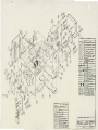
(
DETAILS OF"
f'I:\.RT5
IGl>ITY
OE"LTRONK.
1...t.l5 P/N
II
I
49-ol.-ZOI!!>
I Z.
I
49· A·ZOI8 MTJ1 PI'I01111(1 5Hol.FT
>/�
NAME
to..LR
ROW..�� �lin
13
I
49-A·ZOI•
PICT Eli(T �
14
Z.
49·A·ZPI7
51'0.CDI teo.,IXI(
I�
IE>
I
I
I
I
149-A·Z.OZOioC>-£1>
149 A·ZOZ.II Otto\/£
llou.LII.
•
ltCl..I..ER
17
TEN�ION
Ill
11\TI! Pl'o/OT
19
to
�z.
I I
I 1
I
z•
I
1
2.�
I
'
Z.!!i
�
Z.G
I
z.
1
I
I
z
I1
I
J0��HDS lf"'RRNT
149-8-ZOt!!il eou,l<£
,
:!I'Rt>K.,.
r,I(T,
At..�EL
5PI!A&.
I
........ zo,z LOCATI ... �1'1!1 ....
I41·A-ZOO.I'o" Rl...,
I �����L I PC. eo-'llO
1110-A- 47of>hl MOTOR
I49·B-20Z4IFR�"'E VU.TE
27
'28
z.�
;,o
�·
�2
��
Q.a
�·
&�
14
I
I
'
1
'
13"7-A-Z.OIOIP.C.
!IMtn. 771
BOAI!t> �
WIRE Cl-AM'P
lts-c-ooot I.I ...FO z•"·
I49·A-,Z9'1 �T....O OFI'
z.
4
�5
!5
�
2
26
MATERIAL
J'/N
CINTY
U 5 T FOR 5CR£W5
DESCRIPTION
I
12
4-�X
z
!5
4-40.
3
.s
4-40.
..
I
•-•z
•
I
i
li
:5
4
"4 Ft..."T
6
10
"4 $11\.IT 1,.()(., 'W...-111
7
I
-
!!.
9
•
WA$�E:R
DEL TRONIC LABS
INC.
,WMI
o.... aaa.wg
8 I"'.AT WASII:"R.
TICKET
'DISPENSER
PAGE
5
la.�5'1.
fN.,w.
18 83
-..o .
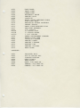
PARTS LIST
M101
MOTOR MOUNTING BRACKET
M102
LOWER PULLEY
BRACKET
M103
UPPER PULLEY
BRACKET
M104
LARGE TUBE SUPPORT BRACKET
M105
VENTURI
M106
NEON
SUPPORT BRACKET
CLAMP BRACKET
M107
INTERLOCK SWITCH BRACKET
M108
ON/OFF SWITCH
M109
BONUS LIGHT BRACKET
M110
MICRO SWITCH BRACKET
M111
200
MOUNTING
PLATE
MARQUIS BRACKET
-
100
TRANSFORMER TO MAIN AND LIGHTS
200
-
200
MAIN TO DISPLAY
200
-
300
MAIN TO DISPLAY
200
-
4.00
MAIN TO DISPLAY
UPPER
200
-
500
MAIN TO COUNTER
&
200 - 600
MAIN TO BONUS LIGHT
200
MAIN TO SPEAKER
-
700
200 - 800
MAIN TO MOTOR
200
RADIATION
-
900
&
LOWER SWITCHES
FAN
SHIELD INTERNAL
200
-
1000
DISPLAY
200
-
1100
TRANSFORMER TO MAIN
200
-
1200
A.C.
&
COIN DOOR
TO RADIATION SHIELD
FROM BLOCK TO FAN AND NEON
M201
MAIN PC BOARD
M202
DISPLAY
M205
INFRA-RED
M206
INFRA-RED RECEIVER
M207
TARGET CABLE
(SEE SEPARATE PARTS LISTING)
PC BOARD
(SEE SEPARATE PARTS LISTING)
EMITTER
M208
GAME COUNTER
M209
BONUS LIGHT
M210
MARQUIS LIGHT
M211
MARQUIS LIGHT SOCKET
M212
NEON LIGHT
M213
RADIATION SHIELD LED
M217
PLAY
M218
POWER SUPPLY
M219
NEON LIGHT
M220
MICRO SWITCH
M221
EXTERIOR
M223
SAFETY
INTERLOCK SWITCH
M225
BLOWER
FAN
M227
DRIVE MOTOR
BUTTON
TRANSFORMER
ON/OFF SWITCH
M234
RADIATION SHIELD CABLE CONNECTOR
M236
REED SWITCH ASSEMBLY
M237
NEON CABLE
M238
NEON BOOTS
M239
MODULAR PHONE CONNECTOR
M240
FAN RELAY
M300
MARQUIS
M301
FACE PANEL
M302
SMALL TUBE
M303
LARGE TUBE
M304
BUTTERFLY VALVE
M305
VENTURI BODY
M306
JOYSTICK
M307
BLACK ROUND URETHANE CABLE
M309
PING PONG BALL
M310
RADIATION SHIELD ASSEMBLY
M311
TARGET TRACKS
M313
SMALL TUBE RETAINER RING
M317
FAN/TUBE ASSEMBLY
M323
3/4"
M323A
1"
PULLEY FLAT
PULLEY ROUND
PULLEY
M323B
1"
M323C
1 3/4"
M325
CABLE
M327
BONUS LIGHT TUBE
PULLEY
CONTAINMENT
M504
JOYSTICK LINKAGE
M505
VENTURI SHAFT
M506
VENTURI LINKAGE
M512
SUPPORT
M513
VENTURI COLLARS
M515
NEON
CHANNEL
LEG
CLAMP
HARDWARE:
M601
SHOULDER BOLT
M602
#10-24 NYLOOK NUT
M603
LINKAGE BUSHING
M604
NEON CLAMPS
M605
NEON BOOTS
M606
MALE
M607
FEMALE
.250 FAST-ON
M608
FEMALE
.187
.250 FAST-ON
FAST-ON
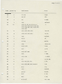
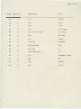
MELTDOWN MAIN BOARD
PARTS LIST
\._..,-
Item
1
Quantity
16
Reference
Part
R1,R2,R3,R4,R5,R9,R12
1K
R13,R18,R30,R34,R35,R36,
R135,R136,R137
2
1
U1
74LS365
3
2
R6,R132
150
4
1
D1
1N5908
5
1
U4
6502
6
1
U5
74LSOO
7
1
ti6
2532
8
1
U7
6810
9
1
U8
6522
10
1
U9
AY-3-8912
11
2
U10,U11
74LS138
12
3
U12,U13,U14
7417
13
2
U17,U3
74LS74
14
8
Q9,Q1,Q2,Q8,Q10,Q11,Q
TIP110
Q13
15
10
R59,R60,R61,R62,R63,R
1.2K
R65,R66,R67,R69
16
2
U15,U16
74LS164
17
5
Q14,Q5,Q15,Q16,Q18
TIS92
18
1
U2
74LS04
19
5
D3,D2,D4,D5,D6
1N4004
20
1
U19
LM358N
21
5
R14,R15,R23,R25,R40
lOOK
22
2
C16,C17
.47 POLY
23
4
Rl6,R24,R28,R32
470K
24
3
Rl7,R39,R48
22K
25
2
C2,C21
.01
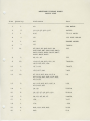
Page
Item
Quantity
Reference
Part
26
2
C3,C4
20pf
27
2
R8,R7
470
28
1
X1
4 MHZ
29
1
U41
LM78L05
30
21
C59,C1,C5,C6,C9,C10,C
.1
C12,C13,C14,C15,C18,C22,
C37,C38,C42,C43,C45,C53,
C55,C57
31
4
C62,C36,C39,C56
100/25
32
4
C54,C23,C25,C41
10/16
33
1
U42
LM7805
34
1
R131
47
35
2
o7;o8
MR752
36
1
C58
15000/16
37
2
R130,R31
220K
38
1
R27
4.7K
39
3
R29,R37,R41
100
40
1
R26
1 MEG
41
2
C20,C24
.1
42
1
C7
10/16 NP
43
4
C8,C28,C29,C30
1/50
44
6
R�O,R38,R42,R43,R44,R
10K
45
1
R11
270
46
1
U22
LM3080
47
2
Q6,Q7
TIS93
48
1
R47
6.2K
49
1
R46
3.9K
50
2
R33,R57
10K
POLY
VAR
2
of
3
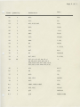
Page 3 of
'-._...,
Item
Quantity
Reference
Part
51
1
C27
47/35
52
1
C26
.001
53
1
R49
2.2K
54
1
C31
.033 POLY
55
4
C32,C33,C35,C40
.22 POLY
56
1
R50
50K VAR
57
"1
C61
220pf
58
2
U23,U24
TDA2002
59
3
R51,R53,R54
220
60
2
R52,R55
4.7
61
3
R134,R58,R133
2.2
62
1
SP1
SPEAKER 8
63
1
R56
47K
64
1
U18
MM5837
65
1
C60
10/25
OHM
3
MELTDOWN
DISPLAY
BOARD
PARTS LIST
Item
Quantity
Reference
Part
1
1
Ml
FAN MOTOR
2
5
Ql,Q2,Q3,Ql2,Q15
2N3906
3
1
R16
75/1/2 WATT
4
1
Kl
12V SPST RELAY
5
1
M2
TARGET MOTOR
6
1
U5
74LS14
7
21
R5,RNl,R2,RN2,RN3,R4
220
RN5,RN6,RN7,RN8,RN9,RN10,
RNll,RN12,RN14,RN16,RN17,
RN18,RN19,RN20
8
3
9
10
R6,Rl,R3
330
Ul4,U3,U4,Ul0,Ull,Ul
74LS164
Ul9,U25,U33,U34
10
2
Ul7,U22
74LS75
11
3
U35,U27,U41
7406
12
20
R7,Rl2,Rl3,R14,R15,R
1K
R20,R21,R22,R28,R34,R36,
R37,R38,R41,R45,R47,R50,
R52,R53
13
9
Rll,R9,Rl0,R23,R26,R
10K
R39,R42,R51
14
2
Q4,Q8
TIP32A
15
6
Q6,Q5,Q7,Q9,Ql0,Qll
TIPllO
16
5
D4,D3,D5,D6,D7
1N4004
17
1
U38
7437
18
1
C34
.068
19
4
R48,R24,R28,R46
lOOK
20
1
R49
51K
Page
Item
Quantity
Reference
Part
21
1
R32
100
22
1
C32
10
23
3
R31,R30,R43
10k
24
1
R29
300k
25
1
C28
.022
26
1
R40
510K
27
1
C29
220pf
28
1
R44
3.9K
29
1
D2
1N34
30
1
C27
1.0/50
31
1
R27
620
32
1
D1
1N4148
33
2
R17,R18
5.6/5W
34
26
C23,C1,C2,C3,C4,C5,C
.1
C8,C9,C10,C11,C12,C13,
C14,C15,C16,C17,C18,C19,
C20,C21,C22,C24,C30,C31
35
1
U32
4017
36
1
R8
10K
37
1
R35
39
38
2
U40,U39
LM358
39
1
R25
13K
40
3
LED1,LED2,LED3
LED
41
2
C25,C26
100uf
42
1
Q13
2N3904
43
1
Q14
PHOTO NPN
2
of
3
Page
Item
Quantity
Reference
Part
44
2
VR1,VR2
7805
45
1
R54
SELECT
46
1
C33
1. 0/50V
47
18
U2,U1,U6,U7,U8,U9,U1
74LS47
U13,U15,U16,U20,U21,U23,
U28,U30,U31,U36,U37
48
9
DIS2,DIS1,DIS3,DIS4,
DIS6,DIS7,DIS9,DIS10
MAN6610
3
of
3
MELTDOWN TEMPERATURE GUAGE BOARD
ITEM
QUANTITY
REFERENCE
PART
1
10
BULB GTE
2
10
SOCKET GTE 4 130
74
LIMITED WARRANTY
Seller .warrants that its printed c1rcuit boards and parts thereon are free from defects in material and workmanship
under normal use and service for a period of thirty (30) days from date of purchase of end user.
If the products described in this manual fail to conform to this warranty, Sellers' sole liability shall be, at its option, to
repair, replace, or credit Buyer's account for such products which are returned to Seller during said warranty period,
provided:
a.
Seller is promptly notified in writing upon discovery by Buyer that said products are defective;
b.
Such products are returned prepaid to Sellers' plant; and
c.
Sellers examination of said products discloses to Seller's satifaction that such alleged defects existed and were
not caused by accident, misuse, neglect, alteration, improper repair, installation or improper testing.
In no event shall Seller be liable for loss of profits, loss of use, incidental or consequential damages.
Except for any express warranty set forth in a written contract between Seller and Buyer which contract supersedes
the terms of this order, this warranty is expressed in lieu of all other warranties expressed or implied, including the
implied warranties of merchantability and fitness for a particular purpose, and of all other obligations or liabilities on
the Sellers' part, and it neither asumes nor authoizes any other person to assume for the Seller any other liabilities in
connection with the sale of products under this order.
The use of any non-I.C.E. parts and/or any alteration or modification to the machine's existing mechanical or
electronic parts may void your warranty according to the terms of the warranty. The use of any enhancer or update
kit and/or the use of any improperly grounded electrical outlet may also adversely affect the safety of your game and
cause injury to yourself and others. Be very cautious in using non-I.C.E. supplied components with our games,
in order to insure your safety.
I. C.E. distributors are independent, being privately owned and operated. In their judgement they may sell parts or
accessories other than I.C.E. parts or accessories. I. C. E. cannot be responsible for the quality, suitability or safety of
any non-I.C.E. part or any modification including labor which is performed by such distributor.
This document is and contains confidential trade secret information of I.C.E. Inc.
This document is loaned under confidential custody for the sole purpose of operation, maintenance or repair of
I.C.E. equipment and may not be used by or disclosed to any person for any other purpose whatever, and remains
the property of I.C.E., Inc.
Neither it nor the information it contains may be reproduced, used, or disclosed to persons not having a need to
know consistent with the purpose of the loan, without written consent of I.C.E., Inc.