1
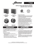
1-550.29 5H0707180000 February, 2015 INSTALLATION AND SERVICE MANUAL steam/hot water unit heaters C Model HSB Horizontal Delivery Top/Bottom Inlet/Outlet Model HC Horizontal Delivery Side Inlet/Outlet US General Information Installation and service instructions in this manual are applicable to the three types of steam/hot water unit heaters which should be installed in their proper applications for their most effective function as overhead heating units. The copper coils are warranted for operation at steam or hot water pressures up to 150 lbs. per sq. in. gauge, and or temperatures up to 375°F, cupronickel tube units are warranted for operating pressures up to 250 PSI and operating temperatures up to 400°F. Canadian Standards Association (CSA) requriements state that explosion-proof units may not be used with a fluid temperature in excess of 329°F and still maintain their explosion-proof rating, for national electric code ignition temperature rating T3B for grain dust. Models V/VN Vertical Delivery Model PT/PTN “Power-Throw” IMPORTANT The use of this manual is specifically intended for a qualified installation and service agency. A qualified installation and service agency must perform all installation and service of these appliances. Inspection On Arrival 1. Inspect unit upon arrival. In case of damage, report it immediately to transportation company and your local factory sales representative. 2. Check rating plate on unit to verify that power supply meets available electric power at point of installation. 3. Inspect unit received for conformance with description of product ordered (including specifications where applicable). Motors are designed for continuous duty. They can operate in a maximum ambient temperature of 104°F (40°C). The unit heaters are listed by the Canadian Standards Association as certified and Canadian Registered heat exchangers CRN OH 9234.5C. *Does not apply to V/PT 952. Caution Do not remove outlet fan guard from vertical type unit heaters. Steam horizontal and vertical delivery unit heaters are available in both standard and low-outlet temperature models. Low outlet temperature models are recommended primarily for installation on heating systems with steam pressures of 30 to 150 PSI. When used at these steam pressures they provide lower outlet air temperatures for longer heat throw and, because of wider fin spacing, they are less susceptible to clogging in dusty atmospheres. The model number of each unit heater indicates its rated Btu/Hr. capacity/1000 at 2 lbs. steam pressure and 60°F entering air temperature. For example an HSB 63 has an output of 63,000 Btu/Hr. at 2 lbs. steam and 60°F entering air. THIS MANUAL IS THE PROPERTY OF THE OWNER. PLEASE BE SURE TO LEAVE IT WITH the owner WHEN YOU LEAVE THE JOB. special precautions / table of contents / si (metric) conversion factors Special Precautions THE INSTALLATION AND MAINTENANCE INSTRUCTIONS IN THIS MANUAL MUST BE FOLLOWED TO PROVIDE SAFE, EFFICIENT AND TROUBLE-FREE OPERATION. iN ADDITION, PARTICULAR CARE MUST BE EXERCISED REGARDING THE SPECIAL PRECAUTIONS LISTED BELOW. FAILURE TO PROPERLY ADDRESS THESE CRITICAL AREAS COULD RESULT IN PROPERTY DAMAGE OR LOSS, PERSONAL INJURY, OR DEATH. THESE INSTRUCTIONS ARE SUBJECT TO ANY MORE RESTRICTIVE LOCAL OR NATIONAL CODES. HAZARD INTENSITY LEVELS 1. DANGER: Indicates an imminently hazardous situation which, if not avoided, WILL result in death or serious injury. 2. WARNING: Indicates a potentially hazardous situation which, if not avoided, COULD result in death or serious injury. 3. CAUTION: Indicates a potentially hazardous situation which, if not avoided, MAY result in minor or moderate injury. 4. Important: Indicates a situation which, if not avoided, MAY result in a potential safety concern. danger Appliances with power codes 01, 02, 04, 05, and 10 must not be installed where they may be exposed to a potentially explosive or flammable atmosphere. warning 1.Disconnect power supply before making wiring connections to prevent electrical shock and equipment damage. 2.All appliances must be wired strictly in accordance with wiring diagram furnished with the appliance. Any wiring different from the wiring diagram could result in a hazard to persons and property. 3.Any original factory wiring that requires replacement must be replaced with wiring material having a temperature rating of at least 105°C. 4.Ensure that the supply voltage to the appliance as indicated on the serial plate, is not 5% greater than the rated voltage. 5.When servicing or repairing this equipment, use only factory-approved service replacement parts. A complete replacement parts list may be obtained by contacting Modine Manufacturing Company. Refer to the rating plate on the appliance for complete appliance model number, serial number, and company address. Any substitution of parts or controls not approved by the factory will be at the owner’s risk. important 1. Start-up and adjustment procedures must be performed by a qualified service agency. 2. To check most of the Possible Remedies in the troubleshooting guide listed in Table 15.1, refer to the applicable sections of the manual. Table of Contents General Information............................................................... 1 Special Precautions............................................................... 2 SI (Metric) Conversion Factors.............................................. 2 Unit Location......................................................................... 3 Unit Mounting..................................................................... 3-4 Unit Suspension.................................................................... 5 Installation.......................................................................... 5-6 Piping................................................................................. 5 Electrical Connections....................................................... 5 Operation............................................................................... 6 Prior to Operation.............................................................. 6 Initial Start-up..................................................................... 6 Automatic Control Operations............................................ 6 General.............................................................................. 7 Performance Data............................................................ 8-11 Dimensional Data........................................................... 12-13 Motor Ampere Ratings......................................................... 14 Service................................................................................ 14 Service / Troubleshooting.................................................... 15 Warranty.................................................................Back Page Si (metric) conversion factors Table 2.1 To Convert Multiply By To Obtain "W.C. 0.249 kPa °F (°F-32) x 5/9 °C Btu 1.06 kJ 37.3 kJ/m Btu/ft Btu/hr 0.000293 kW CFH (ft /hr)0.000472 m /min CFH (ft /hr)0.00000787 m /s CFM (ft /min)0.0283 m /min CFM (ft /min)0.000472 m /s caution 1.Do not remove outlet fan guard from vertical type unit heaters. 2.Do not install units below 8 feet measured from the bottom of the unit to the floor. 3.Service or repair of this equipment must be performed by a qualified service agency. 4.Do not reuse any electrical component which has been wet. Replace component. 5.Ensure that the supply voltage to the appliance, as indicated on the serial plate is not 5% less than the rated voltage. 6.Heaters are designed for use in heating applications with ambient temperatures between 0°F and 100°F in hot water applications and -10°F to 100°F in steam applications. 2 1-550.29 3 3 3 3 3 3 3 3 3 3 To Convert Multiply By To Obtain feet 0.305 m Gal/Hr. 0.00379 m /hr Gal/Hr. 3.79 l/hr gallons 3.79 l Horsepower 746 W inches 25.4 mm pound 0.454 kg psig 6.89 kPa psig 27.7 "W.C. 3 unit location / unit mounting unit location Figure 3.3 - Combination Horizontal and Vertical Delivery Unit Installation danger Appliances with power codes 01, 02, 04, 05, and 10 must not be installed where they may be exposed to a potentially explosive or flammable atmosphere. 1. Units should not be installed in atmospheres where corrosive fumes or sprays are present. 2. Be sure no obstructions block air intake or air discharge of unit heater. 3. Locate horizontal delivery unit heaters so air streams of individual units wipe the exposed walls of the building with either parallel or angular flow without blowing directly against the walls. Heaters should be spaced so the air stream from one supports the air stream from another heater. See Figure 3.1. 4. Columns, machinery, partitions, and other obstacles should not interfere with air streams from unit heaters. 5. Unit heaters installed in a building exposed to a prevailing wind should be located to direct a major volume of heated air along the windward wall of the building. 6. Large expanses of glass, or large doors that are frequently opened, should be covered by long-throw unit heaters such as large horizontal delivery of “Power-Throw” unit heaters. 7. Vertical delivery unit heaters should generally be located in the central area of the space to be heated. Place horizontal delivery units along the walls of the same building where heat loss is usually greatest. See Figure 3.3. 8. Arrange horizontal delivery units so they do not blow directly at occupants. Air streams from this type of unit should be directed down aisles, into open spaces on the floor, or along exterior walls. 9. When only vertical delivery units are installed, they should be located so exposed walls are blanketed by their air streams. See Figure 3.2. Figure 3.1 - Horizontal Delivery Unit Location Figure 3.2 - Unit Locations of Vertical Units In Narrow Buildings Unit Mounting caution Do not install units below 8 feet measured from the bottom of the unit to the floor. Do not install unit above recommended maximum mounting heights. Height at which unit heaters are installed is critical. Maximum mounting heights for all units are listed in Table 4.1 and the height dimensions are shown in Figures 4.3 through 4.7. Maximum mounting heights for vertical models are given for units with or without optional air deflectors. The data in Table 4.1 is based on operating conditions of 2 lbs. steam or 220°F entering water with 60°F entering air. When operating conditions are other than those above, refer to Figure 4.2 for maximum mounting height correction factor. To obtain the maximum mounting at actual operating conditions, multiply the appropriate factor from Figure 4.2 by the mounting height in Table 4.1. The maximum mounting height for all units is that height above which the unit heater will not deliver heated air to the floor at standard rating conditions. Deflector Mounting If an optional air deflector has been furnished for vertical units, it is always shipped separately and can be attached to the unit before suspension. Vertical louvers for horizontal units and horizontal louvers for “Power-Throw” units can also be added and positioned before installation. Cone-jet and louver-type deflectors must be attached with angle brackets and machine screws to the bottom cover of the unit. Refer to mounting instructions which are furnished with each deflector. Depending on supply or return piping arrangement, there is a possibility of interference between certain anemostat air deflectors and piping on some vertical air delivery unit heaters. Check dimensions. 1-550.29 3 unit mounting Table 4.1 - Maximum Mounting Heights Horizontal Type Height (ft) Model No. Std. L.O.T. HSB/HC 18 8 9 HSB/HC 24 9 11 HSB/HC 33 10 12 HSB/HC 47 12 14 HSB/HC 63 14 16 HSB/HC 86 15 17 HSB/HC 108 17 19 HSB/HC 121 16 18 HSB/HC 165 19 21 HSB/HC 193 18 — HSB/HC 258 19 22 HSB/HC 290 20 23 HSB/HC 340 20 23 — — — — — — Power-Throw Type Height (ft) Model No. Std. L.O.T. — — — — — — — — — — — — — — — — — — — — — — — — — — — PT/PTN 279 16 — PT/PTN 333 17 — PT/PTN 385 17 — PT/PTN 500 18 — PT/PTN 610 20 22 PT 952 21 — Vertical Type with Deflectors No Deflector Cone-Jet Truncone Height (ft) Height (ft) Height (ft) Model No. Std. L.O.T. Std. L.O.T. Std. L.O.T. V/VN 42 11 13 15 17 8 9 V/VN 59 14 16 19 22 9 11 V/VN 78 15 19 20 26 11 14 V/VN 95 15 19 20 26 11 14 V/VN 139 18 23 24 31 13 17 V/VN 161 20 26 27 35 14 18 V/VN 193 22 27 30 36 16 19 V/VN 212 22 27 30 36 16 19 V/VN 247 26 32 34 42 17 21 V/VN 279 30 36 37 45 18 22 V/VN 333 30 36 37 45 17 20 V/VN 385 30 36 36 43 17 20 V/VN 500 37 45 44 54 19 24 V/VN 610 36 44 43 52 19 24 V 952 37 45 — — — — Louvers Height (ft) Std. L.O.T. 13 15 16 18 17 22 17 22 21 26 23 30 25 31 25 31 30 37 35 41 35 41 35 41 42 51 41 50 — — ➀ With horizontal louvers opened 30° from the vertical plane. HSB units have top and bottom piping connections, HC units have side connections. All have copper tubes. ➁ V and PT models have copper tubes, VN and PTN models have cupronickel tubes. Mounting heights are maximum for heaters operating at standard conditions (2 lbs. steam or 220°F water with 60°F entering air). Heights listed for Louver or Cone-Jet are with deflectors in fully-opened position. Refer to Figure 4.2 for correction of mounting heights under other operating conditions. Maximum mounting height will be reduced as entering air temperatures exceed 60°F. Correction Factor "R" Figure 4.2 - Maximum Mounting Heights Correction Factors 1.3 1.2 1.1 1.0 .9 .8 .7 .6 .5 150 2 160 170 180 190 200 210 220 5 10 230 240 Steam Pressure 30 50 20 250 260 270 280 290 70 300 310 150 100 320 330 340 350 360 370 Average Water Temp – F These correction factors are to be used as multipliers to correct the maximum recommended mounting heights of unit heaters when operated with steam pressures other than 2 pounds or with water at other than average temperature of 220°F. Figure 4.3 - Horizontal Unit Delivery Figure 4.4 - Vertical One-Way & Two-Way Louvers h h Figure 4.6 - Vertical Truncone Figure 4.3 - Vertical Cone Jet h 4 h h 1-550.29 h unit suspension / installation Unit Suspension Horizontal delivery units, Model HSB/HC Series. All horizontal delivery units, except Models HSB 18 and HSB 24, have two tapped holes in the top for unit suspension. HSB 18 and HSB 24 models do not require independent suspension and are installed directly on their supply piping. Models HSB 33-86 and HC 18-86 have 3/8"-16 tapped holes, model sizes 108 and larger have 1/2"-13 tapped holes. Piping support hangers or clamps are recommended and should be placed as close to the unit heater as possible. For other models, independent suspension can be made with threaded rods, pipes, or ceiling hanger brackets. See Figure 5.1. Vertical delivery units. Vertical delivery Models V/VN 42 through V/VN 279 have four tapped holes (1/2"-13) in the top cover for unit suspension. Unit suspension for these models can be made with threaded rods, pipes or ceiling hanger brackets. Models V/VN 333 through V/VN 952 are equipped with an angleiron mounting bracket that has eight 5/8" diameter hanger holes permitting hook-hoisting and suspension with cables, if desired. A 1/2" x 3" center U-bolt can be inserted in the two holes at each end of the bracket to accommodate suspension with four threaded rods, pipes or hanger brackets. "Power-Throw" horizontal delivery units. “Power-Throw” units are designed for horizontal air delivery and are equipped with hanger brackets for suspension. Three hanger brackets are supplied for Model PT/PTN 279, one on the front, and two on the rear panel for three-point suspension. Only two hanger brackets are furnished on the front panel of Models PT/PTN 333 through PT/PTN 952 (for required four-point suspension use the two hanger brackets on the front panel and the two holes on the ends of the upper angle supports at the rear of the unit). Each hanger bracket has a 5/8" diameter mounting hole for hookhoisting and suspension with threaded rods, pipes, or cables. Note: A pipe hanger adapter kit as illustrated in Figure 5.1 is available as an accessory from Modine. The kit consists of two drilled 3/4" I.P.S. pipe caps and two capscrews to facilitate threaded-pipe suspension. One kit will mount applicable HSB or HC models, two kits are required for V/VN models. Figure 5.1 - Unit Suspension 3. 4. 5. 6. 7. 8. water systems, include a balancing valve in return line for water flow regulation. A drain valve should also be provided below each unit heater to allow removal of water from the heating coil if located in an area subject to freezing. In steam or hot water systems, rapid air removal is required because entrained air is a cause of corrosion. Hot water systems should be equipped with suitable air vent valves for rapid and complete removal of air at the high points and ends of both supply and return mains. Proper air venting for steam systems can be achieved by use of a steam trap with an internal air vent. Traps must be located below the outlet of the unit. Consult trap manufacturer for specific recommendations. Each steam unit heater should be provided with a trap of sufficient size and capacity to pass a minimum of two times the normal condensate released by the unit at the minimum differential pressure in the system. Trap capacity is based on the pressure differential between supply and return mains. Steam systems should be equipped with a float and thermostatic trap or an inverted bucket trap with an air bypass. It is advisable to use a pipe line strainer before each steam trap draining a unit heater. This protection will reduce the maintenance of the steam trap. When strainers are used they should be installed between the unit heater and the trap and be the same size as the trap tapping. In order to catch dirt and scale, the strainer should have a screen perforation size smaller than the trap orifices. On systems where the steam supply to the unit heater is modulated or controlled by a motorized valve, a vacuum breaker should be installed between unit outlet and the trap. If a vacuum breaker is used, it should be in conjunction with a float and thermostatic trap. Install a scale pocket at bottom of unit heater to collect dirt and scale as shown in illustrations. Pipe diameter must be the same size as unit connections and about 6" long. Provide adequate pipe hangers, supports, or anchors to secure the piping system independently of the unit heater. Electrical Connections warning 1. Disconnect power supply before making wiring connections to prevent electrical shock and equipment damage. 2. All appliances must be wired strictly in accordance with wiring diagram furnished with the appliance. Any wiring different from the wiring diagram could result in a hazard to persons and property. 3. Any original factory wiring that requires replacement must be replaced with wiring material having a temperature rating of at least 105°C. 4. Ensure that the supply voltage to the appliance as indicated on the serial plate is not 5% greater than the rated voltage. caution Piping - See Figure 6.1 1. Branch piping to and from unit heater should include swing joints to allow for expansion and contraction of the piping without placing a strain on the unit heater element. On steam systems, the branch piping should be taken off and returned above the centerline of the supply and return lines. 2. Install pipe unions and shut-off valves in lines to and from each unit heater to allow maintenance or replacement of unit without shutting down and draining entire system. For hot 1. 2. 3. Do not install units below 8 feet measured from the bottom of the unit to the floor. Do not reuse any electrical component which has been wet. Replace component. Ensure that the supply voltage to the appliance, as indicated on the serial plate is not 5% less than the rated voltage. 1. Installation of wiring must conform with local building codes, or in the absence of local codes, with the National Electric Code ANSI/NFPA 70 - Latest Edition. Unit must be electrically grounded in conformance to this code. In Canada, wiring must comply with CSA C22.1, Electrical Code. 5 1-550.29 installation / operation Figure 6.1 - Suggested Piping Arrangements ➀ Hot Water Systems Horizontal Unit Heater Connected to Overhead Hot Water Mains Vertical Unit Heater Connected to Lower Hot Water Mains Steam Systems Unit Heater Connection for Low-Pressure Steam Open Gravity or Vacuum Return System Unit Heater Connection for High Pressure Steam ➀ Arrangements shown are recommendations only. Where horizontal units are shown, vertical units can be substituted or vice versa. For modifications to piping suggestions shown, refer to your local plumbing authority. Electrical Connections (Cont.) 2.Electric wiring must be sized to carry the full load amp draw of the motor, starter, and any controls that are used with the unit heater. All units with power codes 04, 05, 09, or 10 (polyphase motors) must be provided with suitable overcurrent protection in circuit supplying heater at installation. Overcurrent protectors should be sized based on motor current rating shown on the unit serial plate, and applicable national electric code procedures. All units are provided with an electrical junction box. Junction boxes are either integral to the motor or attached to the unit casing. Units with explosion-proof motors have an explosion-proof junction box attached to the motor. Any damage to or failure of Modine units caused by incorrect wiring of the units is not covered by Modine’s standard warranty. 3. Location of room thermostat, when supplied, should be in the natural circulating path of room air. Mount thermostat about five feet above floor level where it will not be affected by heat from the unit or other sources of drafts that would prevent it from properly controlling room temperature. See instructions packed with the thermostat. 4. Speed controllers furnished with specified unit heater fan motors, are packed separately and must be connected according to wiring diagram with each controller. operation Prior to Operation 1. Make sure fuses are installed in fused disconnect switches. 2. Check all electrical connections to assure they are secure. 3. Check rigidity of unit mounting. Tighten all fasteners, if necessary. 4. Inspect piping, strainers, traps, fittings, etc. Initial Start-Up 1. Set thermostat to lowest position. 2. Turn on power supply to unit. 3. Open return gate valve, and then open supply gate valve to unit. 4. Raise thermostat setting to desired position. 5. Adjust louvers (if provided) for desired heat distribution. 6. To insure proper sequence of operation, cycle unit on and off a few times by raising and lowering thermostat setting. 7. Check for proper rotation of fan. All fans must rotate in a counterclockwise direction when viewed from the back (HSB/HC, PT/PTN) or top (V/VN) of the unit heater. Automatic Control Operations Install one of the following operating systems for continuous automatic control. Intermittent Fan Operation — Hot Coil A room thermostat starts and stops the fan motor. An aquastat is sometimes strapped to the return piping to prevent fan operation when heat is not being supplied to the unit heater. Continuous Fan Operation — Intermittent Hot/Cold Coil A room thermostat controls a valve which opens to allow steam or hot water to supply the unit and closes to shut off the supply when the thermostat is satisfied. 6 1-550.29 OPERATION Figure 7.1 - Horizontal Delivery Unit Cutaway Connections — Female-type permits direct connection of unit heater to the piping. HC models have copper connectors at side of the unit. Vertical fins — Less opportunity for dust and dirt to collect. Reduces cleaning. Fins die-formed for added strength and heat transfer. Coil — All air passes through coil. Heating is uniform. Design assures maximum control over air delivery and temperature of air leaving the heater. Aluminum fins die-formed for added strength — increased heat transfer. Fins mechanically bonded to serpentine copper tube. Motor — All motors are totally enclosed. Single phase types include built-in thermal overload protection. All motor wiring is terminated in an electrical junction box either supplied on the unit heater or as an integral part of the motor. Fan — Lightweight. Blades accurately balanced and pitched to move air quietly and positively — with minimum power requirement. Safety fan guard — Standard equipment. Bolted steel rod fan guard completely surrounds the fan offering constant protection. Deflector blades — Adjustable horizontal air-deflector blades are standard — vertical blades are optional. Casings — Electrostatically applied, gray-green polyester powder coat paint finish is applied over rust- and corrosion-treated steel for long life. Figure 7.2 - Typical Horizontal Unit with Standard Junction Box Figure 7.3 - Horizontal Unit with Optional Fingerproof Fan Guard Figure 7.4 - Vertical Delivery Unit Cutaway Junction Box — Easier installation with single point electrical connection. Motor-Cooling Cone — Shields motor from coil heat — prolongs life of insulation, windings, and lubricant. Prolongs motor life. Motor easily removable — Modine design permits motor to be removed through opening below the unit — especially important where heaters are installed close to ceiling. Coil — Aluminum fins mechanically bonded to tubes for maximum heat transfer. All steam- and watercarrying passages between heavy steel pipe connections are copper, or cupronickel. Vertical fins — Less opportunity for dust and dirt to collect. Exposed for easy cleaning with air hose and brush. Motor — All motors are totally enclosed. Single phase types include built-in thermal overload protection. Casings — Electrostatically applied, gray-green polyester powder coat paint finish applied over rust- and corrosiontreated steel lasts longer. Fan — Accurately balanced to operate quietly and at lowest possible power consumption. 1-550.29 7 2 steam pERFORMANCE DATA - STANDARD MODELS lbs. STEAM 60° ENT. AIR Table 8.1 - Performance Data for Standard Units at Standard Conditions of 2 lb. Steam and 60°F Entering Air High Motor Speed Type Horizontal Delivery PowerThrow™ Vertical Delivery Model No. Btu/hr Sq. Ft. EDR HSB/HC 18 HSB/HC 24 HSB/HC 33 HSB/HC 47 HSB/HC 63 HSB/HC 86 HSB/HC 108 HSB/HC 121 HSB/HC 165 HSB/HC 193 HSB/HC 258 HSB/HC 290 HSB/HC 340 PT/PTN 279 PT/PTN 333 PT/PTN 385 PT/PTN 500 PT/PTN 610 PT 952 V/VN 42 V/VN 59 V/VN 78 V/VN 95 V/VN 139 V/VN 161 V/VN 193 V/VN 212 V/VN 247 V/VN 279 V/VN 333 V/VN 385 V/VN 500 V/VN 610 V 952 18,000 24,000 33,000 47,000 63,000 86,000 108,000 121,000 165,000 193,000 258,000 290,000 340,000 279,000 333,000 385,000 500,000 610,000 952,000 42,000 59,000 78,000 95,000 139,000 161,000 193,000 212,000 247,000 279,000 333,000 385,000 500,000 610,000 952,000 75 100 138 196 263 358 450 504 688 804 1,075 1,208 1,417 1,163 1,388 1,604 2,083 2,542 3,967 175 246 325 396 579 671 804 883 1,029 1,163 1,388 1,604 2,083 2,542 3,967 Maximum Mounting Height (ft.) 8 9 10 12 14 15 17 16 19 18 19 20 20 16 17 17 18 20 21 11 15 14 19 15 20 15 20 18 24 20 27 22 30 22 30 26 34 30 37 30 37 30 36 37 44 36 43 37 Heat Throw or Spread @ Max. Height 17 18 21 28 29 31 31 25 40 38 44 46 46 100 110 115 130 140 145 17 11 21 14 23 15 23 15 27 18 30 20 33 22 33 22 39 26 45 30 45 30 45 30 56 37 54 36 56 Air Data CFM Motor Data Outlet Final Air Condensate Velocity Temp. lb/hr (Fpm) (°F) 340 370 630 730 1,120 1,340 2,010 1,775 3,240 2,900 4,560 4,590 5,130 5,460 5,980 7,680 10,390 11,750 12,170 950 1,155 1,590 1,665 2,660 2,945 3,500 3,610 4,820 5,460 5,980 7,680 10,390 11,750 12,170 625 695 690 810 690 835 790 715 880 810 750 765 735 2,165 2,165 1,860 2,520 2,315 2,321 825 1,005 1,065 1,120 1,285 1,420 1,690 1,740 1,910 2,165 2,165 1,860 2,520 2,315 2,321 107 119 108 119 111 118 109 122 106 121 111 117 120 111 116 110 108 112 139 103 111 109 118 112 115 116 120 111 111 116 110 108 112 139 19 25 34 49 65 89 112 125 171 200 267 300 352 289 345 398 517 631 985 43 61 81 98 144 167 200 219 256 289 345 398 517 631 985 Hp Approx. RPM 1/60 1/25 1/25 1/12 1/12 1/8 1/8 1/5 1/3 1/3 1/2 1/2 1/2 1/2 3/4 1 1 1/2 1 1/2 2 1/30 1/30 1/15 1/15 1/6 1/3 1/3 1/3 1/2 1/2 3/4 1 1 1/2 1 1/2 2 1,550 1,550 1,550 1,550 1,550 1,625 1,625 1,075 1,075 1,075 1,075 1,075 1,075 1,075 1,140 1,140 1,140 1,140 1,140 1,050 1,050 1,050 1,050 1,075 1,075 1,075 1,075 1,075 1,075 1,140 1,140 1,140 1,140 1,140 Table 8.2 - Performance Data for Standard Units at Standard Conditions of 2 lb. Steam and 60°F Entering Air Reduced Motor Speed ➃ Air Data Type Model No. Btu/hr Sq. Ft. EDR Maximum Mounting Height (ft.) Heat Throw or Spread @ Max. Height CFM Horizontal Delivery HSB/HC 18 HSB/HC 24 HSB/HC 33 HSB/HC 47 HSB/HC 63 HSB/HC 86 HSB/HC 108 14,000 18,000 25,000 38,000 47,000 64,000 81,000 58 75 104 158 195 265 340 8 9 10 12 14 15 17 10 11 13 17 17 19 19 220 230 395 450 685 825 1,255 Motor Data Outlet Final Air Condensate Velocity Temp. lb/hr (Fpm) (°F) 415 440 440 515 430 525 500 118 131 118 137 122 131 119 14 19 26 39 49 66 84 Hp Approx. RPM 1/60 1/25 1/25 1/12 1/12 1/8 1/8 1,000 1,000 1,000 1,000 1,000 1,000 1,000 ➀ Horizontal units with horizontal louvers open 30° from vertical plane. Vertical types equipped with cone jet deflector, blades fully opened are shown in bold. ➁ CFM for horizontal types is entering CFM. CFM for vertical and "Power-Throw" types is leaving CFM. ➂ V and PT models have copper tubes, VN and PTN models have 90/10 cupro-nickel tubes. ➃ Requires Solid State Motor Speed Controller. 8 1-550.29 steam pERFORMANCE DATA - LOW OUTLET TEMPERATURE MODELS 2 lbs. STEAM 60° ENT. AIR Table 9.1 - Performance Data for Low Outlet Temperature Units at Standard Conditions of 2 lb. Steam and 60°F Entering Air High Motor Speed Type Model No. Btu/hr Sq. Ft. EDR Horizontal Delivery HSB/HC 18L HSB/HC 24L HSB/HC 33L HSB/HC 47L HSB/HC 63L HSB/HC 86L HSB/HC 108L HSB/HC 121L HSB/HC 165L HSB/HC 258L HSB/HC 290L HSB/HC 340L 15,900 19,300 29,500 32,000 52,500 61,500 86,500 88,000 143,000 190,000 207,000 255,000 66 80 123 133 219 256 360 367 596 792 863 1,063 Maximum Mounting Height (ft.) 9 11 12 14 16 17 19 18 21 22 23 23 PT/PTN 610L 470,000 1,958 22 V 42L V 59L V 78L V 95L V/VN 139L V/VN 161L V/VN 193L V/VN 212L V/VN 247L V/VN 279L V/VN 333L V/VN 385L V/VN 500L V/VN 610L V 952L 33,000 44,000 62,000 71,000 103,000 127,000 149,000 163,000 190,000 215,000 256,000 296,000 385,000 470,000 733,000 138 183 258 296 429 529 621 679 792 896 1,067 1,233 1,604 1,958 3,055 PowerThrow™ Vertical Delivery 17 22 26 26 31 35 36 36 42 45 45 43 54 52 - 13 16 19 19 23 26 27 27 32 36 36 36 45 44 45 Air Data Motor Data Heat Throw or Spread @ Max. Height 20 21 24 32 33 36 36 29 45 51 53 53 364 435 695 855 1,170 1,510 2,150 2,070 3,480 4,655 5,040 5,575 655 795 745 910 710 910 825 800 930 750 805 775 100 100 99 94 101 97 97 98 97 98 94 102 154 2,400 2,445 960 1,190 1,740 1,760 2,860 3,400 3,710 3,830 5,110 5,790 6,340 8,140 11,000 12,400 12,940 835 1,035 1,070 1,180 1,380 1,640 1,790 1,845 2,030 2,300 2,300 1,970 2,670 2,445 2,450 13 16 19 19 23 26 27 27 32 36 36 36 45 44 - 20 24 29 29 35 39 41 41 48 54 54 54 68 66 68 CFM Outlet Final Air Condensate Velocity Temp. lb/hr (Fpm) (°F) Hp Approx. RPM 16 20 31 33 54 64 90 91 148 197 214 264 1/60 1/25 1/25 1/12 1/12 1/8 1/8 1/5 1/3 1/2 1/2 1/2 1,550 1,550 1,550 1,550 1,550 1,625 1,625 1,075 1,075 1,075 1,075 1,075 97 486 1-1/2 1,140 94 96 95 99 95 96 99 102 96 96 100 95 94 97 115 34 45 65 73 106 132 154 169 197 222 265 307 400 485 759 1/30 1/30 1/15 1/15 1/6 1/3 1/3 1/3 1/2 1/2 3/4 1 1-1/2 1-1/2 2 1,050 1,050 1,050 1,050 1,075 1,075 1,075 1,075 1,075 1,075 1,140 1,140 1,140 1,140 1,140 Table 9.2 - Performance Data for Low Outlet Temperature Units at Standard Conditions of 2 lb. Steam and 60°F Entering Air Reduced Motor Speed ➃ Air Data Type Model No. Btu/hr Sq. Ft. EDR Maximum Mounting Height (ft.) Horizontal Delivery HSB/HC 18L HSB/HC 24L HSB/HC 33L HSB/HC 47L HSB/HC 63L HSB/HC 86L HSB/HC 108L 12,000 14,400 22,000 24,300 39,500 46,000 65,000 51 60 92 101 164 192 270 9 11 12 14 16 17 19 Heat Throw or Spread @ Max. Height CFM 12 13 14 19 20 22 22 230 265 430 540 725 925 1,330 Motor Data Outlet Final Air Condensate Velocity Temp. lb/hr (Fpm) (°F) 425 490 470 580 445 565 520 108 109 107 101 109 105 104 12 15 23 25 41 48 67 Hp Approx. RPM 1/60 1/25 1/25 1/12 1/12 1/8 1/8 1,000 1,000 1,000 1,000 1,000 1,000 1,000 ➀ Horizontal units with horizontal louvers open 30° from vertical plane. Vertical types equipped with cone jet deflector, blades fully opened are shown in bold. ➁ CFM for horizontal types is entering CFM. CFM for vertical and "Power-Throw" types is leaving CFM. ➂ V and PT models have copper tubes, VN and PTN models have 90/10 cupro-nickel tubes. ➃ Requires Solid State Motor Speed Controller. 1-550.29 9 Hot water pERFORMANCE DATA - STANDARD MODELS 200°F ENTERING WATER 60°F ENTERING AIR 20°F WATER TEMPERATURE DROP Table 10.1 - Performance Data for Standard Units at Standard Conditions of 200°F Entering Water and 60°F Entering Air High Motor Speed Water Data Type Horizontal Delivery PowerThrow™ Vertical Delivery Model No. Btu/hr HSB/HC 18 HSB/HC 24 HSB/HC 33 HSB/HC 47 HSB/HC 63 HSB/HC 86 HSB/HC 108 HSB/HC 121 HSB/HC 165 HSB/HC 193 HSB/HC 258 HSB/HC 290 HSB/HC 340 PT/PTN 279 PT/PTN 333 PT/PTN 385 PT/PTN 500 PT/PTN 610 PT 952 V/VN 42 V/VN 59 V/VN 78 V/VN 95 V/VN 139 V/VN 161 V/VN 193 V/VN 212 V/VN 247 V/VN 279 V/VN 333 V/VN 385 V/VN 500 V/VN 610 V 952 12,600 16,200 21,700 30,900 45,600 60,200 83,700 93,000 130,900 143,000 201,900 228,600 271,100 192,300 238,500 276,100 358,000 450,400 721,600 30,100 42,600 57,000 69,300 106,600 123,200 147,200 161,700 188,700 212,600 260,100 302,100 391,700 450,400 721,600 GPM 1.3 1.7 2.3 3.2 4.7 6.3 8.7 9.7 13.6 14.9 21.0 23.8 28.2 20.0 24.8 28.8 37.3 46.9 75.2 3.1 4.4 5.9 7.2 11.1 12.8 15.3 16.8 19.7 22.2 27.1 31.5 40.8 46.9 75.2 Pressure Drop (Ft. of Water) 0.5 0.8 0.2 0.4 0.6 1.0 2.8 3.3 8.6 1.4 5.7 7.1 11.3 0.2 0.4 0.6 0.5 1.0 1.1 0.6 0.5 0.5 0.5 2.6 2.2 2.2 1.5 2.1 2.1 3.8 5.0 4.8 1.0 1.1 Air Data Min/Max GPM 0.3 / 5.0 0.3 / 5.0 0.4 / 10.0 0.4 / 10.0 0.5 / 20.0 0.5 / 20.0 0.5 / 30.0 0.7 / 30.0 2.0 / 30.0 2.0 / 50.0 2.5 / 70.0 2.5 / 70.0 2.8 / 70.0 4.5 / 60.0 4.5 / 100.0 4.5 / 100.0 6.0 / 100.0 6.0 / 100.0 14.0 / 200.0 0.5 / 10.0 0.8 / 15.0 1.0 / 20.0 1.3 / 25.0 1.0 / 30.0 1.3 / 40.0 1.5 / 50.0 2.0 / 60.0 2.0 / 60.0 2.3 / 75.0 2.8 / 75.0 3.3 / 75.0 3.0 / 100.0 6.0 / 100.0 14.0 / 200.0 Maximum Mounting Height (ft.) Heat Throw or Spread @ Max. Height 9 10 11 13 15 16 18 17 20 19 20 22 22 17 18 18 19 22 23 18 19 23 30 31 33 33 27 43 41 47 50 50 108 117 124 138 151 150 12 15 16 16 19 21 23 23 28 32 32 32 39 38 39 16 20 22 22 26 29 32 32 37 40 40 39 47 46 18 22 24 24 29 32 35 35 41 48 48 48 59 57 59 12 15 16 16 19 22 24 24 28 32 32 32 40 39 CFM 340 370 630 730 1,120 1,340 2,010 1,775 3,240 2,900 4,560 4,590 5,130 5,460 5,980 7,680 10,390 11,750 12,166 950 1,155 1,590 1,665 2,660 2,945 3,500 3,610 4,820 5,460 5,980 7,680 10,390 11,750 12,166 Motor Data Outlet Final Air Velocity Temp. (Fpm) (°F) 615 675 675 785 680 820 775 700 870 790 740 750 720 2,165 2,165 1,860 2,520 2,315 2,321 825 1,005 1,065 1,120 1,285 1,420 1,690 1,740 1,910 2,165 2,165 1,860 2,520 2,315 2,321 93 100 91 98 97 101 98 107 96 105 100 105 108 94 99 95 93 97 120 90 96 95 101 99 101 101 104 98 98 102 98 96 97 120 Hp Approx. RPM 1/60 1/25 1/25 1/12 1/12 1/8 1/8 1/5 1/3 1/3 1/2 1/2 1/2 1/2 3/4 1 1 1/2 1 1/2 2 1/30 1/30 1/15 1/15 1/6 1/3 1/3 1/3 1/2 1/2 3/4 1 1 1/2 1 1/2 2 1,550 1,550 1,550 1,550 1,550 1,625 1,625 1,075 1,075 1,075 1,075 1,075 1,075 1,075 1,140 1,140 1,140 1,140 1,140 1,050 1,050 1,050 1,050 1,075 1,075 1,075 1,075 1,075 1,075 1,140 1,140 1,140 1,140 1,140 Table 10.2 - Performance Data for Standard Units at Standard Conditions of 200°F Entering Water and 60°F Entering Air Reduced Motor Speeds ➃ Water Data Type Model No. Btu/hr Horizontal Delivery HSB/HC 18 HSB/HC 24 HSB/HC 33 HSB/HC 47 HSB/HC 63 HSB/HC 86 HSB/HC 108 9,900 12,400 16,700 23,600 34,600 45,900 64,300 GPM 1.3 1.7 2.3 3.2 4.7 6.3 8.7 Air Data Maximum Heat Throw Pressure Mounting or Spread @ Drop (Ft. Height (ft.) Max. Height of Water) 0.5 0.8 0.2 0.4 0.6 1.0 2.8 9 10 11 13 15 16 18 11 12 14 18 18 20 20 Motor Data CFM Outlet Velocity (Fpm) Final Air Temp. (°F) Hp Approx. RPM 220 230 395 450 685 825 1,255 400 425 430 490 420 515 490 101 109 98 107 106 110 106 1/60 1/25 1/25 1/12 1/12 1/8 1/8 1,000 1,000 1,000 1,000 1,000 1,000 1,000 ➀ Horizontal units with horizontal louvers open 30° from vertical plane. Vertical types equipped with cone jet deflector, blades fully opened are shown in bold. Non-bolded mounting height/spread data is for units without deflectors. ➁ CFM for horizontal types is entering CFM. CFM for vertical and "Power-Throw" types is leaving CFM. ➂ V and PT models have copper tubes, VN and PTN models have 90/10 cupro-nickel tubes. ➃ Requires Solid State Motor Speed Controller. 10 1-550.29 HOT WATER PERFORMANCE DATA - LOW OUTLET TEMPERATURE MODELS 20°F WATER TEMPERATURE DROP Table 11.1 - Performance Data for Low Outlet Temperature Units at Standard Conditions of 200°F Entering Water and 60°F Entering Air – High Motor Speed Water Data Pressure Drop (Ft. of Water) Min/Max GPM CFM 0.4 0.6 0.2 0.2 0.4 0.6 1.8 1.9 6.6 3.2 3.7 6.6 0.3 / 5.0 0.3 / 5.0 0.4 / 10.0 0.4 / 10.0 0.5 / 20.0 0.5 / 20.0 0.8 / 30.0 0.8 / 30.0 2.0 / 30.0 2.5 / 70.0 2.5 / 70.0 2.5 / 70.0 10 12 13 15 17 18 20 19 23 23 25 25 21 22 26 34 35 38 38 31 48 54 57 57 364 435 695 855 1,170 1,510 2,150 2,070 3,480 4,655 5,040 5,575 650 775 730 890 695 890 815 785 920 735 800 760 24 158 12,400 960 1,190 1,740 1,760 2,860 3,400 3,710 3,830 5,110 5,790 6,340 8,140 11,000 12,400 12,800 Btu/hr Horizontal Delivery HSB/HC 18L HSB/HC 24L HSB/HC 33L HSB/HC 47L HSB/HC 63L HSB/HC 86L HSB/HC 108L HSB/HC 121L HSB/HC 165L HSB/HC 258L HSB/HC 290L HSB/HC 340L 11,300 13,700 19,300 21,100 37,900 44,600 66,100 66,700 113,200 147,400 161,100 200,900 1.2 1.4 2.0 2.2 4.0 4.6 6.9 6.9 11.8 15.4 16.8 20.9 PT/PTN 610L 344,900 35.9 0.6 6.0 / 100.0 V 42L V 59L V 78L V 95L V/VN 139L V/VN 161L V/VN 193L V/VN 212L V/VN 247L V/VN 279L V/VN 333L V/VN 385L V/VN 500L V/VN 610L V 952L 23,000 32,600 43,600 53,100 81,200 93,900 112,500 123,400 143,600 162,200 198,300 229,100 295,000 344,900 546,700 2.4 3.4 4.5 5.5 8.5 9.8 11.7 12.9 15.0 16.9 20.7 23.9 30.7 35.9 56.9 0.4 0.3 0.3 0.3 1.6 1.3 1.3 0.9 1.2 1.2 2.3 3.0 2.8 0.6 0.7 0.5 / 10.0 0.8 / 15.0 1.0 / 20.0 1.3 / 25.0 1.0 / 30.0 1.3 / 40.0 1.5 / 50.0 2.0 / 60.0 2.0 / 60.0 2.3 / 75.0 2.3 / 75.0 2.3 / 75.0 3.0 / 100.0 6.0 / 100.0 14.0 / 100.0 PowerThrow™ Vertical Delivery Motor Data Heat Throw or Spread @ Max. Height Model No. GPM Air Data Maximum Mounting Height (ft.) Type 14 17 20 20 24 28 29 29 34 38 38 38 48 47 48 18 23 28 28 33 37 38 38 45 48 48 46 57 55 - 200°F ENTERING WATER 60°F ENTERING AIR 21 25 31 31 37 41 43 43 51 57 57 57 72 70 72 14 17 21 21 25 28 29 29 35 39 39 49 49 48 - Outlet Final Air Velocity Temp. (Fpm) (°F) Hp Approx. RPM 88 88 85 82 89 87 88 89 89 89 89 93 1/60 1/25 1/25 1/12 1/12 1/8 1/8 1/5 1/3 1/2 1/2 1/2 1,550 1,550 1,550 1,550 1,550 1,625 1,625 1,075 1,075 1,075 1,075 1,075 2,445 86 1-1/2 1,140 835 1,035 1,170 1,180 1,380 1,640 1,790 1,845 2,030 2,300 2,300 1,970 2,670 2,445 2,440 83 86 84 89 87 86 89 91 87 87 90 87 85 86 102 1/30 1/30 1/15 1/15 1/6 1/3 1/3 1/3 1/2 1/2 3/4 1 1-1/2 1-1/2 2 1,050 1,050 1,050 1,050 1,075 1,075 1,075 1,075 1,075 1,075 1,140 1,140 1,140 1,140 1,140 Table 11.2 - Performance Data for Low Outlet Temperature Units at Standard Conditions of 200°F Entering Water and 60°F Entering Air – Reduced Motor Speeds ➃ Water Data Type Model No. Btu/hr Horizontal Delivery HSB/HC 18L HSB/HC 24L HSB/HC 33L HSB/HC 47L HSB/HC 63L HSB/HC 86L HSB/HC 108L 8,700 10,400 14,700 16,300 29,000 33,900 50,500 Air Data Motor Data GPM Pressure Drop (Ft. of Water) Maximum Mounting Height (ft.) Heat Throw or Spread @ Max. Height CFM Outlet Velocity (Fpm) Final Air Temp. (°F) Hp Approx. RPM 1.2 1.4 2.0 2.2 4.0 4.6 6.9 0.4 0.6 0.2 0.2 0.4 0.6 1.8 10 12 13 15 17 18 20 13 14 16 21 21 23 23 230 265 430 540 725 925 1,330 410 475 455 570 435 550 510 94 95 91 87 96 93 94 1/60 1/25 1/25 1/12 1/12 1/8 1/8 1,000 1,000 1,000 1,000 1,000 1,000 1,000 ➀ Horizontal units with horizontal louvers open 30° from vertical plane. Vertical types equipped with cone jet deflector, blades fully opened are shown in bold. Non-bolded mounting height/spread data is for units without deflectors. ➁ CFM for horizontal types is entering CFM. CFM for vertical and "Power-Throw" types is leaving CFM. ➂ V and PT models have copper tubes, VN and PTN models have 90/10 cupro-nickel tubes. ➃ Requires Solid State Motor Speed Controller. 1-550.29 11 DIMENSIONAL DATA Horizontal Air Delivery Models — Two Styles Figure 12.1 - Model Dimensions HSB 18-193 Figure 12.2 - Model Dimensions HSB 258-340 MOUNTING HOLES SIZES 33-86, 3/8"-16 TAP SIZES 108-193, 1/2"-13 TAP Mounting Holes Mounting Holes 1/2" - 13 Tap B B E G (MOUNTING HOLES) F (PIPE CONNECTIONS) E Pipe Connections G F Wall A A C D 5" MIN Figure 12.3 - Model Dimensions HC 18-165 Mounting Holes 1/2" - 13 Tap G (MOUNTING HOLES) H (PIPE CONNECTION) E 5" Min. Figure 12.4 - Model Dimensions HC 193-340 ➀ MOUNTING HOLES SIZES 33-86, 3/8"-16 TAP SIZES 108-165, 1/2"-13 TAP B D C Mounting Holes B E F G Pipe Connections H A Wall A C D 5" MIN Table 12.1 - Model HSB and HC Dimensions ➀ ➁ Model Number A B C HSB 18 12-3/8 13 6 HSB 24 12-3/8 13 6 HSB 33 16-3/8 17-1/2 8-3/4 HSB 47 16-3/8 17-1/2 8-3/4 HSB 63 20-7/16 21-1/2 8-3/4 HSB 86 20-7/16 21-1/2 8-3/4 HSB 108 24-7/16 25-1/2 9-1/2 HSB 121 24-7/16 25-1/2 9-1/2 HSB 165 30-1/2 30-1/2 9-1/4 HSB 193 30-1/2 30-1/2 9-1/4 HSB 258 38-1/2 38-1/2 12-1/2 HSB 290 38-1/2 38-1/2 12-1/2 HSB 340 38-1/2 44-1/2 12-1/2 HC 18 11-1/2 12-3/4 6 HC 24 11-1/2 12-3/4 6 HC 33 15 17-1/2 8-3/4 HC 47 15 17-1/2 8-3/4 HC 63 18-1/2 21-1/2 8-3/4 HC 86 18-1/2 21-1/2 8-3/4 HC 108 22-1/2 25-1/2 9-1/2 HC 121 22-1/2 25-1/2 9-1/2 HC 165 26-1/2 29-1/2 9-1/4 HC 193 30-1/2 32-1/2 9-1/4 HC 258 38-1/2 38-1/2 12-1/2 HC 290 38-1/2 38-1/2 12-1/2 HC 340 38-1/2 44-1/2 12-1/2 C 5" Min. ➀V ertical deflector blades shown are standard on models HC 258-340 and optional on model HC 193. DFemale Approx. 115 Std. 115V Exp. Connections Fan Shipping Motor Motor E F G H NPT Diameter Wt. lb. 5 12 - 3 - - 3/4 9 16 6-1/2 12 - 3 - - 3/4 9 20 6-1/2 12-1/4 11 3-5/8 6 - 1-1/4 12 34 8 12-1/4 11 3-5/8 6 - 1-1/4 12 36 8 12-3/4 15 3-5/8 6 - 1-1/4 14 48 9 12-3/4 15 3-5/8 6 - 1-1/4 14 52 8 11-1/2 18 3-3/4 6-3/8 - 1-1/4 18 74 7-1/2 11 18 3-3/4 6-3/8 - 1-1/4 18 76 9-1/2 14 21-1/4 3-3/4 6-3/8 - 1-1/4 22 92 9-1/2 14 21-1/4 3-3/4 6-3/8 - 1-1/4 22 98 10-1/2 14 18-1/2 3-5/8 7-7/8 - 1-1/4 22 162 10-1/2 14 18-1/2 3-5/8 7-7/8 - 1-1/4 24 168 10-1/2 14 18-1/2 3-5/8 7-7/8 - 1-1/4 24 176 5 12 5-5/8 2-1/4 4-1/8 7-1/2 1/2 9 16 6-1/2 12 5-5/8 2-1/4 4-1/8 7-1/2 1/2 9 20 6-1/2 12-1/4 11 3-5/8 6 10 3/4 12 34 8 12-1/4 11 3-5/8 6 10 3/4 12 35 8 12-3/4 15 3-5/8 6 14 3/4 12 48 9 12-3/4 15 3-5/8 6 14 3/4 14 52 8 11-1/2 18 3-5/8 6-3/8 18 3/4 18 74 7-1/2 11 18 3-5/8 6-3/8 18 3/4 18 76 9-1/2 14 21-1/4 3-5/8 6-3/8 22 3/4 22 92 9-1/2 14 21-1/4 3-5/8 4-3/4 26 1-1/4 22 98 10-1/2 14 18-1/2 3-5/8 8 34 1-1/4 22 163 10-1/2 14 18-1/2 3-5/8 8 34 1-1/4 24 168 10-1/2 14 18-1/2 3-5/8 8 34 1-1/4 24 176 ➀ All dimensions in inches. Dimensions shown are for Standard and Low Outlet Temperature Models. 12 D 1-550.29 DIMENSIONAL DATA Figure 13.1 - Model Dimensions V/VN and PT/PTN Vertical Air Delivery “Power-Throw” Air Delivery Air Deflectors (Optional) Table 13.1 - Model V/VN and PT/PTN Dimensions ➀ ➁ ➂ Male Connections Approx. Model Fan NPT Shipping Number A B C D E F G Diameter Top Bottom Wt. (lb.) V/VN 42 24-3/43-5/8 11-3/82-1/8 4-3/8 14-1/2 - 14 1-1/4 1-1/4 36 V/VN 59 24-3/45-1/8 11-3/82-1/8 4-3/8 14-1/2 - 14 1-1/4 1-1/4 42 V/VN 78 24-3/46-5/8 11-3/82-1/8 2-5/8 16-1/2 - 16 1-1/4 1-1/4 46 V/VN 95 24-3/48-1/8 11-3/82-1/8 2-5/8 16-1/2 - 16 1-1/4 1-1/4 48 V/VN 139 34-3/46-7/8 18-3/82-1/8 3 19-1/2 - 19 1-1/2 1 70 V/VN 161 34-3/48-3/8 18-3/82-1/8 3 19-1/2 - 19 1-1/2 1 80 V/VN 193 34-3/49-7/8 18-3/82-1/8 3 19-1/2 - 19 1-1/2 1 86 V/VN 212 34-3/412-7/8 18-3/8 2-1/2 3 19-1/2 - 19 2 1-1/4 94 V/VN 247 34-3/412-7/8 18-3/8 2-1/2 3 21-1/2 - 21 2 1-1/4 108 V/VN 279 34-3/414-3/8 18-3/8 2-1/2 3 21-1/2 - 21 2 1-1/4 112 V/VN 333 43-1/414-5/831-1/22-7/8 3-1/8 22-1/218-1/5 22 2-1/2 1-1/2 166 V/VN 385 43-1/414-1/231-1/22-7/8 3-1/2 27-1/218-1/5 27 2-1/2 1-1/2 168 V/VN 500 43-1/4 19 31-1/22-7/8 3-1/2 27-1/218-1/5 27 2-1/2 1-1/2 360 V/VN 610 51-1/219-1/831-3/8 - 3-3/4 30-1/231-3/8 30 2-1/2 1-1/2 450 V 952 53-3/421-1/8 30 - 3-1/2 31 30 30 3 3 487 PT/PTN 27934-3/422-5/8 25-1/416-3/416-3/4 - - 21 2 1-1/4 122 PT/PTN 33343-1/423-7/8 30 15-3/414-3/8 - - 22 2-1/2 1-1/2 176 PT/PTN 38543-1/425-3/4 30 15-3/414-3/8 - - 27 2-1/2 1-1/2 184 PT/PTN 500 43-1/429 3020-1/4 14-3/8 - - 27 2-1/2 1-1/2 376 PT/PTN 610 51-1/2 29-5/8 3020-3/821 - - 30 2-1/2 1-1/2 472 PT 952 53-3/426-3/8 30 23-1/826-7/8 - - 30 3 3 487 ➀ All dimensions in inches. ➁ Dimensions shown are for Standard and Low Outlet Temperature Models. ➂ See Table 13.2 for optional air outlet accessory dimensions. Table 13.2 - Vertical Air Outlet Accessories Dimensions ➀ Model Cone-Jet Number L T V 42, V 59 6-1/2 18-7/8 V 78, V 95 6-1/2 18-7/8 V 139, V 212 7-1/2 24-3/4 V 247, V 279 8 26-7/8 V 333 8-1/2 28 V 385, V 500 10 22-3/4 V 610 10-1/2 36-3/4 V 952 - - Truncone Louvers M X P Z 12 22 6-1/2 16-7/8 12 22 6-1/2 16-7/8 13 27 7-1/2 19-3/4 16 34 8 22-3/4 16 34 8-1/2 22-3/4 21 41 10 27-3/4 21 41 10-1/2 30-3/4 - - 19-1/2 32 ➀ All dimensions in inches. 1-550.29 13 motor Data / Service Table 14.1 - Motor Amp Draw Data ➀ ➁ Amp Draw by Motor Type, Voltage and Power Code Totally Enclosed Explosion Proof 115/60/1 208/60/1 230/60/1 208/60/3 230/460/3 575/60/3 115/60/1230/460/60/3 Model Number Motor HP ➂ 01N/A 0204 0510 0609 HSB/HC 18 1/600.8 ➃0.44 ➃ ➃ ➃4.3 HSB/HC 24, 33 1/251.6 ➃1.0 ➃ ➃ ➃4.3 HSB/HC 47, 63 1/123.0 ➃1.0 ➃1.4/0.7 ➄ ➃4.3 HSB/HC 86, 108 1/82.3➃1.0 ➃1.4/0.7 ➄ ➃4.3 HSB/HC 121 1/52.8➃ 1.51.9 ➄2.1/1.05 ➄ ➃ 4.01.4/0.7 HSB/HC 165, 193 1/35.4➃ 2.51.9 ➄2.1/1.05 ➄ ➃ 6.51.4/0.7 HSB/HC 258-340 1/26.7➃ 3.52.6 ➄3.0/1.5 ➄ ➃ 9.02.0/1.0 V/VN 42, 59 1/302.1 ➃ 0.61.9 ➄2.1/1.05 ➄ ➃4.0 V/VN 78, 95 1/152.5 ➃ 1.31.9 ➄2.1/1.05 ➄ ➃4.0 V/VN 139 1/52.8➃ 1.51.9 ➄2.1/1.05 ➄ ➃ 4.01.4/0.7 V/VN 161-212 1/35.4➃ 2.51.9 ➄2.1/1.05 ➄ ➃ 6.51.4/0.7 V/VN 247 1/26.7➃ 3.52.6 ➄3.0/1.5 ➄ ➃ 9.02.0/1.0 V/VN, PT/PTN 279 1/26.7➃ 3.52.6 ➄3.0/1.5 ➄ ➃ 9.02.0/1.0 V/VN, PT/PTN 333 3/48.8➃ 4.43.7 ➄3.4/1.7 ➄ ➃- V/VN, PT/PTN 385 1 - - - 4.2 4.0/2.01.5 - 3.5/1.75 V/VN, PT/PTN 500, 610 1-1/2 - - - 7.4 6.6/3.32.0 - 5.8/2.9 V, PT 952 2 - - - 7.4 6.8/3.4- -6.2/3.1 ➀ Ratings shown are for Standard and Low Outlet Temperature Models. ➁ All motors include thermal overload protection except for units with power code 04, 05, or 10. ➂ All HSB/HC units, V/VN 42 thru V/VN, PT/PTN 333 motor HP listed for power code 01. V/VN, PT/PTN 333 thru V/VN, PT/PTN 610 motor HP listed for power code 04 and V/PT 952 motor HP listed for power code 05. ➃ For supply voltages of 208V/60Hz/1ph and all non-explosion proof 3 phase voltages of 208, 230, 460 and 575, Model Numbers indicated with Note ➃, require that a 115V/60Hz/1 phase power code 01 unit heater be used with a shipped loose accessory transformer. See literature #1-556 for Transformer Sizes. See Note ➄. ➄ Model numbers indicated with Note ➄, can be ordered with a power code (208V/3ph=04, 230/460V/3ph=05) that provides a motor matched to the supply voltage with amp draw as shown. Alternately, a 115V/60Hz/1 phase power code 01 unit heater could be used with a shipped loose accessory transformer. See literature #1-556 for Transformer Sizes. service Motors warning When servicing or repairing this equipment, use only factory-approved service replacement parts. A complete replacement parts list may be obtained by contacting Modine Manufacturing Company. Refer to the rating plate on the unit for complete unit substitution of parts or controls not approved by the factory will be at the owner’s risk. caution 1. Service or repair of this equipment must be performed by a qualified service agency. 2. D o not reuse any electrical component which has been wet. Replace component. important To check most of the Possible Remedies in the troubleshooting guide listed in Table 15.1, refer to the applicable sections of the manual. Heating equipment should be serviced before each heating season to assure proper operations. The following items may be required more frequently based on the environment in which the unit is installed and frequency of equipment operation. All installation and service of these units must be performed by a qualified installation and service agency. Before any service, BE SURE TO TURN OFF THE STEAM OR WATER SUPPLY AT THE MANUAL SHUT-OFF VALVES AND TURN OFF ALL ELECTRIC POWER TO THE HEATER. 14 1. R emove grease and dirt on motor during each inspection or lubrication. Open frame motors should be blown clean every heating season, or whenever coils are cleaned, whichever is sooner. 2. L ubricate motor according to manufacturer’s instructions located on the motor. When no motor oiling instructions are on the motor, oil the motor every two thousand hours of operation with SAE20 motor oil for units in normal applications. Adjust oiling according to usage and atmosphere. 3. S ome motors do not have oil fittings. These motors are lubricated for long life and do not require further lubrication. 4. A change in line voltage higher or lower than motor nameplate rating may cause overheating and serious motor damage. Check plant voltage conditions. A separate manual starter with thermal overload protection device is recommended for those units that do not have motors with built-in overload protection. Coils 1. C lean coil at least once a year; more often under unfavorable conditions. Unless coil is kept reasonably free of dirt, lint and grease, its original heating capacity will be reduced — possibly to a serious degree, and motor damage may result. Two commonly used cleaning methods are: • Loosen dirt by brushing fins on side where air enters coil and then turn on fan to blow dirt from unit. • Use high pressure air hose to loosen dirt by blowing from side where air leaves coil (side adjacent to louvers on blowthrough units; side adjacent to fan on draw-through units). 1-550.29 service / troubleshooting 2. For thorough cleaning of coil, remove motor and fan and spray a mild alkaline cleaning solution over the coil. After a few minutes, follow by a hot water rinse. (A steam gun can be used for spraying cleaning solution and hot water.) 3. Coils subjected to corrosive fumes should be checked and cleaned frequently. Casings 1. P eriodic cleaning of casings is recommended to remove dirt, grease and corrosive substances that may injure finish. Rusted or corroded spots should be cleaned and repainted. 2. T ighten fan guard and motor bracket. Check fan for proper 4. Provide controlled water treatment — don’t use excess of boiler compounds. Contact your boiler compound supplier for proper usage or the services of a water treatment laboratory. 5. Periodic internal flushing of the coils is recommended in areas where water supply is suspected of causing scale. Use an alkaline-chelant solution and introduce it at the main pump of the hydronic system. Flush thoroughly. WARNING: USING INORGANIC OR MINERAL ACIDS SUCH AS MURIATIC (HYDROCHLORIC) ACID, EVEN THOUGH INHIBITED, MAY LEAD TO SEVERE DAMAGE, INCLUDING CORROSION AND LEAKAGE. clearance, free rotation and firm connection to shaft. When servicing is complete, tag unit to indicate date of inspection, lubrication and cleaning. Replacement Parts When requesting parts please contact your local representative. Please have full model and serial number available. See Figure 15.1. Figure 15.1 - Model Identification Plate 6. De-aerate boiler feed-water (particularly if large amount of new water is used). 7. Ensure rapid continuous and adequate condensate drainage by properly sized and installed traps and piping. Check traps for sticking. Clean strainers ahead of traps. (When traps don’t work, condensate accumulates in unit heater coil; water hammer results.) 8.Adequately vent each unit. 9.Use low pressure steam when possible. Table 15.1 - Troubleshooting Fails to Maintain Temperature 1. Undersized unit heater, boiler, pump or piping. 2.Unit heater operating at low speed when sized for high speed. 3.Unit heater mounted too high — heated air not delivered to floor. 4. Thermostat — improper location or setting, or not functioning. 5. Dirty or clogged coil. Unit Blows Cold Air 1. Manual shut-off valve closed. 2. Insufficient steam pressure of lack of hot water. 3. Aquastat not functioning. 4. Improper venting. 5. Steam trap not functioning. 6. Drip leg too short (steam system). 7. Return line plugged (steam system). 8. Pump undersized or not operating (hot water system). Does Not Operate When Heat Needed 1. Defective motor or electrical connections. 2. Thermostat, aquastat or pressure limit control not functioning. Fails to Deliver Heat to Floor 1. Units mounted too high. 2. Operating on low speed. 3. Final air temperature too high. 4. Louvers not adjusted properly. 5. Wrong type of diffuser (on verticals). 6. Undersized unit heater (insufficient air delivery). 7. Wrong type of unit (may require vertical delivery). 8. Cross ventilation or drafts. 9. Obstructions to air flow. Noisy Unit 1. Loose bolts or screws. 2. Fan blade bent, out of balance. 3. Dirt accumulation on fan blades. 4. Fan hub or blade rivets loose. 5. Motor shaft bearing worn. 6. Motor mounting bent, fan not positioned properly in venturi. 7. Conduit too rigid, transmits vibration noise. 8. BX cable touching unit heater, chatters as casing vibrates. Employees Complain of Hot Blast 1. Air stream aimed directly at employees. 2. Louvers not adjusted properly. 3. Wrong type of diffuser (on verticals). 4. Excessive final air temperature. Unit Operates Too Long 1. Thermostat installed on cold wall or other improper location. 2. Aquastat or pressure limit control not functioning properly. 3. Unit is undersized. Frequent Motor Failure 1. Voltage fluctuations too high or too low. 2. Excessive or insufficient lubrication. 3. Wiring to motor undersized. 4. Improper electrical connections. 5. Motor operating in too high air temperature. 6.Restricted air flow due to clogged coil or closed louvers. 7. Fan out of balance. 8. Unbalanced voltage on 3φ power. Coil Failure/Unit Leaks 1. Severe internal corrosion from feedwater. 2. Type of boiler treatment. 3. Entrained air causing water hammer. 4. Continuous operation above 150 PSI (375°F)(steam systems). 5. Loose connection. 1-550.29 15 commercial Warranty Seller warrants its products to be free from defects in material and workmanship, EXCLUSIVE, HOWEVER, of failures attributable to the use of materials substituted under emergency conditions for materials normally employed. This warranty covers replacement of any parts furnished from the factory of Seller, but does not cover labor of any kind and materials not furnished by Seller, or any charges for any such labor or materials, whether such labor, materials or charges thereon are due to replacement of parts, adjustments, repairs, or any other work done. This warranty does not apply to any equipment which shall have been repaired or altered outside the factory of Seller in any way so as, in the judgment of Seller, to affect its stability, nor which has been subjected to misuse, negligence, or operating conditions in excess of those for which such equipment was designed. This warranty does not cover the effects of physical or chemical properties of water or steam or other liquids or gases used in the equipment. BUYER AGREES THAT SELLER’S WARRANTY OF ITS PRODUCTS TO BE FREE FROM DEFECT IN MATERIAL AND WORKMANSHIP, AS LIMITED HEREIN, SHALL BE IN LIEU OF AND EXCLUSIVE OF ALL OTHER WARRANTIES, EITHER EXPRESS OR IMPLIED, WHETHER ARISING FROM LAW, COURSE OF DEALING, USAGE OF TRADE, OR OTHERWISE, THERE ARE NO OTHER WARRANTIES, INCLUDING WARRANTY OF MERCHANTABILITY OR FITNESS FOR PURPOSE, WHICH EXTEND BEYOND THE PRODUCT DESCRIPTION CONFIRMED BY BUYER AND SELLER AS OF THE DATE OF FINAL AGREEMENT. This warranty is void if the input to the product exceeds the rated input as indicated on the product serial plate by more than 5% on gas-fired and oil-fired units, or if the product in the judgment of SELLER has been installed in a corrosive atmosphere, or subjected to corrosive fluids or gases, been subjected to misuse, negligence, accident, excessive thermal shock, excessive humidity, physical damage, impact, abrasion, unauthorized alterations, or operation contrary to SELLER’S printed instructions, or if the serial number has been altered, defaced or removed. BUYER AGREES THAT IN NO EVENT WILL SELLER BE LIABLE FOR COSTS OF PROCESSING, LOST PROFITS, INJURY TO GOODWILL, OR ANY OTHER CONSEQUENTIAL OR INCIDENTAL DAMAGES OF ANY KIND RESULTING FROM THE ORDER OR USE OF ITS PRODUCT, WHETHER ARISING FROM BREACH OF WARRANTY, NONCONFORMITY TO ORDERED SPECIFICATIONS, DELAY IN DELIVERY, OR ANY LOSS SUSTAINED BY THE BUYER. Component Applicable Models Heat Exchangers Gas-Fired Units Heat Exchangers Low Intensity Infrared Units Compressors Condensing Units for Cassettes Burners Low Intensity Infrared Units Other Components excluding Heat Exchangers, Coils, Condensers, Burners, Sheet Metal BUYER’S REMEDY FOR BREACH OF WARRANTY, EXCLUSIVE OF ALL OTHER REMEDIES PROVIDED BY LAW, IS LIMITED TO REPAIR OR REPLACEMENT AT THE FACTORY OF SELLER, ANY COMPONENT WHICH SHALL, WITHIN THE APPLICABLE WARRANTY PERIOD DEFINED HEREIN AND UPON PRIOR WRITTEN APPROVAL, BE RETURNED TO SELLER WITH TRANSPORTATION CHARGES PREPAID AND WHICH THE EXAMINATION OF SELLER SHALL DISCLOSE TO HAVE BEEN DEFECTIVE; EXCEPT THAT WHEN THE PRODUCT IS TO BE USED BY BUYER AS A COMPONENT PART OF EQUIPMENT MANUFACTURED BY BUYER, BUYER’S REMEDY FOR BREACH, AS LIMITED HEREIN, SHALL BE LIMITED TO ONE YEAR FROM DATE OF SHIPMENT FROM SELLER. FOR GAS-FIRED PRODUCTS INSTALLED IN HIGH HUMIDITY APPLICATIONS AND UTILIZING STAINLESS STEEL HEAT EXCHANGERS, BUYER’S REMEDY FOR BREACH, AS LIMITED HEREIN, SHALL BE LIMITED TO TEN YEARS FROM DATE OF SHIPMENT FROM SELLER. These warranties are issued only to the original owner-user and cannot be transferred or assigned. No provision is made in these warranties for any labor allowance or field labor participation. Seller will not honor any expenses incurred in its behalf with regard to repairs to any of Seller’s products. No credit shall be issued for any defective part returned without proper written authorization (including, but not limited to, model number, serial number, date of failure, etc.) and freight prepaid. OPTIONAL SUPPLEMENTAL WARRANTY Provided a supplemental warranty has been purchased, Seller extends the warranty herein for an additional four (4) years on certain compressors. Provided a supplemental warranty has been purchased, Seller extends the warranty herein for an additional four (4) years or nine (9) years on certain heat exchangers. EXCLUSION OF CONSUMABLES & CONDITIONS BEYOND SELLER’S CONTROL This warranty shall not be applicable to any of the following items: refrigerant gas, belts, filters, fuses and other items consumed or worn out by normal wear and tear or conditions beyond Seller’s control, including (without limitation as to generality) polluted or contaminated or foreign matter contained in the air or water utilized for heat exchanger (condenser) cooling or if the failure of the part is caused by improper air or water supply, or improper or incorrect sizing of power supply. “APPLICABLE WARRANTY PERIOD” TEN YEARS FROM DATE OF FIRST BENEFICIAL USE BY BUYER OR ANY OTHER USER, WITHIN TEN YEARS FROM DATE OF RESALE BY BUYER OR ANY OTHER USER, WITHIN TEN YEARS FROM DATE OF RESALE BY BUYER IN ANY UNCHANGED CONDITION, OR WITHIN ONE HUNDRED TWENTY-SIX MONTHS FROM DATE OF SHIPMENT FROM SELLER, WHICHEVER OCCURS FIRST FIVE YEARS FROM DATE OF FIRST BENEFICIAL USE BY BUYER OR ANY OTHER USER, WITHIN FIVE YEARS FROM DATE OF RESALE BY BUYER OR ANY OTHER USER, WITHIN FIVE YEARS FROM DATE OF RESALE BY BUYER IN ANY UNCHANGED CONDITION, OR WITHIN SIXTY-SIX MONTHS FROM DATE OF SHIPMENT FROM SELLER, WHICHEVER OCCURS FIRST TWO YEARS FROM DATE OF FIRST BENEFICIAL USE BY BUYER OR ANY OTHER USER, WITHIN TWO YEARS FROM DATE OF RESALE BY BUYER IN ANY UNCHANGED CONDITION, OR WITHIN THIRTY MONTHS FROM DATE OF SHIPMENT FROM SELLER, WHICHEVER OCCURS FIRST Heat Exchangers/Coils Indoor and Outdoor Duct Furnaces and System Units, Steam/Hot Water Units, Oil-Fired Units, Electric Units, Cassettes, Vertical Unit Ventilators, Geothermal Units Compressors Vertical Unit Ventilators, Geothermal Units Burners High Intensity Infrared Units ONE YEAR FROM DATE OF FIRST BENEFICIAL USE BY BUYER OR ANY OTHER USER, WITHIN ONE YEAR FROM DATE OF RESALE BY BUYER IN ANY UNCHANGED CONDITION, OR WITHIN EIGHTEEN MONTHS FROM DATE OF SHIPMENT FROM SELLER, WHICHEVER OCCURS FIRST Sheet Metal Parts All Products As Modine Manufacturing Company has a continuous product improvement program, it reserves the right to change design and specifications without notice. Modine Manufacturing Company 1500 DeKoven Avenue Racine, WI 53403 Phone: 1.800.828.4328 (HEAT) www.modinehvac.com © Modine Manufacturing Company 2015