1
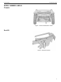
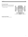
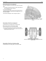
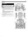
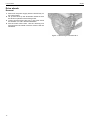
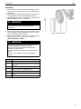
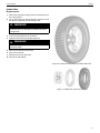
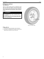
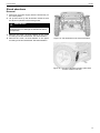
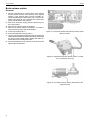
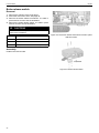
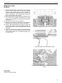
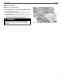
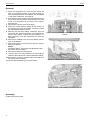
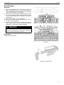
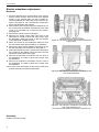
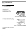
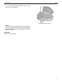
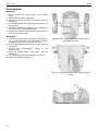
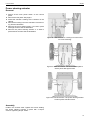
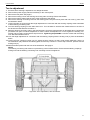
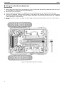
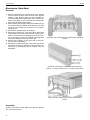
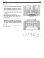
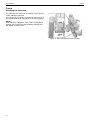
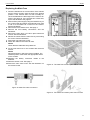
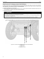
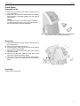
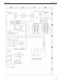
Service manual
X850
English
Introduction
The Service Manual is intended for technical personnel who maintain and
repair power wheelchairs. It is important that anyone who performs
maintenance and repairs described in this manual reads and understands
the content of this manual so that the work is performed professionally.
Always state the chassis number when contacting Permobil to ensure that
the correct information is provided.
Text
Produced and published by Permobil AB
Edition: Edition 2, 2015-09
Order no: 205214-UK-0
Permobil X850
How to contact Permobil
Permobil Benelux BV
De Beitel 11
6466 GZ Kerkrade
Netherlands
Tel:
+31 (0)45 564 54 80
Fax:
+31 (0)45 564 54 81
Email::
[email protected]
The Permobil Group’s Head Office
Permobil AB
Box 120
Tel:
861 23 Timrå
Sweden
+46 60 59 59 00
Fax:
+46 60 57 52 50
E-mail:
[email protected]
Permobil X850
Contents
CONTENTS
Serial Number labels .................................................................................................................................... 9
Repairs ......................................................................................................................................................... 11
Adjustments ................................................................................................................................................. 53
Troubleshooting .......................................................................................................................................... 55
Cabling Overview........................................................................................................................................ 57
Permobil X850
Serial Number labels
SERIAL NUMBER LABELS
Chassis
Figure 1. Chassis identification number.
Seat lift
Figure 2. Seat lift ID number.
9
Permobil X850
10
Serial Number labels
Permobil X850
Repairs
REPAIRS
Covers............................................................................................... 12
Batteries ........................................................................................... 16
Drive wheels .................................................................................... 18
Front wheels .................................................................................... 20
Inner tube ......................................................................................... 21
Filling tyres with air.......................................................................... 22
Shock absorbers ............................................................................. 23
Brake release cables ...................................................................... 24
Brake release switch....................................................................... 26
Magnetic brake ................................................................................ 27
Drive motor....................................................................................... 28
Fixed seat ......................................................................................... 30
Electric seat lift................................................................................. 31
Seat lift motor................................................................................... 33
Electric wheelbase adjustment ..................................................... 34
Front .................................................................................................. 35
Steering knuckle suspension and bearings................................. 36
Potentiometer .................................................................................. 38
Power steering actuator ................................................................. 39
Toe-in check..................................................................................... 40
Toe-in adjustment............................................................................ 41
Bushings in wheelbase adjustment .............................................. 42
Bushing and plastic guide .............................................................. 43
Electronics (Safe Gate) .................................................................. 44
Connection box................................................................................ 45
Fuses ................................................................................................ 46
Front lights........................................................................................ 49
Front indicators................................................................................ 50
Rear lights/indicators ...................................................................... 51
11
Permobil X850
Repairs
Covers
Removing the chassis covers
1. Chassis with electric seat lift: Place the wheelchair
on a level surface. Raise the seat to the highest position. If the seat lift does not work normally because
the batteries are discharged or the motor is defective,
see Manual raising/lowering, Page 31.
Chassis with a fixed seat: Remove the rear cover. It
is fixed with two knobs at the rear and one knob on
the left and right sides. Tip the seat forwards. See
Fixed seat, Page 30.
2. Switch off the power supply with the On/Off key on
the control panel.
3. Remove the front cover. This is fixed with two knobs
on the sides and two guide pins at the front. Lift the
cover up and forwards. Divide the cabling to the crush
protection at the contact on the cabling.
4. On a chassis with an electric seat lift, remove the rear
cover. This is fixed with the same knob as the front
cover and two knobs at the rear. Lift the cover up and
backwards.
NOTE!
If necessary, the rear cover can be removed without raising the seat.
Figure 3. The front cover is fixed with one knob on each
side and two guide pins at the front.
Figure 4. The rear cover is fixed with the same knob as
the front cover and two knobs at the rear.
Figure 5. Chassis covers.
Assembly of the chassis covers
Assembly the covers in the reverse order.
12
Permobil X850
Repairs
Removing the footplate
The foot plate is fitted with ten screws, three on the right
and left sides and four on the top of the foot plate. See
fig. 6.
1. Unscrew and remove the ten screws that hold the foot
plate in place. See fig. 6.
Figure 6. The foot plate’s cover is held in place with 10
screws.
Assembly of the footplate
Assemble the chassis cover in the reverse order.
13
Permobil X850
Repairs
Removing the front mudguard
The front mudguards are held in place with four screws
each.
1. Unscrew and remove the four screws that hold the
front mudguard in place. See fig. 7.
2. Lift the mudguard up.
To divide the light cabling, remove the foot plate. See Removing the footplate. Then divide the cabling at the contact on the cabling.
For removal of the lights, see Front lights, Page 49.
Figure 7. The front mudguard is held in place with 4
screws.
Assembly of the front mudguard
Assemble the front mudguard in the reverse order.
Removing the front’s bottom plate
The front’s bottom plate is held in place with six screws.
1. Unscrew and remove the eight screws that hold the
bottom plate in place. See 8.
Figure 8. The front’s bottom plate is held in place with
eight screws.
Assembly of the front’s bottom plate
Assemble the front’s bottom plate in the reverse order.
14
Permobil X850
Repairs
Removing the crush protection
The crush protection is held in place with two screws.
1. Place the wheelchair on a level surface. Raise the
seat to the highest position. If the seat lift does not
work normally because the batteries are discharged
or the motor is defective, see Manual raising/lowering, Page 31.
2. Switch off the power supply using the ON/OFF key on
the control panel and switch the automatic main fuse
to Off.
3. Remove the front chassis cover. This is fixed with two
knobs on the sides and two guide pins at the front. Lift
the cover up and forwards. Divide the cabling to the
crush protection at the contact on the cabling. See
Removing the chassis covers, Page 12.
4. Unscrew and remove the two screws that hold the
crush protection in place. See fig. 9.
5. Lift the crush protection up and forwards.
6. Remove the crush protection switch. This is held in
place with a nut. See fig. 10.
Figure 9. The crush protection cover is held in place on
the chassis’ front cover with two screws.
Figure 10. Crush protection with cover and sensor.
15
Permobil X850
Repairs
Batteries
L
WARNING!
Be careful when using metal objects when working
with batteries. A short-circuit can easily cause an
explosion. Always use safety gloves and safety
goggles.
Removal
1. Place the wheelchair on a level surface.
2. Switch off the power supply using the ON/OFF key on
the control panel and switch the automatic main fuse
to Off. It is accessible via a recess on the chassis.
See fig. 11.
NOTE!
Ensure that the power supply is switched off using
the ON/OFF key on the control panel before the automatic main fuse is switched to Off.
3. Remove the chassis covers. See Removing the chassis covers, Page 12.
Figure 11. Main fuse/battery isolator (On/Off)
4. Disconnect the battery connections. See fig. 12.
5. Loosen the four knobs that hold the batteries’ fixing
bars. See fig. 12.
6. Turn the battery bars backwards. Lift out the
batteries.
Figure 12. The batteries’ fixing bars and connections.
16
Permobil X850
Repairs
Assembly
1. Lift two new batteries into place. The battery poles
must face out from the centre of the chassis.
L
WARNING!
Be careful when using metal objects when working
with batteries. A short-circuit can easily cause an
explosion. Always use safety gloves and safety
goggles.
2. Fix the batteries in place with the two battery bars,
which are held in place with the four knobs. See fig.
12
3. Connect the battery connections. See fig. 12
4. Refit the chassis covers. See Assembly of the chassis covers, Page 12.
5. Switch the automatic main fuse to ON. It is accessible
via a recess on the chassis. See fig. 11.
17
Permobil X850
Repairs
Drive wheels
Removal
1. Switch off the power supply with the On/Off key on
the control panel.
2. Lift up and chock up the wheelchair chassis so that
the wheel in question is free of the ground.
3. Loosen and remove the hub cap 1, the screw 2 and
the washers 3, 4 and 5. See the illustration.
4. Pull the wheel off the axle. Use the removing tool
304103-99-0 if the wheel is hard to remove. See the
illustration.
Figure 13. Removing tool 304103-99-0.
18
Permobil X850
Repairs
Assembly
1. Check that the axle and rim are not damaged. If necessary, clean to remove dirt and rust. Replace damaged parts.
2. Check that the parallel key is properly located and is
not damaged. Fit a new parallel key if necessary.
3. Lubricate the axle with a thin layer of copper paste
(Würth 0893800x, Art. no.: 1820540).
L
WARNING!
The threads on the screw and in the screw hole
must not be lubricated. Clean the threads if
necessary.
4. Fit the wheel on the axle using just your hands. Check
that the wheel is fully located on the axle. If necessary, use a rubber mallet carefully.
5. Fit the four washers 3, 4 and 5 on the screw 2 and
tighten the wheel. Fit the hub cap 1. See fig. 14.
Tightening torque: 33 Nm.
L
Figure 14. Drive wheel.
WARNING!
Screws must only be used once. Once removed,
screws must therefore never be refitted.
No type of screw and washer other than those
stated here may be used.
No other type of lock coating or lock liquid may be
used.
Do not use an impact wrench for the tightening
torque.
Item
Description
1.
Hub cap
2.
Screw, ISO 4762 M8x35 10.9 Fe/Zn 5 C2 / Locking coat
DIN 267-28
3.
Shim washer DIN 988 8 A2 (DB 8x14x0.5 stainless)
4.
Washer, 8 Fe/Zn 5 C1 (TBRSB 8.4x26x5)
5.
Washer, PA6 (8.4x15x1.5 type F)
6.
Wheel
7.
Parallel key DIN 6885A 6x6x36
19
Permobil X850
Repairs
Front wheels
Removal
1. Switch off the power supply with the On/Off key on the control panel.
2. Lift up and chock up the wheelchair chassis so that the wheel in question is free of the ground.
L
CAUTION!
The wheelchair must not be lifted by the seat or seat lift as this can damage the wheelchair and its components.
3.
4.
5.
6.
Remove the hub cap 4.
Fold out the locking lip on the locking washer.
Unscrew and remove the locking nut from the axle.
Pull the wheel off the axle. Use the removing tool 304103-99-0 with the appropriate adapter if the wheel is hard to
remove.
Assembly
1. Check that the axle and rim are not damaged. If necessary, clean to remove dirt and rust. Replace damaged parts.
2. Fit the wheel (1) on the axle.
3. Fit the locking washer and locking nut onto the axle. Rotate the wheel clockwise while tightening the nut until the
wheel rotates a little less freely. Loosen the nut until the wheel rotates freely again and then fold back the appropriate wing on the locking washer to lock the nut into position.
4. Refit the hub cap.
Item
Description
1.
Wheel
2.
Locking washer, ISO 2982 12 (MB1 12x25x1)
3.
Locking nut, ISO 2982 M12 (KM1)
4.
Hub cap
Figure 15. Fitting the front wheel.
20
Permobil X850
Repairs
Inner tube
Replacement
1. Switch off the power supply with the On/Off key on
the control panel.
2. Lift up and chock up the wheelchair chassis so that
the wheel in question is free of the ground.
L
WARNING!
The wheelchair must not be lifted by the seat or
seat lift as this can damage the wheelchair and its
components.
3. If the tyre is pumped up, let out the air.
4. Take one side of the tyre off the wheel rim.
L
WARNING!
Do not use sharp tools when working with tyres
and inner tubes.
5.
6.
7.
8.
Remove the defective inner tube.
Fit a new inner tube.
Refit the tyre on the wheel rim.
Fill with air. See below.
Figure 16. Take one side of the tyre off the wheel rim.
Figure 17. Wheel rim, inner tube and tyre.
21
Permobil X850
Repairs
Filling tyres with air
Tyre pressure
Check at regular intervals that the wheelchair’s tyres
have the correct tyre pressure. The incorrect tyre pressure may mean lower stability and manoeuvrability and
result in abnormal wear and shorter range. Therefore,
check regularly that the tyre pressure is 200-250 kPa (22.5 bar).
L
WARNING!
The recommended tyre pressure for front and rear
tyres is 200-250 kPa (2-2.5 bar). Overfilling entails a
risk of explosion.
The incorrect tyre pressure may result in lower stability
and manoeuvrability. So check regularly that the tyres
have the correct pressure.
Figure 18. Filling valve.
Filling with air
1. Unscrew and remove the plastic cap on the valve.
2. Connect the compressed air nozzle to the valve and
adjust the tyre pressure to the correct level.
22
Permobil X850
Repairs
Shock absorbers
Removal
1. Switch off the power supply with the On/Off key on
the control panel.
2. Lift up and chock up the wheelchair chassis so that
the wheel in question is free of the ground.
L
WARNING!
The wheelchair must not be lifted by the seat or
seat lift as this can damage the wheelchair and its
components.
3. Remove the screw, nut and washers on the lower
mounting of the shock absorber. See the illustration.
4. Remove the screw, nut and washers on the upper
mounting of the shock absorber. See the illustration.
Figure 19. The wheelchair’s two shock absorbers.
Figure 20. The shock absorber is held in place with
screws, washers and nuts.
23
Permobil X850
Repairs
Brake release cables
Removal
1. Place the wheelchair on a level surface. If the chassis
has an electric seat lift, raise the seat to the highest
position. If the seat lift does not work normally because the batteries are discharged or the motor is defective, see page 22. If the chassis has a fixed seat,
tip the seat forwards. See page 22.
2. Switch off the power supply with the On/Off key on
the control panel.
3. Remove the chassis covers. See page 7.
4. Remove the brake release mechanism. It is held in
place with two screws. See the illustration.
5. Loosen the locking nut (1).
6. Screw the adjusting screw (2) fully in.
7. Loosen the cable at the magnetic brake by pulling the
cable sheath forwards and pass the cable out through
the groove of the cable holder. Detach the brake release cable from the magnetic brake.
8. Screw the adjusting screw (2) fully out and loosen the
cable at the release lever.
Figure 21. The brake release mechanism is held in place
with two screws.
Figure 22. Adjustment of brake release cables. Locking
nut (1). Adjusting screw (2)
Figure 23. The brake release cable’s attachment to the
magnetic brake
24
Permobil X850
Repairs
Assembly
1. First fit the cable at the release lever, then at the magnetic brake.
2. Adjust the cable sleeve length with the adjusting
screw (2) so that the cable is tensioned so that the
brake release switch is activated immediately before
the cable pulls the release shackle.
3. Check that the wheel cannot be turned before the
brake release switch has been activated.
4. Check that the wheel can be turned when the brake
release has been released with the release lever.
5. Tighten the locking nut (1).
6. Refit the brake release mechanism and the chassis
covers.
Figure 24. Brake release switch.
Figure 25. Brake release mechanism.
25
Permobil X850
Repairs
Brake release switch
Removal
1. Remove the chassis covers. See page 7.
2. Switch the main fuse to OFF. See page 36.
3. Remove the brake release mechanism. It is held in
place with two screws. See the illustration.
4. Remove the brake release switch. It is held in place
with two screws. See the illustration.
L
CAUTION!
If the switch is to be replaced, its connection cables
have to be resoldered.
Item
Description
1.
Switch, VK08N001A
2.
Screw, ISO 4017 M3x20 8.8 Fe/Zn 5 C1
3.
Washer, ISO 7089 3 200 HV Fe/Zn 5 C1(3.2x7x0.5)
Figure 26. The brake release mechanism is held in place
with two screws.
Assembly
Install in the reverse order.
Figure 27. Brake release switch
26
Permobil X850
Repairs
Magnetic brake
Removal
1. Place the wheelchair on a level surface. If the chassis
has an electric seat lift, raise the seat to the highest
position. If the seat lift does not work normally because the batteries are discharged or the motor is defective, see page 22. If the chassis has a fixed seat,
tip the seat forwards. See page 22.
2. Switch off the power supply using the ON/OFF key on
the control panel and switch the automatic main fuse
to Off. It is accessible via a recess on the chassis.
See page 36.
3. Remove the chassis covers. See page 7.
4. Remove the electrical connection of the magnetic
brake from the connection box. See the illustration.
5. Pull the cable sheath forwards and pass the cable out
through the groove of the cable holder. Detach the
brake release cable from the magnetic brake. See the
illustration.
6. Unscrew and remove the three screws that hold the
brake in place. See the illustration. Note the position
of the brake release arm for subsequent fitting. Remove the brake.
Figure 28. Magnetic brake’s electrical connection.
Figure 29. Detach the brake release cable.
Figure 30. The magnetic brake is held in place with three
screws.
Assembly
Install in the reverse order.
27
Permobil X850
Repairs
Drive motor
Removal
1. Place the wheelchair on a level surface. If the chassis
has an electric seat lift, raise the seat to the highest
position. If the seat lift does not work normally because the batteries are discharged or the motor is defective, see page 22. If the chassis has a fixed seat,
tip the seat forwards. See page 22.
2. Switch off the power supply using the ON/OFF key on
the control panel and switch the automatic main fuse
to Off. It is accessible via a recess on the chassis.
See the illustration.
3. Remove the chassis cover. See page 7.
4. Raise and chock up the relevant side of the
wheelchair.
Figure 31. Main fuse/battery isolator (On/Off).
Figure 32. Magnetic brake’s electrical connection.
28
Permobil X850
L
Repairs
CAUTION!
The wheelchair must not be lifted by the seat or
seat lift as this can damage the wheelchair and its
components.
5. Remove the rear wheel on the relevant side. See
page 12.
6. Remove the electrical connection of the magnetic
brake from the connection box. See the illustration.
7. Remove the two electrical connections of the drive
motor. They are located opposite each other on the
sides of the motor. See the illustration.
8. Remove the four screws that hold the drive motor’s
gear in place. See the illustration.
9. Lift the motor and gear up out of the chassis.
Assembly
Install in the reverse order.
Figure 33. Front electrical connection of the right drive
motor.
Figure 34. The drive motor is held in place with four
screws.
29
Permobil X850
Repairs
Fixed seat
Folding the seat
To be able to remove the chassis covers on a chassis
with a fixed seat, the seat’s rear mounting must be removed so that the seat can be folded forwards.
1. Remove the rear chassis cover. See page 7.
2. Using the tool supplied, remove the screw, washers
and nut that hold the seat in place at the rear. See the
illustration.
3. Carefully tilt the seat forwards.
Adjusting the seat height/angle
The height/angle of the seat is adjusted by fitting the seat
in one of the three sets of holes (1) front and rear.
Figure 35. Rear mounting of the seat.
Adjust the seat supports as well so that they are in contact with the chassis. Adjust the seat supports by fitting
them in one of the three sets of holes (2).
Figure 36. Fit the seat in one of the sets of holes (1). Fit
the seat supports in one of the sets of holes (2).
30
Permobil X850
Repairs
Electric seat lift
Manual raising/lowering
If the seat lift does not work normally because the batteries are discharged or the motor is defective, the seat
can be raised/lowered manually.
1. Switch off the power supply with the On/Off key on
the control panel.
2. Raise/lower the seat using the sleeve and ratchet
handle. See the illustration. Turn the screw clockwise
to raise the seat and anticlockwise to lower it.
L
WARNING!
Drills must not be used in connection with manual
operation of the seat lift. There is a risk of damage to
materials.
Figure 37. Manual raising/lowering of the seat using the
box spanner (13mm.) supplied.
31
Permobil X850
Repairs
Removal
1. Place the wheelchair on a level surface. Raise the
seat to the highest position. If the seat lift does not
work normally because the batteries are discharged
or the motor is defective, see page 22.
2. Switch off the power supply using the ON/OFF key on
the control panel and switch the automatic main fuse
to Off. It is accessible via a recess on the chassis.
See page 36.
3. Remove the chassis covers. See page 7.
4. Divide the control panel’s cabling at the contact on
the cabling on the rear of the seat. Loosen any cable
ties that hold the cabling in place.
5. Remove the seat lift’s cabling connection from the
connection box. See the illustration. If the chassis has
electric seat rotation, remove the seat rotation’s cabling connection from the connection box. See the
illustration.
6. Remove the cabling from the quick release mountings on the seat lift.
7. Remove the seat. It is held in place with two screws.
See the illustration.
NOTE!
The seat is heavy. Two people should therefore lift it.
Be careful with the cabling.
8. Remove the batteries. See page 10.
9. Remove the screw and locking nut (1) that hold the
seat lift in place at the rear. See the illustration below.
10. Remove the screws (2) on both sides of the seat lift at
the bottom of the mounting.
11. Lift the seat lift straight up out of the chassis.
Figure 38. Electrical connections of the seat lift and seat
rotation.
Figure 39. The seat is held in place with two screws.
Figure 40. Removing/installing the electric seat lift.
Assembly
Install in the reverse order.
32
Permobil X850
Repairs
Seat lift motor
Removal
1. Place the wheelchair on a level surface. Raise the
seat to the highest position. If the seat lift does not
work normally because the batteries are discharged
or the motor is defective, see page 22.
2. Switch off the power supply using the ON/OFF key on
the control panel and switch the automatic main fuse
to Off. It is accessible via a recess on the chassis.
See page 36.
3. Remove the chassis covers. See page 7.
4. Remove the seat lift motor’s cabling from the connection box. See the illustration.
5. Unscrew and remove the two screws that hold the
motor in place at the very rear of the seat lift. See the
illustration. Pull the motor straight backwards.
L
Figure 41. The seat lift motor’s electrical connection.
WARNING!
The seat lift motor must not be operated unless the
motor is properly screwed to the seat lift. Otherwise
there is a risk of damage to materials.
Assembly
Install in the reverse order.
Figure 42. The seat lift motor is held in place with two
screws.
Figure 43. Seat lift motor.
33
Permobil X850
Repairs
Electric wheelbase adjustment
Removal
1. Place the wheelchair on a level surface. If the chassis
has an electric seat lift, raise the seat to the highest
position. If the seat lift does not work normally because the batteries are discharged or the motor is defective, see page 22. If the chassis has a fixed seat,
tip the seat forwards. See page 22.
2. Switch off the power supply using the ON/OFF key on
the control panel and switch the automatic main fuse
to Off. It is accessible via a recess on the chassis.
See page 36.
3. Remove the chassis covers. See page 7.
4. Remove the bottom plate under the front of the
wheelchair. It is held in place with eight screws. See
the illustration. Raise and chock up the front wheels
of the wheelchair for better access.
5. Raise and chock up the wheelchair chassis so that
the rear wheels have approximately 5 cm clearance.
6. Remove the lower shock absorber mountings on the
left and right sides of the wheelchair. See page 15.
7. Divide the extension motor’s electrical connections at
the contacts on the cabling next to the motor. See the
illustration at the bottom of the page.
8. Remove the extension mechanism from the front of
the wheelchair. It is held in place with a screw. See
the illustration.
9. Remove the extension mechanism from the rear of
the wheelchair. It is held in place with a screw. See
the illustration.
10. Turn the motor downwards so that it turns freely and
pull the extension mechanism backwards.
Figure 44. The front’s bottom plate is held in place with
eight screws.
Figure 45. The extension mechanism’s mounting at the
front of the wheelchair
Figure 46. The extension mechanism’s mounting at the
rear of the wheelchair (1).
The extension mechanism’s electrical connection (2).
Assembly
Install in the reverse order.
34
Permobil X850
Repairs
Front
Removal
1. Switch off the power supply using the ON/OFF key on
the control panel and switch the automatic main fuse
to Off. It is accessible via a recess on the chassis.
See page 36.
2. Remove the foot plate. See page 8.
3. Remove the potentiometer’s cover plate. See the
illustration.
4. Divide the cabling for power steering and lights at the
contacts on the cabling and remove the potentiometer’s electrical connection at the contact on the
potentiometer.
5. Loosen the front’s bracket at the rear of the chassis.
For a chassis with electric wheelbase adjustment,
see page 25. For a chassis with manual wheelbase
adjustment, see the illustration to the right.
6. Remove the stop lug from the centre tube. It is held in
place with four screws. See the illustration. If necessary, remove one battery to allow better access. See
page 10.
Raise and chock up the chassis so that the front and
the front wheels are free of the ground. Pull the front
straight out from the chassis.
L
Figure 47. The potentiometer’s cover plate is held in
place with two screws (1).
The cabling is held in place with one screw (2).
WARNING!
The wheelchair must not be lifted by the seat or
seat lift as this can damage the wheelchair and its
components.
Assembly
Install in the reverse order. When refitting the stop lug,
glue the four screws with Loctite 628.
Figure 48. The front’s bracket on a chassis with manual
wheelbase adjustment.
Figure 49. The centre tube’s stop lug.
35
Permobil X850
Repairs
Steering knuckle suspension and
bearings
Removal
L
WARNING!
The wheelchair must not be lifted by the seat or seat lift
as this can damage the wheelchair and its
components.
1. Switch off the power supply with the On/Off key on
the control panel.
2. Raise and chock up the front.
3. Remove the front mudguard. See page 8.
4. Remove the front wheel. See page 13.
5. Remove the steering connecting rod. It is held in
place with one nut (2). See the illustration.
Figure 50. The steering connecting rod is held in place
with one nut.
6. Remove the screw, washer and the plastic plug fastener (1) of the steering connecting rod.
7. Remove the plastic plug from the top of the steering
coupling. See the illustration.
Figure 51. The steering knuckle is held in place with one
screw.
8. Remove the screw that holds the steering knuckle in
place. Then lift the steering knuckle straight up. See
the illustration.
36
Permobil X850
Repairs
9. Turn the steering knuckle around. Press out the
spring using a screwdriver.
Figure 52. Steering knuckle.
NOTE!
Be very careful when removing the spring so that the
two O-rings and the sliding bushing are not damaged.
10. Replace the ball bearing, sliding bushing and knuckle
spring as required.
Assembly
Install in the reverse order.
37
Permobil X850
Repairs
Potentiometer
Removal
1. Switch off the main power switch on the control
panel.
2. Remove the foot plate. See page 8.
3. Remove the potentiometer’s cover plate. See the
illustration.
4. Cut off the cable tie that holds the potentiometer’s cabling in place.
5. Remove the electrical connection of the potentiometer at the contact on the potentiometer.
6. Remove the potentiometer. It is held in place with two
screws. See the illustration.
Assembly
1. Grease the O-ring. Adjust the bevel of the shaft journal so that it matches the potentiometer. Carefully
press the potentiometer in place on the shaft.
2. Fit the potentiometer with the two screws. See the
illustration.
3. Connect the potentiometer’s cabling to the
potentiometer.
4. Refit the potentiometer’s cover plate. See the
illustration.
5. Fix the cabling to the cover plate using a cable tie.
6. Refit the foot plate. See page 8.
Figure 53. The potentiometer’s cover plate is held in
place with two screws.
Figure 54. The potentiometer is held in place with two
screws.
Figure 55. Installation of the potentiometer.
38
Permobil X850
Repairs
Power steering actuator
Removal
1. Switch off the main power switch on the control
panel.
2. Remove the foot plate. See page 8.
3. Divide the actuator’s cabling at the contacts on the
cabling.
4. Remove the locking nut on the actuator’s front mounting. See the illustration.
5. Remove the front’s bottom plate. It is held in place
with eight screws. See the illustration.
6. Remove the power steering actuator. It is held in
place with two screws. See the illustration.
Figure 56. View from above. Locking nut on the actuator’s front mounting.
Figure 57. View from below. The front’s bottom plate is
held in place with eight screws.
Figure 58. View from below. The power steering actuator
is held in place with two screws.
Assembly
Install in the reverse order. Tighten the screws holding
the power steering actuator in place with a torque
wrench. Tightening torque: 24Nm.
39
Permobil X850
Repairs
Toe-in check
Ensure that the steering is adjusted so it is straight forwards.
The distance between the centre line of the front tyres must be 2-4 mm less on the front of the tyres than on the rear.
Figure 59. View from above. Locking nuts on the steering connecting rods’ mountings.
40
Permobil X850
Repairs
Toe-in adjustment
1.
2.
3.
4.
5.
6.
Ensure that the steering is adjusted so it is straight forwards.
Switch off the power supply with the On/Off key on the control panel.
Remove the foot plate. See page 8.
Remove the locking nuts on the steering connecting rods’ mountings. See the illustration.
Remove the bottom plate under the front of the wheelchair. See page 8.
Remove the steering connecting rods from the steering plate. They are held in place with one screw (1) each. See
the illustration below.
7. Loosen the stop nut (2) that locks the length adjustment in connection with the steering coupling at the extremities
of both steering connecting rods.
8. Turn the steering coupling on both sides half a turn. Turn clockwise to increase the measurement on the front of
the wheels and anticlockwise to reduce it.
9. Refit the steering connecting rods in the steering plate. Check the measurement as described above. Repeat the
procedure from point 4 until the adjustment is correct. When the adjustment is correct, tighten the steering connecting rods’ mounting screws with a torque wrench. Tightening torque:24Nm. Lock the screws with the locking
nuts. See the illustration above.
10. Lock the length adjustment in connection with the steering coupling with the locking nuts (2). See the illustration
below.
11. Loosen the stop cushions’ locking nuts (3). Adjust the stop cushions so that, at full joystick deflection, there is a
few millimetres’ play between the steering plate and the stop cushions. Lock the stop cushions’ position with the
locking nuts (3).
12. Refit the bottom plate under the front of the wheelchair. See page 8.
NOTE!
The steering connecting rods must be in place during control measurement. Ensure that the steering couplings’
locking nuts and the steering connecting rods’ mounting screws are tightened.
Figure 60. Toe-in adjustment, view from below.
41
Permobil X850
Repairs
Bushings in wheelbase adjustment
Replacement
1. Switch off the power supply using the ON/OFF key on the control panel and switch the automatic main fuse to Off.
It is accessible via a recess on the chassis. See page 36.
2. Remove the front. See page 27.
3. Use Permobil’s special tool (Art. no.: INR8205) or remove the bushings from the chassis in some other way.
4. Press in new bushings. Press the inner bushing in to the edge of the recess for the stop lug. The outer bushing
should be level with the front edge of the tube. See the illustration. Use Permobil’s special tool (Art. no.: INR8205)
or fit the bushings in some other way.
5. Refit the front in the chassis. See page 27. When fitting the stop lug, glue the threads of the four screws with Loctite 628.
Figure 61. Wheelbase adjustment bushings.
42
Permobil X850
Repairs
Bushing and plastic guide
Replacement
1. Switch off the power supply using the ON/OFF key on
the control panel and switch the automatic main fuse
to Off. It is accessible via a recess on the chassis.
See the illustration.
2. Remove the chassis covers. See page 7.
3. Raise and chock up the wheelchair chassis so that
the rear wheels are free of the ground.
L
WARNING!
The wheelchair must not be lifted by the seat or
seat lift as this can damage the wheelchair and its
components.
4. Remove the shock absorbers’ lower mountings. See
page 15.
5. Remove the screw that holds the swivel arm at the
front on the right or left side.
6. Replace the bushing in the swivel arm on each side
by pressing out the old one and fitting a new one. Lubricate the bushing with a thin layer of grease.
7. Drill out the pop rivet that holds the plastic guide in
place.
8. Fit a new plastic guide with a pop rivet.
9. Refit the swivel arm on the chassis.
10. Refit the shock absorbers to the swivel arm.
11. Refit the chassis covers. See page 7.
Figure 62. Main fuse/battery isolator (On/Off).
Figure 63. The swivel arm is held in place with one screw
on each side of the chassis.
Figure 64. The plastic guide is held in place with one pop
rivet on the inside of the swivel arm.
43
Permobil X850
Repairs
Electronics (Safe Gate)
Removal
1. Place the wheelchair on a level surface. If the chassis
has an electric seat lift, raise the seat to the highest
position. If the seat lift does not work normally because the batteries are discharged or the motor is defective, see page 22. If the chassis has a fixed seat,
tip the seat forwards. See page 22.
2. Switch off the power supply using the ON/OFF key on
the control panel and switch the automatic main fuse
to Off. It is accessible via a recess on the chassis.
See page 36.
3. Remove the chassis covers. See page 7.
4. Remove the electronics. They are held in place with
three screws on the rear of the chassis. See the illustration. Lift the electronics straight up out of the chassis. If necessary, loosen the cabling mountings and
and some cabling from the connection box.
5. Remove the contacts on the right side of the electronics. See the illustration.
6. Remove the rubber protection on the left side of the
electronics by pulling it straight out. Remove the contact block by unscrewing the six screws. See the
illustration.
Figure 65. The electronics are is held in place with three
screws.
Figure 66. Connections on the right side of the electronics. 1: To the connection box. 2: To the control panel.
Figure 67. The contact block is held in place with 6
screws.
Assembly
Install in the reverse order. Make sure that all contacts
are connected correctly.
44
Permobil X850
Repairs
Connection box
Removal
1. Place the wheelchair on a level surface. If the chassis
has an electric seat lift, raise the seat to the highest
position. If the seat lift does not work normally because the batteries are discharged or the motor is defective, see page 22. If the chassis has a fixed seat,
tip the seat forwards. See page 22.
2. Switch off the power supply using the ON/OFF key on
the control panel and switch the automatic main fuse
to Off. It is accessible via a recess on the chassis.
See page 36.
3. Remove the chassis covers. See page 7.
4. Remove the electronics. See the previous page.
5. Remove all electrical connections from the connection box and release the cabling from the quick-release mountings.
6. If the chassis has electric wheelbase adjustment, divide the wheelbase adjustment’s electrical connection at the contact on the cabling. See page 25.
7. Remove the connection box. It is held in place with
two screws on the rear of the chassis. See the illustration. Lift the connection box straight up out of the
chassis.
Figure 68. 1: Connection box.
2: Electronics.
Assembly
Install in the reverse order. Make sure that all contacts
are connected correctly.
Figure 69. The connection box is held in place with two
screws
Figure 70. The connection box’s electrical connections.
45
Permobil X850
Repairs
Fuses
Resetting the main fuse
The main fuse also functions as a battery isolator but it is
usually called the main fuse.
It is not normally necessary to replace the main fuse as it
is automatic and can be reset when it has been triggered.
NOTE!
If the main fuse is triggered, there is often a major electrical fault. The cause of the fault should be checked carefully before the fuse is reset.
Figure 71. Main fuse/battery isolator (On/Off).
46
Permobil X850
Repairs
Replacing the Main Fuse
1. Place the wheelchair on a level surface. If the chassis
has an electric seat lift, raise the seat to the highest
position. If the seat lift does not work normally because the batteries are discharged or the motor is defective, see page 22. If the chassis has a fixed seat,
tip the seat forwards. See page 22.
2. Switch off the power supply using the ON/OFF key on
the control panel and switch the automatic main fuse
to Off. It is accessible via a recess on the chassis.
See the illustration.
3. Remove the front chassis cover. See page 7.
4. Remove the front battery connections. See the
illustration.
5. Remove the main fuse. It is held in place with three
screws. See the illustration.
6. Detach the cables from the main fuse by unscrewing
the screws. See the illustration.
7. Switch the new main fuse to OFF.
8. Attach the cables to the new main fuse.
NOTE!
Check that the cables are firmly attached.
9. Fit the new main fuse on the chassis with the three
screws.
NOTE!
Note the direction in which the fuse is installed. The
ON/OFF position must match the appropriate sticker
on the chassis.
10. Reattach the battery connection cables to the
batteries.
11. Refit the chassis cover. See page 7.
12. Switch the main fuse to ON. See the illustration on
the previous page.
Figure 72. Front battery connections.
Figure 73. The main fuse is held in place with 3 screws
Figure 75. Main fuse cable connection.
Figure 74. The main fuse is held in place with 3 screws.
47
Permobil X850
Repairs
Replacing fuses for charging, actuator, lights/indicators
Fuses for the actuator (15 A) and lights/indicators (7.5 A) are located at the lower edge of the rear of the wheelchair
(connection box). The charging fuse (20 A) is located between the right drive motor and the chassis. All these fuses
are accessible from the rear of the wheelchair. See the illustration.
1. Place the wheelchair on a level surface.
2. Switch off the power supply using the ON/OFF key on the control panel and switch the automatic main fuse to Off.
It is accessible via a recess on the chassis. See the illustration.
3. Replace the blown fuse.
L
WARNING!
Always switch off the power supply to the control panel before changing the charging fuse. The battery charger
must not be connected when the charging fuse is changed.
If the charging fuse is triggered, there may be problems or faults with batteries, the charger/charging cables or
the wheelchair’s charging socket.
The cause of the charging fuse being triggered should be checked carefully before the fuse is changed.
Figure 76. The fuses are accessible from the rear of the wheelchair.
1. Actuator 15 A
2. Lights 7.5 A
3. Charging fuse 20 A
48
Permobil X850
Repairs
Front lights
Changing a bulb
1. Switch off the power supply with the On/Off key on
the control panel.
2. Remove the ring that surrounds the light by carefully
levering with a screwdriver between the ring and the
light housing.
NOTE!
For reasons of space, the bulb is always installed in
the light housing so that its connection cables are at
the top of the socket. See the illustration.
Figure 77. Bulb replacement. Always fit the bulb with the
bulb socket’s cable connections at the top.
Removing
1. Switch off the power supply with the On/Off key on
the control panel.
2. Remove the foot plate. See page 8.
3. Divide the light’s cabling at the contact on the cabling
on the inside of the foot plate.
4. Remove the screws that hold the cable trunk. See the
illustration below.
5. Remove the two cable holders on the front of the
wheelchair. See the illustration below.
6. Remove the three screws that hold the light in place.
These are on the top of the light. See the illustration
below.
Figure 78. Front light.
Assembly
Install in the reverse order.
49
Permobil X850
Repairs
Front indicators
Removal
1. Switch off the power supply with the On/Off key on
the control panel.
2. Remove the foot plate. See page 8.
3. Divide the indicator light’s cabling at the contact on
the cabling. This is located on the inside of the foot
plate.
4. Remove the cabling mounting. See the illustration.
5. The light is held in place with tape that is adhesive on
both sides. Use a screwdriver or similar to press the
light out from the inside.
Assembly
Install in the reverse order.
50
Figure 79. For removal, the cable mounting must be
removed.
Permobil X850
Repairs
Rear lights/indicators
Removal
1. Switch off the power supply with the On/Off key on
the control panel.
2. Remove the rear chassis cover. See page 7.
3. Divide the light’s cabling at the contact on the cabling.
This is on the inside of the rear bank of lights.
4. Remove the two screws that hold the lights in place.
See the illustration.
Figure 80. The cabling for the rear indicators and lights
are divided at the contacts on the cabling.
Figure 81. The backlights are two screws.
Assembly
Install in the reverse order.
51
Permobil X850
52
Repairs
Permobil X850
Adjustments
ADJUSTMENTS
Manual wheelbase adjustment ..................................................... 54
53
Permobil X850
Adjustments
Manual wheelbase adjustment
Adjustment
On delivery, the wheelchair is always transported adjusted to the minimum length. When it has been unpacked, it must be adjusted to the correct length. The
length is adjusted using the adjusting rod at the rear.
1. Remove the screw and nut from the adjusting rod.
See the illustration.
2. Adjust to the desired distance between the seat and
the foot plate. Choose between seven different
lengths. See the table below.
3. Fit the adjusting rod with the screw and nut in the desired position.
The wheelbase can be adjusted to seven different fixed
positions. On delivery, hole “G” in the adjusting rod always matches hole “G” in the chassis, i. e. the shortest
length. See the example below. The lengths below are
the c-c dimensions between the front and rear wheels.
Figure 82. Manual wheelbase adjustment.
Settings:
A to A
1015 mm.
B to B
980 mm.
C to C
945 mm.
D to D
910 mm.
E to E
885 mm.
F to F
850 mm.
G to G
815 mm.
Figure 83. Manual wheelbase adjustment.
54
Permobil X850
Troubleshooting
TROUBLESHOOTING
Troubleshooting guide .................................................................... 56
55
Permobil X850
Troubleshooting
Troubleshooting guide
The following troubleshooting guide describes a number of faults and events which may occur when you use your
wheelchair, together with suggested remedies. Note that this guide cannot describe all the problems and events which
may occur and you should always contact your service contact or Permobil in case of doubt.
EVENT
Wheelchair cannot be started.
POSSIBLE CAUSE
REMEDY
Batteries discharged.
Charge the batteries.
Main fuse switched to OFF position after, for
example, battery replacement.
Reset the main fuse. See page 46
Main fuse triggered.
See page 46
Battery charger connected.
Stop charging and disconnect the charging
cable from the wheelchair’s charging socket.
Brake release activated.
Reset the brake release.
Wheelchair locked with the security key.
Unlock the wheelchair.
Seat rotation activated.
Return the seat position to the drive position.
Battery voltage indicator on the control panel
flashes at 2.5 second intervals and the wheelchair cannot be driven.
Electronics’ power saving position is
activated.
Switch off and switch on the power using the
start key on the control panel.
Battery voltage indicator on the control panel
flashes quickly and the wheelchair cannot be
driven.
Electronics fault.
Contact service.
Wheelchair stops while being driven.
Main fuse triggered.
See page 46
Wheelchair can only be driven at reduced
speed. Applies to wheelchairs with an electric
seat lift.
Seat lift or seat angle raised too high.
Lower the seat lift.
Wheelchair cannot be charged.
Main fuse switched to OFF position after, for
example, battery replacement.
Reset the main fuse. See page 46
Charging fuse triggered, for example, on account of a fault in the batteries, charger,
charging cables, or charging socket.
Check possible causes carefully before
changing the charging fuse. See page46
Wheelchair cannot be driven.
56
Permobil X850
Cabling Overview
CABLING OVERVIEW
Chassis......................................................................................................................................................... 58
57
Permobil X850
Chassis
58
Cabling Overview
Permobil X850
Cabling Overview
59
Permobil X850
INDEX
B
Batteries.....................................16
Brake release cables ...................24
Brake release switch ...................26
Bushing and plastic guide ............43
Bushings in wheelbase
adjustment ................................42
Index
T
Toe-in adjustment........................41
Toe-in check ...............................40
Troubleshooting guide .................56
Tyre pressure — Filling with air.....22
C
Connection box ...........................45
Covers .......................................12
D
Drive motor.................................28
Drive wheels ...............................18
E
Electric seat lift............................31
Electric wheelbase adjustment .....34
Electronics (Safe Gate)................44
F
Fixed seat...................................30
Front ..........................................35
Front indicators ...........................50
Front lights..................................49
Front wheels ...............................20
Fuses.........................................46
I
Inner tube ...................................21
M
Magnetic brake ...........................27
Manual wheelbase adjustment .....54
P
Potentiometer .............................38
Power steering actuator ...............39
R
Rear lights/indicators ...................51
S
Seat lift motor..............................33
Shock absorbers .........................23
Steering knuckle suspension
and bearings .............................36
60
(dD0I1I|S TVXz
205214-UK-0
A