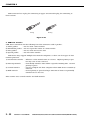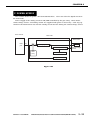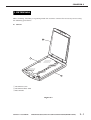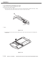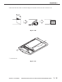
1
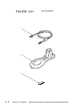
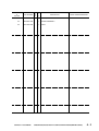
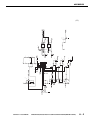
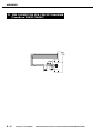
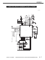
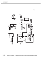
SERVICE MANUAL REVISION 0 JUNE 2000 COPYRIGHT 2000 CANON INC. JY8-1317-00Z CANOSCAN N650U/N656U/N1220U REV.0 JUNE 2000 PRINTED IN JAPAN (IMPRIME AU JAPON) COPYRIGHT © 2000 CANON INC. Printed in Japan Imprimè au Japon Use of this manual should be strictly supervised to avoid disclosure of confidential information. COPYRIGHT 2000 CANON INC. CANOSCAN N650U/N656U/N1220U REV.0 JUNE 2000 PRINTED IN JAPAN (IMPRIME AU JAPON) LIST OF SERIAL NUMBER CanoScan N650U CanoScan N656U CanoScan N1220U COPYRIGHT 2000 CANON INC. F91-4611-200 F91-4631-200 F91-4641-200 F91-4661-200 F91-4671-200 F91-4681-200 F91-4691-200 F91-4612-200 F91-4622-200 F91-4632-200 F91-4642-200 F91-4662-200 F91-4672-200 F91-4682-200 F91-4692-200 F91-4712-200 F91-4722-200 F91-4732-200 F91-4742-200 F91-4762-200 F91-4772-200 F91-4782-200 F91-4792-200 AZJ000001CZJ000001DZJ000001FZJ000001LZJ000001JZJ000001KZJ000001AZK000001MZK000001CZK000001DZK000001FZK000001LZK000001JZK000001KZK000001AZL000001MZL000001CZL000001DZL000001FZL000001LZL000001JZL000001KZL000001- CANOSCAN N650U/N656U/N1220U REV.0 JUNE 2000 PRINTED IN JAPAN (IMPRIME AU JAPON) PREFACE This service manual contains the basic information necessary for servicing the N650U/N656U/ N1220U image scanners. The service manual consists of the following chapters. Chapter 1: General Descriptions Features, specifications, exterior features, installation, customer’s daily maintenance Chapter 2: Operation and Timing Basic operation, optical system, image processing system, control system, power supply Chapter 3: Mechanical System Externals, drive system, optical system, electrical system Chapter 4: Maintenance and Servicing Periodical replacement parts, consumable parts durability, periodical servicing, special tools, solvents and lubricants Chapter 5: Troubleshooting Introduction, troubleshooting, location of electrical parts, canon scanner test Chapter 6: Parts Catalog Appendix: General Circuit Diagram, Main PCB Circuit Diagram, USB Connector PCB Circuit Diagram The information in this service manual is subject to change as the product is improved. All relevant information in such cases will be provided by the service information bulletins. A thorough understanding of the N650U/N656U/N1220U, based on the service manual and service information bulletins, is vital to the serviceman in maintaining the product quality and performance, and in locating and repairing the cause of malfunctions. COPYRIGHT 2000 CANON INC. CANOSCAN N650U/N656U/N1220U REV.0 JUNE 2000 PRINTED IN JAPAN (IMPRIME AU JAPON) CONTENTS CHAPTER 1 : GENERAL DESCRIPTIONS I. FEATURES ................................ 1-1 A. Preface ................................ 1-5 II. SPECIFICATIONS ...................... 1-2 B. Installation ......................... 1-6 III. EXTERIOR FEATURES .............. 1-4 C. Connecting to the Host Computer A. Front View .......................... 1-4 ........................................... 1-7 B. Rear View ............................ 1-4 D. Scanning a Document ......... 1-8 IV. INSTALLATION .......................... 1-5 V. CUSTOMER’S DAILY MAINTENANCE ........................................... 1-9 CHAPTER 2 : OPERATION AND TIMING I. D. Drive Motor Control Circuit BASIC OPERATION .................... 2-1 A. Functions ............................ 2-1 ......................................... 2-16 B. Outline of Electrical System 2-2 III. IMAGE PROCESSING SYSTEM . 2-17 C. Main PCB Input and Output 2-3 A. Outline .............................. 2-17 D. Basic Sequences .................. 2-4 B. Image Processing Functions II. OPTICAL SYSTEM ................... 2-11 ......................................... 2-18 A. Outline .............................. 2-11 IV. CONTROL SYSTEM .................. 2-20 B. Document Scanning Sequence . A. Outline .............................. 2-20 ......................................... 2-12 B. Outline of USB .................. 2-21 C. Contact Image Sensor ....... 2-13 V. POWER SUPPLY ...................... 2-23 CHAPTER 3 : MECHANICAL SYSTEM I. EXTERNALS .............................. 3-1 III. OPTICAL SYSTEM ..................... 3-9 A. Covers ................................. 3-1 A. Contact Image Sensor ......... 3-9 II. DRIVE SYSTEM ......................... 3-5 IV. ELECTRICAL SYSTEM ............. 3-11 A. Drive Unit ........................... 3-5 A. USB Connector PCB ........... 3-11 B. Drive Wire ........................... 3-8 B. Flat Cable .......................... 3-13 COPYRIGHT 2000 CANON INC. CANOSCAN N650U/N656U/N1220U REV.0 JUNE 2000 PRINTED IN JAPAN (IMPRIME AU JAPON) CHAPTER 4 : MAINTENANCE AND SERVICING I. PERIODICAL REPLACEMENT PARTS III. PERIODICAL SERVICING ........... 4-1 ........................................... 4-1 IV. SPECIAL TOOLS ........................ 4-1 II. CONSUMABLE PARTS DURABILITY . V. SOLVENTS AND LUBRICANTS .... 4-1 ........................................... 4-1 CHAPTER 5 : TROUBLESHOOTING I. INTRODUCTION ........................ 5-1 III. LOCATION OF ELECTRICAL PARTS A. Initial Check ....................... 5-1 ........................................... 5-4 B. Others ................................. 5-1 IV. CANON SCANNER TEST ............. 5-5 II. TROUBLESHOOTING ................. 5-2 A. Outline ................................ 5-5 A. Troubleshooting Image Defects B. How To Use Canon Scanner Test ........................................... 5-2 ........................................... 5-5 B. Troubleshooting Malfunctions ........................................... 5-3 CHAPTER 6 : PARTS CATALOG FIGURE U01 ACCESSORY ......... 6-2 FIGURE U11 N656U ........................ 6-6 FIGURE U10 N650U .................. 6-4 FIGURE U20 N1220U ...................... 6-8 APPENDIX I. GENERAL CIRCUIT DIAGRAM IV. USB CONNECTOR PCB CIRCUIT DIAGRAM (CanoScan N650U/N656U) (CanoScan N650U/656U) ........... A-1 ........................................... A-6 II. GENERAL CIRCUIT DIAGRAM (CanoScan N1220U) ................... A-2 III. MAIN PCB CIRCUIT DIAGRAM (CanoScan N650U/N656U) ......... A-3 V. MAIN PCB CIRCUIT DIAGRAM (CanoScan N1220U) ................... A-7 VI. USB CONNECTOR PCB CIRCUIT DIAGRAM (CanoScan N1220U) . A-10 COPYRIGHT 2000 CANON INC. CANOSCAN N650U/N656U/N1220U REV.0 JUNE 2000 PRINTED IN JAPAN (IMPRIME AU JAPON) CHAPTER 1 GENERAL DESCRIPTIONS FEATURES ................................ 1-1 A. Preface ................................ 1-5 II. SPECIFICATIONS ....................... 1-2 B. Installation ......................... 1-6 III. EXTERIOR FEATURES ............... 1-4 C. Connecting to the Host Computer I. A. Front View .......................... 1-4 ........................................... 1-7 B. Rear View ............................ 1-4 D. Scanning a Document .......... 1-8 IV. INSTALLATION .......................... 1-5 V. CUSTOMER’S DAILY MAINTENANCE ........................................... 1-9 COPYRIGHT 2000 CANON INC. CANOSCAN N650U/N656U/N1220U REV.0 JUNE 2000 PRINTED IN JAPAN (IMPRIME AU JAPON) CHAPTER 1 I. FEATURES CanoScan N650U/N656U with 600 x 1200 dpi resolution, CanoScan N1220U with 1200 x 2400 dpi resolution are flatbed image scanners incorporating the following features. 1. High gradation and high image quality are achieved by employing a highly sensitive contact image sensor with LIDE (LED Indirect Exposure) technology for the scanning unit, and by reading each RGB color by 14 bits and outputting by 8 bits. 2. The scanner is a small size of 256.0(W) x 372.5(D) x 34.0(H) mm, and a light weight of 1.5 kg by using a downsized scanning unit. 3. The scanner can easily be connected to the host computer through a USB interface. 4. Double hinge structure (Z-lid) enables the document cover to hold a thick document. 5. The scanner can be placed vertically to scan by using an optional stand. 6. The scanner draws its power from USB port on the host computer requiring no AC adapter. COPYRIGHT 2000 CANON INC. CANOSCAN N650U/N656U/N1220U REV.0 JUNE 2000 PRINTED IN JAPAN (IMPRIME AU JAPON) 1-1 CHAPTER 1 II. SPECIFICATIONS CanoScan N650U/N656U MAIN UNIT · Type : Flat bed image scanner READING UNIT · Image sensor · Light source · Max. document size · Image output · Resolution · Scan time : : : : : : INTERFACE · Interface : USB 1.1 (B plug) x 1 OTHERS · Operating environment · Power consumption · Dimensions · Weight 1-2 COPYRIGHT 2000 CANON INC. 5104 pixels contact image sensor LED indirect exposure (RGB each) A4 or Letter (216 x 297 mm) RGB 8 bits per channel (input 14 bits) 600 x 1200 dpi 112 sec. (color, A4, 600 dpi) 37 sec. (grayscale, A4, 600 dpi) 16 sec. (preview) : Temperature range, 5 to 35˚C Humidity range, 10 to 90% Air pressure range, 613 to 1013 hPa : 2.5W (during operation) : 256.0(W) x 372.5(D) x 34.0(H) mm : 1.4 kg CANOSCAN N650U/N656U/N1220U REV.0 JUNE 2000 PRINTED IN JAPAN (IMPRIME AU JAPON) CHAPTER 1 CanoScan N1220U MAIN UNIT · Type : Flat bed image scanner READING UNIT · Image sensor · Light source · Max. document size · Image output · Resolution · Scan time : : : : : : INTERFACE · Interface : USB 1.1 (B plug) x 1 OTHERS · Operating environment · Power consumption · Dimensions · Weight 10208 pixels contact image sensor LED indirect exposure (RGB each) A4 or Letter (216 x 297 mm) RGB 8 bits per channel (input 14 bits) 1200 x 2400 dpi 449 sec. (color, A4, 1200 dpi) 149 sec. (grayscale, A4, 1200 dpi) 16 sec. (preview) : Temperature range, 5 to 35˚C Humidity range, 10 to 90% Air pressure range, 613 to 1013 hPa : 2.5W (during operation) : 256.0(W) x 372.5(D) x 34.0(H) mm : 1.4 kg Specifications are subject to change with product improvement. COPYRIGHT 2000 CANON INC. CANOSCAN N650U/N656U/N1220U REV.0 JUNE 2000 PRINTED IN JAPAN (IMPRIME AU JAPON) 1-3 CHAPTER 1 III. EXTERIOR FEATURES A. Front View 1 A4 2 LTR B5 3 q w e r t Document Cover Document Glass Alignment Mark Start Button Carriage Lock 4 B5 A4 LTR 5 Figure 1-1 B. Rear View q USB Port 1 Figure 1-2 1-4 COPYRIGHT 2000 CANON INC. CANOSCAN N650U/N656U/N1220U REV.0 JUNE 2000 PRINTED IN JAPAN (IMPRIME AU JAPON) CHAPTER 1 IV. INSTALLATION A. Preface The following installation conditions are required. 1. Ambient temperature should be between 5˚C and 35˚C, and humidity between 10% and 90%. Avoid locations near water faucets, boilers, humidifiers, or refrigerators. 2. Avoid locations subject to open flame, dust, or direct sunlight. If it is installed near a window, hang a curtain to block direct sunlight. 3. The room should be well ventilated. 4. Install on a sturdy and level desk, etc. 5. Moving a scanner from a cold place to a warm place can cause condensation on the metal parts, resulting in a faulty operation. Give the scanner at least one hour to adjust to the room temperature before unpacking. COPYRIGHT 2000 CANON INC. CANOSCAN N650U/N656U/N1220U REV.0 JUNE 2000 PRINTED IN JAPAN (IMPRIME AU JAPON) 1-5 CHAPTER 1 B. Installation 1. Unlocking the carriage lock The scanner is shipped with the scanning unit locked by the carriage lock to prevent damage during transport. Unlock the scanning unit to use the scanner. 1) Turn the scanner over. Figure 1-3 2) Push the carriage lock to the unlock mark position. 1 q Carriage Lock Figure 1-4 3) Return the scanner to its standard position. Note: Always lock the scanning unit during transport. 1-6 COPYRIGHT 2000 CANON INC. CANOSCAN N650U/N656U/N1220U REV.0 JUNE 2000 PRINTED IN JAPAN (IMPRIME AU JAPON) CHAPTER 1 C. Connecting to the Host Computer The scanner is connected to the USB port on the host computer using a supplied USB cable. Refer to "Getting Started" for details. For connecting/disconnecting the host computer's cables, refer to the manual supplied with the host computer. 1) Connect the flat connector (A plug) of the USB cable to the USB port on the host computer. 2) Connect the square connector (B plug) of the USB cable to the USB port on the scanner. 1 2 q USB Port w USB Cable Figure 1-5 COPYRIGHT 2000 CANON INC. CANOSCAN N650U/N656U/N1220U REV.0 JUNE 2000 PRINTED IN JAPAN (IMPRIME AU JAPON) 1-7 CHAPTER 1 D. Scanning a Document 1) Open the document cover. 2) Place a document on the document glass, orienting the image face down and aligning its top edge with the alignment mark. A4 LTR B5 1 34 12 B5 A4 LTR q Alignment Mark Figure 1-6 3) Close the document cover, caring not to dislodge the document. 4) Send the "SCAN" command from the host computer to scan. 1-8 COPYRIGHT 2000 CANON INC. CANOSCAN N650U/N656U/N1220U REV.0 JUNE 2000 PRINTED IN JAPAN (IMPRIME AU JAPON) CHAPTER 1 V. CUSTOMER'S DAILY MAINTENANCE Dirt on a document glass or a document cover may cause an unclear image or lines on an image. Clean the document glass and the document cover using the following procedures. 1) Disconnect the USB cable from the scanner. 2) Wipe the dirt or dust off the document cover with a soft clean cloth dampened with water and well wrung, then thoroughly wipe water off with a dry cloth. 3) Wipe the document glass with a dry cloth caring not to leave wiper marks. COPYRIGHT 2000 CANON INC. CANOSCAN N650U/N656U/N1220U REV.0 JUNE 2000 PRINTED IN JAPAN (IMPRIME AU JAPON) 1-9 CHAPTER 2 OPERATION AND TIMING I. D. Drive Motor Control Circuit BASIC OPERATION .................... 2-1 A. Functions ............................ 2-1 ......................................... 2-16 B. Outline of Electrical System 2-2 III. IMAGE PROCESSING SYSTEM . 2-17 C. Main PCB Input and Output . 2-3 A. Outline .............................. 2-17 D. Basic Sequences ................. 2-4 B. Image Processing Functions ..... II. OPTICAL SYSTEM ................... 2-11 ......................................... 2-18 A. Outline .............................. 2-11 IV. CONTROL SYSTEM .................. 2-20 B. Document Scanning Sequence .. A. Outline .............................. 2-20 ......................................... 2-12 B. Outline of USB ................... 2-21 C. Contact Image Sensor ....... 2-13 COPYRIGHT 2000 CANON INC. V. POWER SUPPLY ....................... 2-23 CANOSCAN N650U/N656U/N1220U REV.0 JUNE 2000 PRINTED IN JAPAN (IMPRIME AU JAPON) CHAPTER 2 I. BASIC OPERATION A. Functions The scanner functions are divided into the three main blocks of optical system, image processing system, and control system. Contact image sensor Host computer Drive motor Optical system Control system Image processing system Figure 2-1 COPYRIGHT 2000 CANON INC. CANOSCAN N650U/N656U/N1220U REV.0 JUNE 2000 PRINTED IN JAPAN (IMPRIME AU JAPON) 2-1 CHAPTER 2 B. Outline of Electrical System Figure 2-2 shows the outline of electrical system. CPU is not equipped in the main PCB. The device driver installed in the host computer includes a control program, which functions as CPU. Image signals read by the contact image sensor are converted into digital data by the A/D converter in the gate array. The converted image data are image-processed by the gate array, then output to the host computer via USB port. Host computer J1 USB Connector PCB Control program J2 Drive motor Main PCB Buffer RAM M1 J1 Start button J2 S1 Contact image sensor CS1 Home position sensor Gate array J3 Q4 Figure 2-2 2-2 COPYRIGHT 2000 CANON INC. CANOSCAN N650U/N656U/N1220U REV.0 JUNE 2000 PRINTED IN JAPAN (IMPRIME AU JAPON) CHAPTER 2 C. Main PCB Input and Output Main PCB USB connector PCB To host computer J1-1 -2 -3 -4 J2-1 -2 -3 -4 -5 -6 -7 -8 Vbus DD+ GND J1-1 -2 -3 -4 -5 -6 -7 -8 J2-1 -2 -3 -4 M1 GND +5V GND DD+ GND +5V +5V PA+ PBPB+ PA- Drive motor drive signal Drive motor J3-1 -2 -3 -4 -5 -6 -7 -8 -9 -10 -11 -12 CS1 Vob Misc6 GND Vcis Vref TR PHI1 Vled BEN GEN REN GND Contact image sensor Q4 Home position sensor HPSEN "H" when scanning unit is in home position GND S1 SCANSW "L" when start button was pressed GND Start button Figure 2-3 COPYRIGHT 2000 CANON INC. CANOSCAN N650U/N656U/N1220U REV.0 JUNE 2000 PRINTED IN JAPAN (IMPRIME AU JAPON) 2-3 CHAPTER 2 D. Basic Sequences The basic sequences of the scanner are divided into power ON sequence, calibration sequence, and document scanning sequence. 1. Power ON sequence Power ON Sets gate array Sets analog power Checks PCB ID Checks CIS Tests gate array read/write Gate array read/write was tested normally? NO Sets error flag YES Scanning unit is in home position? NO Returns scanning unit YES Scanning unit returned to the home position? YES NO Returned more NO than 300 mm? YES Sets error flag Stops scanning unit 1 Figure 2-4-1 2-4 COPYRIGHT 2000 CANON INC. CANOSCAN N650U/N656U/N1220U REV.0 JUNE 2000 PRINTED IN JAPAN (IMPRIME AU JAPON) CHAPTER 2 1 Moves scanning unit forward by x pulses Scanning unit is off the home position? NO Sets error flag YES Returns scanning unit by x pulses LED ON Adjusts LED ON period for white mark area detection LED ON period was adjusted normally? NO Sets error flag YES Detects white mark area White mark area was detected normally? YES NO Sets error flag LED OFF Standby Figure 2-4-2 COPYRIGHT 2000 CANON INC. CANOSCAN N650U/N656U/N1220U REV.0 JUNE 2000 PRINTED IN JAPAN (IMPRIME AU JAPON) 2-5 CHAPTER 2 When the scanner is powered ON, it performs hardware setting, home position detection, and border detection between black and white according to the flowchart shown in Figure 2-4. 1) Hardware setting Gate array and buffer RAM in the main PCB are checked if they function normally. 2) Home position detection/Border detection between black and white The scanner detects the home position by the home position sensor by using a black mark area and white mark area in the rear of the document glass. Firstly the home position sensor defines the home position, where the scanning unit reads a black mark area. Secondly, the border between a white mark area and black mark area is detected. The scanning unit moves forward reading image signals with the LED of the contact image sensor turned ON. When the scanning unit has reached the white mark area, and the peak value of the light intensity to the scanning unit has reached a white level, the scanning unit stops to define there as the border between a black mark area and white mark area. The number of steps of the drive motor is calculated to define the distance from the home position to the white mark area. Black mark area Document glass (rear side) White mark area Figure 2-5 When the hardware setting, home position detection and border detection between black and white have completed, the scanner is on standby to wait for a command from the host computer. 2-6 COPYRIGHT 2000 CANON INC. CANOSCAN N650U/N656U/N1220U REV.0 JUNE 2000 PRINTED IN JAPAN (IMPRIME AU JAPON) CHAPTER 2 2. Calibration sequence Standby Corrects black level Black level was corrected normally? NO Sets error flag YES Obtains 32 lines of data Data was obtained normally? NO YES Sets error flag Composes black calibration data Sets black calibration data to gate array Black calibration data was set to gate array normally? YES NO Sets error flag 2 Figure 2-6-1 COPYRIGHT 2000 CANON INC. CANOSCAN N650U/N656U/N1220U REV.0 JUNE 2000 PRINTED IN JAPAN (IMPRIME AU JAPON) 2-7 CHAPTER 2 2 Moves scanning unit to white mark area Scanning unit moved to white mark area normally? NO Sets error flag YES Adjusts LED ON period LED ON period was adjusted normally? NO Sets error flag YES LED ON Obtains 16 lines of data Data was obtained normally? YES NO Sets error flag Composes white calibration data LED OFF Moves scanning unit to the home position Stores white calibration data as a file Standby Figure 2-6-2 2-8 COPYRIGHT 2000 CANON INC. CANOSCAN N650U/N656U/N1220U REV.0 JUNE 2000 PRINTED IN JAPAN (IMPRIME AU JAPON) CHAPTER 2 When the host computer sends a calibration command, the scanner performs the calibration. Calibration is to compose black calibration data and white calibration data by reading the black mark and white mark in the rear of the document glass as color references for the proper color reading. 1) Black calibration data composition Black calibration data is composed by reading and averaging 32 lines of output from the scanning unit with the LED turned OFF. 2) White calibration data composition White calibration data is composed by reading 16 lines of each red, green and blue of the white mark, and averaging the highest 8 lines of output. Above procedure is performed at high image quality color 600 dpi, color 600/300 dpi, and grayscale 600/300 dpi and the data is stored as a file in the host computer. For grayscale 600/300 dpi, only green data is processed. COPYRIGHT 2000 CANON INC. CANOSCAN N650U/N656U/N1220U REV.0 JUNE 2000 PRINTED IN JAPAN (IMPRIME AU JAPON) 2-9 CHAPTER 2 3. Document scanning sequence Standby LED ON Moves scanning unit to the vertical scan start position Starts document scan Scan cancellation is required? YES NO NO All document lines were scanned? YES LED OFF Returns scanning unit NO Scanning unit returned to the home position? YES Stops drive motor Image data was transmitted? NO YES Standby Figure 2-7 2 - 10 COPYRIGHT 2000 CANON INC. CANOSCAN N650U/N656U/N1220U REV.0 JUNE 2000 PRINTED IN JAPAN (IMPRIME AU JAPON) CHAPTER 2 II. OPTICAL SYSTEM A. Outline The optical system includes the functions of moving the scanning unit by the drive motor, exposing a document by the LED, and collecting the reflected light to the phototransistor array. Contact image sensor is adopted for the scanning unit, which is a module combined with the LED for light exposing, the lens array for light collecting, and the phototransistor array for light receiving to read per line. The drive motor runs by the drive signal sent from the main PCB and drives the scanning unit via the drive pulley and drive wire. Sliding rod Contact image sensor Drive wire Drive motor Drive pulley Figure 2-8 COPYRIGHT 2000 CANON INC. CANOSCAN N650U/N656U/N1220U REV.0 JUNE 2000 PRINTED IN JAPAN (IMPRIME AU JAPON) 2 - 11 CHAPTER 2 B. Document Scanning Sequence SEQUENCE STBY HPDET STUP SCFW SCAN SCRTN STBY Scan command is received 8 sec. Times required (s) Drive motor (M1) LED ON signal Interface signal (Data 1-8) Scanning unit position Home position Border between black and white Document scan area (A4, 1200dpi, 100%, 24bit color) : Reverse Figure 2-9 Sequence Purpose After a power on sequence is completed until the scanner receives a scan command from the host computer. After the scanner received a HPDET (Home position scan command until the home position is detected. detection) STBY (Standby) STUP (Setup) Remarks To maintain the scanner ready for scan. To detect the home position If the border detection between and a border between black black and white is failed, the scanning unit stops there and and white. proceeds to the next step. After the home position is To make a gate array setting, detected until document buffer RAM initialization, etc. as a preparation for scan. scan starts. After the scanning unit SCFW (Scanning unit starts moving forward until it reaches the forward) starting position of the scan area specified by the host computer. To move the scanning unit with a uniform speed to the vertical scanning position specified by the host computer. SCAN (Document scan) To perform various image processing according to the command from the host computer and transmit the image data during scan. After the scanning unit starts scanning until all area specified by the host computer are scanned. SCRTN After the scanning unit (Scanning unit starts moving backward return) until it returns to the home position. To return the scanning unit The home position is detected to the home position to by the home position sensor. ready for the next scan. Table 2-1 2 - 12 COPYRIGHT 2000 CANON INC. CANOSCAN N650U/N656U/N1220U REV.0 JUNE 2000 PRINTED IN JAPAN (IMPRIME AU JAPON) CHAPTER 2 C. Contact Image Sensor 1. Structure of the contact image sensor Figure 2-10 shows an overview of the contact image sensor with LIDE technology. The contact image sensor has the LED for exposing a document on the end of glass part called the light conductor section. When the LED is turned ON, the LED light is supplied to the light conductor section which exposes a document. That is, the LED light indirectly exposes a document through the light conductor section. This is called LIDE (LED Indirect Exposure). The light reflected from the document is collected by the phototransistor array through the rod lens array and is read as an image signal. Reading position Light conductor section Rod lens array LED Phototransistor array Figure 2-10 COPYRIGHT 2000 CANON INC. CANOSCAN N650U/N656U/N1220U REV.0 JUNE 2000 PRINTED IN JAPAN (IMPRIME AU JAPON) 2 - 13 CHAPTER 2 Figure 2-11 shows a cross-sectional view of the contact image sensor. Scanning direction Reading position Illuminated light Reflected light Light conductor section B G Light reflector section R Rod lens array Phototransistor array (Light receiver section) Figure 2-11 The contact image sensor for CanoScan N650U/N656U places 15 phototransistor arrays of 344 light phototransistors each in line, and the contact image sensor for CanoScan N1220U places 15 phototransistor arrays of 688 light phototransistors each in line. Each phototransistor converts the received light into an image signal and outputs the data per line in series. Image signal Image signal output Phototransistor array Sensor drive circuit Phototransistor array Phototransistor array Phototransistor array Rod lens array R G B LED Figure 2-12 2 - 14 COPYRIGHT 2000 CANON INC. CANOSCAN N650U/N656U/N1220U REV.0 JUNE 2000 PRINTED IN JAPAN (IMPRIME AU JAPON) CHAPTER 2 2. Image scanning operation When the contact image sensor moves to the image scanning position, the control program turns the SP signal to "L" three times per line to light the LED in order of red, green and blue, and reads the image signal corresponding to each red, green and blue lights. The reading cycle of 1 line is 15.48 msec. When scanning a grayscale image, only green LED is ON and the image signal is processed. 5.16ms 5.16ms 5.16ms SP RLED GLED BLED Image signal output R G B R G B R Figure 2-13 COPYRIGHT 2000 CANON INC. CANOSCAN N650U/N656U/N1220U REV.0 JUNE 2000 PRINTED IN JAPAN (IMPRIME AU JAPON) 2 - 15 CHAPTER 2 D. Drive Motor Control Circuit Figure 2-14 shows a block diagram of the drive motor control circuit. The control program analyzes each command sent from the host computer and sends a command to generate motor clock to the gate array. The gate array generates the four phase motor drive pulse signals (MA+, MA-, MB+, MB-), which are sent to the drive motor via the motor driver. When the host computer changes the resolution, the control program sets to change the frequency of the motor drive pulse signals for the gate array, then changes the rotating speed of the drive motor. Host computer Control program Main PCB Drive motor MA+ MB- Gate array MB+ MA- Motor driver PA+ J2-1 PB- -2 PB+ -3 PA- -4 M1 Figure 2-14 2 - 16 COPYRIGHT 2000 CANON INC. CANOSCAN N650U/N656U/N1220U REV.0 JUNE 2000 PRINTED IN JAPAN (IMPRIME AU JAPON) CHAPTER 2 III. IMAGE PROCESSING SYSTEM A. Outline Figure 2-15 shows a block diagram of the main functions of the image processing system. The image processing system converts the signals read by the contact image sensor into digital data, performs various image processing, and outputs the data to the host computer via USB port. 1. Contact image sensor 5. Gamma correction 2. A/D conversion 6. Packing 3. Resolution conversion 4. Calibration To host computer Figure 2-15 COPYRIGHT 2000 CANON INC. CANOSCAN N650U/N656U/N1220U REV.0 JUNE 2000 PRINTED IN JAPAN (IMPRIME AU JAPON) 2 - 17 CHAPTER 2 B. Image Processing Functions 1. Contact image sensor The gate array outputs clock signals based on the command from the control program to the contact image sensor. The contact image sensor lights the LED in order of red, green and blue according to the clock signals, then outputs 1 line of image signal proportional to the light intensity received by the phototransistor. 2. A/D conversion Analog image signals output from the contact image sensor are converted into the digital image data of 14 bits each by A/D converter in the gate array in order of red image signal, green image signal, and blue image signal. 3. Resolution conversion 1) Resolution conversion in the horizontal scanning direction Basic resolution of CanoScan N650U/N656U is 600 dpi, and selective at 600 dpi, 300 dpi, 150 dpi, 75 dpi. Basic resolution of CanoScan N1220U is 1200 dpi, and selective at 1200 dpi, 600 dpi, 300 dpi, 150 dpi, 75 dpi. Resolution conversion in the horizontal scanning direction is performed by averaging the thinned data and output data. Example: To change the resolution to 1/2, image data is converted as shown in Figure 2-16. A B A+B 2 C C+D 2 D E F E+F 2 G H G+H 2 Figure 2-16 2) Resolution conversion in the vertical scanning direction The control program changes the scanning unit moving speed to change the resolution in the vertical scanning direction. When increasing the resolution, the scanning unit moves at a low speed to read more lines as shown in Figure 2-18. Sampling point Moving direction Scanning unit Figure 2-17 Sampling point Moving direction Scanning unit Figure 2-18 2 - 18 COPYRIGHT 2000 CANON INC. CANOSCAN N650U/N656U/N1220U REV.0 JUNE 2000 PRINTED IN JAPAN (IMPRIME AU JAPON) CHAPTER 2 When decreasing the resolution, the scanning unit moves at a fast speed to read less lines. Sampling point Moving direction Scanning unit Figure 2-19 4. Calibration When the contact image sensor reads a document of an even density, the image signal corresponding to each pixel is not uniform for the following reasons. 1) Light intensity of LED is not uniform. 2) There is variation in the sensitivity of the phototransistors. 3) There is a slight output from the phototransistors even when there is no input. These variations are corrected by the calibration. Calibration data is used as standard density data when scanning a document. Scanned image data is compared to the standard density data for the image data correction. The calibration converts the image data from 14 bits to 12 bits each color. 5. Gamma correction Calibrated red, green and blue image data are divided uniformly into 4096 gradations according to the document density. The contrast and density of this image data are adjusted by the gamma correction. The gate array writes gamma curve specified by the control program into the buffer RAM before scanning a document. Image scan starts and the image data input to the buffer RAM is converted to 8 bits by the gamma curve data and is output. 6. Packing Processed image data is temporarily stored in the buffer RAM before sent to the host computer. The buffer RAM is divided into the writing block and reading block. While data is written into the writing block, the data is read from the reading block. When fixed volume has been written, the writing switches to the reading. Input Buffer RAM I (for writing) Buffer RAM II (for reading) Output Fixed volume has been written Buffer RAM I (for reading) Input Output Buffer RAM II (for writing) Figure 2-20 COPYRIGHT 2000 CANON INC. CANOSCAN N650U/N656U/N1220U REV.0 JUNE 2000 PRINTED IN JAPAN (IMPRIME AU JAPON) 2 - 19 CHAPTER 2 IV. CONTROL SYSTEM A. Outline The control system consists of the gate array, buffer RAM (4Mbit), and ROM (2Mbit). The CPU is not equipped with the scanner. The control program in the device driver installed on the host computer controls the scanner operation by setting a comand directly to the gate array register. Buffer RAM is used as a work memory for image processing. The scanner communicates with the host computer via USB interface in the gate array. gate array A0-7 Host computer Buffer RAM D0-15 Control program USB I/F ROM Control signal Figure 2-21 2 - 20 COPYRIGHT 2000 CANON INC. CANOSCAN N650U/N656U/N1220U REV.0 JUNE 2000 PRINTED IN JAPAN (IMPRIME AU JAPON) CHAPTER 2 B. Outline of USB The scanner is connected to the host computer via USB. USB (Universal Serial Bus) is the next generation general-purpose input-output interface to connect the computer peripheral devices. 1. Features of USB 1) Connects peripheral devices to a computer. 2) Connects up to 127 devices by a tree structure. 3) Connects by 12 Mbps of "full speed mode" or 1.5 Mbps of "low speed mode". This scanner is conforming to "full speed mode". 4) Supports hot plug (connectable/disconnectable with the power ON). 5) The scanner power is supplied through USB. 2. Connection of USB Devices USB devices are connected to a host computer by a tree structure consisting of device called "node" and "hub" which is a group of "node" as shown in Figure 2-22. The tree structure has the following conditions. 1) Able to connect up to 127 "node" and "hub" in total. 2) Limited up to 6 layers. 3) USB cable must be 5 meters or shorter. Host computer Layer 1 Hub 1 Node Layer 2 Hub 2 Node Node Layer 3 Hub 3 Hub 6 Node Layer 4 Hub 4 Node Node Layer 5 Hub 5 Node Layer 6 Node Node Figure 2-22 COPYRIGHT 2000 CANON INC. CANOSCAN N650U/N656U/N1220U REV.0 JUNE 2000 PRINTED IN JAPAN (IMPRIME AU JAPON) 2 - 21 CHAPTER 2 USB connector has A plug for connecting to upper stream and B plug for connecting to lower stream. A Plug B Plug Figure 2-23 3. USB Data Transfer USB data is transferred in the following four data structures called "packet". 1) Token packet : Used to start a data transfer 2) Handshake packet : Used to report the status of a data transfer 3) Data packet : Used to send and receive data 4) Special packet : Used for other transfer USB device may support multiple data transfer endpoints, so there are four types of data transfer protocols. 1) Isochronous transfer : Allocates a data transfer time to a device. Highest priority is give but any error is not corrected. 2) Interrupt transfer : Periodically transfers data within a specified waiting time. Second priority is given. 3) Control transfer : Used to configure the host computer when USB device is attached/ removed. 4) Bulk transfer : Lowest priority is given but larger amounts of data is sequentially transferred to a free bus. This scanner uses control transfer and bulk transfer. 2 - 22 COPYRIGHT 2000 CANON INC. CANOSCAN N650U/N656U/N1220U REV.0 JUNE 2000 PRINTED IN JAPAN (IMPRIME AU JAPON) CHAPTER 2 V. POWER SUPPLY The scanner draws its power +5V from USB interface. +5V is used for the digital circuit in the main PCB. Power supply to the analog circuit is ON/OFF controlled by the gate array. Drive motor, contact image sensor, and analog circuit are supplied with power as necessary. 5.5V step up circuit in the main PCB is used for the analog circuit and for driving the contact image sensor. Host comuter Main PCB Drive motor USB port +5V 5.5V step up circuit LED 5.0V reference voltage Gate array Contact image sensor Analog circuit Digital circuit Figure 2-24 COPYRIGHT 2000 CANON INC. CANOSCAN N650U/N656U/N1220U REV.0 JUNE 2000 PRINTED IN JAPAN (IMPRIME AU JAPON) 2 - 23 CHAPTER 3 MECHANICAL SYSTEM I. EXTERNALS .............................. 3-1 III. OPTICAL SYSTEM ..................... 3-9 A. Covers ................................. 3-1 A. Contact Image Sensor ......... 3-9 II. DRIVE SYSTEM ......................... 3-5 IV. ELECTRICAL SYSTEM ............. 3-11 A. Drive Unit ........................... 3-5 A. USB Connector PCB ........... 3-11 B. Drive Wire ........................... 3-8 B. Flat Cable .......................... 3-13 COPYRIGHT 2000 CANON INC. CANOSCAN N650U/N656U/N1220U REV.0 JUNE 2000 PRINTED IN JAPAN (IMPRIME AU JAPON) CHAPTER 3 I. EXTERNALS When cleaning, checking or repairing inside the scanner, remove the necessary covers using the following procedures. A. Covers 1 A4 LTR 2 B5 3 B5 A4 LTR q Document Cover w Document Glass Unit e Base Frame Figure 3-1 COPYRIGHT 2000 CANON INC. CANOSCAN N650U/N656U/N1220U REV.0 JUNE 2000 PRINTED IN JAPAN (IMPRIME AU JAPON) 3-1 CHAPTER 3 1. Removing the document cover 1) Pull the hinge unit of the document cover to the left, remove the right hinge unit, then warp the document cover to remove. 3 1 1 A4 LTR B5 2 2 B5 A4 LTR q Document Cover w Hinge Figure 3-2 3-2 COPYRIGHT 2000 CANON INC. CANOSCAN N650U/N656U/N1220U REV.0 JUNE 2000 PRINTED IN JAPAN (IMPRIME AU JAPON) CHAPTER 3 2. Removing the document glass unit 1) Remove the document cover. 2) Unhook the hook in the end of the document glass unit, then lift the hook part. A4 1 LTR B5 2 B5 A4 LTR q End Hook w Document Glass Unit Figure 3-3 Note: Do not lift the hook part excessively since it is attached to the document glass with a double-sided tape. COPYRIGHT 2000 CANON INC. CANOSCAN N650U/N656U/N1220U REV.0 JUNE 2000 PRINTED IN JAPAN (IMPRIME AU JAPON) 3-3 CHAPTER 3 3) Unhook the hook in the front of the document glass unit, then slide the document glass unit backward. 2 A4 LTR B5 B5 A4 LTR 1 q Front Hook w Document Glass Unit Figure 3-4 4) Lift the front of the document glass unit, then pull forward to remove it. A4 LTR 1 B5 B5 A4 LTR q Document Glass Unit Figure 3-5 Note: Take care not to smear the rear side of the document glass unit (especially the spacer sliding surface). 3-4 COPYRIGHT 2000 CANON INC. CANOSCAN N650U/N656U/N1220U REV.0 JUNE 2000 PRINTED IN JAPAN (IMPRIME AU JAPON) CHAPTER 3 II. DRIVE SYSTEM A. Drive Unit 1. Removing the drive unit 1) Remove the document cover. 2) Remove the document glass unit. 3) Remove the seal from the back of the scanner, push the wire stopper backward to remove it from the base frame through the left hole. 1 2 q Wire Stopper w Seal Figure 3-6 Note: Do not damage or lose the seal to reuse it. COPYRIGHT 2000 CANON INC. CANOSCAN N650U/N656U/N1220U REV.0 JUNE 2000 PRINTED IN JAPAN (IMPRIME AU JAPON) 3-5 CHAPTER 3 4) Remove two spacers on both ends of the contact image sensor. 1 q Spacer Figure 3-7 5) Lift the drive unit end part, then remove the drive wire from the gear. 6) Move the drive unit to the center, then disconnect the connector J3. 1 q Connector J3 Figure 3-8 7) Remove the contact image sensor (refer to III-A-1). 8) Lift the drive unit to remove it. 3-6 COPYRIGHT 2000 CANON INC. CANOSCAN N650U/N656U/N1220U REV.0 JUNE 2000 PRINTED IN JAPAN (IMPRIME AU JAPON) CHAPTER 3 2. Precautions when attaching the drive unit 1) Apply appropriate amount of grease to the positions marked with net in the figure 3-9. Figure 3-9 2) Locate the drive wire referring to II-B-2. COPYRIGHT 2000 CANON INC. CANOSCAN N650U/N656U/N1220U REV.0 JUNE 2000 PRINTED IN JAPAN (IMPRIME AU JAPON) 3-7 CHAPTER 3 B. Drive Wire 1. Removing the drive wire 1) Remove the document cover. 2) Remove the document glass unit. 3) Remove the drive unit. 4) Remove the wire spring to remove the drive wire. 1 q Drive Wire Figure 3-10 2. Precautions when attaching the drive wire 1) When the drive wire is twisted, untwist it to a natural condition. Otherwise a twisted drive wire can affect an image. 2) Locate the drive wire as shown in Figure 3-11. Figure 3-11 3-8 COPYRIGHT 2000 CANON INC. CANOSCAN N650U/N656U/N1220U REV.0 JUNE 2000 PRINTED IN JAPAN (IMPRIME AU JAPON) CHAPTER 3 III. OPTICAL SYSTEM A. Contact Image Sensor 1. Removing the contact image sensor Note: Take care not to touch the phototransistor of the contact image sensor. 1) Remove the document cover. 2) Remove the document glass unit. 3) Remove the seal from the back of the scanner unit, push the wire stopper backward to remove it from the base frame through the left hole as shown in Figure 3-6. 4) Remove two spacers on both ends of the contact image sensor. 5) Lift the drive unit end part, then remove the drive wire from the gear. 6) Move the drive unit to the center. 7) Hold up the front of the contact image sensor, slide it to the right, then lift it to remove. 2 1 Figure 3-12 COPYRIGHT 2000 CANON INC. CANOSCAN N650U/N656U/N1220U REV.0 JUNE 2000 PRINTED IN JAPAN (IMPRIME AU JAPON) 3-9 CHAPTER 3 8) Remove the sensor cable from the ontact image sonsor, then remove the contact image sensor. 1 2 3 q Contact Image Sensor w Sensor Cable e Spring Figure 3-13 Note: Do not lose the spring under the contact image sensor. 3 - 10 COPYRIGHT 2000 CANON INC. CANOSCAN N650U/N656U/N1220U REV.0 JUNE 2000 PRINTED IN JAPAN (IMPRIME AU JAPON) CHAPTER 3 IV. ELECTRICAL SYSTEM A. USB Connector PCB 1. Removing the USB connector PCB 1) Remove the document cover. 2) Remove the document glass unit. 3) Insert flat-blade screw drivers into both sides of the USB connector PCB to push it forward. Figure 3-14 4) Disconnect the connector J2 to remove the USB connector PCB. 1 q Connector J2 Figure 3-15 COPYRIGHT 2000 CANON INC. CANOSCAN N650U/N656U/N1220U REV.0 JUNE 2000 PRINTED IN JAPAN (IMPRIME AU JAPON) 3 - 11 CHAPTER 3 2. Precautions when attaching the USB connector PCB 1) Make sure to contact the ground of the USB connector PCB with the sliding rod. 1 2 q Ground w Sliding Rod Figure 3-16 3 - 12 COPYRIGHT 2000 CANON INC. CANOSCAN N650U/N656U/N1220U REV.0 JUNE 2000 PRINTED IN JAPAN (IMPRIME AU JAPON) CHAPTER 3 B. Flat Cable 1. Removing the flat cable Note: Do not bend or deform the flat cable when removing the flat cable. 1) Remove the document cover. 2) Remove the document glass unit. 3) Remove the seal from the back of the scanner unit, push the wire stopper backward to remove it from the base frame through the left hole as shown in Figure 3-6. 4) Remove two spacers on both ends of the contact image sensor. 5) Lift the drive unit end part, then remove the drive wire from the gear. 6) Move the drive unit to the center, and disconnect the connector J3. 7) Remove the USB connector PCB, and disconnect the connector J2. 8) Pull to remove the flat cable from the ferrite core. 2 1 q Flat Cable w Ferrite Core Figure 3-17 COPYRIGHT 2000 CANON INC. CANOSCAN N650U/N656U/N1220U REV.0 JUNE 2000 PRINTED IN JAPAN (IMPRIME AU JAPON) 3 - 13 CHAPTER 3 2. Precautions when atttaching the flat cable 1) Take care not to bend or deform the flat cable. 2) Locate the flat cable as follows. a. The flat cable on the USB connector PCB side is attached with a double-sided tape. Align the bend in the flat cable with the left end corner of the base frame. 1 q Bend Figure 3-18 b. Straighten the bent end of the flat cable on the driver unit side and pass it through the ferrite core. Figure 3-19 3 - 14 COPYRIGHT 2000 CANON INC. CANOSCAN N650U/N656U/N1220U REV.0 JUNE 2000 PRINTED IN JAPAN (IMPRIME AU JAPON) CHAPTER 3 3) Re-bend the flat cable as shown in Figure 3-20 and connect it to the connector J3. 8mm Figure 3-20 1 q Connector J3 Figure 3-21 COPYRIGHT 2000 CANON INC. CANOSCAN N650U/N656U/N1220U REV.0 JUNE 2000 PRINTED IN JAPAN (IMPRIME AU JAPON) 3 - 15 CHAPTER 4 MAINTENANCE AND SERVICING I. II. PERIODICAL REPLACEMENT III. PERIODICAL SERVICING .......... 4-1 PARTS .................................... 4-1 IV. SPECIAL TOOLS ....................... 4-1 CONSUMABLE PARTS V. SOLVENTS AND LUBRICANTS ... 4-1 DURABILITY ........................... 4-1 COPYRIGHT 2000 CANON INC. CANOSCAN N650U/N656U/N1220U REV.0 JUNE 2000 PRINTED IN JAPAN (IMPRIME AU JAPON) CHAPTER 4 I. PERIODICAL REPLACEMENT PARTS None II. CONSUMABLE PARTS DURABILITY None III. PERIODICAL SERVICING None IV. SPECIAL TOOLS None V. SOLVENTS AND LUBRICANTS Lubricants used for disassembly and assembly of the scanner. No. Name Tool No. 1 Grease TKC-0955 Usage / Remarks To be applied to the sliding part between the scanning unit and sliding rod. MOLYKOTE EM-50L Table 4-1 COPYRIGHT 2000 CANON INC. CANOSCAN N650U/N656U/N1220U REV.0 JUNE 2000 PRINTED IN JAPAN (IMPRIME AU JAPON) 4-1 CHAPTER 5 TROUBLESHOOTING I. INTRODUCTION ........................ 5-1 III. LOCATION OF ELECTRICAL PARTS A. Initial Check ....................... 5-1 ........................................... 5-4 B. Others ................................. 5-1 IV. CANON SCANNER TEST ............. 5-5 II. TROUBLESHOOTING ................. 5-2 A. Outline ................................ 5-5 A. Troubleshooting Image Defects ........................................... 5-2 B. How To Use Canon Scanner Test ........................................... 5-5 B. Troubleshooting Malfunctions .. ........................................... 5-3 COPYRIGHT 2000 CANON INC. CANOSCAN N650U/N656U/N1220U REV.0 JUNE 2000 PRINTED IN JAPAN (IMPRIME AU JAPON) CHAPTER 5 I. INTRODUCTION A. Initial Check Check if the operating environment conforms to the following conditions. 1. Line voltage is within ±10% of the rated value. 2. Ambient temperature and humidity conform to the operating environment. (Refer to CHAPTER 1, II. SPECIFICATIONS) 3. The scanner is not installed near a water faucet, boiler, humidifier, open flame, or in dusty place. 4. The scanner is not exposed to direct sunlight. If it must be installed by a window, hang a curtain to block direct sunlight. 5. The scanner is installed in a well-ventilated place. B. Others Moving a scanner from a cold place to a warm place can cause condensation on the metal parts, resulting in a faulty operation. COPYRIGHT 2000 CANON INC. CANOSCAN N650U/N656U/N1220U REV.0 JUNE 2000 PRINTED IN JAPAN (IMPRIME AU JAPON) 5-1 CHAPTER 5 II. TROUBLESHOOTING Causes and corrective actions for possible image defects and malfunctions during operation are described below. A. Troubleshooting Image Defects 1. Image not output Cause 1 : Faulty connection of the USB cable Corrective action : Securely connect the USB cable. Cause 2 : Faulty contact image sensor Corrective action : Replace the contact image sensor. Cause 3 : Faulty main PCB Corrective action : Replace the drive unit. 2. Uneven image density or lines Cause 1 : Dirt on the document cover or document glass Corrective action : Clean the document cover or document glass. Cause 2 : Faulty calibration data Corrective action : Perform the calibration. Cause 3 : External light is entering into the scanner. External light entering into the contact image sensor can cause uneven image density. Corrective action : Fully close the document cover. If it is impossible, cover with a sheet etc. to prevent external light. Cause 4 : Faulty contact image sensor Corrective action : Replace the contact image sensor. Cause 5 : Faulty main PCB Corrective action : Replace the drive unit. 5-2 COPYRIGHT 2000 CANON INC. CANOSCAN N650U/N656U/N1220U REV.0 JUNE 2000 PRINTED IN JAPAN (IMPRIME AU JAPON) CHAPTER 5 B. Troubleshooting Malfunctions 1. Host computer not detecting the scanner Cause 1 : Faulty installation of the device driver Corrective action : Uninstall the device driver and reinstall it. Cause 2 : Faulty connection of the USB cable Corrective action : Securely connect the USB cable to the scanner and host computer. Cause 3 : Faulty main PCB Corrective action : Replace the drive unit. 2. Scanner not operating Cause 1 : Carriage lock is locked. Corrective action : Unlock the carriage lock. Cause 2 : Faulty connection of the flat cable Corrective action : Securely connect the flat cable to the contact image sensor and main PCB. Cause 3 : Faulty contact image sensor Corrective action : Replace the contact image sensor. Cause 4 : Faulty main PCB Corrective action : Replace the drive unit. 3. Drive motor not running Cause 1 : Faulty connection of the connector J2 Corrective action : Securely connect the connector J2. Cause 2 : Faulty drive motor Corrective action : Replace the drive unit. Cause 3 : Faulty main PCB Corrective action : Replace the drive unit. 4. LED of the contact image sensor not lighting Cause 1 : Faulty connection of the connector Corrective action : Securely connect the flat cable. Cause 2 : Faulty contact image sensor Corrective action : Replace the contact image sensor. COPYRIGHT 2000 CANON INC. CANOSCAN N650U/N656U/N1220U REV.0 JUNE 2000 PRINTED IN JAPAN (IMPRIME AU JAPON) 5-3 CHAPTER 5 III. LOCATION OF ELECTRICAL PARTS 1 2 3 4 5 6 q w e r t y USB Connector PCB Main PCB Contact Image Sensor Home Position Sensor Start Button Drive Motor Figure 5-1 5-4 COPYRIGHT 2000 CANON INC. CANOSCAN N650U/N656U/N1220U REV.0 JUNE 2000 PRINTED IN JAPAN (IMPRIME AU JAPON) CHAPTER 5 IV. CANON SCANNER TEST A. Outline Canon Scanner Test is utility software to check if faulty scanner operation is due to hardware or communication with a host computer. Windows : ScanTest.exe (English/Japanese is switched according to the language to be used in Windows.) Macintosh : ScantestHMe B. How To Use Canon Scanner Test 1. Operating environment Windows platform 1) CanoScan N650U/N656U/N1220U 2) PC/AT Compatibles (Pentium or faster is recommended.) 3) Windows 98 Operating System 4) Scanner Device Driver Macintosh platform 1) CanoScan N650U/N656U/N1220U 2) Power Macintosh 3) Macintosh OS (Version 8.5 or later) 4) Scanner Device Driver Note: Install the scanner device driver before using the Canon Scanner Test. COPYRIGHT 2000 CANON INC. CANOSCAN N650U/N656U/N1220U REV.0 JUNE 2000 PRINTED IN JAPAN (IMPRIME AU JAPON) 5-5 CHAPTER 5 2. Functions Canon Scanner Test has the following functions. 1) USB Information (Windows only) Scanner information recognized by Windows. 2) Scanner Information Product ID, ROM version, etc. are shown when the scanner is properly communicated with the host computer. 3) Scanner Self Test Scanner self test is performed. 4) Calibration Scanner calibration is performed. 5) Scan Any image is scanned and saved as an image file in the same folder with the Canon Scanner Test. 5-6 COPYRIGHT 2000 CANON INC. CANOSCAN N650U/N656U/N1220U REV.0 JUNE 2000 PRINTED IN JAPAN (IMPRIME AU JAPON) CHAPTER 5 3. Functions descriptions 1) USB Information (Windows only) Select "USB Information" from the "Function" menu to display as shown in Figure 5-2. Figure 5-2 · · · · Vendor Description Device Description Port Name Local Name COPYRIGHT 2000 CANON INC. : : : : Manufacturer name (Canon) of the scanner connected. Product name of the scanner connected. Port name of the scanner recognized by Windows. Product name of the scanner connected. CANOSCAN N650U/N656U/N1220U REV.0 JUNE 2000 PRINTED IN JAPAN (IMPRIME AU JAPON) 5-7 CHAPTER 5 2) Scanner Information Select "Scanner Information" from the "Function" menu to display as shown in Figure 5-3 (Windows) or Figure 5-4 (Macintosh). Figure 5-3 Figure 5-4 · Vendor ID · Product ID · ROM Version 5-8 : Manufacturer name (Canon) of the scanner connected. : Product name of the scanner connected. : Scanner controller version. COPYRIGHT 2000 CANON INC. CANOSCAN N650U/N656U/N1220U REV.0 JUNE 2000 PRINTED IN JAPAN (IMPRIME AU JAPON) CHAPTER 5 3) Scanner Self Test Select "Scanner Self Test" from the "Function" menu to display a dialog as shown in Figure 5-5 (Windows) or Figure 5-6 (Macintosh). Figure 5-5 Figure 5-6 COPYRIGHT 2000 CANON INC. CANOSCAN N650U/N656U/N1220U REV.0 JUNE 2000 PRINTED IN JAPAN (IMPRIME AU JAPON) 5-9 CHAPTER 5 Click "OK" to perform Scanner Self Test. When it has completed normally, a dialog as shown in Figure 5-7 (Window) or Figure 5-8 (Macintosh) is displayed. Figure 5-7 Figure 5-8 5 - 10 COPYRIGHT 2000 CANON INC. CANOSCAN N650U/N656U/N1220U REV.0 JUNE 2000 PRINTED IN JAPAN (IMPRIME AU JAPON) CHAPTER 5 4) Calibration Select "Calibration" from the "Function" menu to display a dialog as shown in Figure 5-9 (Windows) or 5-10 (Macintosh). Figure 5-9 Figure 5-10 COPYRIGHT 2000 CANON INC. CANOSCAN N650U/N656U/N1220U REV.0 JUNE 2000 PRINTED IN JAPAN (IMPRIME AU JAPON) 5 - 11 CHAPTER 5 Click "OK" to perform Calibration. When it has completed normally, a dialog as shown in Figure 5-11 (Windows) or Figure 5-12 (Macintosh) is displayed. Figure 5-11 Figure 5-12 5 - 12 COPYRIGHT 2000 CANON INC. CANOSCAN N650U/N656U/N1220U REV.0 JUNE 2000 PRINTED IN JAPAN (IMPRIME AU JAPON) CHAPTER 5 5) Scan Select "Scan" from the "Function" menu to display a dialog as shown in Figure 5-13 (Windows) or Figure 5-14 (Macintosh). Figure 5-13 COPYRIGHT 2000 CANON INC. CANOSCAN N650U/N656U/N1220U REV.0 JUNE 2000 PRINTED IN JAPAN (IMPRIME AU JAPON) 5 - 13 CHAPTER 5 Figure 5-14 * Scan count * Resolution * Image : Specify the number of scan. : Select a resolution for the image to be scanned. : Select a processing method of the scanned image. When "Read in memory (no file)" is selected, scanned image is read into the memory, then abandoned after readout. When "Save to TIFF file" is selected, the file of "img0.tif" is set up in the same folder with the Canon Scanner Test. File capacity is as follows. 75 dpi : Approx. 1.6 MByte 150 dpi : Approx. 6.5 MByte 300 dpi : Approx. 26.2 MByte 600 dpi : Approx. 104.9 MByte 1200 dpi : Approx. 15.0 MByte Note: Confirm before scanning that the available disk space on the HDD in which the Canon Scanner Test is installed exceeds above file capacity. 5 - 14 COPYRIGHT 2000 CANON INC. CANOSCAN N650U/N656U/N1220U REV.0 JUNE 2000 PRINTED IN JAPAN (IMPRIME AU JAPON) CHAPTER 5 4. Error Message Causes and corrective actions for error messages which may occur during Canon Scanner Test are described below. 1) When Canon Scanner Test is started, "Unable to find USB scanner" is displayed. Cause 1 : Device driver for the scanner is not installed in the host computer. Corrective action : Install the device driver. Cause 2 : Scanner is not detected by the host computer. Corrective action : Properly detect the scanner by the host computer. 2) Scanner Information is not displayed or Scanner Self Test terminates without scan operation. Cause 1 : Carriage lock is locked. Corrective action : Unlock the carriage lock. Cause 2 : Scanner is not detected by the host computer. Corrective action : Properly detect the scanner by the host computer. Cause 3 : Faulty flat cable. Corrective Action : Check the flat cable connector. If it is normal, replace the flat cable. Cause 4 : Faulty contact image sensor. Corrective Action : Replace the contact image sensor. Cause 5 : Faulty main PCB. Corrective Action : Replace the drive unit. 3) "Carriage lock is locked" is displayed. Cause 1 : Carriage lock is locked. Corrective Action : Unlock the carriage lock. Cause 2 : Faulty drive motor/faulty home position sensor. Corrective Action : Replace the drive Unit. 4) "Unable to open file" is displayed. Cause : Canon Scanner Test is started from a CD-ROM or write-protect HDD. Corrective Action : Copy the Canon Scanner Test on a writable HDD to use. COPYRIGHT 2000 CANON INC. CANOSCAN N650U/N656U/N1220U REV.0 JUNE 2000 PRINTED IN JAPAN (IMPRIME AU JAPON) 5 - 15 CHAPTER 6 PARTS CATALOG FIGURE U01 ACCESSORY ......... 6-2 FIGURE U11 N656U ........................ 6-6 FIGURE U10 N650U .................. 6-4 FIGURE U20 N1220U ...................... 6-8 COPYRIGHT 2000 CANON INC. CANOSCAN N650U/N656U/N1220U REV.0 JUNE 2000 PRINTED IN JAPAN (IMPRIME AU JAPON) (Brank Page) COPYRIGHT 2000 CANON INC. CANOSCAN N650U/N656U/N1220U REV.0 JUNE 2000 PRINTED IN JAPAN (IMPRIME AU JAPON) 6-1 FIGURE U01 ACCESSORY 1 2 3 6-2 COPYRIGHT 2000 CANON INC. CANOSCAN N650U/N656U/N1220U REV.0 JUNE 2000 PRINTED IN JAPAN (IMPRIME AU JAPON) R A N K Q' T Y FIGURE & KEY NO. PART NUMBER U01-01 104-0138-0SP 1 CABLE, USB 02 002-0827-0SP 1 STAND ASSEMBLY 03 003-7204-0SP 1 TAPE COPYRIGHT 2000 CANON INC. DESCRIPTION SERIAL NUMBER/REMARKS CANOSCAN N650U/N656U/N1220U REV.0 JUNE 2000 PRINTED IN JAPAN (IMPRIME AU JAPON) 6-3 N650U FIGURE U10 1 A4 LTR B5 2 3 4 8 B 5 5 A4 LTR 6 7 9 10 15 11 16 12 13 14 17 18 6-4 COPYRIGHT 2000 CANON INC. CANOSCAN N650U/N656U/N1220U REV.0 JUNE 2000 PRINTED IN JAPAN (IMPRIME AU JAPON) R A N K Q' T Y FIGURE & KEY NO. PART NUMBER U10-01 002-0820-0SP 1 DOCUMENT COVER ASSEMBLY 02 002-0821-0SP 1 PLATEN GLASS ASSEMBLY 03 051-0508-0SP 1 SPACER 04 060-0121-000 1 CONTACT IMAGE SENSOR 05 003-5248-0SP 1 SENSOR DRIVE ASSEMBLY 06 104-0152-000 1 CABLE, FLAT, 12P 07 056-0032-000 1 SPRING 08 104-0151-000 1 CABLE, FLAT, 8P 09 NPN 1 SLIDING ROD 10 003-5250-0SP 1 WIRE 11 051-0506-000 1 HOOK 12 077-0632-000 2 SCREW 13 054-0231-000 1 PLATE, BUTTON 14 051-0505-000 1 BUTTON, FUNCTION 15 004-0393-000 1 USB I/F PCB ASSEMBLY 16 084-5505-0SP 1 SEAL 17 NPN 1 BASE FRAME 18 051-0574-000 1 LOCK, CARRIAGE COPYRIGHT 2000 CANON INC. DESCRIPTION SERIAL NUMBER/REMARKS CANOSCAN N650U/N656U/N1220U REV.0 JUNE 2000 PRINTED IN JAPAN (IMPRIME AU JAPON) 6-5 N656U FIGURE U11 1 A4 LTR B5 2 3 4 8 B5 A4 LTR 5 6 7 9 10 15 11 16 12 13 14 17 18 6-6 COPYRIGHT 2000 CANON INC. CANOSCAN N650U/N656U/N1220U REV.0 JUNE 2000 PRINTED IN JAPAN (IMPRIME AU JAPON) R A N K Q' T Y FIGURE & KEY NO. PART NUMBER U11-01 002-0883-0SP 1 DOCUMENT COVER ASSEMBLY 02 002-0896-0SP 1 PLATEN GLASS ASSEMBLY 03 051-0508-0SP 1 SPACER 04 060-0121-000 1 CONTACT IMAGE SENSOR 05 003-5248-0SP 1 SENSOR DRIVE ASSEMBLY 06 104-0152-000 1 CABLE, FLAT, 12P 07 056-0032-000 1 SPRING 08 104-0151-000 1 CABLE, FLAT, 8P 09 NPN 1 SLIDING ROD 10 003-5252-0SP 1 WIRE 11 051-0506-000 1 HOOK 12 077-0632-000 2 SCREW 13 054-0231-000 1 PLATE, BUTTON 14 051-0505-000 1 BUTTON, FUNCTION 15 004-0393-000 1 USB I/F PCB ASSEMBLY 16 084-5509-0SP 1 SEAL 17 NPN 1 BASE FRAME 18 051-0620-000 1 LOCK, CARRIAGE COPYRIGHT 2000 CANON INC. DESCRIPTION SERIAL NUMBER/REMARKS CANOSCAN N650U/N656U/N1220U REV.0 JUNE 2000 PRINTED IN JAPAN (IMPRIME AU JAPON) 6-7 N1220U FIGURE U20 1 A4 LTR B5 2 3 4 8 B5 A4 LTR 5 6 7 9 10 15 11 16 12 13 14 17 18 6-8 COPYRIGHT 2000 CANON INC. CANOSCAN N650U/N656U/N1220U REV.0 JUNE 2000 PRINTED IN JAPAN (IMPRIME AU JAPON) R A N K Q' T Y FIGURE & KEY NO. PART NUMBER U20-01 002-0884-0SP 1 DOCUMENT COVER ASSEMBLY 02 002-0893-0SP 1 PLATEN GLASS ASSEMBLY 03 051-0508-0SP 1 SPACER 04 060-0122-000 1 CONTACT IMAGE SENSOR 05 003-5249-0SP 1 SENSOR DRIVE ASSEMBLY 06 104-0152-000 1 CABLE, FLAT, 12P 07 056-0032-000 1 SPRING 08 104-0151-000 1 CABLE, FLAT, 8P 09 NPN 1 SLIDING ROD 10 003-5251-0SP 1 WIRE 11 051-0506-000 1 HOOK 12 077-0632-000 2 SCREWS 13 054-0231-0SP 1 PLATE, BUTTON 14 051-0625-000 1 BUTTON, FUNCTION 15 004-0393-000 1 USB I/F PCB ASSEMBLY 16 084-5506-0SP 1 SEAL 17 NPN 1 BASE FRAME 18 051-0617-000 1 LOCK, CARRIAGE COPYRIGHT 2000 CANON INC. DESCRIPTION SERIAL NUMBER/REMARKS CANOSCAN N650U/N656U/N1220U REV.0 JUNE 2000 PRINTED IN JAPAN (IMPRIME AU JAPON) 6-9 APPENDIX I. GENERAL CIRCUIT DIAGRAM IV. USB CONNECTOR PCB CIRCUIT DIAGRAM (CanoScan N650U/N656U) (CanoScan N650U/656U) ........... A-1 ........................................... A-6 II. GENERAL CIRCUIT DIAGRAM (CanoScan N1220U) ................... A-2 III. MAIN PCB CIRCUIT DIAGRAM (CanoScan N650U/N656U) ......... A-3 V. MAIN PCB CIRCUIT DIAGRAM (CanoScan N1220U) ................... A-7 VI. USB CONNECTOR PCB CIRCUIT DIAGRAM (CanoScan N1220U) . A-10 COPYRIGHT 2000 CANON INC. CANOSCAN N650U/N656U/N1220U REV.0 JUNE 2000 PRINTED IN JAPAN (IMPRIME AU JAPON) COPYRIGHT 2000 CANON INC. 1 2 3 4 5 6 7 8 9 10 11 12 Contact Image Sensor CS1 J3 1 2 3 4 5 6 7 8 9 10 11 12 VOB MISC6 GND VCIS VREF TR PHI1 VLED BEN GEN REN GND Home Position Sensor Q4 4 3 2 1 Drive Motor M1 S1 J2 Start Button PAPB+ PBPA+ Main PCB J1 1 2 3 4 5 6 7 8 1 2 3 4 5 6 7 8 GND +5V GND DD+ GND +5V +5V 1 2 3 4 USB Connector PCB J2 J1 VBUS DD+ GND APPENDIX I. GENERAL CIRCUIT DIAGRAM (CanoScan N650U/N656U) CANOSCAN N650U/N656U/N1220U REV.0 JUNE 2000 PRINTED IN JAPAN (IMPRIME AU JAPON) A-1 A-2 COPYRIGHT 2000 CANON INC. 1 2 3 4 5 6 7 8 9 10 11 12 Contact Image Sensor CS1 J3 1 2 3 4 5 6 7 8 9 10 11 12 VOB MISC6 GND VCIS VREF TR PHI1 VLED BEN GEN REN GND Home Position Sensor Q4 4 3 2 1 Drive Motor M1 S1 J2 Start Button PAPB+ PBPA+ Main PCB J1 1 2 3 4 5 6 7 8 1 2 3 4 5 6 7 8 GND +5V GND DD+ GND +5V +5V 1 2 3 4 USB Connector PCB J2 J1 VBUS DD+ GND APPENDIX II. GENERAL CIRCUIT DIAGRAM (CanoScan N1220U) CANOSCAN N650U/N656U/N1220U REV.0 JUNE 2000 PRINTED IN JAPAN (IMPRIME AU JAPON) 1 2 3 4 1 2 3 4 A1 A2 A3 A4 A5 A6 A7 A8 A0 1 2 3 4 RA2 RA1 R1 RA3 8 7 6 5 8 7 6 5 (A0 A9) 8 7 6 5 13 27 14 29 28 16 17 18 19 22 23 24 25 26 (DGND) C1 +5VD WE OE RAS LCAS HCAS A0 A1 A2 A3 A4 A5 A6 A7 A8 I/O0 I/O1 I/O2 I/O3 I/O4 I/O5 I/O6 I/O7 I/O8 I/O9 I/O10 I/O11 I/O12 I/O13 I/O14 I/O15 NC NC NC NC PHI1 TR 1 6 20 VCC VCC VCC GND GND GND 21 35 40 U3 2 3 4 5 7 8 9 10 31 32 33 34 36 37 38 39 11 12 15 30 C91 A0 A1 A2 A3 A4 A5 A6 A7 A8 VA WR RD RAS CAS A0 A1 A2 A3 A4 A5 A6 A7 A8 A9 DB0 DB1 DB2 DB3 DB4 DB5 DB6 DB7 DB8 DB9 DB10 DB11 DB12 DB13 DB14 DB15 C19 35 37 36 34 40 42 46 48 49 47 45 41 39 38 14 18 20 22 24 26 28 32 33 29 27 25 23 21 19 15 (AGND) C20 C2 C3 A A B B CRYSTAL OUT CRYSTAL IN RESET BP ACTIVE/SUSPENDED EXT CLK/CRYSTAL 24/48 SCL SDA D+ D- MISC I/O #1 MISC I/O #2 MISC I/O #3 MISC I/O #4 MISC I/O #5 MISC I/O #6 PSENSE#1 PSENSE#2 SENSE A SENSE B SENSE GND U2 52 53 90 85 80 54 55 51 50 84 83 65 66 67 70 71 72 64 63 94 93 95 10 11 12 13 (DGND) R91 SENA SENB C28 R12 D+ D D- Y1 R90 MISC4 MISC5 MISC6 SCANSW MISC2 HPSEN C31 R11 R17 +5VD C29 (MOTOR GND) C27 1 2 3 4 (DGND) R19 C21 C9 C10 C11 C14 C15 C16 C17 C18 +5VD (DGND) 8 7 6 5 TP8 TP3 R14 R21 +5VD RA4 (DGND) 1 2 3 VREG (AGND) R9 +5VD BEN GEN REN 5 6 +5VD C4 C5 C6 C7 NS-USB (AGND) TP4 VREG 82 R18 8 100 VA VA 9 99 79 78 77 76 75 74 73 VD VD VD VD VD 56 62 68 86 97 CP2 CP1 RS PHI2 PHI1 TR2 TR1 AGND AGND 3 5 7 VDRAM VDRAM VDRAM 16 30 43 OS R OS G OS B 1 2 4 6 96 VBANDGAP VREF LO VREF MID VREF HI TEST 58 59 60 DGND DGND DGND DGND DGND DGND DGND DGND DGND 17 31 44 57 61 69 81 87 98 LAMP R LAMP G LAMP B 91 CMODE NC NC NC COPYRIGHT 2000 CANON INC. 88 89 92 VOB A0 A1 A2 SDA SCL FB1 (DGND) R15 TP9 TP GND WP VCC R10 MA+ MAMB+ MB- 4 7 8 C8 TP10 +5VD TP TP7 C35 APPENDIX III. MAIN PCB CIRCUIT DIAGRAM (CanoScan N650U/N656U) (1/3) CANOSCAN N650U/N656U/N1220U REV.0 JUNE 2000 PRINTED IN JAPAN (IMPRIME AU JAPON) A-3 MISC5 +5VD 2 Q16 C42 VPI 4 U1 S1 G1 S2 G2 D1 D1 D2 D2 C22 R29 R27 R22 R20 8 7 6 5 8 7 6 5 L2 R24 G D/C IPK/2 VIN C/I U4 R30 B B E E E B Q5 Q6 S D Q7 S/C OUT T/C GND E CQ9 R34 E CQ8 R33 C C MISC5 1 2 3 4 B B 1 2 3 4 C R31 R40 C44 Q2 + VA C40 D1 R2 R7 HPSEN + V55 D+ D- C38 C13 VPI R28 C41 C23 R26 2 1 2 3 C12 VIN OUT R25 VPI VOUT VCC GND CTL Q3 Q1 R4 R5 2 3 C 4 5 VAG + Q4 C39 C47 R35 R16 VREG 2 1 1 3 3 4 MISC4 +5VD 5 VCC GND 3 L1 C24 3 4 VSS 4 2 COPYRIGHT 2000 CANON INC. 1 A-4 1 VPI R6 R13 L3 C50 VCIS 1 2 3 4 5 6 7 8 C32 J1 TP5 C45 C34 R42 FB4 C36 R36 +5VD TP6 APPENDIX (2/3) CANOSCAN N650U/N656U/N1220U REV.0 JUNE 2000 PRINTED IN JAPAN (IMPRIME AU JAPON) TR PHI1 OR Q17A VCIS VCIS OR Q17B R77 R73 R75 R69 C26 VCIS R39 R38 VCIS VCIS VCIS 9 10 6 5 2 3 - V55 - + - + - + R83 14 U12D VCC VEE VCC C25 C43 13 12 + VEE 11 4 11 VCC VEE 4 11 VCC VEE 4 11 COPYRIGHT 2000 CANON INC. 4 VAG 8 U12C 7 U12B 1 U12A R87 R86 R85 R37 + C89 VOB VCIS R3 C87 MISC2 B B B TP2 C90 R8 + E CQ15 E CQ14 E CQ13 TP1 C46 BEN R81 GEN R80 REN R79 C E 1 2 3 4 5 6 7 8 9 10 11 12 J3 B B R82 Q19 B B C37 R92 VAG E CQ11 E CQ10 E CQ12 SENB SENA MISC6 R32 D3 R23 C52 C49 R53 MBMB+ R41 MA+ MA- C30+ 1 2 3 4 5 1 2 3 4 5 R46 S1 U11 VCC IN4 IN3 IN1 IN2 U9 VCC IN4 IN3 IN1 IN2 VPI OUT4 OUT3 OUT1 OUT2 GND OUT4 OUT3 OUT1 OUT2 GND 10 9 8 7 6 10 9 8 7 6 R89 R57 (B-) (B+) R54 (A+) (A-) R78 +5VD C82 R59 R55 R58 R62 SCANSW (BUTTON) J2 PA+ 1 PB2 PB+ 3 PA4 APPENDIX (3/3) CANOSCAN N650U/N656U/N1220U REV.0 JUNE 2000 PRINTED IN JAPAN (IMPRIME AU JAPON) A-5 APPENDIX IV. USB CONNECTOR PCB CIRCUIT DIAGRAM (CanoScan N650U/N656U) J2 8 7 6 5 4 3 2 1 C1 D1 F.G. C3 D2 J1 R1 1 2 3 4 4 1 2 3 R2 D4 VBUS DD+ GND D3 C2 C4 L1 A-6 COPYRIGHT 2000 CANON INC. CANOSCAN N650U/N656U/N1220U REV.0 JUNE 2000 PRINTED IN JAPAN (IMPRIME AU JAPON) 1 2 3 4 1 2 3 4 A1 A2 A3 A4 A5 A6 A7 A8 A0 1 2 3 4 RA2 RA1 R1 RA3 8 7 6 5 8 7 6 5 (A0 A9) 8 7 6 5 13 27 14 29 28 16 17 18 19 22 23 24 25 26 (DGND) C1 +5VD WE OE RAS LCAS HCAS A0 A1 A2 A3 A4 A5 A6 A7 A8 I/O0 I/O1 I/O2 I/O3 I/O4 I/O5 I/O6 I/O7 I/O8 I/O9 I/O10 I/O11 I/O12 I/O13 I/O14 I/O15 NC NC NC NC PHI1 TR 1 6 20 VCC VCC VCC GND GND GND 21 35 40 U3 2 3 4 5 7 8 9 10 31 32 33 34 36 37 38 39 11 12 15 30 C91 A0 A1 A2 A3 A4 A5 A6 A7 A8 VA WR RD RAS CAS A0 A1 A2 A3 A4 A5 A6 A7 A8 A9 DB0 DB1 DB2 DB3 DB4 DB5 DB6 DB7 DB8 DB9 DB10 DB11 DB12 DB13 DB14 DB15 C19 35 37 36 34 40 42 46 48 49 47 45 41 39 38 14 18 20 22 24 26 28 32 33 29 27 25 23 21 19 15 (AGND) C20 C2 C3 A A B B CRYSTAL OUT CRYSTAL IN RESET BP ACTIVE/SUSPENDED EXT CLK/CRYSTAL 24/48 SCL SDA D+ D- MISC I/O #1 MISC I/O #2 MISC I/O #3 MISC I/O #4 MISC I/O #5 MISC I/O #6 PSENSE#1 PSENSE#2 SENSE A SENSE B SENSE GND U2 52 53 90 85 80 54 55 51 50 84 83 65 66 67 70 71 72 64 63 94 93 95 10 11 12 13 (DGND) R91 SENA SENB C28 R12 D+ D D- Y1 R90 MISC4 MISC5 MISC6 SCANSW MISC2 HPSEN C31 R11 R17 +5VD C29 (MOTOR GND) C27 1 2 3 4 (DGND) R19 C21 C9 C10 C11 C14 C15 C16 C17 C18 +5VD (DGND) 8 7 6 5 TP8 TP3 R14 R21 +5VD RA4 (DGND) 1 2 3 VREG (AGND) R9 +5VD BEN GEN REN 5 6 +5VD C4 C5 C6 C7 NS-USB (AGND) TP4 VREG 82 R18 8 100 VA VA 9 99 79 78 77 76 75 74 73 VD VD VD VD VD 56 62 68 86 97 CP2 CP1 RS PHI2 PHI1 TR2 TR1 AGND AGND 3 5 7 VDRAM VDRAM VDRAM 16 30 43 OS R OS G OS B 1 2 4 6 96 VBANDGAP VREF LO VREF MID VREF HI TEST 58 59 60 DGND DGND DGND DGND DGND DGND DGND DGND DGND 17 31 44 57 61 69 81 87 98 LAMP R LAMP G LAMP B 91 CMODE NC NC NC COPYRIGHT 2000 CANON INC. 88 89 92 VOB A0 A1 A2 SDA SCL FB1 (DGND) R15 TP9 TP GND WP VCC R10 MA+ MAMB+ MB- 4 7 8 C8 TP10 +5VD TP TP7 C35 APPENDIX V. MAIN PCB CIRCUIT DIAGRAM (CanoScan N1220U) (1/3) CANOSCAN N650U/N656U/N1220U REV.0 JUNE 2000 PRINTED IN JAPAN (IMPRIME AU JAPON) A-7 MISC5 +5VD 2 Q16 C42 VPI 4 U1 S1 G1 S2 G2 D1 D1 D2 D2 C22 R29 R27 R22 R20 8 7 6 5 8 7 6 5 L2 R24 G D/C IPK/2 VIN C/I U4 R30 B B E E E B Q5 Q6 S D Q7 S/C OUT T/C GND E CQ9 R34 E CQ8 R33 C C MISC5 1 2 3 4 B B 1 2 3 4 C R31 R40 C44 Q2 + VA C40 D1 R2 R7 HPSEN + V55 D+ D- C38 C13 VPI R28 C41 C23 R26 2 1 2 3 C12 VIN OUT R25 VPI VOUT VCC GND CTL Q3 Q1 R4 R5 2 3 C 4 5 VAG + Q4 C39 C47 R35 R16 VREG 2 1 1 3 3 4 MISC4 +5VD 5 VCC GND 3 L1 C24 3 2 4 VSS 4 COPYRIGHT 2000 CANON INC. 1 A-8 1 VPI R6 R13 L3 C50 VCIS 1 2 3 4 5 6 7 8 C32 J1 TP5 C45 C34 R42 FB4 C36 R36 +5VD TP6 APPENDIX (2/3) CANOSCAN N650U/N656U/N1220U REV.0 JUNE 2000 PRINTED IN JAPAN (IMPRIME AU JAPON) TR PHI1 OR Q17A VCIS VCIS OR Q17B R77 R73 R75 R69 C26 VCIS R39 R38 VCIS VCIS VCIS 9 10 6 5 2 3 - V55 - + - + - + R83 14 U12D VCC VEE VCC C25 C43 13 12 + VEE 11 4 11 VCC VEE 4 11 VCC VEE 4 11 COPYRIGHT 2000 CANON INC. 4 VAG 8 U12C 7 U12B 1 U12A R87 R86 R85 R37 + C89 VOB VCIS R3 C87 MISC2 B B B TP2 C90 R8 + E CQ15 E CQ14 E CQ13 TP1 C46 BEN R81 GEN R80 REN R79 C E 1 2 3 4 5 6 7 8 9 10 11 12 J3 B B R82 Q19 B B C37 R92 VAG E CQ11 E CQ10 E CQ12 SENB SENA MISC6 R32 D3 R23 C52 C49 R53 MBMB+ R41 MA+ MA- C30+ 1 2 3 4 5 1 2 3 4 5 R46 S1 U11 VCC IN4 IN3 IN1 IN2 U9 VCC IN4 IN3 IN1 IN2 VPI OUT4 OUT3 OUT1 OUT2 GND OUT4 OUT3 OUT1 OUT2 GND 10 9 8 7 6 10 9 8 7 6 R89 R57 (B-) (B+) R54 (A+) (A-) R78 +5VD C82 R59 R55 R58 R62 SCANSW (BUTTON) J2 PA+ 1 PB2 PB+ 3 PA4 APPENDIX (3/3) CANOSCAN N650U/N656U/N1220U REV.0 JUNE 2000 PRINTED IN JAPAN (IMPRIME AU JAPON) A-9 APPENDIX VI. USB CONNECTOR PCB CIRCUIT DIAGRAM (CanoScan N1220U) J2 8 7 6 5 4 3 2 1 C1 D1 F.G. C3 D2 J1 R1 1 2 3 4 4 1 2 3 R2 D4 VBUS DD+ GND D3 C2 C4 L1 A - 10 COPYRIGHT 2000 CANON INC. CANOSCAN N650U/N656U/N1220U REV.0 JUNE 2000 PRINTED IN JAPAN (IMPRIME AU JAPON) REVISION 0 (JUNE 2000) Prepared by NEW BUSINESS TECHNICAL SUPPORT DEPT. NEW BUSINESS QUALITY ASSURANCE DIV. QUALITY ENGINEERING CENTER CANON INC. 30-2, Shimomaruko 3-Chome, Ohta-ku, Tokyo 146-8501, Japan COPYRIGHT 2000 CANON INC. CANOSCAN N650U/N656U/N1220U REV.0 JUNE 2000 PRINTED IN JAPAN (IMPRIME AU JAPON) COPYRIGHT 2000 CANON INC. CANOSCAN N650U/N656U/N1220U REV.0 JUNE 2000 PRINTED IN JAPAN (IMPRIME AU JAPON) PRINTED IN JAPAN (IMPRIME AU JAPON) 0600MI0.04-1 CANON INC.