1
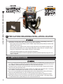
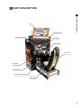
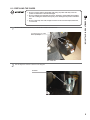
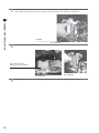
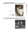
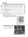
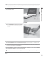
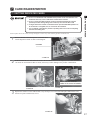
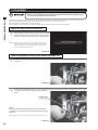
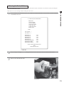
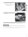
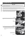
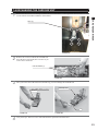
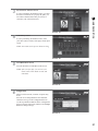
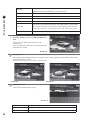
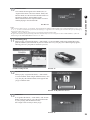
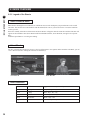
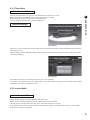
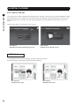
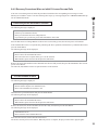
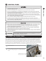
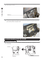
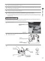
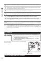
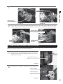
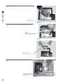
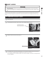
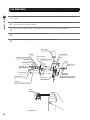
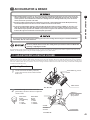
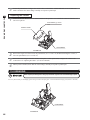
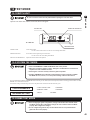
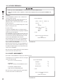
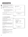
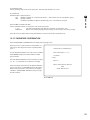
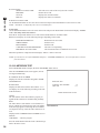
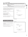
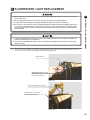
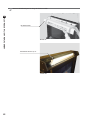
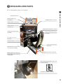
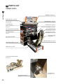
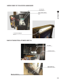
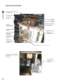
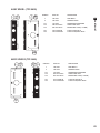
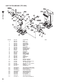
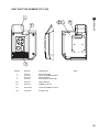
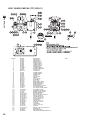
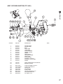
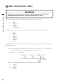
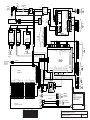
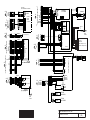
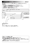
9
CONTROL PANEL
4
5
6
7
8
9
10
11
Remove the nuts that secure the VR bracket, and detach the volume from the VR bracket (see 9-2 FIG. 04).
Using wire cutters or a knife, remove the heat-shrinkable tubing that covers the soldered parts. Melt the solder
with a soldering gun, and detach the volume from the wires.
Cover each wire separately with the heat-shrinkable tubing. Solder the wires to each of the new volume’s terminals. Carefully check the wiring schematic when connecting the wires to the volume.
Cover the soldered parts with heat shrinkable tubing, and use the dryer to apply heat until the tubing adheres to
the soldered parts. Reattach the VR bracket and gear holder to the volume.
While the steering wheel is centered, engage the volume axis with the gear, making sure that the D-cut flat side
is aligned as indicated in the diagram. Then secure the VR bracket with two screws (see 9-2 FIG 01).
Turn the steering wheel and check that the gear moves smoothly. Reattach the connector. Close the control
panel and secure it.
Switch on the unit. Be careful not to touch the steering wheel when doing so. After the unit is switched on, the
steering wheel undergoes automatic initialization.
Configure the volume values on the INPUT ASSIGNMENTS screen in Game Test Mode.
It is recommended that the steering wheel volume be set to 80H±8H when the steering wheel is centered. Confirm that when the steering wheel is turned to the left the numbers decrease, and when it is turned to the right the
numbers increase (see Service Manual).
9-3 GREASING
● Use only the specified grease. Using any other kind of grease can result in damage to
parts.
● Do not apply grease to locations other than as specified. Doing so may create a risk of
operational problems and deterioration of parts.
● The period for greasing specified herein is a standard. Apply greasing to the specified
portions as occasion arises.
Once every three months, apply grease to the parts indicated. Use Grease Mate-brand spray
grease (Part No.: 090-0066).
9-3 FIG. 01
Apply grease.
9-4 STOPPER RUBBER REPLACEMENT
Refer to the section “9-1 Opening the Control Panel”, and open the control panel.
38