1
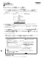
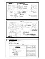
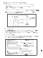
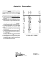
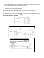
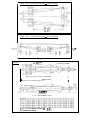
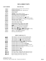
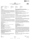
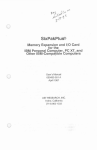
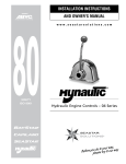
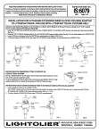
L
/nc.
P.O. Box 908
Osprey, Florida 34229
Telephone 813-966-2151
ANUAL HY
ULIC STEERING
INSTALLAT
AND SERVICE
MANUAL
THIS MANUAL SHOULD BE KEPT ON BOARD YOUR VESSEL.
LIMITED WARRANTY POLICY
“HYNAUTIC” TRADEMARK PRODUCTS
Sta-Rite Fluid Power Group,
-
STA-RITE/ WICOR
(813) 966-2151
The Hynautic Division of Sta-Rite Industries, Inc. warrants that its manufactured products shall be free from defects in materials and workmanship for a period of twenty-four
(24) months from the date of original manufacture. Hynautic will rebuild or replace, at its option, all products of its manufacture proven to its satisfaction to be defective within such warranty period and returned to Hynautic, transportation charges prepaid. Hynautic’s sole obligation, and buyer’s exclusive remedy hereunder, is limited to such rebuilding or replacement.
No products may be returned to any Hynautic factory unless the prior consent for said
return shall have been obtained from the Hynautic Customer Service Department in Osprey,
Florida. This Limited Warranty does not cover shipping costs to and from the Hynautic factory, any costs for labor or otherwise related to product removal or replacement, or any other
costs of any nature without prior consent by Hynautic.
Parts, products and accessories made by others are warranted only to the extent of the
original manufacturer’s warranty to Hynautic.
This warranty shall not apply to acts of God, war or civil insurrection, nor shall it apply
to products which, in the sole judgment of Hynautic have been subject to negligence, abuse,
sanctioned racing events, accident, misapplication, tampering, alteration; nor due to improper
installation, operation, maintenance or storage; nor to other than normal application, use or
service, including but not limited to, operational failures caused by foreign materials in the
system, or operation at pressures in excess of recommended maximums.
Purchaser shall be solely responsible for determining suitability for use of the Hynautic
products. Neither Sta-Rite nor Hynautic shall, in any event whatsoever, have any liability with
respect to such determination.
THE FOREGOING WARRANTY IS EXCLUSIVE AND IN LIEU OF ALL OTHER WARRANTIES, EXPRESS OR IMPLIED, INCLUDING BUT NOT LIMITED TO THE IMPLIED WARRANTIES OF MERCHANTABILITY AND FITNESS FOR A PARTICULAR PURPOSE.
HYNAUTIC SHALL NOT BE LIABLE FOR ANY CONSEQUENTIAL. INCIDENTAL OR CONTINGENT DAMAGES WHATSOEVER.
NOTE TO CONSUMERS: THIS LIMITED WARRANTY IS EXTENDED TO THE COMMERCIAL CUSTOMERS, DEALERS AND INSTALLERS OF HYNAUTIC ONLY. THE SUPPLlERl/NSTALLER WILL EXTEND WARRANTY COVERAGE TO YOU WHICH COVERS
HYNAUTIC’S PRODUCTS. HYNAUTIC’S WARRANTY TO SUCH CUSTOMERS, DEALERS
AND INSTALLERS WILL BACK UP THE WARRANTY EXTENDED TO THE CONSUMER.
181002
REV2
I
INSTALLATIOR INSTRUCTIONS: HOW AND WHY
YOUR HYNAUTilC
STEERING SYSTEM
181001
WORKS
There a r e f o u r b a s i c e l e m e n t s t o y o u r H y n a u t i c S t e e r i n g S y s t e m :
t h e helm. t h e r e s e r v o i r . t h e r e l i e f v a l v e
and the cylinder.
I n some Hynautic
systems t h e r e l i e f v a l v e h a s been mounted d i r e c t l y t o t h e b o t t o m o f
t h e r e s e r v o i r . w i t h t h e c o m p l e t e a s s e m b l y b e i n g termed a r e s e r v a l v e .
The s t e e r i n g s t a t i o n a s s e m b l y I n c l u d e s a h y d r a u l i c pump and p i l o t check v a l v e a s s e m b l y .
Rotating the s h i p ' s
wheel m o v e 6 s e v e n s m a l l P i s t o n s i n a r h y t h m i c , b u t c o n t r o l l e d . p a t t e r n .
T h e r e p i s t o n s , i n t u r n , pump hydraulic
f l u i d t o the s t e e r i n g cylinder.
I n t e r n a l l y l o c a t e d i n t h e s t e e r i n g s e n d e r a r e two p i l o t check v a l v e a s r e s b l i e r .
These i s o l a t e e a c h S t e e r i n g s t a t i o n from a l l o t h e r s . They a l s o l o c k t h e r u d d e r a n d e l i m i n a t e ' k i c k b a c k ' from
t h e r u d d e r t o t h e steering
wheel.
E x t r a h y d r a u l i c f l u i d a n d a p r e s s u r e h e a d f o r t h e ' s y s t e m i s m a i n t a i n e d by t h e r e s e r v o i r ( o r r e r e r v a l v e ) .
The
t w o q u a r t s Of h y d r a u l i c f l u i d ( t h e r e r e r v a l v e S t o r e s one q u a r t ) u n d e r a p r e s s u r e
r e s e r v o i r s t o r e s approximately
of 20 p s i .
T h i s p r e v e n t s a i r from e n t e r i n g t h e system.
located on t h e r e s e r v o i r ( o r reservalve)
i s an a i r
v a l v e and a p r e s s u r e g a u g e . which shows t h a t t h e reservoir
( o r r e s e r v a l v e ) i s charged t o the proper p r e s s u r e .
The h y d r a u l i c f l u i d i n t h e r e s e r v o i r ( o r r e s e r v a l v e ) p a s s e s t h r o u g h a s i n t e r e d b r o n z e f i l t e r u p o n i t s e x i t
from t h e r e s e r v o i r ( o r reservalve).
t h e r e b y p r e v e n t i n g d i r t from e n t e r i n g t h e s y s t e m . H y d r a u l i c f l u i d f r o m
t h e r e s e r v o i r ( o r r e s e r u a l v e ) P a s s e r i n t o t h e s y s t e m t h r o u g h check v a l v e s l o c a t e d i n t h e helm pump.
P r o t e c t i o n of b o t h t h e m e c h a n i c a l p o r t i o n of t h e r u d d e r ( S h o u l d t h e r u d d e r S t r i k e 1 s o l i d o b j e c t ) and h y d r a u l i c
f a c t o r y s e t a t 500 o r 950 p s i . The r e l i e f v a l v e i s c o n n e c t e d
s y s t e m i s h a n d l e d by 1 r e l i e f v a l v e assembly,
between t h e s t e e r i n g c y l i n d e r and t h e r e s e r v o i r ( i n t h e c a s e o f t h e r e s e r v a l v e i t s mounted d i r e c t l y t o t h e
bottom of t h e r e s e r v o i r ) . L o c a t e d i n t h e r e l i e f valve a r e two s m a l l s i n t e r e d b r o n z e f i l t e r s and a s t h e u n i t
r e l i e v e s h y d r a u l i c f l u i d t o t h e reservoir,
t h e y f i l t e r O u t any f o r e i g n m a t e r i a l t h a t may have been e n t r a p p e d
i n t h e l i n e s o f t h e f l u i d . T h i s r e l i e v i n g f e a t u r e a l l o w s a i r t o b e e a s i l y r e m o v e d f r o m t h e s y s t e m by a
constant
r o t a t i o n of t h e s t e e r i n g wheel i n t h e s a m e d i r e c t i o n a f t e r i t h a s r e a c h e d hardover.
This a c t i o n
forces a l l t h e a i r out of the system through the r e l i e f valve a n d i n t o t h e r e s e r v o i r .
progreressively
S T E E R I N G SYSTEM
C O N F I G U R E D WITH S E P A R A T E R E S E R V O I R A N D R E L I E F V A L E
// 11 I/
HELH UNIT
7
v
R E L I E F VALVE
uu
CYLINDER
R E L I E F V A L V E PURGlNG SCREWS
HYNAUTIC STEERING 8 Y . m
CONFIGURED U l T H RESERVALVE
I/ 1il
HELM UNIT
RESERYALVE
C Y L I N OER
T h e r e l i e f v a l v e - r e s e r v o i r r e l a t i o n s h i p i n t h e s y s t e m p ~ e v e n t s t h e r m a l e x p a n s i o n or c o n t r a c t i o n d u e t o
t e m p e r a t u r e changes from r u p t u r i n g or c a u s i n g ' a i r p o c k e t s ' i n t h e s y s t e m .
S t e e r i n g c y l i n d e r a s s e m b l i e s are d o u b l e a c t i n g , e i t h e i d o u b l e rod e n d or s i n g l e r o d e n d t y p e s . r i g i d l y
mounted. b a l l j o i n t mounted o r u n i v e r r l l y mounted.
Cylinder rods are non-magnetic s t a i n l e s s steel.
M a n u a l h y d r a u l i c s t e e r i n g c a n b e u s e d o n any b o a t w h i c h C a n b e s t e e r e d m a n u a l l y . S h o u l d a g r e a t e r t o r q u e
b e r e q u i r e d on t h e r u d d e r t h a n i s Shown i n t h e s y s t e m p e r f o r m s n c e d a t a f o r t h e 5 y s t e s r e c e i v e d . t h e r u d d e r
a m l e n g t h may b e i n c r e a s e d . T h i s w o u l d i n c r e a s e t h e t o r q u e o n t h e r u d d e r b u t d e c r e a s e t h e t o t a l r u d d e r
arc,
A s e c o n d method Would b e t o i n c r e a s e t h e c y l i n d e r ' s b o r e s i z e , t h i s would i n c r e a s e t h e s y r t e n ' r
o u t p u t f o r c e , t h e r u d d e r arm l e n g t h w o u l d r e m a i n t h e same, b u t t h e h e l m t u r n s w o u l d i n c r e a s e . A n o t h e r
method would be t o add a second s t e e r i n g c y l i n d e r ( i n P a r a l l e l with the f i r s t s t e e r i n g c y l i n d e r ) t o t h e
system.
T h i s w o i i l d d o u b l e t h e t u r n i n g t o r q u e o n t h e r u d d e r , b u t i t w o u l d a l s o d o u b l e t h e n u m b e r o f turns
from hardover t o hardover.
If you question the installation or application of a Hpnautic system, contact Hynilutic, Ins.,P.O.BOX 908, Osprey, F134229,(813)/966.
2161).
INSTALLATION INSTRUCTIONS:
PREPARATION FOR INSTALLATION
1.
R e a d t h e i n r t a l l a t i o n i n s t r u c t i o n s b e f o r e a n y Work i s s t a p t e d . P u r g i n g a n d T r o u b l e s h o o t i n g i n s t r u c t i o n s
h a v e b e e n i n c l u d e d i n t h e s y s t e m b o x , while component i n s t a l l a t i o n i n s t r u c t i o n s h a v e been p a c k e d w i t h
t h e s p e c i f i c c o m p o n e n t . M i s s i n g i n s t r u c t i o n s elin b e O b t a i n e d f r o m y o u r H y n a u t i c d i s t r i b u t o r . o r
Hyndutic, lnc.
2.
Before i n s t a l l a t i o n i s s t a r t e d , verify t h a t a complete system has been received.
3.
I t i s recommended t h a t a l l s y s t e m c o m p o n e n t s b e i n s t a l l e d p r i o r t o r u n n i n g t h e s y s t e m t u b i n g .
a l l o w s t h e t u b i n g t o b e r u n b e t w e e n two d e f i n i t e p o i n t s w i t h less C h a n c e o f a h o o k - u p e r r o r .
4.
I f 7t i s o e c e i s i l r y f o T t h e t u b i n g t o b e s t r u n g f i r s t , a s y s t e m o f m a r k i n g t h e d i f f e r e n t t u b i n g runs
Should be used.
5.
DO
6.
Dry s e a l t h r e a d s and h i g h q u a l i t y f i t t i n g s a r e u s e d t h r o u g h o u t y o u r H y n i u t i c s y s t e m .
Do n o t u s e
P e w a t e x o r f o r m a t e x , or s i m i l a r t y p e t h r e a d s e a l a n t s , on t h e p i p e j o i n t s w h e n i n s t a l l i n g t h e f i t t i n g s
S h o u l d t h i s S e a l a n t be I n t r o d u c e d i n t o your s y s t e m , a m a l f u n c t i o n c o u l d r e s u l t . The o n l y S e a l a n t
H y n a v t i c r e c o m m e n d s f o r p i p e t h r e b d i i s L o c t i t e H y d r a u l i c S e a l a n t 869-31, a n d L o C q u i f P r i m e r G r a d e
T 147-56. Again. t h i s s e a l a n t s h o u l d be u s e d w i t h c a u t i o n a n d very s p a r i n g l y .
7.
CLEANLlNESS I S E X T R E M E L Y IMPORTANT. C a r e s h o u l d b e t a k e n t o p r e v e n t c h i p s or a n y f o r e i g n m a t t e r f r o m
g e t t i n g i n t o t h e components or t u b i n g b e f o r e o f d u r i n g i n s t a l l a t i o n .
8.
I n s t a l l a t i o n i n S t r u c t i o n s h a v e b e e n m a d e as c o m p l e t e , b u t a s b r i e f , a s p r a c t i c a l .
q u e s t i o n s , c o n t a c t y o u r d i s t r i b u t o r , or H y n a u t i c , I n c .
n o t u s e a n y t h r e a d l u b r i c a n t o r s e a l e r on t h e f l a r e d t u b e f i t t i n g s . U h e n
on t h e p i p e f i t t i n g s , t a k e c a r e n o t t o i n d u c e t h e s u b s t a n c e i n t o t h e s y s t e m .
HYNAUTIC, INC.
P.O. Box 908 Osprey, Florida 34229 Telephone 813-966-2151
"I
This
thread lubricant
I f y o u h a v e an)
INSTALLATION INSTRUCTIONS: MOUNTING SERiES 20 AND SERIES 40 HEW UNITS
1.
H e l m u n i t d i m e n s i o n s a n d l a y o u t s a r e g i v e n on t h e b a c k o f t h i s s h e e t .
2.
T h e S h a f t may b e a t a n
The h e l m u n i t s m a y b e m o u n t e d w i t h t h e t u b i n g p o r t s u p , down or i n any p o s i t i o n .
angle i f so desired.
V e r i f y a f t e r m o u n t i n g t h a t t h e h e l m u n i t ' s s h a f t does n o t b i n d on t h e p a n e l .
3.
A t e m p l a t e i s p r o v i d e d , t h i s may b e u s e d f o r l o c a t i n g t h e s h a f t a n d m o u n t i n g h o l e s .
If t h i s t e m p l a t e i s
u s e d , t h e d i r e c t i o n O f t h e t u b i n g p o r t s w i l l c o r r e s p o n d t o t h e h o r i z o n t a l and v e r t i c a l l i n e r d r a w n on
the template.
4.
F o r the helm u n i t ' s S h a f t
I
1-114" d i a m e t e r h o l e p r o v i d e s t h e p r o p e r C l e a r a n c e .
"011:
51"s i t l C i " "I'
T*
t i i r r o ,is- P i " $ S A X E L inltr"LI5
5.
~ x t r e m e care m u i t be t a k e n t o u s e t h e c o r r e c t l e n g t h 3 / 8 - 1 6 N F s t u d s .
These a r e p r o v i d e d b y t h e b o a t
b u i l d e r , o r o w n e r . a n d s h o u l d n o t e x c e e d the t h i c k n e s s o f t h e c o n s o l e by more t h a n 7 / 8 o f a n i n c h ,
6.
R o t a t i n g the s t e e r i n g wheel i n a c l o c k w i s e d i r e c t i o n w i l l
The s t e e r i n ? , p o r t s a r e m a r k e d ' S ' a n d ' P ' ,
p r e s s u ~ i z e s , r o t a t i n g i t I " t h e c o u n t e r c l o c k w i s e d i r e c t i o n w i l l p r e s r u r i r e 'P'.
INSTALLATION INSTRUCTION:
TUBING
-
1.
,032'' w a l l t h i c k n e s s .
C o p p e r t u b i n g can b e u s e d on h i g h p r e r s u r e , a p p l i c a t i p n s . P S l i n e s
COPPER TUBING
r e q u i r e 3 1 8 " o r 1 / 2 " c o m p r e s s i o n 0 1 f l a r e f i t t i n g s . R l i n e r r e q u i r e 114" c o m p r e s s l n n or f l a r e f i t t i n g s .
2.
Use e i t h e r H y n l u t l C s u p p l i e d h o s e o r t h e
H i g h p r e s s u r e hose m a y be u s e d t h r o u g h o u t y o u r System.
HOSE
P L S l i n e s r e q u i r e 3 / 8 " or 1 1 2 "
e q u i v a l e n t o f A e r o q u i p 2 6 5 1 ( S A E 1 O O R w i t h 1000 p s i w o r k i n g p r e s s u r e ) .
l i n e s , R l i n e s r e q u i r e 114".
-
INSTALLATION INSTRUCTION:
1.
FLUlOS
Use M I L - 0 - 5 6 0 6 A i r c r a f t H y d r a u l i c F l u i d , T e x a c o # I S , S h e l l T e t l u r 15 ( 1 8 0 - T e l l u r 10) o r C h e v r o n E P - M a c h i n e
LIGHT V I S C O S I T Y OILS A R E RECOMMEDEO. HEAVIER OILS WILL CAUSE S Y S T E M STIFFNESS.
O i l 10.
DUAL STATION STEERING SYSTEM
-
'
RESERVOIR
I
NOTE:
F l e x i b l e l i n e s are r e q u i r e d ( 2 p c s . ) .
Use H y n a u t i c s u p p l i e d hose o r t h e
e q u i v a l e n t o f S A E l O O R w i t h 1000 p s i
working pressure.
2.
When u s i n g 4 . 0 o r 5.5 c b - i n h e l m
p u m p s , P 6 S l i n e s a r e 112" d t a .
and R l i n e s 3 / 8 " d l d .
2EE5RELIEF VALVE
7
CYLINDER
___
MOOEL
SHOWN:
4.75
HVNI740037
H-21
H- 22
i
_
-
I
p
L
-
5.5
ti-30
--__
Y9 WOODRUFF K E Y
w
p.75r
HYN.650027
3 / 8 - 1 6 MTG H O L E S
(0
HYN8270037
PLACES
-1 / 2 - 2 0 T H D
rc.7 5
M O HO -E2L 5 N O .
i?tNA71001i
HYNt340041
4
+6.!25
MOOEL NO.
H- 26
I
NOTE:
-W
z
4
1
5
WOODRUFF
H Y N Y 6 5 0 0 3 6K E Y
SEE 'HELM MOUNTING
T E M P L A T E ' FOR M O U N T I N G HOLE LOCATION.
#?
H Y N i 740037
HYNR 650047
6.13
3/8- 16 U N C - I l 2 " D P .
MTG. n o u s ( 4 )
I N S T A L L A T I O N NOTE:
3.5
(1)
A L L PORTS ARE 1 / 4 - 1 8 N P T F
(2)
T U B I N G RECOMMENDATION
3/8" O.D.
C O P P E R T U B I N G FOR ' R ' L I N E A N D l / ? "
0 . 0 . C O P P E R T U B I N G FOR ' P ' b ' S ' L I N E S .
i
-
H E L U M D D E L SHOWN: H - 4 1 O R H - 4 2
HELM U N l T S P L C l f I C A T l O N S
'5' P o r t C l o C k w i S e R o t a t i o n D i s c h a r g e
' P ' P o r t C o u n t e r Clockwise R o t a t i o n D i s c h a r g e
' R ' Port Reservoir
S e r v i c e P r e s s u r e : 1000 p s i .
M a x i m u m S h a f t S p e e d : 7 5 rpm.
F l u i d : C l e a n P e t r o l e u m O i l , 50 t o 2 0 0 S . U . S . @
HELM U N I T NO.
I" S t r a i g h t
T e l e f l e x Taper ( 1 " I f t . )
Auto Pilot
HELM DISPLACEMENT
2.00 cu-in/rev.
2.75 c u - i n l r e v .
4.00 c u - i n l r e v .
5.50 c u - i n l r e v .
100 F
INSTALLATION INSTRUCTIONS: MOUNTING THE RESERVOIR (R-06, R-07 AND R-08)
1.
2.
H o u n t t h e r e s e r v o i r i n a n u p r i g h t p o s i t i o n where i t w i l l b e easy t o f i l l , p r e s s u r i z e .
gauge a n d v i e w t h e f l u i d l e v e l i n d i c a t o r s .
read the pressure
INSTALLATION NOTE
Y h i l e t h e r e s e r v o i r can b e l o c a t e d any P l a c e i n t h e b o a t . s y s t e m p u r g i n g w i l l b e e a s i e r i f i t i s n e a r t h e
T h i s i s p a r t i c u l a r l y i m p o r t a n t w h e r e l o n g runs o f t u b i n g are i n v o l v e d , as i n v e r y l a r g e b o a t s .
helm u n i t s .
h o u s e b o a t s and s p o r t f i r h e r m a n w i t h t u n a t o w e r s .
i n t h e s e i n s t a n c e s i t i s recommended t h a t t h e r e s e r v o i r b e
" '*
mounted forward, h i g h i n t h e boat. and c l o s e t o t h e helm u n i t s .
.I
3.
I t s h o u l d b e n o t e d t h a t t h e p o r t on t h e b o t t b m o f t h e h e x a g o n a l f i l t e r p l u g i s t h e s u p p l y p o r t .
from t h i s p o r t goes t o t h e h e l m u n i t s .
4.
The p o r t on t h e b o t t o m o f t h e r e s e r v o i r b a d y i s t h e r e t u r n p o r t .
r e l i e f valve.
5.
When t i g h t e n i n g f i t t i n g s a t t h e r e s e r v o i r ,
a S s e m b l i e S on t h e r e s e r v o i r .
6.
A complete s e t of p u r g i n g i n s t r u c t i o n s are a f f i x e d t o t h e s i d e of the r e s e r v o i r .
r e p l a c e m e n t , copy b e r e q u i r e d , c o n t a c t H y n a u t i c , I n c .
7.
CAUTION
use a backup wrench.
The l i n e f r o m t h i s p o r t goes t o t h e
This w i l l prevent d i s t o r t i o n o f the f i t t i n g
D i r t a n d f o r e i g n m a t t e r i n t h e h y d r a u l i c r y s t e m c a u s e s damage a n d n a l f u n c t i o n .
f i l l i n g system.
S e a l a n t s may b e u s e d w i t h c a r e .
Should an a d d i t i o n a l .
O I L 6 A I R FILLER PLUG
H Y N d 380020
2 8 O I A M T G HOLES
(4)
FLUID L t V E
1N O 1 CATOR
9.81
13.63
1
MINIMUM
FLU10
I-
4.5
10.31
TOP l V l E W
2.wu
(TO HELMS)
-
4.88
-
iYNAUTIC, INC.
'.O. Box 908 Osprey, Florida 34229 Telephone 813-966-2151
or
Use due c a r e i n p i p i n g a n d
/-
G A G E 0 TO 60 P S I
-HYN~
160012
i
The l i n e
I N S T A L U T I O N INSTRUCTIONS:
AND MSV-21)
MOUNTING THE RELIEF VALVE (MSV-19
1.
The r e l i e f v a l v e s h o u l d be m o u n t e d above t h e c y l i n d e r i n o r d e r t o h e l p t h e p u r g i n g p r o c e s s .
2.
INSTALLATION NOTE
M o u n t i t where Y O U can g e t a t t h e b r a s s s c r e w s .
You m u s t have a c c e s s t o t h i s v a l v e f o r P u r g i n g .
3.
I t i s b e t t e r t o mount 'this V a l v e w i t h t h e brass
4.
WARNING
S E ~ ~ Wup.
I
A f t e r p u r g i n g , s c r e w down t h e v a l v e s c r e w s or t h e c y l i n d e r w i l l be b y p a r r e d .
5.
t h i s w i l l r e s u l t i n no r t e e r i n p !
CAUTION
D i r t and f o r e i g n m a t t e r i n t h e h y d r a u l i c S y s t e m c a u s e s damage a n d m a l f u n c t i o n .
f i l l i n g s y s t e m . S e a l a n t s may be u s e d w i t h c a r e .
U s e due c a r e i n p i p i n g a n d
SETTING
MSY-19
MSY- 21
I
INSTALLATION INSTRUCTION:
I
I
500 P S I
950 PSI
I
TUBING
1.
C O P P E R TUBING
,032" w a l l t h i c k n e s s . C o p p e r t u b i n g c a n be u s e d on h i g h p r e s s u r e a p p l i c a t i o n s .
P ir 5 l i n e r
r e q u i r e 318" o r 112" c o m p r e s s i o n or f l a r e f i t t i n g s . R l i n e s r e q u i r e 114" c o m p r e s s i o n O P f l a r e f i t t i n g s .
2.
HOSE
H i g h p r e s s u r e h o s e may b e u s e d t h r o u g h o u t y o u r s y s t e m .
Use e i t h e r H y n a u t i c s u p p l i e d h o s e o r t h e
P & S l i n e r r e q u i r e 318" o r 1 1 2 "
e q u i v a l e n t O f A e r o q u i P 2 6 5 1 ( S A E l O O R w i t h 1000 p s i w o r k i n g p r e s s u r e ) .
l i n e r , R l i n e s r e q u i r e 114".
~
-
INSTALLATION INSTRUCTION:
1.
FLU108
U s e M I L - 0 - 5 6 0 6 A i r c r a f t H y d r a u l i c F l u i d , T e x a c o Y15, S h e l l T e l l u s 15 ( 1 8 0 - T e l l u r 1 0 ) or C h e v r o n EP-Machine
LIGHT Y I S C O S I T Y OILS A R E RECOflMENDEO, HEAVIER OlLS WILL CAUSE S Y S T E M STIFFNESS.
O i l 10.
DUAL S T A T E N S T E E R I N G SYSTEM
HELM UNIT 12
NOTE:
1.
When u s i n g 2 . 7 5 c u - i n h e l m pumps,
P L S l i n e r a r e 318'' d i a . a n d R
l i n e r 114" d i a ,
2.
When u s i n g 4 . 0 o r 5 . 5 c u - i n h e l m
pumps, P 6 S l i n e s a r e 1 1 2 " d i s .
a n d R l i n e s 318" d i a .
/I
RELIEF Y A L Y E
nOTE:
Flexible lines are required ( 2 P
C
Use H y n i u t i c s u p p l i e d h o s e o r t h e
e q u i v a l e n t o f S A E l O O R w i t h 1000 p s i
working pressure.
S
.
)
.
~
CYLINDER
STEM PURGlNG YHI
FlLLlNG
RE!
-
AND
__
EPARATE RE1 EF VALVE ARE USEO
IN
THE SYSTEU
A N D PRESSURIZING THE SYSTEM
USE HYNAUTlC S T E E R I N G O I L OR LlGHT VISCOSITY HYDRAULlC O I L T H A T MEETS THE AlRCRAFT
HYDRAULIC FLUID S P E C MIL-11-5606, SUCH AS TEXACD 115. E X X O N UNIVIS 3 - 1 3 , CASTROL AYH-15,
CASTROL AERO-585-8, O R SHELL TELLUS 1 5 . HEAVIER OILS, SUCH AS AUTOMATIC TRANSHlSSION
O I L TYPE A OR OEXTRON 11. MAY BE USED BUT Y I L L CAUSE HARDER S T E E R I N G .
1.
L o c a t e t h e t w o s c r e w s w i t h p i n n e d 112" h e x n u t s on t h e top o f t h e r e l i e f v a l v e .
b y hand. t u r n i n g C o u n t e r c l o c k w i s e u n t i l t h e y S t o p .
2.
Remove t h e h e x p l u g f r o m t o p o f t h e r e s e r v o i r and f i l l v i t h o i l t o w i t h i n 112" o f t h e t o p
r e p l a c e t h e hea p l u g .
3.
The r e s e r v o i r i s e q u i p p e d w i t h a t i r e t y p e a i r v a l v e .
Rny t i r e a i r pump o r c o m p r e s s e d a i r s u p p l y
can b e u s e d t o p r e s s u r i z e t h e S y s t e m . S l o u l y p r e s s u r i z e t h e r e s e r v o i r t o 4 0 - 4 5 p s i . As pressure
i s a p p l i e d . o i l w i l l f l o w i n t o t h e System.
Yhen t h e o i l l e v e l d r o p s t o w i t h i n 2 i n c h e s o f t h e b o t t o m
o f the reservoir, stop pressurizing.
E x h a u s t t h e a i r p r e s s u r e t h r o u g h t h e a i r v a l v e . remove t h e h e x
fill p l u g . r e f i l l . a n d r e p l a c e t h e f i l l p l u g .
Repressurize u n t i l the r e s e r v o i r o i l l e v e l s t a b i l i z e s
and gage p r e s s u r e r e a d s b e t w e e n 40- 45 p s i . Check a l l c o n n e c t i o n s f o r l e a k a g e .
4.
Go t o t h e h i g h e s t h e l m and b l e e d t h e a i r Out o f t h e ( P ) p o r t and ( S ) s t a r b o a r d l i n e s b y c r a c k i n g Open
the f i t t i n g connections.
A l l o w t h e a i r t o e s c a p e u n t i l o i l appear^. and t h e n r e t i g h t e n .
5.
D i s c o n n e c t t h e C l e Y i S O r T O d e n d O f t h e cylinder f r o m i t s e n g i n e O I r u d d e r AlOYntlng If a t a l l
possible. making c e r t a i n i t i s f r e e t o s t r o k e w i t h o u t i n t e r f e r e n c e .
This w i l l a s s i s t i n purging the
a i r from t h e cylinder.
6.
B l e e d b o t h ends O f t h e c y l i n d e r b y b a c k i n g o f f t h e s o c k e t h e a d cap screw b l e e d e r s one t u r n .
I f the
c y l i n d e r i r n o t e q u i p p e d w i t h b l e e d e r s . c r a c k open t h e f i t t i n g C o n n e c t i o n s .
Hold the c y l i n d e r 5 0
b l e e d i n g w i l l be p e r f o r m e d on t h e h i g h e s t end o f t h e c y l i n d e r .
A l l o w the a i r t o escape u n t i l o i l
appears and t h e n c l o s e .
7.
V e r i f y t h a t t h e r e s e r v o i r i s a t l e a s t 314 f u l l and t h e gage r e a d s b e t w e e n 40 a n d 45 p s i .
If o i l
l e v e l i s b e l o w 112 f u l l . e x h a u s t t h e a i r p r e s s u r e t h r o u g h t h e a i r v a l v e , remove t h e fill p l u g , r e f i l l .
and r e p l a c e t h e fill p l u g .
R e p r e s s u r i z e t o 40-45 p s i .
L o o s e n and b a c k o f f
and
PURGING T H E S Y S T E M OF A I R
The f o l l o w i n g p r o c e d u r e i s a p r o c e s s b y w h i c h h e l m ( $ ) a n d a u t o p i l o t are s e q u e n t i a l l y
o p e r a t e d t o pump o i l i n t o t h e ( P I p o r t a n d ( S ) s t a r b o a r d h y d r a u l i c l i n e s . d i s p l a c i n g
t h e a i r - i n f i l t r a t e d o i l o u t through t h e r e l i e f v a l v e and i n t o t h e r e s e r v o i r w h e r e t h e
a i r Separates from t h e o i l .
S o l i d o i l from? t h e b o t t o m O f t h e r e s e r v o i r i s t h e n f e d
b a c k t o t h e h e l m and a u t o p i l o t t h r o u g h t h e ( R ) l i n e a s needed.
The number o f w h e e l t u r n s s p e c i f i e d b e l o w h a v e been e s t a b l i s h e d f o r a v e r a g e t u b i n g
If t u b i n g l e n g t h s e x c e e d 20 f e e t . i n c r e a s e
l e n g t h s O f 20 f e e t b e t v e e n c o m p o n e n t s .
t h e number o f t u r n s b y 2 f o r every e x t r a f o o t O f t u b i n g l e n g t h .
1.
Go t o t h e h i g h e s t h e l m and t u r n s l o ~ l y( 2 t o 3 s e c l r e v . ) 60 t i m e s i n one d i r e c t i o n .
2.
Repeat S t e p 1 a t e a c h s u c c e s s i v e l y l o w e r h e l m a n d a u t o p i l o t
NOTE
P u r g i n g a i r f r o m a n h y d r a u l i c a u t o p i l o t i s a c c o m p l i s h e d b y s e t t i n g a c o u r s e on
t h e a u t o p i l o t t o t h e sane d i r e c t i o n y o u are s t e e r i n g t h e h e l m ( s 1 .
If you a r e
s t e e r i n g the helm(s) t o the Starboard (clockwise) d i r e c t i o n , Set a s t a r b o a r d
C o u r s e h e a d i n g on t h e a u t o p i l o t a n d a l l o w i t t o run f o r 1 t o 2 m i n u t e s .
3.
Once n o r e . c r a c k t h e b l e e d e r s a t t h e c y l i n d e r .
If b l e e d e r s are n o t a v a i l a b l e . c r a c k t h e f i t t i n g s
a t t h e a p p r o p r i a t e ends and a l l o w t h e a i r t o b l e e d o u t .
R e t i g h t e n when s o l i d o i l a p p e a r s .
4.
Check t h e r e s e r v o i r pressure a n d o i l l e v e l .
I f o i l l e v e l i s below the h a l f f u l l n a r k . exhaust t h e
a i r p r e s s u r e t h r o u g h t h e a i r v a l v e . remove t h e o i l fill p l u g . r e f i l l . a n d r e p l a c e fill P l u g .
R e p r e s s u r i z e t o 40- 45 p s i .
5.
Go t o t h e h i g h e s t h e l m and t u r n t h e w h e e l s l o w l y 6 0 t u r n s i n t h e OPPOSITE d i r e c t i o n .
s u c c e s s i v e l y lower h e l m and a u t o p i l o t .
6.
c l o s e t h e two r e l i e f v a l v e s c r e w s w i t h p i n n e d h e x n u t s b y t u r n i n g c l o c k w i s e , a n d s n u g w i t h a wrench.
Repeat a t each
- LOSS of
s t e e r i n g w i l l o c c u r i f t h e r e l i e f v a l v e screws are n o t c l o s e d .
Yhen s e c u r i n g t h e s e s c r e w s w i t h a w r e n c h . do n o t a p p l y h e a v y f o r c e
o r damage t o t h e screw a n d r e l i e f v a l v e w i l l r e s u l t .
one d i r e c t i o n u n t i l h e r d o v e r i s f e l t .
7.
Go t o
8.
60 t o t h e c y l i n d e r and open t h e b l e e d e r o r c r a c k t h e f i t t i n g a t t h e e n d o f t h e c y l i n d e r t h a t t h e r o d
i s
from. c l o s i n g when s o l i d o i l a p p e a r s .
9.
A g a i n go t o
I
h e l m S t a t i o n and t u m i n
I
h e l m S t a t i o n a n d t u r n now i n t h e o p p o s i t e d i r e c t i o n u n t i l h a r d o v e r 15 f e l t .
10.
So t o t h e c y l i n d e r and b l e e d u n t i l s o l i d oil appears a t t h e o p p o s i t e end
b l e d and then r e c l o s e .
11.
v e r i f i c a t i o n O f a c o m p l e t e p u r g e i s a c c o m p l i s h e d b y r o t a t i n g t h e h e l m a n d a c h i e v i n g , w i t h i n 112 t u r n .
An eXCeSSiVe
t h e c o r r e s p o n d i n g number o f t u r n s h a r d o v e r t o h a r d o v e r shown on t h e c h a r t b e l o w .
number O f t u r n s i n d i c a t e s a i r i n t h e S y s t e 8 a n d S t e p s 1-10 m u s t b e r e p e a t e d
HYNAUTIC, INC.
P.O. Box 908 Osprey, Florida 34229 Telephone 813-966-2151
Of
the cylinder previouslY
I181006
I
12.
To v e r i f y r e l i e f o p e r a t i o n a n d s y s t e m i n t e g r i t y , go t o I helm a n d t u r n p a s t h a r d o v e r . f o r c i n g o i l
over t h e r e l i e f v a l v e f o r il t u r n o r two a t e a c h h a r d o v e r p o s i r i o n . A s q u e a k may b e h e a r d I S t h e
r e l i e f valve unloads.
13.
S e c u r e t h e c y l i n d e r t o t h e m o u n t i n g s t r u c t u r e and t o t h e e n g i n e o r t i l l e r arm. Check t h e reservoir
f a r f l u i d l e v e l a n d p r e s s u r e . Leave t h e r e s e r v o t r 1 / 2 t a 2 1 3 f u l l a n d b t 20-30 p s i .
S I S T E N C H E C K A N D F I N A L PURGlNG
I t i s recommended t h a t y o u check t h e s y s t e m and p e r f o r m a s h o r t . f i n a l p u r g e a f t e r
a p p r o x . 2 4 h o u r s . A f t e r t h i s t i m e . any l e a k s w i l l be d e t e c t e d : a n d any r e m a i n i n g
small b u b b l e r w i l l have f o r a e d l a r g e r b u b b l e r w h i c h a r e e a s i l y removed.
1.
Observe s y s t e m f o r o i l l e a k s and r e s e r v o i r g a g e f o r p o s s i b l e p r e s s u r e 101s.
__
NOTE
I t i s C o m m o n t o o b s e r v e a 5 p s i p r e s s u r e f l u c t u a t i o n , o n s y s t e n s t h a t are
s u b j e c t t o a t e m p e r a t u r e c h a n g e o f 200F. o r more.
2.
Open t h e r e l i e f v a l v e screws.
3.
S t a r t i n g a t t h e u p p e r helm. t u r n 40 t u r n s t n one d i r e c t i o n . r e p e a t i n g a t s u c c e s s i v e l y lower helms.
Again i n t h e same manner, t u r n t h e h e l n c s ) i n t h e o p p o s i t e d i r e c t i o n .
4.
C l o s e t h e r e l i e f v a l v e s c r e w s and s n u g w i t h a wrench.
5.
V e r i f y t h a t t h e p r o p e r number O f t u r n s h a r d o v e r t o h a r d o v e r h a s b e e n o b t a i n e d .
l e v e l ( 1 1 2 t o 2 1 3 f u l l ) and r e s e r v o i r pressure (20-30 p s i ) .
NOTE
Recheck t h e O i l
I f a l i n e m u s t b e disconnected. e x h a u s t the a i r p r e s s u r e from w i t h i n t h e
r e s e r v o i r and remove t h e f i l l e r p l u g . Then O p e n the r e l i e f v a l v e scpews
t o r e l i e v e a l l pressure in t h e l i n e s . A f t e r work i s completed. reconnect
l i n e s and r e p u r g e t h e s y s t e m o f a i r .
T FACT SHEET
6
HfJna&E
J
K-I, K-2, K-3
Brass Cylinders
Description
Cylinders may be equipped with either stainless steel ball
joint or machined brass clevis.
The Hynautic K-1, K-2 and K-3 are double rod end, tie rod
constructed hydraulic cylinders. Each has a universal
mount which allows two planes of pivot freedom.
Mount is cast manganese bronze with stainless steel bearings and Grade 5-rated ’h-13 stainless screws.
Each model cylinder may be equipped with either a
stainless steel ball joint (designatedwith the suffix ‘B’) or
a brass clevis with stainless steel clevis pin (distinguished
by the suffix ‘C’).
Seals are buna “N” type with TFE backup.
Rating
Porting is through two ‘h” NPTF holes at each end of the
cylinder. As installed, ports should be located facing up
to facilitate cylinder purge.
950 psi rated working pressure. Proof pressure is
established at 4500 psi. Burst pressure is 6800 psi which
is governed by tie rod strength.
Construction
Cylinder output force @ 950 psi:
Cylinder tube is seamless brass alloy 330 and ends are
machined ASTM 8-16 brass. The cylinder and ends are
held in place by four tie rods of ASTM 8-16 brass. The
rod is ARMCO Aquamet 17, or equivalent, stainless steel.
K-1 = 1250 Ibs.
K-2 = 1850 Ibs.
K-3 = 2400 Ibs.
pTq
‘h-18 NPTF (2)
. . Ports
Dia. Mtg.
750 Holes (in.)
1
i
-
-Add
-_j
-
‘
*A’ Retracted
B
Retracted
’
for Clevis:
K-1, K-2=.12”
K-3 = .50”
I
70
75
Cyl. No.
~~
~
K-2
K-3
B
A
I
1
I
21.44
21.44
1
I
26.18
26.18
D
C
I
I
,750
,875
1
I
I
1.75
2.00
1
17.7
22.9
G
F
E
I
.53
.53
,
I
H
I
2.12
2.12
I
I
I
5.75
5.75
I
4.00
4.00
184004
ILLUSTRATED
BREAKDOWN
Models
K-1, K-2, K-3
Parts Description
Item Description
1
Bracket
2
Joint
3
Pivot Pin
4
Screw
5
Bracket
6'
Rod Wiper
7'
Back-up Ring
8'
0-Ring
9
Cylinder End
10'
0-Ring
11
Tie Rod
12
Cylinder Tube
13
Nut
14
Rod Assembly
Cylinder Model
K-1
K-2 & K-3
K-1
K-2 & K-3
K-1
K-2 & K-3
K-1
K-2 & K-3
K-1
K-2 8 K-3
K-1 8 K-2
K-3
K-1 & K-2
K-3
K-1 8 K-2
K-3
K-1
K-2
K-3
K-1
K-2
K3
K-1
K-2 & K-3
K-1
K-2
K-3
K-1
K-2 8 K-3
K-1
K-2
K-3
Part No
Qty.
670022
670042
670051
670061
670077
670087
240577
240667
670012
670032
700088
700078
1
1
252212
252210
211210
211212
560281
560301
560291
211028
211030
211032
420271
420281
500191
500211
500181
270051
270011
550390
550420
550410
1
1
4
4
4
4
1
1
2
2
2
2
2
2
2
2
2
2
2
4
4
1
1
1
4
4
1
1
1
19
Item Description
15'
Cylinder Model
Pert No. Qiy.
Back-up Ring
K-1
252125
2
K-2
252222
2
K-3
252224
2
16'
0-Ring
K-1
211125
1
K-2
211222
1
K-3
211224
1
17
Nu1
Ail
270117
1
18
Bail Joint
K-1, K-2 8
K.3 "6"
670220
1
19
Cievis
K.1 "C"
680261
1
K.2 "C"
680251
1
K.3 "C"
680201
1
20
Pin
K.1 "C"
680097
1
K.2 "C"
680047
1
K 3 "C"
680067
1
21
Cotter Pin
K-1, K-2 8
K.3 "C"
290207
2
' Incorporated in Hynaulic Seal Kits No. KS-11 for K-1, KS-12
for K-2 and KS-13 for K-3.
Note A; Clean and secure with "Loctite 680." Apply 32-34 It. IbS. torque tor model K-1, 60-63ft. IbS. torque tor rnOdels K-2 and K-3.
Note 8 : Clean and secure with "LOCtile 680" to thread area. Apply 40-45 11. Ibs. torque.
Note C: Clean and apply 75-78 in. Ibs. torque lor model K-1, 160-165 in. Ibs. for models K-2 and K-3.
1
w15011 csmmar"
P.O. Box 668
Osprey, FL 33559
Tel. 813-966-2151
Telex 159129
Marine Hydrauhc systems and Products
PRINTED IN U.S.A 9/85
COMPONENT FACT SHEET
H-40 Series
Helm Unit
(H-41 H-41-01 H-41-02,
\
H-49 H-42-02)
.
Description
The ti^ ~ - 4 series
0
Hydraulic~~l~Unit isa bi.directionai,
dual element, fixed displacement, axial piston pump, coupled to
pilot-check and make-upcheck valving.
seal backups and piston glyd rings. Other components are of friction and wear resistance materials to reduce operating torque
and prolong life.
The Datented pump
.
. sections utilize fourteen pistons, each
stroked nine times with one shaft revolution, pushing fluid thru
oortina
" blocks intothe valve section.
Performance
#~~
The valve section includes holding valves to prevent feedback
and to isolate the unit, and compensationvalves to allow the use
of unbalancedcylinders.
Volumetric efficiency:90% at 1000 psi and 12 rpm.
Runningtorque vs. pressu!e:
tiloo
Test Schematic
Clockwise rotation of the shaft discharges fluid thru the "S" port;
counterclockwise rotation effects "P' port discharge. The "R"
port is forthe reservoir connection. Port sizeis%" NPTF.
Service pressure is 1000 psi maximum with proof pressure establishedat2000psi.Maximumspeedis 120rpm.
Construction
Exterior is corrosion resistant aluminum and stainless steel. Internal components - ferrous metal porting block and cylinder
barrel with ground mating surfaces, hardened and ground Steel
pistons, drive keys, needle thrust bearings, Buna "N" seals, TFE
0
1w
MO
300
100
5w
600
100
800
mu
1wo
pressure (PSI)
OTHER SHAFT CONFIGURATIONS ARE AVAILABLE UPON REQUEST
34-10 UNC
I
.
~
~~
It- 5%"
~~~
-~
k3%"--I
--4
Helm Unit
-1
H H H H H
41 42 41 41 42
5
MORSE TAPER:
1" Dia., 3%"A. Taper
1"Straight
Morse T a m
Teleflex Taper
TELEFLEX TAPER:
3/i'
Dia., 1"ift. Taper
%"-2O
4.OCu.ln.iRev.
5SCu.ln.iRev.
1
Patent No. 3,482525
Printed in U.S.A.
ILLUSTRATED
PARTS
BREAKDOWN
Parts Description
Helm
:em
1.
2.
Models
H-41
Description
Nut
Washei
3.
Front Cover Assy
4.
5.
6.
11.
Bearing Race-thin
Bearing-thrust
Bearing Race-thick
0-Ring
Ball Cage
0-Ring
Body Spacer
Key
12.
Shalt
7.
8.
9.
10.
13.
14.
15.
16.
17.
18.
19.
20.
21.
22.
Key-short
Key-long
Bearing Race
Retaining Ring
Ball
Cyl. Barrel Assy
Body Assy
Plate
0-Ring
Vaive Body Assy
23.
Rear Cover Assy
24.
SOC. Hd. Cap Screw
25.
Washer
Seal Kit
A.
ow.
1
1
1
1
1
H-42
H-41-01
H-42-01
H-41-02
H-42-02
H-45
H-41
H-42
H-45
H-45
All Others
ALL
ALL
ALL
ALL
ALL
ALL
ALL
H-41/42/45
Ail Others
H-41
H-42
H-41-01
H-42-01
H-41-02
H-42-02
H-45
ALL
ALL
ALL
ALL
ALL
H-41
H-42
H-41-01
H-42-01
H-41-02
H-42-02
H-45
ALL
ALL
ALL
H-45
All Olhers
ALL
ALL
ALL
ALL
i
t
1
1
-
i
1
2
2
2
2
2
4
2
t
t
1
1
1
t
1
1
1
1
18
2
2
2
2
2
2
2
1
1
3
1
1
1
8
1
HS-04
CAUTION
Disassembly of item no's. 19 8 22 will void any existing
warranty. If you disassemble the entire unit. the ball
cages (No.8) must be properly aligned with the body
spacers (No. 10) and body assembly (No. 19). Failure
to do so will result in w o r pump performance.To insure
proper liming, align the notched corners of the ball
caoesas iiluslrated with the cornersofthebodvsnacara
-,-_--- a d Doay assembly, usmg as felerence the porl ng of
Ineboay assembly
STA-RITE/
a WICORcompany
P.O. Box 908 Osprey, Florida 34229 Telephone 813-966-2151
me H Y ~ ~ ~ Usystems
I ~ C
aoa ~ioducrs
tRdnnl (Rnu 1)
...._........-------
COMPONENT FACT SHEET
H-20 Series
Helm Unit
(H.21, H-22, H-23, H-25 & H-26)
Description
The Hynautic H-20 Series Hydraulic Helm Unit is a bi-directional,
fixed displacement, axial piston pump, coupled to pilot-check and
make-up check valving.
The patented pump section utilizes seven pistons, each stroked
nine times with one shaft revolution, pushing fluid thru a porting
block into the valve section.
The valve section includes holding valves to prevent feedback
and to isolate the unit, and compensation valves to allow the use
of unbalanced cylinders.
Seal backups and piStOn glyd rings. Other components are of friction and wear resistance materials to reduce operating torque
and prolong life.
Performa nce
Volumetricefficiency:90%at l000psiand 12rpm.
Running torque vs. pressure:
7W-
Clockwise rotation of the shaft discharges fluid thru the "S" port;
counterciockwise rotation effects '*P" port discharge. The "R"
port is forthe reservoirconnection. Port size is%"NPTF.
Service pressure is 1000 psi maximum with proof pressure established at 2000 psi. Maximum speed is 120 rpm.
Construction
Exterior is corrosion resistant aluminum and stainless steel. Internal components - ferrous metal porting block and cylinder
barrel with ground mating surfaces, hardened and ground steel
pistons, drive keys, needle thrust bearings, Buna "N' seals. TFE
Running Torque Efficiency at 1wO PSI-%%
Pressure (PSI)
(on ball cage)
4 Mounting Holes
3/8-16 Thd. 112 Dp.
.
OldMorseTaper,3.1/2"TaperlFt.l"Dia.
Patent No. 3,482,525
Printed in U.S.A.
ILLUSTRATED
WARNING
These Helm Units are manufactured under strict controls and testing procedures. Disassembly of item NO.
Bwillvoidanyexisting warranty.
It is recommendedthat the unit be returnedto Hynautic
or the point of purchase for authorized repair and retest-
I ing.
i
Parts Description
Item
1.
2.
3.
4.
5.
6.
7.
Description
Shaft
Key
Washer
Bearing Race
Retaining Ring
Bail
Cyi. Barrel Assy
8. Valve Body Assy
9.
10.
11.
12.
13.
14.
15.
16.
17.
18.
19.
20.
21.
22.
A
Screw
Gasket
Nut
Washer
Washer
SOC. Hd. CapScrew
Body Assy-Front Cover
Bearing Race- lhin
Bearing- thrust
Bearing Race-thick
0-Ring
Bail Cage
0-Ring
Bodv Spacer
SeaiKii
(with spare 0-Rings)
Helm
Models
-
H-21, 22
H-23
H-25
H-26
H-21, 22
H-23
H-25
H-26
ALL
ALL
ALL
ALL
H-21
H-23
H-25
H-22. 26
ALL
ALL
ALL
H-21, 22
H-23
H-25
H-26
H-21, 22
H-21, 22
ALL
ALL
ALL
ALL
ALL
ALL
ALL
ALL
ALL
ALL
9 2
1
1
1
1
1
1
1
740078
190012
300046
234066
510080
510080
510080
510070
900220
24031 7
390028
340041
270071
270037
270037
74001 1
740037
240367
900300
190004
190001
190003
21 104C
620018
21 1039
900264
HS-02
1
1
1
1
9
1
1
1
1
1
2
1
1
1
1
1
4
1
1
1
1
1
1
2
1
tNote: The valve assembly is tested at Hynautic. Replacement of
individuai valve pads may producevalve leakageorfailure.
CAUTION
I f you disassemble the entire unit, the ball cage
(No. 20) must be properly aligned with the body
spacer (No. 22) and valve body assembly (No. 8).
Failure t o do so will result in poor pump perform.
ance. To insure proper timing: Align the notched
corner of the ball cage as illustrated with the corners of the body Spacer (No. 22) and valve assernbly (No. a), using as a reference the two protruding
bleed screws (No. 9).
STA-RITE/
awlCORcompany
P.O. Box 908 Osprey, Florida 34229 Telephone 813-966-2151
Marine Hydmulrc systems and Pioducfs
1e4002 (RW 3 )
Autopilot Integration
Hynautic steering systems are compatible with most autopilots. Remember that the proper autopilot model to be used
is a recommendation reserved for the pilot manufacturer.
They know our equipment and how it interacts with their components.
Here are a few items to note when selecting an autopilot.
1 , Autopilot selection is usually based upon the hydraulic cylinder in use. However, sometimes boat size and, to a lesser degree, boat speed and steering geometry may be important.
2. Theautopilot's power unit may be of two styles: A) a complete power hydraulic unit with integral hydraulic pump, or
B) an electromechanical power unit which is to be attached to a Hynautic H-29 or H-30 autopilot helm.
Autopilot systems with complete units are the simplest to
install. Those systems coupled to a Hynautic autopilot
helm offerthegreatestflexibility in changing performance.
3. An autopilot system must have not only enough POWER
to sustain the rudder resistance, but also must supply a
proper RATE OF FLOW, which determines rudder
speed.
4. Any hydraulic autopilot added to a Hynautic system must
incorporate a lock-out valve, either internal or external to
the autopilot pump.
5. Attachment of an electromechanical power unit to a
Hynautic autopilot helm can be either with chain and sprocket, or by direct coupling. Obviously, direct coupling only
allows aonetoone ratio.
Sprockets are sized by teeth. A 2 to 1 ratio would require
a 20 tooth sprocket chained to a I 0 tooth sprocket, or a 30
tooth to a 15 tooth, etc.
6. Most autopilots have afeedback system that makes rudder
correction proportionalto the heading error. With Hynautic
steering systems, this autopilot feedback device must be
connected to the rudder (or cylinder). The steering wheel
will not accurately indicaterudder position.
nuna&E.
K-24
K-18
K-12
K-14'
K-10
K-19
K-13'
K*ll*
K-16'
K-1
K-22
K-25
K-27
K-26
K-28
K-29
K-2
K-32
K-3
K-31
K-4
1-'/2 x 5
1.1% x 7
1-'/4 X 7
1-'/4 x 7
1-'/4 x 9-%
1-'% x 9
1-'/4 x 9
1-'/4 X 9
1-7/4 x 9
1-% x 9
1-%X 10
1-% x 10
1-% x 10
1-% x 12
1-% x 12
1-'h x 12
1 -3% x 9
2x8
2x9
2x10
2x12
6.6
7.0
8.6
'8.6
7.5
9.0
'1 1.o
*11.o
'1 1.o
12.1
13.3
13.3
13.3
16.0
16.0
16.0
17.6
20.0
23.1
25.5
30.5
'DISPLACEMENT WHEN PRESSURIZING
THE HEAD END OF CYLINDER
mc.
INSTALLATION INSTRUCTIONS: MOUNTING THE K-I, K-2, K-3 AND K-4 CYLINDERS
I , Cylinder layout and dimensions are shown in Figure 5.
2. The cylinder can he mounted in eithera Crosswise (abeam) direction or a lengthwise (fore and aft) direction to the boat.
3. Select the diagram and dimensional data that best describes your particular installation, see Figures 1 thru 4.The approximate
rudder arc for each oftheindicated installationsis70degrees.
4. The cylinder should he located in a position to insure an unobstructed pathway for flexible hose to go from the relief valve
to thecylinder ports.
5. The rudder arm, or arms; must have an unobstructed arc of travel, with the rudder post packing allowing a free movement
of the rudder arm and rudder.
6. It is most desirable to have a Close filling. hut free, reamed (%'' dia.) clevis pin hole in the rudder arm. This will assure long
pin life.
7. The rudder arm is connected directly to the ball joint on the end of the cylinder rod using a 3A"dia. pin (avaiiable from Hynautic
or fabricated by the installer). Suggested attachment method is shown below.
ASHERS (3)
LF LOCKING NUT
8. OPTIONAL CLEVIS INSTALLATION
The use of a clevis on the cylinder's rod end is an option offered by Hynautic. If a clevis is used, there is no allowance for
installation misalignment. The cylinder and filler arm must swing together in the same plan. There should be no binding and
the clevis pin must he easily removed at any point throughout the rudder arm's travel. Ifclevis option is used all cylinder length
dimensions will increase by '/2 inch.
9. CAUTION
Careshould betakennottoknickorscratchthecylinderrodorleakagewillresult.
10. With the cylinder attached to the rudder arm, position the rudder arm in the midships position and the cylinder in its'centered
position. Now positionthe mounting bracket along the centerline as indicated in the installation figure you have selected.
1 1 . The mounting bracket should he thru-bolted to a substantial member, since it will haveto withstand forces up to 2400 Ibs.
12. CAUTION
Dirt and foreign matter in the hydraulic system causes damage and malfunction. Use extra care when installing fittings and
attaching hoses.Thread sealants may be used with duecare.
13. Cylinder ports are tapped with '/a-18 NPTF threads, %" or %" flare fittings should be used depending on the system being
installed.
14. Flexible hose must be used to connect the cylinder into the system. Flexible hose must meet the SAE lOOR specification
and have a 1000 psi. working pressure.
INSTALLATION INSTRUCTIONS: TUBING
- .032'. wall thickness. Copper tubing can be used on high pressure applications. P 8 S lines require 3 4 '
or %" compression or flare fittings, R lines require W compression or flare fittings.
1. COPPER TUBING
CAUTION
Coppertubing should not beconnecteddirectlytothecylinder.
2. HOSE - High pressure hose may be used throughout your system. Use either Hynautic supplied hose or the equivalent of
Aeroquip 2651 (SAE 1OOR with 1000 psi working pressure). P 8 S lines require %"or 'h"lines, R lines require 'A''.
INSTALLATION INSTRUCTION: FLUIDS
1. Use MIL-0-5606 Aircraft Hydraulic Fluid, Texaco #15. Shell Tellus 15 (SO-Tellus 10) or Chevron EP-Machine Oil 10. LIGHT
VISCOSITY OILS ARE RECOMMENDED, HEAVIER OILS WILLCAUSE SYSTEM STIFFNESS.
INSTALLATION INSTRUCTION: HELM TURNS
1
FIGURE 1 SINGLE CYLiNDER INSTALLATION-SINGLE HOLE TILLER ARM
_______
FIGURE 2 SINGLE CYLiNDER INSTALLATION-TIE BAR MOUNT
X-DIMENSIONS . These should be determined by the instalier. The iuie
being the cylinder should be mounted on the rudder post side of the tie bar.
With the rudder in the hardover position it Should be as ciose as possible to
and paralleltothetiebar.
!
I
FIGURE 3 DUAL CYLINDER INSTALLATION
-
PARALLEL MOUNT
g ;?
K-l
- !
FIGURE 4 DUAL CYLINDER INSTALLATION
-
2 2
IN LINE MOUNTING
2,K-3
=
1= 10'
FIGURE 5
'F
DIA. MTG.
-18 NPTF (2) PORTS
0
~- /
L
' A RETRACTED
'6 RETRACTED
'D' BORE (IN.)
'E' CYL. DISPLACEMENT (CU-IN.)
K-I, K-2, K-3 CYLINDER STROKE
K-4 CYLINDER STROKE =
=
9.0 IN.
12.0 IN.
I
a"
HELM UNIT #1
DUAL STATION STEERING
SYSTEM
HYNAUTIC, INC.
~
1. When using 2.75 cu-inhev helm pumps, P
8Slinesare3/s"diaandRlinesare'/2dia.
2. When using 4.0 or 5.5 cu-inlrev helm
pumps, P 8 S lines are ,/z" dia and R lines
are3/s"dia.
NOTE
Flexiblelines are required (2 pcs.)
Use Hynauticsuppliedhoseor equivalent
ofSAElOORwithlOOOpsi. working
Dressure.
~
CYLINDER
INSTALLATION INSTRUCTION: SYSTEM PURGING
1. Fillthereservoirtowithin2'ofthetop. Pressurizeto40-50psi.
2. Loosenvalvescrewson the relief valve.
3. Bleed both ends of the cylinder until solid oil appears. This is accomplished by loosening the hose connections at the cylinder and retightening it when solid fluid is evident. Single rod end cylinders bleed rod end
first.
4. Go to highest helm and turn slowly60-70turnsinonedirection. Repeat at successively lower stations.
5. Again bleed at cylinder as in Step 3.
6. Go to top station and turn slowly 60-70turns in the opposite direction. Repeat at successively lower Stations.
7.Again bleed at cylinder as in Step 3.
8. Purging should becompleteatthis time
9. Close valve screwson relief valve, check turns H.0 to H.0
10. Leavesysternpressurize-at25-35psi,and reservoir halffuli
HYNAUTIC, INC.
P.O. Box 908 Osprey, Florida 34229 Telephone 813-966-2151
a WlCOR campan).
I
inc.
181004
I
INSTALLATION INSTRUCTIONS: TROUBLESHOOTING GUIDELINES
.
T h e H y n a v t i c S y s t e m o n b o a r d y o u r v e r s e 1 i s c o n s i d e r e d o n e Of t h e b e s t h y d r a u l i c s t e e r i n g s y s t e m s o n t h e m a r k e t
t o d a y . O v e r t w e n t y y e a r s o f d e v e l o p m e n t a n d c u s t o m e r s a t i s f a c t i o n a r e b e h i n d t h e ~ U E C ~ S oI f H y n a u t i c a n d t h e
systems i t provides.
Each component i n y o u r H y n a u t i c S y s t e m h a s b e e n t h o r o u g h l y t e s t e d a t t h e f a c t o r y p r i o r t o s h i p m e n t .
Helm u n i t s
have been t e s t e d f o r v o l u m e t r i c e f f i c i e n c y and l e a k a g e .
R e ~ e r v o i r s , a n d r e i e r v a l v e s , h a v e b e e n p r e s ~ ~ rt ee s t e d
f o r l e a k a g e over a s e t p e r i o d of t i n e .
Relief valves have been checked f o r leakage and f a c t o r y s e t a t t h e
designated r e l i e f pressure.
C y l i n d e r s h a v e b e e n t e s t e d f o r l e a k a g e a n d o p e r d t i m E t 1000 p s i .
A n o t h e r f a c t o r t h a t s h o u l d b e remembered i s , t h a t H y n a u t i c m a n u f a c t u r e s Manual H y d r a u l i c S t e e r i n g n o t p o w e r
s t e e r i n g ( u n l e s s s p e c i a l o r d e r e d ) , s o t h e e f f o r t r e q u i r e d t o t u r n t h e wheel w i l l i n C r e Q E e a6 t h e s y s t e m i s
c a l l e d o n t o e x e r t more f o r c e on t h e r u d d e r o r o u t d r i v e . A t n o t i m e s h o u l d o n e e x p e c t t h i s s y s t e m t o t u r n
as e a s i l y a s a c a r ' s power s t e e r i n g .
When t u r n i n g t h e s h i p ' s w h e e l t h e o p e r a t o r w i l l b e c a m e a w a r e o f I r h y t h m i c p u l s i n g . t h i s i s n o t a e a l f u n c t i a n .
b u t i s t h e g e n e r a l n a t u r e O f t h e H y n a u t i c pump. d u e t o i t s b a s i c d e s i g n .
A t t i m e r when coming Off t h e h a r d a v e r
p o s i t i o n , d r e s i s t a n c e i s f e l t followed by a d i s t i n c t audible sound.
T h i s s h o u l d n o t b e m i s t a k e n as a m a l f u n c t i o n , b u t i s a normdl s i t v a t i o n Caused by t h e r e l e a s i n g o f t h e p i l o t c h e c k v a l v e .
Problem5 w i t h y o u r H y n a u t i c System w i l l n o r m a l l y OCEUV d u r i n g , of i m m e d i a t e l y a f t e r , i n s t a l l a t i o n and are t h e
T h e f o l l o w i n g i s a l i s t i n g o f s o m e common p r o b l e m s e n c o u n t e r e d a n d t h e l i k e l y
r e s u l t Of s y s t e m c o n t a m i n a t i o n .
causer a n d f i x e s .
PROBLEM:
STEERING IS STIFF BOTH AT THE WCK AND UNDERWAY
F i r i t d e t e r m i n e w h e t h e r t h e s y s t e m i s o p e r a t i n g w i t h i n t h e d e s i g n e d l i m i t s . While t h e vessel i s
a t t h e dock d i s c o n n e c t t h e c y l i n d e r from t h e r u d d e r Or o u t d r i v e . With t h e S y s t e m i n t h i s
c o n f i g u r a t i o n , t h e d e s i g n e d t o r q u e l i m i t s a r e 8s f O l l o W s :
TORQUE LIMITS
H E L M DISPLACEMENT
22-30 i n 25- 35 i n 35-48 in50- 65 i n 10-90 i n -
1.65 c u - i n .
2.00 c u - i n .
2.75 cu- in.
4.00 cu- in.
5.50 c u- i n .
lbs.
lbs.
lbs.
lbs.
lbs.
When y o u r o t a t e t h e s h i p ' s w h e e l , i f t h e t o r q u e i s w i t h i n , o r b e l o w , t h e i n d i c a t e d l i m i t s , t h e n
H y n a u t i c w o u l d c o n s i d e r t h e S y s t e m t o be o p e r a t i n g s a t i s f d ~ t o r i l y . I t s h o u l d b e r e m e m b e r e d t h a t
t h e t o r q u e on t h e w h e e l w i l l i n c r e a s e a % t h e l o a d s on t h e r u d d e r i n c r e a s e .
I f i t h i s been d e t e r m i n e d t h a t t h e t o q u e i s i n excess O f t h e above limits, t h e n review t h e f o l l o w i n g
causes and i o l u t i o n i .
CAUSE:
High v i s c o s i t y o i l u s e d i n t h e s y s t e m .
SOLUTION:
D r a i n f l u i d f r o m s y s t e m a n d r e p l a c e w i t h low V i i C o S i t y p e t r o l e u m b a s e d f l u i d .
A i r c r a f t H y d r a u l i c F l u i d , T e x a c o # I S , S h e l l T e l l u s 15 o r a n e q u i v a l e n t f l u i d .
CAUSE:
R e s t r i c t i o n i n t h e P or S l i n e s '
SOLUTION:
Find r e s t r i c t i o n a n b Correct.
cause s t i f f s t e e r i n g .
CAUSE:
P and S l i n e r i l e t o o s m a l l
SOLUTION:
Refer t o t h e i n s t a l l a t i o n i n s t r u c t i o n s f a r the C o r r e c t s i z e t u b i n g t o use w i t h t h e H y n a u t i c
S y s t e m . I n a d e q u a t e l i n e s i z e w i l l d e f i n i t e l y c a u s e v i s c o u s loss a n d a b o v e a v e r a g e s t e e r i n g e f f o r t .
CAUSE:
Helm s h a f t b i n d i n g o n p a n e l .
SOLUTION:
Adequate s h a f t clearance must be m a i n t a i n e d f o r t h e helm s h a f t t o pass t h r u t h e c o n t r o l p a n e l
CAUSE:
Cylinder i s misaligned
SOLUTION:
Remount c y l i n d e r p e r t h e i n r t a l l a t i o n i n s t r u c t i o n s .
t o Hyndutic f o r r e p a i r .
CAUSE:
F i t t i n g s i n c y l i n d e r h a v e b e e n o v e r t i g h t e n e d , t h i s i s a common p m b l e m on a l u m i n u m C y l i n d e r s .
T h i s c i ~ s e it w o t h i n g s t o h a p p e n . f i r s t t h e f i t t i n g b e g i n s t o b e a r d o w n o n t h e i n t e r n a l b e a r i n g
d i s t o r t i n g t h e b e a r i n g , s e c o n d l y i t causes a f l u i d f l o w r e s t r i c t i o n .
SOLUTION:
Remove f i t t i n g a n d i n s p e c t b e a r i n g .
I f a d e f i n i t e c i r c u l a r mark i s e v i d e n t , t h e f i t t i n g has been
a v e r t i g h t e n e d . U s i n g a new f i t t i n g r e p l a c e t h e f i t t i n g i n q u e s t i o n , d o n o t o v e r t i g h t e n , i f
S t e e r i n g i s i t i l l s t i f f r e t u r n the c y l i n d e r t o H y n a u t i c f o r b e a r i n g r e p l a c e m e n t .
Remember, t h e r e
i s d bearing a t each end o f a balanced c y l i n d e r .
07
Use M I L - 0 - 5 6 0 6
t u b i n g or f i t t i n g s .
When t u b i n g i s b e n t i t c a n b e c o m e k i n k e d , s u c h a P e s t r i c t i o n c a n
improperly mounted, c a u s i n g i n t e r n a l b i n d i n g
I f t h e c y l i n d e r h a s been damaged r e t u r n i t
PROBLEN:
STEERING I S SATISFACTORY U N T I L I T IS ATTACHED TO THE RIJDDER OR OliTDnIVE SYSTEY, THE!!
BECOMES S T I F F .
CAUSE:
R u d d e r p o s t g l a n d r i n g s are t o t i g h t .
c o u l d a l s o be m e c h a n i c a l l y b i n d i n g .
SOLUTION:
C o r r e c t p r o b l e m as r e q u i r e d
or rudder p o s t
outboard swivel bracket requires
$5
bent.
Steering linkages
IT
or O u t i r i v e i
CAUSE:
Outdrive
SOLUTION:
L u b r i c a t e p e r maintenaoce manual.
CAUSE:
T i l t t u b e on O u t b o a r d , o r g u i d e t u b e o n o u t d r i v e ,
became, or i s becoming, f r o z e n i n p l a c e .
SOLUTlON:
T i l t a n d g u i d e t u b e r m u ~ tb e t h o r o u g h l y c l e a n e d , a n d r e g u l d r ' l y l u b r i c a t e d w i t h a h i g h q u a l i t y
m a r i n e g r e a s e . I f t h i s i s n o t done t h e a d a p t e r r o d c a n b e c o m e f r o z e n w i t h i n t h e t u b e . w h i c h
can r e s u l t i n m a j o r r e p a i r c o s t s .
PROBLEM:
OP
lubrication
h a s become c o r r o d e d a n d t h e a d a p t e r rod h a s
STEERING IS EASY AT DOCK BUT BECONES STIFFER AS BOAT I S IIN'IERWAY.
CAUSE:
System i s inadequate t o h a n d l e t h e b o a t
SOLUTION:
C o n t a c t H y n d u t i c w i t h d a t a o n t h e veriel's r u d d e r d i n e n s i o n s a n d b o l t S p e e d .
S y l t e m may r e q u i r e
replacenvent O f t h e c y l i n d e r w i t h d l a r g e r u n i t or a second u n i t i n p a r a l l e l w i t h t h e i n i t i a l
c y I 1n d e r .
CAUSE:
S t e e r i n g w h e e l may b e t o o s m a l l .
SOLUTION:
By u s i n g a l a r g e r d i a m e t e r w h e e l t h e O p e r a t o r i n c r e a s e s h i s m e c h a n i c a l a d v i n t a g e , t h e r e b y .
HynaUtiC'S
the s t e e r i n g e f f o r t p r o p o r t i o n a l l y t o the increase i n the wheel's diameter.
recosirended minimum wheel d i a m e t e r s a r e shown b e l o w :
HELM DISPLACEMENT
1.65
2.00
2.75
4.00
M I N . R E C . WHEEL D I A .
15
I5
18
28
32
cu-in.
cu- in.
Cu-in.
cu-in.
5.50 cu- in.
PROBLEM:
reducing
i
i
i
i
i
n.
n.
n.
n.
n.
CONPONEEIT LEAKING F L U I D FROY PARTING LINE, ROD OR SHQFT
CAUSE.
iiorn r o d
SOLuTlOhi:
Return u n i t t o Hynautic f o r repair.
U n i t s h o u l d b e r e t u r n e d f o r r e p a i r as q u i c k l y a5 p o s s i b l e .
Rod a n d s h a f t l e a k s w i l l o n l y g e t W O P I ~a m d w i l l n o t s e l f c o r r e c t .
CAUSE:
P i n c h e d or Cut p a r t i n g l i n e o ' r i n g .
SOLUTION:
Return u n i t t o Hyndutic for r e p a i r ,
PROBLEN:
OP
TURN WHEEL
shift sell.
ON ONE HELM U N I T AND T'lE WHEEL ON ANOTHER
STAT!O!.I
CAUSE:
D i r t i n p i l o t check v a l v e assembly o f f r e e w h e e l i n g helm.
SOLUTION:
Return u n i t t o Hynautic fo? repair.
PROBLEM:
ALSO T'IQNS.
HELM PUNPS I N ONE DIRECTION BUT NOT I N THE OTHER.
CAUSE:
D i r t i n t h e makeup check v a l v e , t h e s e valves are l o c a t e d i n t e r n a l l y i n t h e h e l m u n i t .
SO LU TION:
Return helm t o Hynaiitic for repair.
R e p a i r r e q u i r e s c o m p l e t e u n i t t e a r d o w n , ~ h i f hH y n a u t i c d o e s
n o t recommend e x c e p t b y f a c t o r y t r a i n e d p e r s o n n e l .
CAUSE:
A i r s t i l l i n system.
SOLUTION:
Re-purge system per the i n s t a l l a t i o n i n s t r u c t i o n s .
PROBLEM:
HELM U t i l T SilOWS N O DEFINITE STOP I & EITIIER DIRECTIOYS.
I t s h o u l d b e n o t e d t h a t . a f t e r t h e o p e r a t o r h a s r e a c h e d h a r d a v e r t h a t i f 1 c o n s t a n t P T e S S U r e ii
m a i n t a i n e d o n t h e w h e e l . t h a t i t w i i l ' c o n t i n u e t o r o t a t e p a s t t h e h d r d o ~ e rp o s i t i o n .
This i s
n o r m a l , s i n c e a 100: e f f i c i e n t u c i t i s m o s t d i f f i c u l t t o f i n d .
The d e g r e e a n d speed o f w h e e l
woveiiirnt i s d e t e r n i i n e b b y t h e u n i t ' s e f ' i c i e n c ~ .
H o w e v e r . i f t h e wheel i r e a s i l y r o t a t e d t h e n
a problem could e x i s t
o r ~ e z e ~ v a l v eh,a v e b e e n l e f t
CAUSE:
v a l v e s c r e w s on t h e r e l i e f v a l v e .
SOLUTIOR:
Close t h e v a l v e screw5
CAUSE:
E x c e s s i v e a i r i n t h e System.
SOLUTION:
Re- purge t h e system p e r t h e i n s t a l l a t i o n i n s t r u c t i o n s .
open
.
PROBLEM:
H E M TAKES EXCESSIVE TURNS GOING FROM HARDOVER TO HARDOVER,
CAUSE:
Air i n s y s t e m .
SOLUTION:
Re- purge s y s t e m per t h e i n s t a l l a t i o n i n s t r u c t i o n s
CAUSE:
I n c o r r e c t helm d i r p l a e m e n t .
SOLUTION:
V e r i f y helm number and helm d i s p l a c e m e n t .
h a r d o v e r to h a r d o v e r .
PROBLEM:
Check i n s t a l l a t i o n i n s t r u c t i o n s a n d r e - v e r i f y t u r n s
SYSTEM SEEMS NOT TO BE PURGED WHEW I T HAD JUST BEEN PURGED THE DAY BEFORE.
CAUSE:
Air S a t u r a t i o n i n t o t h e o i l o r a i l f o a m i n g d u r i n g t h e p u r g i n g p r o c e s s
SOLUTION:
R e - p u r g e t h e S y s t e m u s i n g j u s t 20- 30 p s i .
PROBLEM:
ONE HELM UNIT TURNS THE RUDDER I N ONE DIRECTION WHILE OTHER STATION(S) T I I M I T I N THE
OTHER DIRECTION.
CAUSE:
H y d r a u l i c l i n e s P and S hooked up backwards a t helm s t a t i o n
SOLUTION:
R e v e r s e l i n e s g o i n g t o P a n d S on S t a t i o n i n e r r o r .
PROBLEM:
RUDDER DRIFTS EXCESSIVELY (MUST CONTINUALLY CORRECT STEERINI; I N 09E UIRECTION WHEN IINnERW4Y
CAUSE:
V a l v e s c r e w s on r e l i e f v a l u e O P r e ~ e r ~ a l vaer e n o t t i g h t e n e d d o w n .
SOLUTION:
Tighten valve
CAUSE:
I n t e r n a l l e a k a g e of the r e l i e f v a l v e or rerervalve.
so L u T l ON :
Return u n i t t o HyndutiC f o r r e p a i r .
CAUSE:
I f a s e c o n d d r y r e l i e f v a l v e h a s been a d d e d t o t h e s y s t e m i t c o u l d be m a l f u n c t i o n i n g .
r e l i e f s are used i n some a u t o - p i l o t s .
SEWWS
I
down.
Secondary
SOLUTION:
I s o l a t e t h e S e c o n d a r y r e l i e f and see i f p r o b l e m p e r s i s t s .
CAUSE:
I f t h e c y l i n d e r h a s h a d many s e a s o n s o f u s a g e t h e i n t e r n a l S e a l s may b e w o r n a n d f l u i d i 5 t h e n
b e i n g b y p a s s e d r i t h i n the c y l i n d e r .
S U L U T I ON:
Return cylinder t o Hynautic f o r r e p a i r .
PROBLEM:
LOSS OF FLUID AND PRESSURE NI THE RESERVOIR OR RESERVALVE
CAUSE:
Fluid leak i n system.
SOLUTION:
Check a l l c o m p o n e n t s a n d f i t t i n g s i n t h e S y s t e m a n d r e p a i r a s P e q u i r e d
PROBLEM:
LOSS OF PRESSURE BUT NO LOSS OF F L U I D I N THE RESERVOIR OR RESERVALVE,
CAUSE:
A i r l e a k i n u p p e r area o f t h e r e s e v v o i r o r r e s e r v a l v e
SOLUTION:
I f l o s s i s Over a l o n g p e r i o d o f t i m e j u s t r e - p r e s s u r i z e t h e r e s e r v o i r o r r e r e r v a l v e t o 20- 30 p s i .
I f t h e l o s s i s o v e r a S h o r t t i m e p e r i o d , c h e c k f o r a i v l e a k a g e u s i n g WD-40, C R C o r a s o a p y
solution.
R e p a i r as r e q u i r e d a n d r e - p r e s s u r i z e t o 20-30 p s i .
PROBLEM:
D M G E E HYNAIJTIC WLQN TJBING, CAUSING FLUID LEAKAGE.
CAUSE:
Tubing run across hot spat on engine or aqainst a sharp protrusion.
SO~ION:
If tubing is readily available, and the installation lends itself, just run a new length of
tubing. However, i n mast cases the tubing must be spliced together. First cut the tubing
at the damaged point (the cut must be square). Join the two ends tcgether with a Hyn# 530115
Union and a CF-02 Fitting Package, i f tubing is 5/16" OD. If tubing i s 3/8" OD, use Hyn#
690951 Union Adaptor.
REPLACEMENT PARTS
DESCRIPTION
PART NUMBER
Pressure Gauge 0-60 psi., Bottom Mount
Reservoir Air Valve
Pressure Gauge 0-60 psi., Back Mount
Filter Element
Rubber Boot
O'Ring f o r 5/16" Nylon Tubing
Nut for 3/4" Taper Helm Shaft, %-20 Thds.
Chrome Acorn Nut, Helm Shaft
Chrome Acorn Nut, Trim Plate
Reservoir Filter Plug Assy, R- 06 & RV-60
Reservoir Fill Plug Assy, Complete with Air Valve
Reservoir Filter Plug Assy for Nylon Tubing Return
Nut 5/16" Nylon Tube
Lock Ring 5/16" Nylon Tube
Insert 5/16" Nylon Tube
Union 5/16" Nylon Tube
Woodruff Key for K" Taper Helm Shaft
Square Key for 1" Straight Helm Shaft
Ball Joint for K-22 thru K-29 Cylinders
Ball Joint for K-16 and K-17 Cylinders
Ball Joint for K-1 thru K-5 Cylinders
Ball Joint for K-11, 12, 18 & 19 Cylinders
Ball Joint for K-11 & K-12 Cylinders (Mount End)
Chrome Washer, 1" Straight Helm Shaft
Spacer, 1" Straight Helm Shaft
Air Pump, R-07 Reservoir
160012
160041
160042
160103
170001
211010
270037
340041
340051
380010
380020
380030
53001 5
530025
530045
5301 15
650027
650036
670030
670060
670220
670230
670240
74001 1
740037
860022
MISCELLANEOUS K I T S
HS-01
HS-02
HS-03
HS-04
HS-05
KS-01
KS-02
KS-03
KS-04
KS-05
KS-06
KS-07
KS-11
KS-12
KS-13
KS-15
MCO-01
MCO-02
MCT-01
MCT-02
Helm Seal Kit (Units with External Shaft Seal)
Helm Seal Kit (Units with Internal Shaft Seal)
Helm Seal Kit (H-41 & 42 with External Seal)
Helm Seal Kit (H-41 & 42 with Internal Seal)
Helm Seal Kit (For H-50, 51 & 52 Helm Units)
Cylinder Seal Kit (For K-11 thru K-17 O l d Style)
Cylinder Seal Kit (For K-18 thru 20)
Cylinder Seal Kit (For K-02 and H-1010)
Cylinder Seal Kit (For K-22 thru K-29) t o Aug 83
Cylinder Seal Kit (For K-31 thru K-33)
Cylinder Seal Kit (For K-22 thru K-29) after Aug 83
Cylinder Seal Kit (For K-10)
Cylinder Seal Kit for K-1
Cylinder Seal Kit for K-2
Cylinder Seal Kit for K-3
Cylinder Seal Kit for K-5
One Quart MIL-0-5606 Aircraft Hydraulic Fluid
One Gallon MIL-0-5606 Aircraft Hydraulic Fluid
Nylon Tubing, 5/16" Dia., 50 Ft. Roll
Nylon Tubing, 5/16" Dia., 100 Ft. Roll
HYNAUTIC, INC.
P.O. Box 908
Osprey, Florida 34229
Telephone 813-966-2151
(10 / 8 7 )