1
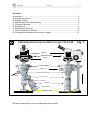
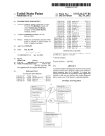
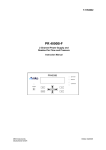
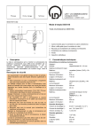
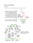
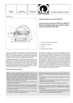
Cathodoluminescence-Microscope
HC5-LM
User and Service Manual
October 2009
No 1019
lumic
www.lumic.de
lumioc - special microscopes Dr. Maria Simon-Neuser- Plasshofstrasse 11, 44795 Bochum, Germany
HC5 LM
Manual
- 1-
Contents:
Introduction ..............................................................................................................2
A Starting the device ...............................................................................................3
B Sample change ...................................................................................................5
C Adjustment of the electron beam ........................................................................6
D Change of filament ..............................................................................................7
E Switching off ........................................................................................................9
F Maintenance and care .........................................................................................9
G Hints for taking CL-pictures ...............................................................................10
H Consumption material and sources of supply ...................................................11
Cathodoluminescence-Microscope HC5-LM
Fig. 1
HC4-LM
tellan-lens
basis-microscope
analyzer
sample chamber
deflection coils
prechamber with flanges
10
to turbo pump
focussing coil
5 [cm]
polarizer
0
electron gun
LED lamp house
grounding cable
We cannot exclude any error and change in this manual.
#1019
HC5 LM
Manual
- 2-
Introduction
The cathodoluminescence microscope HC5-LM enables excitation of luminescence
on the surface of a polished thin section by electron bombardment. This luminescence is dependent on the material characteristics of the excited solid (chemistry,
crystal structure, lattice defects and others). To avoid electrical charging of the samples, they must be coated with a conductive layer. This may be either a gold or carbon coating.
The geometry of this microscope implies that the luminescing surface is observed
from backside, through the sample holder and the whole thickness of the thin section.
This means that, especially with fine-grained samples, the quality of the observed
image can be improved by lowering the thickness of the thin section (< 25 µm). The
quality of the observed and taken image can be largely increased by polishing both
sides of the thin sections (i.e. the backside is polished before fitted to the glass).
As the device works in part with dangerous high voltages it has to be operated
with extreme care by skilled personnel. Maintenance and care of the device
should be accomplished likewise very conscientiously.
This manual includes the following schematic drawings:
Fig. 1: Basic components of the CL microscope .............................................1
Fig. 2: Vacuum-pumping system .....................................................................3
Fig. 3: Casing for low and high voltage supplies with sub-racks ....................4
(3.1) Vacuum control and power supplies for coils (top-rack)
(3.2) Power supply for the electron gun (central-rack)
(3.3) High voltage power supply (base-rack)
Fig. 4: Internal view of the sample chamber ...................................................5
Fig. 5: Internal view of the electron gun ..........................................................7
Fig. 6: Change of filament ...............................................................................8
Figures 2 and 3 show numerical markings, referred to in the text. In the schematics of
the casing for the power supplies the controllers and measuring devices of each subrack are marked with the figure number and additional characters in the respective
drawings (e.g. 3.1a for the main switch of the casing). This combination of figure
number and character will be used throughout the manual to designate the specific
devices.
Hint:
Sample movement in the chamber is done with the brass knurls at the backside of
the chamber. Observation of the thin section sample in the vacuum chamber can be
done using transmitted light, crossed polarizers and CL. Take care that at CLobservation the analyzer is extracted (absorbs too much light).
The power supply of the lamp house has a quick-off switch (on the right front) for a
fast change between CL and transmitted light (with going CL). Only at bright CL
emissions you may wish to switch off the CL in transmitted light too (the CL-shining
may bother). HV is turned off using key 3.3a at the HV-Power supply and turned on
again when returning to CL mode.
HC5 LM
Manual
A
Starting the device
A1
Switch on the external plug board (switch lights up).
- 3-
WARNING: Before turning on the plug board it is absolutely necessary to
check the earth connection, especially the cable between the microscope
stand and the contact at the power supply rack (3.2a)!
A2
For inserting the thin section raise the microscope head completely and carefully take off the cover of the sample-chamber. (The cover is sucked at vacuum
and loose when vented). Take care that the lead glass window does not touch
the objectives and avoid any dirtying of the sample chambers rubber seal and
seat.
A3
Insert the thin section with its upper side down; the span-springs must not be
strained (see Fig. 4). Put on the sample chamber cover.
A4
Check the on/off switch of the rotary pump DS 302 (2b) (should always be on).
Now turn on the vacuum system (2a). The rotary and the turbo pump start and
the fan of the turbo pump runs.
Fig. 2
VARIAN
0
Turbo
primary
pumps
1
VARIAN
*
COUNTERS
MEASURES
LOW SPEED
START/STOP
*
1
0
*
VARIAN
DS 302
Turbo-V 301-AG
A5
The vacuum meter in the power supply rack (3.1d) indicates growing vacuum
by changing to lower pressures. Maximum speed of the turbo pump is reached
at 58 Krpm (digital indication at the pump stand).
Wait until the vacuum pumps will have reached working vacuum within the
sample chamber is reached (from ca. 5x10⁻⁴ mBar) and the color of the small
number "1" in the vacuum meter has shifted from red to green, indicating that
the vacuum is close to ready and the high voltage can be activated (presets of
the vacuum meter must not be changed).
Note: If the device is started after an out of operation period you should continue evacuating for at least 30 minutes before going on (enhances quality of
vacuum and enables function of measuring tube).
HC5 LM
A6
Manual
- 4-
Turn on main switch (3.1a) of the casing for the power supplies (HC5LM-SG):
red switch lights up.
Fig. 3
Power Supply Rack HC5-LM
HC5-LM/SG
3.1a
V
V
0
5,0
-4
1
mbar
3.1
925 micropirani
Vac. only
1
Mains
Deflection
Focus
Beam
3.1b
3.1c
3.1d
3.2e
HC5-LM/EQN
A
3.2a
Filament On
+
Filament
Wehnelt
3.2c
3.2d
3.2
Filament current
3.2b
Never operate without connected groundcable !
Heinzinger
HV Input
LNC 20000-3neg
On / Off
!
3.3b
On / Off
mA
Current
3.3a
KV
3.3e
Voltage
3.3
HV
HV/Output
max. 14 kV
3.3c
3.3d
#1019
A7
Be sure that the toggle switch "Ext./Int." at the digital outlet of the high voltage
power supply (3.3) is set to “Int” (prefixed). (For further information see
"Heinzinger" manual).
At a vacuum value of ca. 5x10⁻⁴ mBar vacuum is ready (number "1" at the vacuum measuring device glows green), the power supplies for the cathode (3.2)
and the high voltage (3.3) are automatically activated. Now the "Power"-LED (at
3.3a) of the "Heinzinger" power supply (rack 3.3) glows orange. Switch on the
high voltage by first pressing the key "On/Off" (3.3a, "Power"-LED changes to
green) and then "HV On/Off" (3.3e, red LED lights up). The cathode now is at
high voltage (14 kV max.! potentiometer 3.3d).
A8
Now the filament current may be adjusted. For starting the Wehnelt knob 3.2d
should be at values around 300 (fine adjustment may be done later, see chapter
C2).
Turn on the filament power supply (3.2e). Now, while watching the sample
through the microscope tube (with 5x objective), slowly turn potentiometer 3.2c
HC5 LM
Manual
- 5-
to the right, until the desired intensity of luminescence is achieved. The left
meter of the high voltage power supply (3.3c) should indicate a starting value of
up to 0.2 mA, and, depending on the sample´s CL can be decreased or increased (pre-adjusted max. current of 0.45 mA should not be exceeded). The
meter for the filament current (3.2b) then should indicate a value of < 1,6 to 2.7
A (this value decreases with increasing age of the filament).
Too high filament currents may overheat the sample and break it.
A9
If the spot by the electron beam is inhomogeneous, the beam has to be adjusted additionally (see chapter C).
___________________________________________________________________
B
Sample change
B1
Turn off the electron beam: First switch off the high voltage by pressing the button HV On/Off (3.3e); the red HV LED light dies. Then turn down the filament
current (potentiometer 3.2c to its leftmost position) and switch off the power
supply for the electron gun (switch 3.2e).
B2
Turn off the vacuum pumps (2a). The pumps stop and the device is completely
vented after about 2 minutes.
B3
Raise the microscope head completely and carefully take off the cover of the
sample chamber. If it cannot be removed, it will take more time to wait until the
chamber is vented and the cover is loosely. When removing the sample chambers cover, do not let the lead glass window touch the objectives and avoid any
dirtying of the sample chambers rubber seal and seat.
B4
Carefully remove the old and insert the new thin section upside down (with the
Fig. 4
Sample Chamber
Sample holder
holder with
with
Sample
holder stage
stage below
below
holder
Aperture
Span-springs
sample side towards the electron beam coming from below) without straining
the span-springs. Put on the cover of the sample chamber.
B5
Start the vacuum pumps (2a) and proceed as described in A5 - A9.
HC5 LM
Manual
- 6-
___________________________________________________________________
C
Adjustment of the electron beam
A proper adjustment of the beam current is between 0,1 and 0,4 mA (meter 3.3c
of the high voltage power supply). It can be changed by varying the filament
current; i.e. the temperature of the filament, with the potentiometer 3.2c.
The beam current limit value is preset to 0,45 mA. (This is revisable by pressing
the button “Preset” (3.3b) to the left of the display; usually there is no need to
change. If the max. beam current is increased to values much higher than
0,45 mA, the thin section may be damaged by overheating!)
You may recognize the response of the current limitation by the just lighting up
of its yellow indicator LED (diode left to the potentiometer 3.3c). Current
threshold must not response during standard operation, as in that case
the accelerating voltage does not reach its rated value.
High voltage is pre-adjusted to 14 kV and normally should not be changed. If
temporarily another (only lower!) accelerating potential is required it may be adjusted by the voltage potentiometer (3.3d) of the high voltage power supply.
The high voltage value during standard operation is 14 kV. Higher acceleration potentials must not be used, as this may damage the unit and
would not be an advantage in observation anyway. Additionally, at bad
vacuum flash-overs inside the electron gun could occur.
C1
To optimize the luminescing spot on the sample following tunings should be
done while regarding carefully both, the sample and the measuring devices:
Moving the luminescing spot to the right or left:
By changing the voltage of the two deflection coils (Fig. 1) the electron beam
can be moved to the right or left side. Voltage of the coils is tuned by potentiometer 3.1b of the power supply for the coils; common values are about 8.
C2
Homogenization of the electron beam:
This can be obtained by changing the voltage of the Wehnelt aperture. Tuning is
done with the potentiometer 3.2d of the power supply (EQN) for the electron
gun (standard position is about 300 on the scale of the potentiometer).
Turn the knob 3.2d until the beam spot is homogeneous at maximum intensity.
The scale of knob 3.2d should be at values between 200-600 then.
These settings have to be re-adjusted with increasing age of the filament
and also at every filament change.
C3
Focusing of the electron beam:
Varying the voltage of the focussing coil (Fig. 1) results in contracting and expanding of the beam. Standard value is about 12 V, it is tuned with the potentiometer of the power supply for the focusing coil (3.1c).
Caution! Too strong contracting of the electron beam may cause partial
overheating of the sample and could result in a damage of the thin section. At worst case, the vacuum window of the sample chamber cover
might break.
HC5 LM
Manual
- 7-
___________________________________________________________________
D
Change of filament
The filament (hot cathode) is subject to wear and break, dependent on the
quality of the vacuum and cleanness of the samples. Typically, it burns out
after 10 to 30 hours of running and has to be replaced. A fused filament can be
recognized by both lack of luminescence and indication of 0 A at the meter for
the filament current 3.2b (see Fig. 2 for the construction of the electron gun).
Tools, used for the change of filament are: hexagon hole Allen wrench 1.5 mm,
tweezers, not fluffing cotton glove (all contained in provided small box).
D1
Turn off the electron beam: At first turn off the high voltage by pressing the button HV On/Off (3.3e). The red HV LED light dies. Then turn down the filament
current potentiometer (3.2c) to the left to stroke.
For safety reasons be sure to turn off the main power supply switch (3.1a)
- the light of the switch is extinct.
D2
Stop the vacuum pumps (2a) and wait for about 2 minutes until the system is in
air.
D3
Keep hold of the upper part of the electron gun and remove the lower part by a
short turn to the left of the bayonet joint (see Fig. 5). Pull out the lower part
without touching the upper part with the Wehnelt cylinder. If the change of filament takes place during a working session, the hot gun has to cool down a bit.
Fig. 5
Electron Gun
bayonet joint
internal thread
external view
to microscope
filament
anode
wehnelt cylinder
adjusting ring
cross
section
filament socket
Important:
The internal parts of the electron gun must not be touched with your fingers. Always use the not fluffing cotton gloves supplied. Soiling the gun
results in problems with the vacuum and increasing wear of the filaments.
HC5 LM
Manual
- 8-
D4
Unscrew the Wehnelt cylinder (counterclockwise) while holding the adjusting
ring (Fig. 6a) in its position .
D5
Pull out the broken filament from the socket with a tweezers. Carefully insert the
new filament with the tweezers. The filament has to be inserted tightly and has
to be pressed closely to the teflon seating (Fig. 6b).
a
Fig. 6
b
c
D6
Carefully screw the Wehnelt cylinder clockwise over its base until it softly contacts the adjusting ring. Primarily, this ring should not be moved.
Correct position of the Wehnelt is achieved, when the tip of the filament can just
be seen within the aperture of the Wehnelt cylinder at a viewing angle of about
45〫(Fig 6c).
A necessity to readjust the height of the Wehnelt, may be indicated by
- lack of adjustability Wehnelt voltage when turning the Wehnelt knob (3.2d),
or
- poor CL emission together with low current voltage.
Poor emission and weak current voltage are indicative of a too high situated
Wehnelt cylinder, whereas lack of adjustability occurs when the tip of the filament reaches too high, that means the Wehnelt is situated too low.
Readjustment of Wehnelt height to its correct position (see Fig. 6c ) is done by
turning the adjusting ring to the respective direction and bringing the Wehnelt
again into soft contact to it until the position of the filament is right.
D7
Take care that the tip of the filament is situated right in the centre of the
aperture of the Wehnelt cylinder to obtain maximal homogeneity of the
electron beam. If the tip of the filament is strongly out of center, it might be useful to put it into its socket the other way round.
D8
Put the electron gun back to its casing and close the bayonet joint.
D9 Evacuate and engage the device according to the instructions of A4 - A9. Wait
at least 15 minutes before turning on the electron beam.
HC5 LM
Manual
- 9-
___________________________________________________________________
E
Switching off
E1
According to the paragraph of sample change take out the sample and close
the sample chamber (B1 to B4) .
Evacuate the device (switch 2a at the turbo rack). If the CL is in daily use, you
should keep it under vacuum permanently, over the weekends too. The pumps
are made for sustained continuous operation.
Only if the device is not operated for a longer period of time, pumps can be
switched off.
E2
Turn off main switch (3.1a); light is off.
E3
Switch off the external plug board.
___________________________________________________________________
F
Maintenance and care
Cleaning of the vacuum-chamber
The internal parts of the cathode device, which work with high vacuum conditions
(sample chamber, electron gun etc.), must not be touched with fingers. Use nonfuzzing cotton gloves. Fouling at the internal surface may contaminate the vacuum
system completely and thus worsen the vacuum and support the consumption of
filaments.
The Wehnelt cylinder within the electron gun (compare Fig. 5) should be cleaned to
shining with chrome polish (WENOL or similar) at about each tenth change of filament. For dismantling see chapter D. Tools for cleaning are cotton swaps (cosmetic
tips), small wooden pins and cloths. Scratching or grinding tools like screw or knife
must not be used at all.
After polishing the cylinder has to undergo ultrasonic cleaning with acetone for about
10 minutes to remove the remaining fat and wax. Ultrasonic cleaning should be once
repeated with fresh acetone.
The large O-ring seal of the vacuum chamber should be cleaned occasionally and
thinly coated with vacuum grease. From time to time the leaded glass in the cover of
the sample chamber should be cleaned with a soft paper soaked with acetone.
Leaded glass is distinctly softer than normal glass; so do not use any scraping tools.
After longer time of running a layer of dirt may have deposited on the brass parts of
the sample stage and the aperture (compare Fig. 4). To remove this coating, the
sample holder can be taken off and ultrasonically cleaned with acetone (for about 10
minutes). The sample holder stage has not to be dismantled, clean it with cotton
swaps soaked in acetone.
If the aperture in the bottom of the sample chamber is strongly polluted (which will
occur after very long time of running only), it can be dismantled with the delivered
special tool. To reach the aperture, first remove the sample stage:
After taking off the sample holder turn the right grub screw as far as possible out of
HC5 LM
Manual
- 10 -
the sample holder stage (the stage moves towards the left). Screw off the long guideway and take off the stage. Loosen the clamp of the long thread and the milled screw
and put the long threat slightly towards the outer side. Now the aperture is accessible
and can be dismounted and cleaned as described above.
Maintenance of the vacuum pumps:
The rotary pump always must be filled with oil according to the manufacturers instructions. Regular change of oil is important. For details see the manuals of the
manufacturer (Varian) in the document folder.
If the pumping device does not reach its final vacuum, this may be due to a leak.
Check at first the seals of the sample chamber and of the electron gun. Even indiscernible fouling or injury of the o-ring seals may drastically reduce the quality of the
vacuum.
___________________________________________________________________
G Hints for taking CL-pictures
Take off the monocular tube by loosening the brass screw and mount the CCDcamera (with the already attached C-mount adapter).
Switch on the PC and wait for about one minute until the IP-addresses are fixed.
Start the Kappa Camera Control (KCC) from the notebook's or the PC´s desktop and
proceed as described in the Kappa manual.
White balance has to be done at transmitted light mode; color temperature of the
LED is suitably for CL too.
HC5 LM
Manual
- 11 -
___________________________________________________________________
H
Consumption materials and sources of supply
Filaments Agar, A 054 for CAMBRIDGE/LEICA
PLANO W Plannet
Ernst-Befort-Str. 12
35578 Wetzlar
Germany
Tel. :+49 (0) 6441 97650
Fax: +49 (0) 6441 976565
eMail: [email protected]
Vacuum system:
Rotary pump:
Rotary vane fluid, GP type (1l), No. 9499390
Oil mist eliminator DS No. 9499395
Oil filter replacement cartridge
No. 9499394
Ordering address for vacuum components and support
Varian, Inc.
via F.lli Varian 54
10040 Leini, (Torino), Italy
Tel.: (39) 011 997 9 111
Toll-Free: 00 800 234 234 00
Fax: (39) 011 997 9 350
Hours: 08:00 to 18:00 Central European time
[email protected]
[email protected]
Measuring coil and switching device:
MKS Denmark ApS
Ndr. Strandvej 119G
DK3150 Hellebaek
Phone: +45 44 92 92 99
[email protected]