1
4. REPLACEMENT OF MAIN COMPONENTS
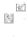
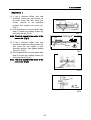
under cover. (Fig.4)
[Installation]
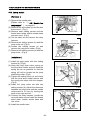
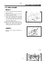
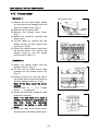
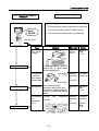
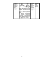
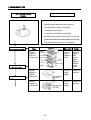
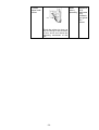
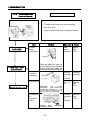
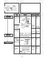
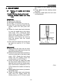
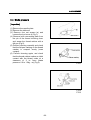
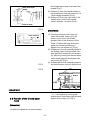
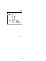
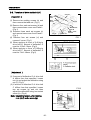
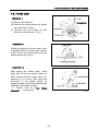
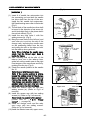
(1) Insert A of needle bar reciprocator into
the connecting rod and also the needle
bar drive shaft from the top of the arm.
Install the felt, needle bar reciprocator,
felt B and bearing case collar in that order.
(Fig.1)
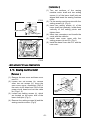
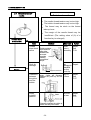
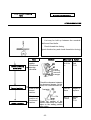
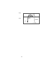
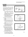
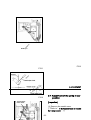
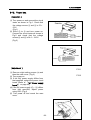
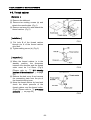
(2) The set hole of the needle bar drive shaft
is turned in the direction of set screw (a)
and it binds tight firmly in the place where
the set hole suited. (Fig.2)
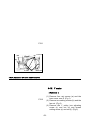
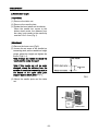
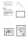
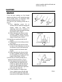
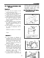
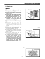
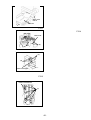
(3) Install the arm front cover L with five
setting screws (b). (Fig.3)
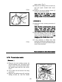
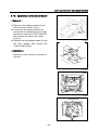
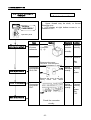
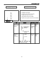
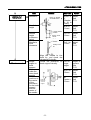
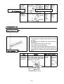
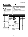
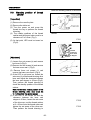
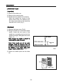
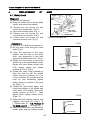
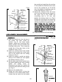
(4) Bring the case linear to the left end, and
cam roller pin is put into the slot of the
change cam, imposing the needle case
on the positioning board from the top,
and putting the slot on the take-up lever
into the take-up lever guide rail.
Note: When installing the needle case,
check that the thread wiper hook is
inside the Velcro.
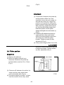
(5) After checking that all the slits of the
take-up lever are in the take-up lever
guide rail, set the needle case to the right
most stopper of the case linear and fix by
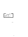
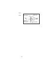
pushing from the top. (Fig.4)
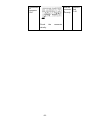
(6) Check the needle position at the needle
No.15.
Note: No play with the needle case.
Note: If the needle position is wrong,
loosen the setting screw for the change
base and adjust the needle position by
moving the needle case right and left.
The change base must be located in the
position where the cam roller pin does
not touch also in the front and back.
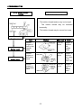
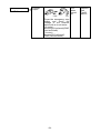
(7) Install the tension base set with two
setting screws (a). (Refer to Fig.3 of
removal)
(8) Install the sensor arm with two setting
screws (b). (Refer to Fig.3 of removal)
Note: Check the position of the sensor.
[Please refer to 『 “ 3-11. Thread
sensor” 』 on page 34 ]
(9) Install the change cover and the relay
card cover with two setting screws.
(Refer to Fig.2 of removal)
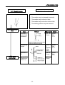
(10) Install the tension base set, upper cover,
-46-
Needle bar
drive shaft
Felt
Needle bar
reciprocator
Set hole
Connecting
rod
A
Felt B
Bearing
case collar
FIG.1
Arm upper
surface
(a)
Set hole
FIG.2
(b)
Arm front cover L
FIG.3
Upper cover
Case linear
Stopper
Under cover
FIG.4