1
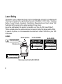
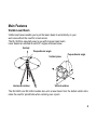
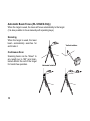
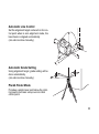
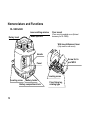
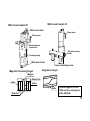
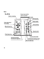
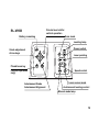
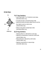
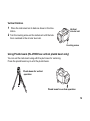
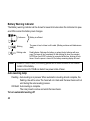
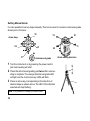
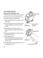
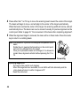
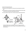
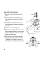
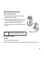
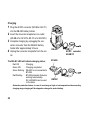
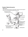
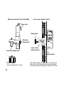
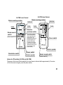
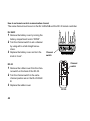
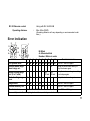
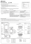
INSTRUCTION
INSTRUCTION MANUAL
MANUAL
ROTATING LASER
ROTATING
LASER
Declaration of Conformity
Model Number:
Trade Name:
Responsible party:
Address:
Telephone number:
RL-VH3G/A/B
TOPCON CORPORATION
TOPCON LASER SYSTEM, INC.
5758 West Las Positas Blvd., Pleasanton,
CA 94588, U.S.A.
925-460-1300
This device complies with Part 15 of the FCC Rules, Operation is subject to the
following two conditions: (1) This device may not cause harmful interference, and
(2) this device must accept any interference received, including interference that
may cause undesired operation.
Foreword
Thank you for purchasing the Topcon RL-VH3G/A/B Rotating Laser.
It is one the world’s most advanced lasers.
To quickly and effectively use the RL-VH3G/A/B, please read these brief
instructions carefully, and keep them in a convenient location for future reference.
Handling Precautions
1 Vibration and Impact Protection
When transporting the instrument, provide protection to minimize risk of severe vibration
or impact. Severe vibration or impacts may affect beam accuracy.
2. Laser Scanning Interference
Particular reflective surfaces such as mirrors and some glass surfaces, can cause beam
reflection that in very rare circumstances can interfere with the laser scanning function. If
this should happen, simply change the location of the laser or cover the reflective surface.
Caution:
Use of adjustment controls or performance procedures other than those specified herein
may results in hazardous radiation exposure.
1
Safety Information
In order to ensure the safe use of this product, prevent any danger to the operator or others,
or damage to property, important warnings are placed on the product and inserted in the
instruction manual.
We recommend that you become familiar with the meaning of these Warnings and Cautions
before continuing.
Display
Meaning
WARNING
Ignoring or disregard of this display may lead to death or serious
injury.
CAUTION
Ignoring or disregard of this display may lead to personal injury or
physical damage to the instrument.
Injury refers to hurt, burn, electric shock, etc.
Physical damage refers to damage to equipment and structure or furnishings.
2
Safety Precautions
WARNING
• There is a risk of fire, electric shock or physical harm if you attempt to disassemble or repair the instrument yourself.
Repairs are to be carried out by TOPCON or an authorized dealer ONLY!
• Laser beams can be dangerous and can cause eye injury if used incorrectly.
Never attempt to repair the instrument yourself.
• Laser beams can be dangerous. They can cause eye injury.
Do not stare into beam.
• Risk of fire or electric shock.
Do not use a wet battery.
• May ignite explosively.
Never use an instrument near flammable gas, liquid matter, and do not use in a coal
mine.
• Battery can cause explosion or injury.
Do not dispose in fire or heat.
• Short circuits can cause a fire.
Do not allow a battery to contact other objects when storing it.
3
CAUTION
Use of controls, adjustment to the laser, or the performing of any procedures other than
those specified herein may result in hazardous radiation exposure.
DO NOT allow anyone to work directly in the path of the laser beam.
Always make sure the laser is operating above the height of your crews heads.
Exposure to laser light may cause momentary blindness. Always use caution when operating equipment near a laser.
Do not allow skin or clothing to come into contact with acid from the batteries. If this occurs, wash off with copious amounts of water and seek medical attention.
Damaged or broken carrying cases may fall open causing injury, or damage to the laser.
Do not use a carrying case with damaged belts, grips or latches.
It could be dangerous if the instrument falls off of its mount. Please check that you have
mounted the instrument to the wallmount or tripod securely and correctly.
An unstable tripod can pose a potential risk of injury, or damage to the laser.
Always check that screws or leg locks are tight, and tripod is sitting firmly.
Please note that the tips of tripod can be hazardous, be aware of this when setting up
or carrying the tripod.
Please note that the tips of tripod can be hazardous, be aware of this when setting up
or carrying the tripod.
4
User Precautions
Always wear the protective clothing (safety shoes, helmet, etc.) when operating.
Exceptions from Responsibility
1) The user of this product is expected to follow all operating instructions and make periodic checks of the
product’s performance.
2) The manufacturer, or its representatives, assumes no responsibility for results of a faulty or intentional
usage or misuse including any direct, indirect, consequential damage, and loss of profits.
3) The manufacturer, or its representatives, assumes no responsibility for consequential damage, and
loss of profits by any disaster, (an earthquake, storms, floods etc.).
A fire, accident, or an act of a third party and/or a usage any other usual conditions.
4) The manufacturer, or its representatives, assumes no responsibility for any damage, and loss of profits
due to a change of data, loss of data, an interruption of business etc., caused by using the product or
an unusable product.
5) The manufacturer, or its representatives, assumes no responsibility for any damage, and loss of profits
caused by usage except for explained in the user manual.
6) The manufacturer, or its representatives, assumes no responsibility for damage caused by wrong
movement, or action due to connecting with other products.
5
Laser Safety
This product uses a visible laser beam, and is manufactured and sold in accordance with
“Performance Standards for Light-Emitting Products” (FDA/BRH 21 CFR 1040) or “Radiation
Safety of Laser Products, Equipment Classification, Requirements and User’s Guide” (IEC
Publication 825) provided on the safety standards for laser beam.
As per the said standard, this product is classified as a “Class 3A (IIIA) Laser Product”.
This is a simple product to operate and does not require training from a laser safety officer.
In case of any failure, do not disassemble the instrument. Contact TOPCON or your TOPCON dealer.
Labels
Beam aperture
For RL-VH3A/B
For RL-VH3G
DANGER
DANGER
AVOID EXPOSURE
LASER LIGHT IS EMITTED
FROM THIS APERTURE
Beam aperture
LASER RADIATION
LASER RADIATION
AVOID DIRECT EYE EXPOSURE
WAVE LENGTH 633nm
5mW MAXIMUM OUTPUT
AVOID DIRECT EYE EXPOSURE
WAVE LENGTH 532nm
5mW MAXIMUM OUTPUT
CLASS a LASER PRODUCT
CLASS a LASER PRODUCT
AVOID EXPOSURE
LASER LIGHT IS EMITTED
FROM THIS APERTURE
Beam aperture (Only for RL-VH3A/G)
6
Contents
Foreword ............................................. 1
Handling Precautions ........................... 1
Safety Information ................................. 2
Safety Precautions ............................... 3
User Precautions................................... 5
Exceptions from Responsibility ............ 5
Laser Safety ......................................... 6
Labels.................................................... 6
Contents ............................................... 7
Standard System Components ............ 8
Main Features ..................................... 9
Nomenclature and Functions ............ 12
Preparation For Use ........................... 18
Battery Installation ................................ 18
Instrument Set-up Procedure ............... 18
Using Plumb beam (RL-VH3B has
vertical plumb beam only) .................... 19
Battery Warning Indicator ..................... 20
Auto-leveling lamp ................................. 20
Operation ............................................ 22
Scanning Mode .................................... 22
Continuous scan.................................... 23
Auto Focus (RL-VH3A/G Only) ............. 24
Changing rotation speed ....................... 25
Laser Pointing Mode (stop) ................... 25
Laser Sensor Mode (RL-VH3A/B Only) 26
Plumb Finder Mode .............................. 26
Height Alert function ............................. 27
High Power Mode (RL-VH3G Only) ...... 27
Setting Slopes ....................................... 28
Vertical Beam Alignment ....................... 34
Setting 90° Vertical Layouts .................. 42
Operational Example .......................... 44
Maintaining Power Sources ................ 45
Checking and Adjusting ..................... 48
Horizontal Calibration ........................... 49
Horizontal Rotation Cone Error ............. 52
Vertical Calibration (Upward) ................ 53
Laser Beam (Downward) ...................... 58
Storage Precautions ........................... 59
Standard / Optional Accessories ...... 60
Specifications ..................................... 67
Error Indication .................................... 71
7
Standard System Components
1
2
3
4
5
6
7
8
RL-VH3G/A/B (RL-VH3A/G includes Floor Mount model 6) ................. 1pc.
Magnetic Target .................................................................................... 2pc.
Alignment Target .................................................................................. 1pc.
Wall Mount Model-2C (RL-VH3G/A) or Model-1C (RL-VH3B) .............. 1pc.
*Battery unit ....................................................................................... 1set
Carrying case ....................................................................................... 1pc.
Calibration decals.................................................................................. 1set
Instruction manual................................................................................. 1vol.
Please make sure that all of the above items are in the box when you unpack.
Additional Magnetic Scanning Targets may be included in some markets.
* The following are battery configurations. Included battery configurations very by package.
Rechargeable battery type:
(with Built-in Run/Charge system)
Rechargeable battery (BT-49Q) ......1pc.
Holder (DB-49C) .............................1pc.
AC/DC converter model, AD-9B/7C 1pc.
8
Dry battery type:
Holder (DB-49)................................ 1pc.
D- cell............................................ 4pcs.
Main Features
Visible Laser Beam
Visible beam lasers enable you to put the lasers beam to work directly on your
work area without the need for a level sensor.
The RL-VH3G is especially easy to see with its green laser beam.
Laser beams are emitted at exact 90° angles as shown below.
Vertical
Perpendicular angle
Perpendicular angle
Vertical plane
Horizontal rotation
Vertical rotation
The RL-VH3G and RL-VH3A models also emit a laser beam from the bottom which eliminates the need for plumb bobs when centering over a point.
9
Automatic Beam Focus (RL-VH3A/G Only)
When the target is used, the laser will focus automatically to the target.
(It is also possible to focus manually with operating keys.)
Scanning
When the target is used, the laser
beam automatically searches for
and tracks it.
Vertical rotation
Continuous Scan
Scanning beam can be "drawn" to
any length (up to 180°) and maintained without the aid of the target
for hands free operation.
10
Horizontal rotation
Automatic Line Control
Set the alignment target centered on far control point when in auto alignment mode, the
laser beam is aligned automatically.
(can also be done manually.)
Automatic Grade Setting
Using alignment target, grade setting will be
done automatically.
(can also be done manually.)
Plumb Finder Mode
Provides a plumb laser spot below the rotating head to aid laser set-up over an initial
control point.
11
Nomenclature and Functions
RL-VH3G/A/B
Laser emitting window
Beam aperture
Rotary head
Floor mount
(Floor mount is supplied as an Optional
accessory for RL-VH3B)
Wall mount/dismount lever
(Only used for wall mount)
Handle
Screw for tripod W5/8
Panel
Leveling screw
Leveling screw
Battery holder
Battery compartment lock
12
Floor fixing leg,
rotating type
Wall mount model-1C
Wall mount model-2C
Wall mount hole
Clamp lever
Clamp lever
LOCK
UNLOCK
Mount position
control line
Elevation clamp
knob
Traveling stage
Wall mount hole
Laser mounting screw
Magnetic Scanning Target
Alignment target
Magnet
Datum line
Index
Index
Index
Detector
The blue target is for RLVH3G and the red target is
for RL-VH3A/B.
13
Panel
RL-VH3A
Battery remaining
Grade adjustment
Arrow keys
Circular level vial for
vertical operation
Scan mode
Leveling lamp
Power switch
Laser pointing
Manual focus key
Speed control
Plumb beam key
Auto/manual Grade
Auto/manual Alignment
Laser sensor mode
Auto/manual leveling control
Manual mode lamp
14
Circular level vial for
vertical operation
RL-VH3B
Battery remaining
Scan mode
Leveling lamp
Grade adjustment
Arrow keys
Power switch
Laser pointing
Plumb beam key
(Vertical operation
only)
Auto/manual Grade
Auto/manual Alignment
Speed control
Laser sensor mode
Auto/manual leveling control
Manual mode lamp
15
RL-VH3G
Circular level vial for
vertical operation
Scan mode
Battery remaining
Leveling lamp
Power switch
Grade adjustment
Arrow keys
POWER
Laser pointing
STOP
Manual focus key
ON
MANU
Speed control
Plumb beam key
High power mode
Auto/manual Grade
Auto/manual Alignment
Auto/manual leveling control
Manual mode lamp
16
Arrow keys
Y2
X2
Y1
Arrow keys
Y2, Y1 key functions
• Use to select either Y1 or Y2 direction in auto slope.
(Horizontal rotation only)
• Focussing the laser in manual focussing mode.
• Selecting a direction the beam should move to scan the
X1
floor target in auto line control mode.
(Vertical rotation only)
• Setting Y axis grade in manual slope mode.
(Horizontal rotation only)
X2, X1 key functions
• Selecting either X1 or X2 direction in auto slope.
• Selecting a control direction in auto line control mode.
(Vertical rotation only)
• Moving the laser in manual line control mode.
(Vertical rotation only)
• Selecting X axis direction in manual slope.
(Horizontal rotation only)
17
Preparation For Use
Battery Installation
For battery placement or replacement instructions, see Maintaining Power Sources section,
page 45 .
Instrument Set-up Procedure
Horizontal Rotation
1
Set the instrument on any smooth surface that is
within ±5° of true level. The RL-VH3G/A/B autolevel system will not function if the unit is placed
more that 5° out of level. For best operation, it is
recommended that it be mounted to a tripod or
the Topcon Wall Mount Model 2C (provided).
Slope can be set in both axes, X and Y. See
"Setting Slope" section, page 28 .
Horizontal
Leveling range
18
Vertical Rotation
1
Place the instrument on its back as shown in the illustration.
2
Turn the leveling screw on the instrument until the bubble is centered in the circular level vial.
Vertical
circular vial
Leveling screw
Using Plumb beam (RL-VH3B has vertical plumb beam only)
You can set the instrument using with the plum laser for centering.
Press the plumb beam key to emit the plumb beam.
Plumb beam for vertical
operation
Plumb beam for vertical operation
19
Battery Warning Indicator
The Battery warning indicator will be shown for several minutes when the instrument is powered ON or when the battery level changes.
Continuous
Note
Battery is sufficient.
Blinking
The power is low, but laser is still usable. (Blinking continues until batteries are
dead.)
Blinking order
Dead batteries. Recharge the battery or replace the dry batteries with new
ones.(The laser will turn completely off after blinking for about five minutes.)
NOTE:Even if an AC/DC converter is connected at this time, blinking still continues. Once the power is turned off, the battery remaining display will reset.
• When BT-49Q is used, the blinking period will be short because of the characteristic of the battery.
• Laser sensor LS-70A/B can detect low power state of laser.
Auto-leveling lamp
Flashing : Auto-leveling is in process. When automatic is leveling almost complete, the
flashing rate will be slow. The head will not rotate and the laser beam will not
emit during the auto-leveling process.
ON Solid: Auto-leveling is complete.
The rotary head is active and emits the laser beam.
To turn automatic leveling off
20
To turn OFF the auto-leveling function (manual mode), press the Auto-Manual leveling control pad twice in quick succession. The manual mode indicator light will illuminate. The instrument can be positioned in any direction and the laser beam remains on and the head will
rotate.
IMPORTANT: In manual mode, the laser beam will not shut off if disturbed! To return to Autoleveling mode, press Auto/Manual control pad once.
21
Operation
Scanning Mode
In scan mode, the laser rotates slowly, "searching" for the Magnetic Scanning Target. When
the target is properly placed in the beam path, the laser beam will scan rapidly back and forth
on the target and "track" the target as it is moved in its path.
1 Scanning mode is the default operating mode for the RL-VH3G/A/B. Each time the instrument is turned on, it is in scanning mode. To change when operating, press the Scan
Mode Pad.
2 To initiate target scanning, place the Magnetic Scanning Target in the beam path with the
reflective strips facing toward the laser.
Horizontal rotation
Vertical rotation
Set scanning mode
22
Face the target toward the instrument to start scanning.
3 To stop scanning, remove target from beam path.
Note
• The target must be in the upright position for horizontal scanning use (magnet
on top).
Continuous scan (Scan width can be "Drawn" and held for "Hands free" operation)
Place target in beam path and hold for a moment. The scanning beam will hesitate, then
start again. When the target is removed the beam will hold that scan automatically.
To change the scanning width, move the target left or right after the scan hesitates and the
scanning width will increase.
Scanning hesitates
and starts again.
Move the target left or right within scanning, the scanning width
changes. The scan continues
without target for hands free
scan operation.
To cancel the "Drawn" scan simply:
Place the target for more than one second into the scanning laser beam again.
23
Auto Focus (RL-VH3A/G Only)
When a target is used, the beam will focus automatically at the target.
Manual Focusing (only for RL-VH3A/G)
It is also possible to focus manually with operating keys.
1 Press the manual focus key. The mode changes to manual focussing mode.
LED
The focus distance
remotes.
Manual focus key
The focus distance
becomes near.
2
Arrow keys
Focus can be adjusted manually by pressing upper or lower arrow key.
Note: When the laser beam is not focused, it may not be possible to detect a target.
To cancel the manual focusing mode;
Press the manual focus key again.
Note: When pressing the Auto/manual grade or Auto/manual alignment key, manual focus will
be cancelled.
24
Changing rotation speed
Press either Speed Control pad to change rotation
speed. The right pad increases the rotation speed.
The left pad reduces the rotation speed.
Laser Pointing Mode (stop)
This mode stops rotation and allows the laser beam to
be pointed by manually rotating the head. Press the
mode control pad to select laser pointing mode. Beam
rotation stops in this mode.
Press the rotation speed keys to
increase or decrease rotation
speed.
Laser pointing
Press the laser pointing keys to
move the beam left or right.
Stop Mode;
Press either laser pointing key. Stop mode is enabled,
and the beam stops rotating.
To move the Laser Beam in Stop mode;
Press either laser pointing key. The beam moves in
the direction of the key being pressed.
Pushing the key momentarily moves the beam slightly.
Continuously holding the key down moves the beam
rapidly in the direction of the arrow being pressed.
25
Laser Sensor Mode (RL-VH3A/B Only)
For long range or outdoor applications, the instrument
can be used with an optional electronic laser sensor.
The Topcon models LS-70B or LS-70A are recommended. Press the Laser Sensor Mode Pad. The
beam rotates at 600 rpm in this setting.
LED
Laser sensor mode pad
Plumb Finder Mode
(RL-VH3B has plumb beam for vertical operation only)
Provides a plumb laser spot below the rotating head to aid laser set-up over the initial control
point.
Plumb beam pad
for horizontal rotation
(RL-VH3G/A Only)
26
Plumb beam pad
for vertical rotation
Height Alert function
When auto-leveling is active, this function prevents the instrument from operating if it is disturbed. This insures accurate control. If the unit is disturbed, the elevation should be verified
and reestablished if necessary.
1
To activate the height alert function, depress and hold the left of arrow keys (X2) (see
page 17 ) on the control panel while turning on the instrument by pressing the Power control pad.
2 When this function is active and the unit is disturbed, visible LEDs will rapidly flash.
3 To re-activate auto-leveling and check the beam height, turn the unit off, then on again by
pressing the Power control pad twice. After auto-leveling is complete, check the beam
height to confirm it has not changed.
4 The Height Alert function is now inactive. To re-activate, turn unit off and repeat step 1.
High Power Mode (RL-VH3G Only)
Pressing the high power mode key, the laser power will change alternately.
LED
Note: When the instrument is in Scanning, Auto grade or Auto-line control mode, it is not possible
to use High power mode.
27
Setting Slopes
The laser beam can be sloped in either the X or Y axis (single slope) or both axes (compound slope).
Using the Slope Control pads (see page 12 ), the
beam can be electronically raised or lowered 5
degrees above or below the inclination of the instruInclination of the
instrument
ment. This means that slopes up to 5 degrees can
be obtained if the instrument is set up on a level surface. For slopes greater than 5 degrees, the instruHorizontal
ment must be manually positioned to within 5
degrees of the slope desired.
X axis
Y axis
POWER
∞
STOP
ON
MANU
LOCK
OPEN
Compound slope
Single Axis
28
Dual Axes
Setting automatic grade using the alignment target
Y2
Y2
X1
Arrow keys
X2
X1
Y1
Auto/manual grade
Y1
X2
Grade setting direction
How to set slope
Single axis setting
1
2
Turn the instrument on by pressing the power control pad. Auto-leveling will start.
3
Press one of the arrow keys to set a slope in one of the directions shown above.
The arrow LED of the direction selected will stop flashing and the laser will start scanning
in that direction.
*To change to another direction, press another arrow button after several seconds.
Press the Auto/manual grading pad after auto-leveling is complete. The green Auto/manual Grade LED will light and the 4 red of arrow key LEDs will flash.
29
For Dual axes setting
Press another arrow key for the second direction in less than 4 seconds after pressing the
key for the first direction. (before the laser starts scanning in the first direction, The key
LED for the second direction selected will stop flashing). The laser beam will pre-scan in
each direction to show the directions set.
Note: If an arrow key for a second direction is pressed more than 4 seconds after the first, it won't
be possible to set up a dual axis slope. The laser will return to single slope.
4
Place the alignment target into the scanning beam.
Note:
1) The alignment target must be in the correct orientation. Top and bottom is marked on the
back of the target.
2) For improved slope accuracy, place the alignment target in the center of the scanning
width.
The direction of alignment target
Place the alignment target in the scanning beam.
30
5
Place the target in the scanning beam so the beam travels in the direction of desired
slope.
The scanning beam will "look" for the center of the target.
When the beam comes to the center of the target, the scanning width will narrow, and the
beam will automatically focus.
For Dual axes setting
When dual axes are selected, the second direction repeats procedures 4 and 5.
6
When the alignment target is removed, the laser will be in scanning mode.
To cancel slope settings
Press the Manual Mode pad. The instrument returns to auto-leveling mode.
Operating range error
The range of the grade setting is within ±5 degrees.
When the range has been exceeded, the red LEDs will flash alternately and the rotary
head will return to a horizontal position.
Re-level, and set-up the instrument again.
31
Setting Manual Grade
It is also possible to set up slope manually. This can be used to increase or decrease grade
already set in the laser.
Y2
Y2
X1
Arrow keys
X2
X1
Y1
Auto/manual grade
1
Turn the instrument on by pressing the power control
pad. Auto-leveling will start.
2
Press the Auto/manual grading pad twice after auto-leveling is complete. The orange Auto/manual grade LED
will light and the 4 red arrow key LEDs will flash.
3
Press an arrow key corresponding to the direction of
desired slope as shown above. The LED of the direction
selected will stop flashing.
Note: It is possible to change the laser mode.
32
Y1
X2
Grade setting direction
The manual mode lamp will light.
4
If you want to set a compound slope, repeat steps 2 and 3 for next axis. The LED of the
second direction selected will turn on.
To cancel slope settings
Press the Manual Mode pad. The instrument returns to auto-leveling mode.
Operating range error
The range of the grade setting is within ±5 degrees.
When the range has been exceeded, the red LEDs will flash alternately and the rotary
head will return to a horizontal position.
Re-level, and set-up the instrument again.
33
Vertical Beam Alignment
Vertical Set-Up: Plumb finder mode
Vertical level
vial
Provides a plumb laser spot below the rotating head
to aid in laser set-up over an initial control point.
This mode is used only for vertical set-up.
1
Rotate forward foot out 180°, and center it on the
control point.
2
Use the leveling screws on the rear floor mounts
to bring the bubble to the center of the vertical
level vial.
3
Press the Power Control key to turn unit on.
When auto-leveling is complete, laser beam will
rotate.
4
Make sure the rotating head is straight using the
Manual Alignment mode.
5
Press Plumb beam key.
Confirm that the beam emits straight down centering on the laser beam indication lines of the
front floor mount.
6
34
Set the instrument to the Auto/manual line control
mode.(See page 35 ,40 )
Plumb beam
Laser beam indication line
Leveling screw
Control point
Control point
Auto Line Control: Smart Line mode
This mode provides one person alignment to a far control point.
There are two operating methods shown as follows;
1: Operation by keys at the laser
2: Operation at the alignment target side
Operation by keys at the laser
1
2
Center the alignment target on the far control point.
3
Press either the X1 or X2 key to set scanning for the side of the laser that has the target.
The laser starts scanning and the selected key”s LED will flash.
Press the Auto/manual alignment pad. The green Auto/manual alignment key LED will
light.
Y1
Y2
Y2
X2
X2
X1
Y1
Green LED
Auto/manual
alignment pad
X1
Alignment
target
Control point
35
4
Press either the Y1 or Y2 key to move the scanning beam toward the center of the target.
The beam will begin to move, and will align to the center of the target automatically.
When the beam reaches the center of the target, the scanning width will narrow, and will
automatically focus. The beam can now be moved manually for precise alignment on the
control point. Refer to page 39 “Fine movement of the beam after completing alignment”.
5
When the alignment target is removed, the laser will be in Scan mode. Press the mode
key to return to a rotating beam.
Note: In procedure 3, if you can not distinguish the position of the
beam;
Rotate the unit, keeping the forward leg on the control point,
and look for a reflection from the target.
Once you've placed the beam on the target, if it is allowed to
remain there, alignment will start without pressing the Y1 or
Y2.
Forward leg
Operating range error
The range of line control is ±5 degrees.
When the range has been exceeded, the red LEDs will flash alternately and the
rotary head will return to within 3 degrees of 0°.
Reset the instrument.
36
Operation at the alignment target side
1
Press the Auto/manual alignment key. The green Auto/manual alignment key LED will
light.
2
Press either the X1 or X2 key to set scanning for the side of the laser that has the target.
The laser starts scanning and the selected key's LED will flash.
3
Center the alignment target on the far control point, passing it slowly through the beam.
X2
X2
X1
Green LED
Auto/manual
alignment pad
X1
Alignment
target
Control point
The beam will begin to move, and will align to the center of the target automatically.
When the beam reaches the center of the target, the scanning width will narrow, and will
automatically focus.
37
* The beam can now be moved manually for precise alignment on the control point.
Refer to page 39 “Fine movement of the beam after completing alignment”.
Operating range error
The range of line control is ±5 degrees.
When the range has been exceeded, the red LEDs will flash alternately and the rotary
head will return to within 3 degrees of 0°.
Reset the instrument.
38
Fine movement of the beam after completing alignment
Fine movement of the beam will be possible after completing the alignment.
1
Move the beam slightly to the right or left by moving the target to the right or left.
The beam will move as follows:
The scanning laser moves toward the center direction of the
target in this part.
Index
The scanning laser will stop moving in this part.
Put the target index on the control point.
If the beam requires more movement, repeat procedures 1 and 2.
2
3
To stop the laser from moving, move the target so it centers on the beam.
4
When the alignment target is removed, the laser will be in Scan mode. Press the mode
key to return to a rotating beam.
Put the target index on the control point. If the beam requires further movement, repeat
steps 1 and 2.
39
Manual Line Control (manual vertical beam alignment)
It is also possible to align the laser manually (without the alignment target).
Manual alignment is possible from the following modes; Change rotation speed, Laser
pointing, Level sensor, Scanning and Plumb finder.
1
2
Set the alignment target centered on the far control point.
3
Press either the X1 or X2 key to move the laser as follows:
Press the Auto/manual alignment key twice. The orange Auto/manual alignment key LED
will light.
X2
X2
X1
Orange LED
Auto/manual
alignment pad
Note:
1) When the instrument is in Auto Line Control mode, it is not possible to be in the
Manual Line Control mode.
2) When the instrument is in Manual Line
Control mode, it is not possible to be in
the Auto Line Control mode.
40
X1
X1
Control point
X2
Operating range error
The range of line control is ±5 degrees.
When the range has been exceeded, the red LEDs will flash alternately.
Press X1 or X2 key to cancel the error and set up the instrument again.
41
Setting 90° Vertical Layouts
1
Move the front floor mount leg to its stored
position.
2
Turn the rear floor mount leveling screws to
bring the bubble to the center of the vertical
level vial.
3
Press the Power Control key to turn unit on.
When auto-leveling is complete, the beam will
be emitted.
4
5
Align the beam on the control point.
6
59mm
59mm
Rotate the laser on the front floor mount, and
place the upper plumb beam on the far control
point. Fine adjustment can be done using the
Manual Line Control mode.
Control point
Control point
Move the beam (in the stopping, scanning or
changing speed modes) to the control point.
The beam is 59 mm forward of the center of
the front floor mount leg (in its stored position).
59mm
42
59mm
7
The rotating axis of the laser is directly over the center of the front floor mount leg in its
stored position. Therefore the beam will rotate forward of the control point when the laser
is rotated on the front floor mount leg.
The Off-set however is constant (59mm) from the rotation axis to the beam, so marking a
control point 59mm behind the actual control point will make set-up easy and accurate.
43
Operational Example
44
Maintaining Power Sources
How to replace dry batteries
1
Remove the battery cover by turning the battery
compartment lock to “OPEN”.
2
Remove the old batteries and replace with four (4)
new “D” cell alkaline batteries making sure each is
placed in the proper direction as indicated.
3
Replace the battery cover (DB-49) and turn the knob
to “Lock”.
Note
• Replace all 4 batteries with new ones.
• Do not mix old batteries and new ones.
Battery cover knob
Rechargeable battery
Installing
1
2
Insert the BT-49Q into the DB-49C.
Place the DB-49C firmly into the instrument and turn the battery cover knob to “LOCK”.
45
Charging
1
Plug the AC/DC converter (AD-9B or AD-7C)
into the DB-49C battery holder.
2
Insert the converter receptacle in an outlet
(AD-9B is for AC120V, AD-7C is for AC230V)
3
Complete charging by unplugging the converter connector from the DB-49C battery
holder after approximately 9 hours.
4
Unplug the converter receptacle from the outlet.
The DB-49C LED will indicate charging status;
Red ON
: Charging.
Green ON
: Charging completed.
Green flashing : DB-49C is not connected to
BT-49Q.
Red flashing
: BT-49Q protection feature is
working automatically.
RL-VH3A/B/G can be used
in this state.
DB-49C
AC/DC converter
AD-9B/7C
BT-49Q
DB-49C
Automatic protection feature; In case of overcharge or high or low temperature state exceeding
charging range, charging will be stopped or changed to protect battery.
46
Note:
1) It can be charged while using the laser.
2) The BT-49Q rechargeable battery can be charged when removed from laser.
3) When the BT-49Q rechargeable battery is taken off from the DB-49 battery holder, the
instrument can be used with dry batteries instead of BT-49Q.
Note:
1) Recharging should take place in a room with an ambient temperature range of 10°C to
40°C (50°F to 104°F).
2) The battery source will discharge when stored and should be checked before using with
instrument .
3) Be sure to charge stored battery source every 3 or 4 months and store in a place at 30°C
or below. If you allow the battery to be completely discharged, it will have an effect or future charging.
4) Recharging of the BT-49Q may sometimes be complete within 9 hours because of its remaining capacity.
47
Checking and Adjusting
There are three areas of performance the user should check periodically.
Horizontal Calibration
Horizontal Rotation Cone
Vertical Calibration
The Horizontal Calibration and Vertical Calibration can be easily checked and, in most cases,
adjustments can be made by the user. Horizontal Rotation Cone can be checked by the user,
if an error is found, adjustments must be made by a Topcon service facility.
Attaching the calibration decals
Before calibration, attach the calibration decals to the instrument as shown below. The calibration decal shows the calibration function of certain control pads on the control panel.
Calibration Decals
48
Horizontal Calibration
(1)Checking Calibration
Instrument as seen from above
50m (160feet)
∞
Target
Wall
Panel side
1
Set up a tripod 50m(160ft) from a wall. Mount the instrument on the tripod, facing the X1 toward the wall.
2
3
Turn the unit on and allow auto-leveling to complete.
4
Loosen the tripod screw, rotate the instrument 180
∞
Place a piece of paper on the wall. Detect a laser position on the wall with target and mark it. Turn the instrument off.
degrees.
Note
• When rotating the instrument, avoid knocking it off level or changing
height.
49
5
Turn the unit on again and allow auto-leveling to
complete.
6
Make a new mark (Mb) where the laser beam
strikes the paper.
7
Measure the distance between the first mark (Ma)
and the second mark (Mb). No calibration is neces-
If less than 5mm( 0.2 inches)
No calibration Necessary
X1 laser beam
X2 laser beam
sary if distance is within 5mm (0.2 inches).
8
Repeat procedure for the Y axis.
50m (160feet)
(2) Adjusting Calibration
If the distance between either set of marks is more than 5mm (0.2inches), turn the unit off by
pressing the [START] pad once and using the following procedure. Confirm that unit has shut
off before beginning the procedure.
(In step 2 and 3, use of optional RC-30 remote control can be helpful. See page 64 .)
1 While pressing the [ENTER] key, press the [START] key. This activates the X axis calibration mode. Confirm that the [X] LED is lit.
Repeat Checking calibration steps 1 to 6 without turning the instrument off in the
checking calibration step 3.
50
Center
position
Laser beam
up or down
2
By pressing the right or left Alignment Control pad, move the X2 (Mb) laser beam up or
down until its centered between marks Ma and Mb.
3
4
When the beam is precisely centered, press the [ENTER] key. The [X] LED will flash.
When the flashing stops, the X axis calibration adjustment is made and power is turned
off automatically.
• If the calibration is greater than the adjustment allows, the error LED will
Note
start flashing. If this occurs, contact your Topcon dealer.
For Y axis calibration, turn the unit as instructed in step 1 above then press the X/Y Axis
Selection pad. Confirm that the [Y] LED is lit, then repeat steps 2 to 4 for the Y axis.
Repeat the checking procedure to confirm proper calibration has been made.
51
Horizontal Rotation Cone Error
Perform the following check after completing "Horizontal Calibration" on the previous page.
Minimum about 40m/131ft
Cone error
∞
Wall
A
1
2
3
4
5
6
Datum position
∞
Wall
B
Wall
A
Wall
B
Set up the laser centered between two walls approximately 40m (131ft) apart. Orient the
instrument so one axis, either X or Y, is facing the walls.
Locate and mark the position of the rotating laser beam on both walls using the target.
Turn off the instrument and move the instrument closer to wall A (1m to 2m /3 ft to 6 ft).
Do not change the axis orientation of the instrument. Turn the instrument on.
Again locate and mark the position of the rotating laser beam on both walls using the target.
Measure the distance between the first and second marks on each wall.
If the difference between each set of marks is less than 4mm (5/32 of an inch), no error
exists.
Note
52
• If the error is greater than 4mm ( 5/32 of an inch), contact your Topcon dealer.
Vertical Calibration (Upward)
Perform the following check after completing "Horizontal Calibration" on the previous page.
(1) Checking RL-VH3G/A
1
2
3
4
5
6
Set up the instrument half way between 2
walls a minimum of 40m away from each
other. (The instrument can be facing
either direction X or Y. And no tripod is
used.)
about 20 m
(66ft)
Wall
A
about 20 m
(66ft)
Wall
B
Turn the power switch on.
Place a piece of paper on each wall (A and B).
Mark the horizontal laser positions (Ma and Mb) on each wall using target.
Turn the power switch off. Position the
about 40 m (130ft)
instrument for vertical operation (see
instruction on page 19 ) with the bottom
side directly facing wall A (see illustraWall
Wall
tion). Make sure the unit is level by check- A
B
ing the circular level vial. Use the leveling
screw to adjust if necessary.
Turn the power switch on. (Laser beam
about 1m
should be in scanning mode.)
Mark where the split beam is emitted
from the bottom and top of the instrument
strikes wall A and B. Measure the distance between two marks on each wall (dHa and
dHb).
53
7
Compare the two measurements dHa and dHb. If the difference between the two measurements is less than 2.5mm ( 1/10 of an inch), no adjustment is necessary. Otherwise,
adjust as follows.
(2)Checking RL-VH3B
1
2
3
4
5
6
54
Set up the instrument half way between 2 walls a minimum of 40m away from each other.
(The instrument can be facing either direction X or Y. And no tripod is used.)
about 40 m (131ft)
Turn the power switch on.
Place a piece of paper on each wall (A
and B).
Wall
Wall
Mark the horizontal laser positions (Ma
A
B
and Mb) on each wall using target.
Turn the power switch off. Position the
instrument for vertical operation (see
about 1m
instruction on page 19 ) with the rotary
side directly facing wall A (see illustration). Make sure the unit is level by checking the circular level vial. Use the leveling
screw to adjust if necessary.
Turn the power switch on. (Laser beam
Foot
should be in scanning mode.)
Mark where the split beam emitted from
the top of the rotary head strikes wall A (Ha). Measure the distance (dHa) between marks
Ma and Ha.
7
8
9
Without moving the position of the front foot, pivot the instrument so the rotary head is
now facing wall B.
Mark where the split beam emitted from
the top of the rotary head strikes wall B
(Hb). Measure the distance (dHb)
between marks Mb and Hb.
Compare the two measurements dHa and
dHb. If the difference between the two
measurements is less than 2.5mm (1/10of
about 1m
an inch), no adjustment is necessary. Otherwise, adjust as follows.
55
(3) Adjusting Calibration for RL-VH3A/B/G
Turn the unit off by pressing the [START]
pad once. Confirm that unit has shut off
before beginning the following procedure. (In
step 2 and 3, use of optional RC-30 remote
control can be helpful. See page 66 .)
1
2
about 20 m
(66ft)
about 20 m
(66ft)
Wall
A
Wall
B
Without moving the unit, press the [ENTER] and [START] keys simultaneously.
Press either the right or left key on the Alignment Control pad to move the laser beam up
or down on wall B until the measurement for the distance dHb is the same as the measurement dHa on wall A.
Laser beam
up or down
3
56
When the beam is positioned so the two measurements are the same, press the [ENTER]
key. The [V] LED will flash.
Reference: for RL-VH3G/A Only
After step 3 in adjusting mode, the laser can be focused by pressing the manual focus pad.
4
When the flashing stops, the vertical calibration adjustment is made and power is turned
off automatically.
• If the calibration is greater than the adjustment allows, the error LED will
Note
start flashing. If this occurs, contact your Topcon dealer.
Repeat the checking procedure to confirm proper calibration has been made.
57
Laser Beam (Downward)
Perform the following check after completing "Vertical Calibration (Upward)" on the previous
page.
Checking
1
2
3
4
5
6
7
Place a piece of paper on each wall and measure the datum position in the same manner as
" Vertical Calibration (Upward)" .
Set the laser on its floor mount, with the head
facing wall B.
Turn the leveling screw to bring the bubble to
the center of the vertical level vial.
Turn the power switch on.
about 5 m
Wall
A
Datum position
Wall
B
10 cm
Measure the distance from datum position on
wall A.
Turn the power switch off. Rotate the instrument
180 degrees with the rotary head facing wall A.
(do not move the front floor mount leg)
Turn the power switch on again and level the
instrument.
Measure the distance from datum position on wall B.
When the difference between measurements is less than 2.5mm, the laser position is precise enough.
Note; If difference exceeds 2.5 mm, contact your dealer or Topcon.
58
Datum position
Storage Precautions
Always clean the instrument after use.
Use a clean cloth, moistened with a neutral detergent or water. Never use an abrasive
cleaner, ether, thinner benzene, or other solvents.
Always make sure instrument is completely dry before storing. Dry any moisture with a
soft, clean cloth.
59
Standard / Optional Accessories
Wall mount-2C
This is used to attach the instrument to wall molding or metal studs. Grip wall angle/molding or screw to studs and tighten the attachment screw securely.
Mount position control line
To be matched with lower mount side
Wall mount hole
Clamp handle
LOCK
UNLOCK
Traveling stage
Scale
To be met with the laser beam
of mount position control line
when the instrument is
adjusted to 0 wall mount unit.
Traveling
quantity
Adjust screw
Adjusting the inclination of
wall mount unit.
Use the right side scale for RL-VH3A/B/G.
Fine movement knob
To be used when the coarse movement knob positions at (0) mark
60
Up
Down
Wall mount hole
Note :Always tie a ceiling wire through the laser handle and secure to a fixed object as a safety
precaution to prevent the laser from getting knocked or loosened from its position and to
the floor.
How to mount /dismount the
instrument
Mount/Dismount lever
1)Set the floor mount hole on the traveling stage hook and slide the instrument
downward.
2)To dismount, press the mount/dismount lever while sliding the laser
upward.
Coarse movement knob
Indicating the knob as follow
↑ LOCK: Fixing the traveling stage
〇 Fine movement
〇 UNLOCK:Coarse movement
(When you unlock this knob, traveling stage will be free. To avoid dropping the instrument, hold instrument by its handle.)
61
Wall mount model-1C (For RL-VH3B)
Laser sensor holder model 5
160
159
Clamp lever
158
157
156
155
154
153
152
151
Clamp knob
150
Elevation
clamp knob
131
139
138
Laser mounting screw
Laser sensor
holder model 5
137
136
135
134
133
132
131
Laser sensor
130
129
128
127
126
125
Clip on target
Used for gripping girder or ceiling
62
Holder Model 5 allows the laser sensor to be moved up or
down on the staff by squeezing the spring-loaded clamp
on its back side without removing the sensor from the staff.
LS-70B Laser Sensor
Beam receiving window
Indicator
Indicator
LS-70A Laser Sensor
Beam receiving window
Index
Buzzer sound
switch
(Quite/Loud/OFF)
Index
Index
Index
Detective
precision switch
Two leveling precision
options are available,
normal precision and
high precision. By
pressing this switch, the
precision options are
switched alternately.
Confirm the precision
choice by the indicator.
(Normal precision is set
when turning on the
power switch.)
Power switch
Buzzer speaker
Illumination switch
Power switch
Buzzer speaker
Buzzer sound switch
(Quite/Loud/OFF)
Auto-cut off function (LS-70A and LS-70B)
The power will be turned off automatically if no laser beam is detected within approximately 30 minutes.
(To turn the sensor on again, press the power switch.)
63
RC-30 Remote control
Laser Power Switch (Standby mode)
Transmission lamp
Battery warning lamp
for RC-30
Stop beam control
Speed control
Pressing this switch for more than three
seconds puts laser in standby mode,
allowing the user to conserve battery
power. If laser remains in standby mode for
2 hours, laser will turn off automatically.
Mode switch control
(RL-VH3G does not have
Laser sensor mode.)
Manual focus control
( Only for RL-VH3A/G)
Alignment control
Slope mode /
X/Y axis selection
X/Y axis lamp
64
Press this key for more than three seconds
to set slope mode or select X or Y axis.
Description of RC-30 functions
Laser power
Pressing for more than three seconds turns laser standby mode on or
off. Laser turns off if standby mode continues for two hours.
switch
(Standby mode)
Transmission
This lamp will indicates a signal is being transmitted by the RC-30.
It should illuminate any time a control pad is pressed.
lamp
Battery warning
Battery warning for RC-30.
Replace the batteries with new ones.
lamp for RC-30
Stop beam control Sets Stop Beam mode and moves laser.
Speed control
The rotation speed of the rotary head can be changed.
Alignment control Moves beam up or down (horizontal rotation).
Moves beam right or left (vertical rotation).
Indicates axis selected during beam sloping operation.
Laser Power
Turns laser standby mode on or off by pressing this key for more than
three seconds.
switch
(The laser will be turned off automatically if the standby mode is contin(Standby mode)
ued for 2 hours)
Mode switch
Laser mode is switched alternately as follows.
Scan mode / Laser sensor mode / Laser pointing mode.
control
Manual focus
Laser beam can be focused manually.
(RL-VH3G/A models only)
control
X/Y axis selection Sets slope mode by pressing for more than three seconds.
Select X or Y axis for manual grading.
To cancel the slope mode press this key for more than three seconds.
X/Y axis lamp
65
How to set remote control communication channel
The same channel must be set on the RL-VH3G/A/B and the RC-30 remote controller.
RL-VH3C
1
Remove the battery cover by turning the
battery compartment lock to “OPEN”.
2
Turn the channel switch to set a channel
by using with a small straight screwdriver.
3
Replace the battery cover and turn the
knob to “Lock”.
Channel
switch
RL-VH3G/A/B
Channel
switch
RC-30
Turn the channel switch to the same
channel position set on the RL-VH3G/A/
B.
3
Replace the rubber cover.
901
78
2
456
Remove the rubber cover from the channel switch on the back of the RC-30.
23
1
RC-30
66
Specifications
Accuracy
Upright
instrument
Laydown
instrument
Horizontal rotation
±10"
Vertical laser beam (Upward)
±15"
Vertical laser beam (Downward)
±0.5mm/1m
Vertical rotation
±15"
Horizontal laser beam (Forward)
±10"
Horizontal laser beam (Backward)
±0.5mm/1m
Auto-leveling range
:
±5°
Measuring range
Range of visible laser beam * Note1)
Horizontal, Vertical (When scanning)
Radius approx. 50m (164ft)
Laser beam spot (Upward)
Radius approx. 50m (164ft)
Laser beam spot (Downward)
Radius approx. 5m (16.4ft)
Note1)The distance of visible laser beams are not constant due to the
brightness of the surroundings.
Using with LS-70A/70B
(RL-VH3A/B Only)
:
Diameter 2 to 500 m ( 6.6 to 1640.5ft)
Light source
:
L.D (Visible laser)
Wave length
:
633nm (RL-VH3A/B)
:
532nm (RL-VH3G)
67
Rotation speeds
RL-VH3A/B
:
Changeable : 30 to 600 r.p.m.
Level sensor mode : 600 r.p.m
When scanning : 80 r.p.m
RL-VH3G
:
Changeable : 30 to 300 r.p.m.
When scanning : 80 r.p.m
:
Maximum 180°
Operation distance
:
3 to 50 m ( 9.8 to 164ft)
Head angle range
:
±5°
Scanning width
Line control
Accuracy (from side to side in the index center)
:
3 to 5m : ±1mm
:
5 to 50m : ±1mm + 10" (3mm/50m)
Operation distance
:
3 to 50 m ( 9.8 to 164ft)
Accuracy
:
3 to 5m : ±1.5mm
:
5 to 50m : ±1.5mm+10" , (3.5mm/50m)
:
Single axis : ±5°
Dual Axes : ±5° (Compound slope)
:
±15’
:
4 D-cell batteries (DC6 V), Rechargeable battery BT-49Q
Slope setting
Range
Plumb finder mode
Accuracy
Power supply
68
Continuous operating time (+20°C)
Alkaline manganese dry batteries
RL-VH3A/B
:
Approx. 40 hours
RL-VH3G
:
Approx. 30 hours
Rechargeable battery BT-49Q
RL-VH3A/B
:
Approx. 30 hours
RL-VH3G
:
Approx. 20 hours
Tripod screw
:
Flat and dome head type, 5”/8 × 11threads
Operating temperature
:
-20°C to +50°C (-4°F to +122°F)
RL-VH3A/G
:
214(L) × 167(W) × 259.5(H) mm
[8.4 (L) × 6.6(W) × 10.2(H) in]
RL-VH3B
:
193.5 (L) × 167(W) × 259.5(H) mm
[ 7.6(L) × 6.6 (W) × 10.2(H) in]
RL-VH3G
:
3.0 kg [6.6 lbs] (without batteries)
RL-VH3A
:
2.5 kg [5.5 lbs] (without batteries)
RL-VH3B
:
2.3 kg [5.1 lbs] (without batteries)
Dimensions
Weight (with Holder DB-49C)
69
Width and diameter of visible beam
Distance
Width of visible
beam *Note
Horizontal, Vertical
(When scanning)
Diameter of
visible beam
*Note
Diameter of laser
beam spot
(Upward)
1m
(3.3ft)
5m
(16.4ft)
10m
(32.8ft)
30m
(98.4ft)
50m
(164ft)
0.5mm
1.0mm
1.5mm
3.5mm
5.0mm
RL-VH3G
0.5mm
1.0mm
2.0mm
5.0mm
8.5mm
RL-VH3A/B
0.5mm
1.0mm
2.0mm
6.0mm
10.5mm
1.5mm
8.0mm
_____
______
______
Diameter of laser beam spot
(Downward)
Note The distance of visible laser beams are not constant due to the brightness of the surroundings.
The above data except Downward beam spot is the values when the laser beam is focused.
Datum laser position
Upright
:
Laydown
:
211mm±1mm
115.6mm
115.6mm
211mm±1mm
70
RC-30 Remote control
Using with RL-VH3G/A/B
Operating distance
:
Max. 90m (295ft)
(Operating distance will vary depending on environmental conditions.)
Error Indication
2
9
7
1
10
8
4
B: Blink
A: Alternate blink
Number: Blinks in order
6
3
5
LEDs
Tilt system error
1
2
3
4
5
6
7
8
9
10
B
B
B
B
B
B
B
B
B
B
Vertical beam alignment range err.
Slope setting range
err. (X or Y axis)
A
Y err.
Auto-leveling range
over
1
3
2
Height alert
B
B
B
Internal memory err.
Mechanical err.
A
Setup the instrument and try to
align the beam again.
A
X err.
Setup the instrument again and try
to set slope again.
Setup the instrument again.
Turn OFF and ON again.
B
Laser beam blinks.
Countermeasures
Turn OFF and ON again.
Turn OFF and ON again.
Turn OFF and ON again.
If errors still persist after attempting to clear them, contact your dealer or Topcon.
71
72
TOPCON CORPORATION
75-1 Hasunuma-cho,Itabashi-ku,Tokyo,174-8580 Japan Phone:3-3558-2520 Fax:3-3960-4214
TOPCON POSITIONING SYSTEMS, INC.
5758 West Las Positas Blvd., Pleasanton, CA 94588, U.S.A.
Phone: 925-460-1300 Fax: 925-460-1315 www.topcon.com
TOPCON CALIFORNIA
3380 Industrial Blvd, Suite 105, West Sacramento, CA 95691,
U.S.A.
Phone: 916-374-8575 Fax: 916-374-8329
TOPCON MIDWEST
891 Busse Road, Elk Grove Village, IL 60007, U.S.A.
Phone: 847-734-1700 Fax: 847-734-1712
TOPCON EUROPE B.V.
Esse Baan 11, 2908 LJ Capelle a/d IJssel, The Netherlands.
Phone: 010-4585077 Fax: 010-4585045 www.topconeurope.com
TOPCON BELGIUM
Preenakker 8, 1785 Merchtem, Belgium
Phone: 052-37.45.48 Fax: 052-37.45.79
TOPCON DEUTSCHLAND G.m.b.H.
Halskestr. 7, 47877 Willich, Germany.
Phone: 02154-9290 Fax: 02154-929-111 Telex: 8531981 TOPC D
TOPCON S.A.R.L.
89, rue de Paris 92585 Clichy, Cedex France.
Phone: 01-4106 9494 (MEDICAL) 1-4106 9490 (TOPOGRAPHIE)
Fax: 01-47390251
http:// www.topcon.co.jp
TOPCON (GREAT BRITAIN) LTD.
HEAD OFFICE
Topcon House Kennet Side, Bone Lane Newbury Berkshire RG14 5PX
U.K. Phone: 001-44-1635-551120 Fax: 001-44-1635-551170
TOPCON SINGAPORE PTE. LTD.
Alexandra Distripark Block 4, #05-15, Pasir Panjang Road, Singapore
118491
Phone: 2780222 Fax: 2733540 E-mail: [email protected]
TOPCON AUSTRALIA PTY. LTD.
408 Victoria Road, Gladesville, NSW 2111, Australia
Phone: 02-9817-4666 Fax: 02-9817-4654
TOPCON INSTRUMENTS (THAILAND) CO., LTD.
77/162 Sinn Sathorn Tower, 37th Fl.,
Krungdhonburi Rd., Klonglonsai, Klongsarn, Bangkok 10600 Thailand.
Phone: 662-440-1152~7 Fax: 662-440-1158
TOPCON INSTRUMENTS (MALAYSIA) SDN. BHD.
Lot 226 Jalan Negara 2, Pusat Bandar Taman Melawati,
Taman Melawati, 53100, Kuala Lumpur, Malaysia.
Phone: 03-4079801 Fax: 03-4079796
TOPCON KOREA CORPORATION
2F Yooseoung Bldg., 1595-3, Seocho-Dong, Seocho-gu, Seoul, 137-876,
Korea.
Phone: 82-2-2055-0321 Fax: 82-2-2055-0319 www.topcon.co.kr
TOPCON OPTICAL (H.K.) LIMITED
TOPCON ESPAÑA S.A.
2/F., Meeco Industrial Bldg., No. 53-55 Au Pui Wan Street, Fo Tan Road,
Shatin, N.T., Hong Kong
HEAD OFFICE
Phone: 2690-1328 Fax: 2690-2221 E-mail: [email protected]
Frederic Mompou 5, 08960, Sant Just Desvern Barcelona, Spain.
TOPCON CORPORATION BEIJING OFFICE
Phone: 93-473-4057 Fax: 93-473-3932
Room No. 962 Poly Plaza Building, 14 Dongzhimen Nandajie,
MADRID OFFICE
Dongcheng District, Beijing, 100027, China
Avenida Ciudad de Barcelona 81, 1 Planta 28007, Madrid, Spain.
Phone: 10-6501-4191~2 Fax: 10-6501-4190
Phone: 91-552-4160 Fax: 91-552-4161
TOPCON CORPORATION BEIRUT OFFICE
Phone: 031-261250 Fax: 031-268607 Telex: 21414
P. O. BOX 70-1002 Antelias, BEIRUT-LEBANON.
TOPCON SCANDINAVIA A. B.
Phone: 961-4-523525/961-4-523526 Fax: 961-4-521119
Industrivägen 4 P. O. Box 2140 43302 Sävedalen Sweden.
TOPCON CORPORATION DUBAI OFFICE
Phone: 031-261250 Fax: 031-268607 Telex: 21414
Offce No. 102,Khalaf Rashd AI Nayli Bldg., 245 Abu Hail Road, Deira,Dubai,UAE
Phone: 971-4-696511 Fax: 971-4-695272
RL-VH3G/A/B
31321 9003
(A)
0001
(1a)