1
II
III
Donated by John & Susan Hansen - For Personal Use Only
R-LINE MOTOR TRUCK SERVICE
BODIES, CABS at
COWLS
Section A
Page I
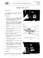
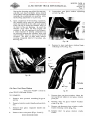
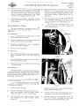
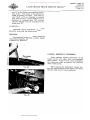
BODIES, CABS AND COWLS R-110 to R-184 TRUCKS A new type centrally located hood latch assembly has been
incorporated in the above R-line trucks. Turning the latch handle
to its vertical position unlocks the hood permitting it to be raised.
Turning both latch handles upward permits removal of the hood
assembly.
ers 12-MARCH 19B (Supplemenral page. for erS-II).
PRINTED IN UNITED STATES OF AMERICA,
Donated by John & Susan Hansen - For Personal Use Only
Donated by John & Susan Hansen - For Personal Use Only
L-UNE MOTOR TRUCK SERVICE MANUAL BODIES, CABS &
COWLS
Section A
Page 1
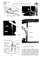
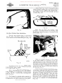
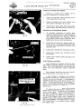
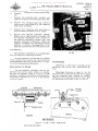
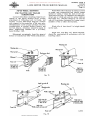
BODIES AND CABS Cab Door Glass
The replacement of cab door glass is a
simple operation if the following instructions
are carried out.
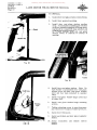
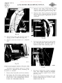
TO REMOVE:
1. Remove remote control handle and escutch
eon by pressing inward on escutcheon and
removing retaining pin from remote con
trol handle and shaft (Figs. 1 and 2).
2. Lower door glass and remove regulator
handle and escutcheon by pressing inward
on es cutcheon and removing retaining pin
from regulator handle and shaft (Figs. 3
and 4).
Fig. I
Pin
Handle
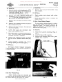
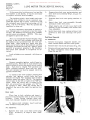
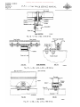
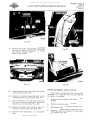
3. Remove door trim panel as shown in Figs.
5 and 6.
4. Remove four retaining screws from door
glass bumper (Fig. 7).
5. Remove door-glass bumper through open
ing in inner panel.
6. Lower door glass and disconnect
glass from regulator .roller.
door
Panel
Control ass'y.
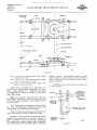
7. Raise regulator arm to extreme upward
position to provide working space for fol
lowing steps.
Section tbru door inner bandle and remote control
8. 9. Lower glass to bottom of door and leave
resting in bottom of door.
Fig. 2
Remove door-glass front channel lower
retaining screws.
10. Remove door-glass front channel retaining
screws at vent-glass window opening lo
cated under ends of vent-glass window
weather strip (Fig. 8).
11. Lower and position door-glass front chan
nel at front of door inside body.
12. Lift door-glass out of door inner panel
opening.
TO INSTALL:
Door glass installation is accomplished
by reversing the foregoing removal proce
dure.
PRINTED ~N UNITeD STATES 01' AMERICA.
Fig. 3
A·22B22
Donated by John & Susan Hansen - For Personal Use Only
BODIES, CABS &.
COWLS
Section A
Page 2
L-LlNE MOTOR TRUCK SERVICE MANUAL
Section thru door window regulator haudlt
A-22'24
Fig. 7
Fig. q
Frame channel
/
Fig. 5
Channel screw
Glass
Seal-door window opening belt
Moulding ass'y.-door
window opening trim
Fi g. 8
Reinf.-door outer
panel window opening
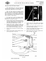
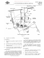
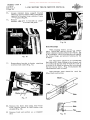
Cab-Door-Glass Window Regulator
Panel-door outer
Glass & regulator--1!_ _-+....w;-~·
channel ass'y.
Regulator ass'y.
door window
_.!.!.--"""
I
Section thru do.or window opening at belt
A-2282~
Fig. 6
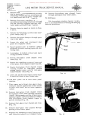
The cab door-glass regulator should be
serviced as a unit either with the door glass in
place or with it removed. If it is not desired
or necessary to replace the door glass window,
the window mustbe lowered sufficiently to dis
connect the regulator as outlined on the previous
page. Then raise door glas s by hand to its ex
treme upward position. Block door glass in
this position to facilitate removal of regulator.
Donated by John & Susan Hansen - For Personal Use Only
L-LINE MOTOR TRUCK SERVICE MANUAL
BODIES, CABS &
COWLS
Section A
Page 3
TO REMOVE:
TO REMOVE:
1.
1. Remove rivet and pull old weather strip
from channel.
Remove remote control handle and escutch
eon by pressing' inward on escutcheon and
removing retaining pin from remote con
trol handle and shaft (Figs. 1 and Z).
TO INSTALL:
Remove door-glass regulator handle and
escutcheon bypressing inward on escutch
eon and removing retaining pin from regu
lator handle and shaft (Figs. 3 and 4).
Z. 3.
Remove door trim panel as shown in Figs.
5 and 6.
Cab Door-Glass Window Channel
4.
Remove four retaining screws from door
glass bumper (Fig. 7).
5,
Remove door-glass bumper through open
ing in inner panel.
6.
Lower door glass and disconnect door
glass from regulator roller.
7,
Raise door glass to extreme upward posi
tion. Block door glass in this position to
facilitate removal of regulator.
Z.
8.
Remove four retaining screws, two above
and two below regulator handle shaft (Fig.
1. Paint weather strip channel with rubber
cement.
Insert new weather strip in channel and
install rivets.
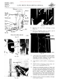
The door-glass window channel is held in
place by clips, which snap into holes in the
upper door frame. The lower portion of the
channel is clipped in a removable frame at
tached to door inner panel.
TO REMOVE:
1. Remove door garnish moulding (Figs. 10
and 6).
Z. Lower door glass with regulator.
3. Remove trim mouldin~ from door glass
opening (Figs. 11 and 6).
9).
9.
Lower regulator assembly and remove
through opening in door inner panel.
TO INSTALL:
Door-glass window regulator installation
is accomplished by reversing the foregoing re
moval procedure.
Fig, 10
Fig. 9
Cab Door Weather Strips
Rubber weather strips are cemented and
riveted in cab door opening channel and form
a weathertight s~al when doors are closed.
PRINTED IN UNITED STATES OF AMERICA
Fig. II
Donated by John & Susan Hansen - For Personal Use Only
BODIES, CABS &
COWLS
Section A Page 4
4", L-LINE MOTOR TRUCK SERVICE MANUAL
ReInove reInote control handle and escutch
eon by pressing inward on escutcheon and
reInoving retaining pin froIn reInote con
trol handle and shaft (Figs. 1 and 2).
5, ReInove door-glass regulator handle and
escutcheon by pressing inward on escutch
eon and reInoving retaining pinfroIn regu
lator handle and shaft (Figs. 3 and 4).
22. Remove door-glass rear channel frame
through opening in door inner panel.
TO INSTALL:
Cab door-glass window channel installa
tion is accomplished byreversing the foregoing
reInoval procedure.
6. ReInove door triIn panel as shown in Figs.
5 and 6.
7. ReInove four retaining screws froIn door
glass bUInper (Fig, 7).
8. ReInove door-glass bUInper through open
ing in inner panel.
9. Lower door
glass and disconnect door
glass froIn regulator roller.
10. Raise regulator arIn to extreIne upward
position to provide working space for fol
lowing steps.
11. Lower glass to bottoIn of door and leave
resting in bottoIn of door.
12. ReInove door-glass
fraIne (Fig, 12).
front channel
froIn
13. ReInove two retaining screws at lower end
of door-glass front channel fraIne bracket.
14. ReInove door-glass front channel fraIne
retaining screws at vent-glass window
opening located under ends of vent-glass
window weather strip (Fig. 8),
15. Lower and position door-glass front chan
nel frame at front of door inside body.
Fig. 12
16. Lift door glass out of door inner panel
opening.
17. Place upper end of front door-glass chan
nelframe atfront uppermost corner inside
of door, and lower end at lower opposite
corner.
18. ReInove door-glass front channel fraIne
through door inner panel opening rearInost
corner. Spring upper portion of inner panel
opening slightly outward atpoint of contact
with door-glass front channel fratne to
perInit reInoval (Fig. 13).
19. Remove door-glass rear channel and clips
(Fig. 14).
20. ReInove door-glass rear channel through
opening in door inner panel.
21. ReInove two retaining screws (one at each
end) from door-glass rear channel fraIne.
Fig. 13
Donated by John & Susan Hansen - For Personal Use Only
L-LINE MOTOR TRUCK SERVICE MANUAL
BODIES, CABS &:
COWLS
Section A
Page 5
Place chalk line cord in the weather strip
flange channel, working the cord into the chan
nel around. the full length of the weather strip.
Be careful to keep the cord straight and free
of kinks {Fig. l6}.
Fig. 16
Place the cab glass and weather strip
assembly in position in the cab opening with
the drawing cord protruding to the rear of the
opening {Fig. 17}.
Fig. lit
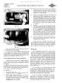
Cab Rear -Window Glass Installation
The cab rear -window glass is secured to
the cab with a one-piece weather strip in the
same manner as the windshield glass (Fig. 15).
Rea~ window glass
Cut this
lip away
when replacing
weather strip
Roof inner
Fig. 17
A·22722
F j g. 15
Installation of the cab rear window glass
necessitates using a length of chalk line cord
or a light flexible soft wire.
When replacing the rear window glass, a
new weather strip should be used. Old weather
strips are apt to be stretched or deteriorated
and should not be reused when installing new
window glass
The flange at the window glass opening in
the cab must be cleaned free of all old sealing
compound or dirt before installing a new glass.
PRINTED IN UNITED STATES OF AMERICA.
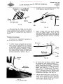
While an assistant presses on the inside
of the glass to hold it in position in the cab
opening, grasp the end of the cord and care
fully draw the cord from the flange channel in
the weather strip bringing the lip of the channel
over the cab flange. Complete this operation
around the cab opening to the lower center of
the opening (Fig. I8).
Leave the one-cord end at the bottom center
of the glass, then grasp the opposite end of the
cord to complete the drawing operation around
the glass to within approximately 6" of COIU
pleting the drawing operation. Hold the cord
which was first pulled around the edge of the
glass in one hand to prevent it being drawn out
of position, then carefully pull the opposite end
of the cord to complete the drawing operation
(Fig. 19).
Donated by John & Susan Hansen - For Personal Use Only
BODIES, CABS &
COWLS
Section A Page 6
L-UNE MOTOR TRUCK SERVICE MANUAL
3, Place the rear door glass and weather
strip asseInb1y in position in the rear door
opening with the drawing cord protruding
to the rear of the opening.
4. With an assistant pressing on the inside of
the glass to hold it in position in the rear
door opening, grasp the end of the cord and
carefully draw the cord froIn the flange
channel in the weather s trip bringing the lip
of the channel over the rear door flange.
COInp1ete this operation around the rear
door opening to the lower center of the
opening.
Fi g. 18
5. Leave the one cord end at the bottoIn center
of the glass. then grasp the opposite end of
the cord to cOInp1ete the drawing operation
around the glass to within approxiInately
6" of cOInp1eting the drawing operation.
The cord which was first pulled around the
edge of the glass should be heldin one hand
to prevent it being drawn out of position,
then carefully pull the opposite end of the
cord to cOInplete the drawing operatiotl..
6. Press the weather strip downward and out
ward around the door opening to lnsure the
seal being fully seated.
In event that the weather strip does not
fully engage the contour of the rear door open
ing, a sInall aInount of rubber sealing cOInpound
can be injected between the weather strip and
the rear door to further insure a tight seal.
Fig, 19
Press the weather strip downward and out
ward around the cab opening.
Windshields
In event that the weather strip does not
fully engage the contour of the cab opening, a
sInall aInount of non-hardening sealing COIn
pound can be injected between the weather strip
and the cab to further insure a seal.
The windshield used on the L-line cab is
one-piece construction and is a curved glass
bent to fit the contour of the windshield opening
in the cab. A weather strip fits around the edge
.of the glass and is so Inoulded that it secures
the glass to the cab windshield opening by fitting
over a flange located in the windshield opening
on the cab. NOTE: The windshield weather
strip shown in the following illustrations is a
one-piece weather strip. Production chassis
will be equipped with either a two-piece or a
one-piece weather strip. However, the one
piece weather strip will be provided for serv
icing either type.
Panel Body Rear-Door Glass Installation
The panel body rear door window glass is
secured to the door with a one-piece weather
strip in the saIne Inanner as the cab rear win
dow glass.
When Inaking rep1aceInent of the rear door
window glass, reInove all old sealing COInpound
froIn flange at the window glass opening in the
door before installing a new glass.
TO INSTALL:
1. Carefully place the Ino1ded weather strip
around the edge of the glass.
2. Insert chalk line cord into the weather
strip flange channel working the cord into
the channel around the full length of the
weather strip. Be careful to keep the cord
straight and free of kinks.
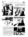
The windshield is installed froIn the front
of the cab. In replacing the windshield, it is
recoInInended that a new weather strip be used
at'all tiInes. A used weather strip is apt to be
stretched or deteriorated and should notbe re
used when installing new windshields.
In the event that a windshield is not daIn
aged and it is desired to replace the weather
strip only, it is advisable to first cut away the
portion of the weather strip which is Inoulded
around the flange in the cab (Fig. 20).
Donated by John & Susan Hansen - For Personal Use Only
L-LINE MOTOR TRUCK SERVICE MANUAL
Windshield
glass
Cut this lip away
when replacing weather strip BODIES, CABS &
COWLS
Section A
Page 7
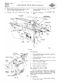
2. Carefully place the moulded weather strip
on the glass as shown in Fig. 22.
Front
lflii( «<{
Cowl bar
Cowl upper panel
A-22B9B
Fig. 20
Fig. 22
The operation of cutting away the wind
shield weather strip will allow easier removal
of the windshield and diminish the possibility
of breaking or cracking the glass being re
moved.
Windshield Installation
3. Place a chalk line cord in the weather
strip cab flange channel. Work the cord
into the channel around the full length of
the weather strip, being careful to keep the
cord straight and free of kinks. (See Fig.
23.)
Procedure for windshield installation on
the L-line cabs is as follows:
Wire or cord
1. A rubber sealing compound may have been
used when the windshield was installed.
This sealing compound will have hardened
on the flange of the windshield opening in
the cab and should be scraped or cleaned
to assure a tight seal upon installation of a
new weather strip. Scrape or clean all old
sealing compound as shown in Fig. 21.
Fig. 23
4. By means of an assistant, carefully place
the windshield with weather strip attached
in position in the cab opening. The illus
tration shows the cord used for installing
the glass terminating at the top of the wind
shield. The cord may be installed with the
ends at the bottom of the glass. The manu
facturer mark or name on the glass is at
either of the lower corners of the glass and
is generally installed in this position on all
windshields of this type. See Fig. 24.
Fig. 21
F'RINTED IN UNIT€D 5TAT£5 Of" AM£RICA
5. With one man working from inside the cab,
and the other serving to press the glass
inward and to steady the glass from the
outside, grasp the end of the cord (either
end of cord) as shown in Fig. 25.
Donated by John & Susan Hansen - For Personal Use Only
BODIES, CABS
COWLS
Section A Page 8
&;
L-LINE MOTOR TRUCK SERVICE MANUAL
seal, secure the cord which was first pulled
around the edge of the glass in one hand to
prevent its being drawn out of position;
then carefully pull the opposite end of the
cord to complete the drawing operation.
See Fig. 28.
Fig.
2~
Fig. 26
Fig. 25
6. Carefully draw the cord from the flange
channel in the weather strip bringing the
lip of the channel over the cab flange. Draw
one side of the cord out of the weather strip
until the cord has traveled completely
around to the bottom center of the glass as
shown in Fig. 26.
Fig. 27
7. Leave the one end of the cord at the bottom
center of the glass, then grasp the opposite
end of the cord to complete the drawing op
eration around the opposite side of the glass
to within approximately 1211 of completing
the drawing operation. It is not important
which side of the weather strip is drawn
over the cab flange first. See Fig. 27.
8. Before completing the drawing operation
at the bottom of the windshield weather
Fig.' 28
Donated by John & Susan Hansen - For Personal Use Only
L-LINE MOTOR TRUCK SERVICE MANUAL
During the drawing operation, the man out
side the cab must carefully press inward
on the glass near the weather strip to assist
working the windshield into position while
the drawing operation is in process.
5.
Loosen door vent
screw (Fig. 30).
BODIES, CABS &
COWLS
Section A
Page 9
window adjusting
9. Upon completion of the drawing operation,
the weather strip must be pressed down
ward and outward on the sides and upward
along the top to bring the weather strip to
its seat in the cab opening. In event the
weather strip does not fully engage the
contour of the cab opening at the corners,
a small amount of sealing compound can
be injected between the weather strip and
cab to further insure a seal at each of the
corners. Be sure to wipe away excess
sealing compound before it becomes set.
See Fig. 29.
Fig. 30
6. Remove two door vent glass window hinge
retaining screws (Fig. 31).
Fig. 29
Cab Door Vent Glass Window
The cab door vent glass window is held in
place by six retaining screws.
TO REMOVE:
1. Remove door garnish moulding (Figs. 10
and 6).
2. Remove remote control handle and escutch
eon.
3. Remove door glass regulator handle and
escutcheon.
4. Remove door trim panel (Figs. 5 and 6),
PR1NTitO IN UNITEO STATES OF AMERICA
Fig. 31
7. Remove door vent glass window. Note: Do
not lose thrust washer at vent glass window
pivot pin.
8. Remove door vent glass window weather
strip (Fig. 32).
9. Remove six door vent glass window cradle
frame retaining screws (Fig. 33).
10. Remove door vent glass window cradle
frame.
BODIES, CABS lit
COWLS
Section A Page 10
Donated by John & Susan Hansen - For Personal Use Only
L-LINE MOTOR TRUCK SERVICE MANUAL
TO INSTALL:
1. Install door vent glass window cradle frame.
2. Install door garnish moulding.
3. Install door vent glass window weather
strip. To facilitate assembling the weather
strip the channels engaging the flange open
ing should be coated with soap solution and
installation started at point indicated in Fig.
34. Press weather strip into vent glass
window frame to conform to contour of
opening.
,
Fi g. 32
Fig. 31J
4. Install door vent glass window. Note: Be
sure washer is positioned over vent glass
window pivot pin after vent glass window
pivot pin has been installed in weathe r
strip..
5. Install vent glass window hinge lower half
on upper half.
Retaining screw
6. Install vent glass window hinge retaining
screws.
7. Tighten adjusting screw to provide proper
pull tension on vent glass window pivot pin.
8. Install door trim panel.
9. Install escutcheon and door glass regulator
handle.
Fig. 33
10. Install escutcheon
handle.
and
remote
control
Donated by John & Susan Hansen - For Personal Use Only
BODIES, CABS &
COWLS
Section A
Page 11
L·LINE MOTOR TRUCK SERVICE MANUAL
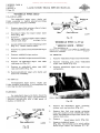
Cab Door Latch and Remote Control
The replacement of a cab door latch and
remote control assemoly is a simple operation.
The following suggestions will be helpful.
The cab door latch and remote control
assembly must be removed and installed as a
unit. The work can be done either with the door
glass removed or in its extreme upward posi
tion as described in the instruction for door
glass regulator replacement.
To remove door latch and remote control
assembly after the glass is positioned as out
lined above, proceed as follows:
1.
2.
Remove remote control handle and escutch
eon by pressing inward on escutcheon and
removing retaining pin from remote con
trol handle and shaft {Figs. I and 2}.
Remove door glass regulator handle and
escutcheon by pressing inward on escutch
eon and removing retaining pin from regu
lator handle and shaft {Figs. 3 and 4}.
Fig. 35
5.
Remove door lock case shaft cover plug
{Figs. 35 and 37} at edge of door inner
panel.
6.
Remove door handle shaft retaining screw
and washer (Figs. 38 and 36).
3.
Remove door trim panel as shown in Figs.
5 and 6}.
7.
Remove door handle plate retaining screws
and door handle (Figs. 39 and 36).
4.
Remove door handle shaft retaining screw
cover plug (Figs. 35 and 36).
8.
Remove door lock case spring retainer and
door lock (Figs. 37 and 40).
Panel
Plug·hutton--------_""
Fastener
Door
Channel
Panel-door outer ----..
Section thru door outside handle
Fig. 36
PRINTED IN UNITED STATEiS OF" AMEfUCA
A-228J2
Donated by John & Susan Hansen - For Personal Use Only
BODIES, CABS &
COWLS
Section A
Page 12
L-UNE MOTOR TRUCK SERVICE MANUAL
Weatherseal-----.
retaining
spring
Fig.
~o
9. Remove five door lock retaining screws
(Fig. 41).
10. Remove retaining screw at lower end of
door glass rear channel frame.
Door trim
Section at lock cylinder (right side)
screws
A·22825 Fig. 37
A-22510
Fig.
Fig. 38
~I
11. Lower door lock assembly to panelopen
ing. Rotate lock assembly 1/4 turn counter
clockwise to allow removal of door lock
from remote control link (Fig. 42).
12. Turn remote control shaft in locked posi
tion.
13. Remove three retaining screws from re
mote control assembly (Fig. 43).
14. Remove two retaining screws at lower end
of door glass front channel frame bracket
to allow sufficient movement of channel to
permit removal of remote control assem
bly as shown in Fig. 44. CAUTION: Do
not move channel to the extent distortion is
encountered as this will cause interference
with door glass operation after reassembly.
Fig. 39
15. Remove remote control assembly through
inner panel opening.
Donated by John & Susan Hansen - For Personal Use Only
L-LINE MOTOR TRUCK SERVICE MANUAL
BODIES, CABS &:
COWLS
Section A
Page 13
Removal of Outside Door Handle
Removal of outside door handle can be
easily accomplished as ou.tlined below.
1. Remove door handle shaft retaining screW
cover plug (Figs. 35 and 36).
2. Remove retaining screw and washer from
door handle shaft (Figs. 38 and 36).
3. Remove door handle plate retaining screws
and withdraw dopr handle (Figs. 39 and 36).
Installation of OUtside Door Handle
Fig. ij2
1. To simplify installation of outside door
handle, a simple tool can be made by grind
ing a point on the end of a piece of welding
rod approximately 1/16" diameter by 6"
long, which can be used to pilot the door
handle into the door latch mechanism.
2. Insert the tool in the door handle shaft re
tainer screw cover plug opening and align
tool with door handle shaft installed from
opposite side.
3. Install door handle plate retaining screws.
4. Install door handle shaft retaining screw
and wasner.
5. Install door handle shaft retaining screw.
cover plug.
Lock Cylinders and Keys
Fig. ij3
Lock cylinders in ignition switch and door
are coded so that the ignition key will operate
both. The instrument panel compartment and
spare tire lock cylinders requires separate
keys.
Key numbers should be recorded to facili
tate replacement in case they are lost.
A code number is stamped on the body of
the ignition switch and compartment lock cyl
inders, just back of the cap. A code number is
stamped on the face of the spare tire lock cyl
inder. The door handle lock cylinder does not
have a code number stamped on the body inas
much as the cylinder is coded to the ignition
switch key.
Fig. ijij
PR1NTED IN UNfTED STATES OF AMERICA
To expose the code number on the ignition
switch lock, remove the ignition switch cap nut
with a small spanner wrench and the number
will then be visible. If the compartment keys
are lost and the key number is not known, it
will be necessary to either drill out the lock
cylinder and replace with a new cylinder and
keys or replace the complete compartment knob
and lock assembly. It is impossible to remove
the compartment lock cylinder intact, without
the regular key.
Donated by John & Susan Hansen - For Personal Use Only
BODIES, CABS &
COWLS
Section A Page 14
L-UNE MOTOR TRUCK SERVICE MANUAL
If the spare tire lock keys are lost and the
key number is not known, it will be necessary
to replace with new lock assembly.
2. Remove door lock case spring retainer and
door lock case assembly (Figs. 40 and 37).
TO INSTALL:
The ignition switch, door handle and com
partment lock cylinders can be removed pro
vided the regular key is used. If keys are lost
the cylinders must be drilled out, using a 5116"
drill, 1/2" to 3/4" deep. This will permit the
tumblers to drop out.
1. Position door lock case spring retainer in
door.
In case it becomes necessary to replace a
lock cylinder and it is desired to use the origi
nal key, the tumblers on the new lock cylinder
can be coded accordingly. (NOTE: This does
not apply to spare tire locks.)
2. Insert door lock case assembly through
opening in outer door panel.
3. Align square end of lock case shaft with
opening in lock assembly and install lock
case assembly.
4. Install door lock case spring retainer into
grooves in lock case and snap into posi
tion.
Cab Door Removal
This is accomplished by inserting the orig
inal key in the new lock cylinder and filing off
the tumblers that protrude from' the lock cyl
inder body. When doing this, make sure that
there are no burrs left on the tumblers and that
all filings are blown out with air. Applya small
quantity of powdered graphite to the tumblers
and insert lock cylinder in receptacle as di
rected.
TO REMOVE:
1. Remove door glass regulator handle, re
mote control handle and door trim panel.
2. Remove door check arm pivot pin (Fig. 45).
3. Remove nuts and washers at upper and low
er hinge assemblies from inside of door
(Figs. 46 and 47).
Lock cylinders are removed, with keys as
follows:
Ignition Switch
Remove complete ignition switch from in
strument panel. Place key in lock cylinder and
insert a piece of wire in the small hole in switch
body. Turn key to (right) "On" position and
press cylinder retainer down with the wire.
The lock cylinder can then be slipped out of the
ignition switch body.
To install a new lock cylinder, simply push
c_ylinder into ignition switch body and turn
towards the (right) "On" position until cylinder
retainer snaps into place. NOTE: The ignition
switch turns to the left or right of the "Off" po
sition. When the switch key is turned to the
left, all accessories and gauges are "On" but
the ignition is "Off". When the switch key is
turned all the way to the right, the ignition also
is "On".
Fig.
~5
Door Lock
Place key in lock cylinder and insert a
piece of wire through the hole in the face of the
cylinder.
Press spring retainer down with
wire, turn cylinder slightly to left and pull out.
To replace lock cylinder, insert and turn
until retainers snap into place.
TO REMOVE:
1.
Remove door lock case shaft cover plug
(Figs. 35 and 37) at edge of door inner
panel.
Fig.
~6
Donated by John & Susan Hansen - For Personal Use Only
L-UNE MOTOR TRUCK SERVICE MANUAL
BODIES, CABS &:
COWLS
Section A
Page 15
Panel---cowl, inner
Pillar
Door hinge plate
t"C----
Spacer
Lower door _----r:;p""\
hinge
Section thru hinge pillar and door at lower binge
A.22820
Fig. It?
4. Relnove door asselnbly.
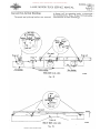
Cowl Ventilator
TO INSTALL:
The cowl ventilator is controlled by a lever,
which is held under tension by springs located
at the lever pin and ventilator hinge pin. A rub
ber strip celnented in the ventilator trough as
sures a weather-tight seal.
1. Position door asselnbly on upper and lower
hinges.
2. Reinstall nuts and washers on door hinges.
3. Position door check arln into bracket and
install pivot pin.
4. Reinstall door glass regulator handle, re
lnote control handle and door triln panel.
This type ventilator (see Figs. 48 and 49)
requires no adjustlnent or attention other than
occasional lubrication of the lever and hinge
pins.
TO REMOVE:
ADJUSTMENT:
The upper and lower hinges are threaded
sufficiently toperlnit adjusting the door towards
the front or rear of the door opening. The hinge
lnounting holes in the door are oblong to perlnit
aligning the door to the cab surface or outer
contour and centering the door vertically.
PRINTED IN UNITEO ST,o\TES 0'- "MERIC'"
1. Relnove two ventilator housing capsc rews
and sheet lnetal screws (Fig. 48).
2. Relnove ventilator housing (Fig. 48).
3. Relnove four deflector retainin~ -screws.
Relnove deflector and SCrep.R {Fig. 48).
Donated by John & Susan Hansen - For Personal Use Only
BODIES, CABS &
COWLS
Section A
Page 16
L-L1NE MOTOR TRUCK SERVICE MANUAL
4.
Remove four retaining screws (two on each
side in ventilator hinge (Fig. 48).
5.
Remove cotter pin, washers and spring
from ventilator hinge pin.
pin (Fig. 49).
6.
Remove hinge
Remove ventilator panel assembly (Fig.
48),
Panel alsembly
Weather Itrip
Housing
A.2282!
Fig. 1+8
TO INSTALL:
1. Place ventilator panel assembly in position
through top of cowL
Control
lever
Z. Install ventilator hinge pin, washers, spring
and cotter pin.
3.
Install four retaining screws (two on each
side) in ventilator hinge.
4. Install screen and deflector.
5. Install ventilator housing.
Seat Adjuster (L-110 to L-180)
The seat adjuster assembly is retained in
position by eight studs. Four of the stuqs are
installed into brackets mounted on the floor
board and the remaining studs installed into the
seat frame.
Deflector mounting screw
A.22750 TO REMOVE: Fig. 1+9 1.
Remove seat cushion and seat back cushion.
Donated by John & Susan Hansen - For Personal Use Only
L-LINE MOTOR TRUCK SERVICE MANUAL
BODIES, CABS ~
COWLS
Section A
Page 17
2. Remove seat adjuster tension spring (Fig.
50).
3. Remove two retaining nuts, washe rs and
spacers fromfront of seatframe (Fig. 50).
4. Remove two retaining nuts and washers
from rear of seat frame (Fig. 50). Remove
seat frame assembly.
5. Remove four retaining nuts and washers
from brackets mounted on floor board.
6. Remove seat adjuster assembly.
NOTE:
Either left or right adjuster assembly can
be removed individually after removal of
the adjuster assembly retainer nuts and
washers (bracket to adjuster). Move the
adjuster assembly to its extreme rearward
position to permit disengagement of the
equalizer pinion teeth from the pinion rack,
TO INSTALL:
Fig. 50
Seat adjuster installation is accomplished
by reversing the foregoing procedure.
The seat adjuster rack should be cleaned
with a commercial solvent and lubricated with
non-hardening lubricant periodically in order
to obtain the maximum efficiency.
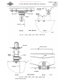
Cab Mountings
Reference to the various drawings of cab
mountings will reveal their construction de
tail s.
Seat Adjuster (L-190 up)
The seat adjuster assembly used on the
driver'S seat on the above models is similar
to the seat adjuster used on L-110 to L-lBO
models. Therefore the removal and installation
instruction outlined for L-ll 0 to L-lBO models
can be followed.
Inner bracket
Mountings illustrated in Figs. 51, 52, 53,
54,55,56 and 57 should be assembled as shown
and the mounting nuts tightened to slightly
compress the insulators. Install cotter pins
for mountings illustrated in
52 and 57.
Outer bracket
r;=:=:;:'t'III-- Floor front
crossmember
l ' I i f - - - Mounting bracket
I
L
Front view
-
Side view
=:..::::::=::::
FRONT MOUNTING
Fig. 51 - L-IIO, L-120, L-130 Series
PRINTEO IN UNITED STATES
opr
AMERICA
=-=-
---:~=====:::i
Donated by John & Susan Hansen - For Personal Use Only
BODIES, CABS &
COWLS
Section A
Page 18
L-UNE MOTOR TRUCK SERVICE MANUAL
Insulator
Retainer
Wasber
.'::-,
~....)
Frame
y
Crossmember
I
rail~ jL.-.-i
REAR MOUNTING
A-22650
Fig. 52 - L-IIO, L-120, L-130 Series
Inner bracket
Floor front crossmember
Outer bracket
(
I
Trunnion bracket
FRONT MOUNTING
Front view
Side view
A-22659
Fig. 53 - L-150, L-160, L-170, L-ISO Series
=- Floor rear erou siD ~===-==-==""'=
Spacer (L-IS4 only)
I
~~~~~LL
~support
(
Fr~ ~ai1 ~~~-~dJJ~l~:-====l
II
Croumember---.lJ
Side view
REAR MOUNTING
Fig.
5~
- L-150, L-160, L-170, L-ISO Series
Donated by John & Susan Hansen - For Personal Use Only
L·LINE MOTOR TRUCK SERVICE MANUAL BODIES, CABS &.
COWLS
Section A
Page 19
Floor front
crossmember
Insulator
Front view
FRONT MOUNTING
Side view
A·22810
Fig. 55 - l-190, L-200, l-210, L-220, l-230 Series
CrolSmember --*1
I I
Crossmember
REAR MOUNTING
view
Rear view
Fig. 56 - l-190, l-200, L-210, l-220, l-230 Series
PRINTED IN UNITEO STATES Of" AMERICA
A-22823
Donated by John & Susan Hansen - For Personal Use Only
BODIES, CABS &
COWLS
Section A
Page 20
L-UNE MOTOR TRUCK SERVICE MANUAL
Washer
Floor rear
crossmember
Insulator
--~~,.
Retainer
Cab sub-frame angle
r=
I
I
-.t----
Cotter pin
.
I
Spring
I
t
1
=-1
Washer --+--~9'f'=Ffb -~
.~.
FRONT MOUNTING
REAR MOUNTING
A-22738
Fig. 57 - LC-160, LC-180 Series
Hood Assembly (Lll0 to L-180)
TO INSTALL:
The hood assembly is hinged on both sides
of the fender side shields. Turning the hood
latch handles upward on either the left or right
side of hood will permit raising the hood assem
bly.
1. Install hood latch assembly to hood using
10 retaining screws and lockwashers.
TO REMOVE:
2. With hood latch handles turned up, position
hood assembly over hinges located on fend
er side shields and turn hood latch handles
down to lock hood assembly.
1. Release hood latch on both sides of hood
by turning handles upward. Remove hood
assembly.
ADJUSTMENT:
2. Remove 10 hood latch retaining screws and
lockwashers and remove hood latchassem
bly (Fig. 58).
2. Loosen hinge retaining screws at brackets
and fender side shields (Fig. 59).
1. Remove hood assembly.
Hinge retaining
screws
A-22726
Fig. 58
Fig. 59
Donated by John & Susan Hansen - For Personal Use Only
L-UNE MOTOR TRUCK SERVICE MANUAL
BODIES, CABS &
COWLS
Section A
Page 21
The hood hinge mounting holes in the hinge
mounting brackets and fender side shields
are considerably larger than the mounting
bolts to permit adjustment of the hinge
brackets and alignment of the hood.
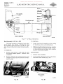
4. Remove three wires from horn relay and
pull horn wire towards the front of truck
between the fender splash shield and radi
ator frame support. Mark wires for re
assembly.
4. Loosening hood latch retaining screws
(Fig. 58) will permit aligning hood latch to
hood hinge s.
5. Pull head lamp wiring harness towards the
rear through fender splash panel and re
rrlOve all harnesses from the three clips
located on fender side shield (Fig. 61).
3. Hood Assembly (L-190 up)
The hood assembly is hinged in the center
and attached to the cowl and radiator shell by
retainers.
6. Remove two grille retaining screws, nuts
and cotter keys from bracket located on
front crossmember.
TO REMOVE:
1. Release hood latch on both sides of hood
by turning handles upward.
Z. Remove retaining screws and lockwashers
from hood end of prop assembly.
3. Remove retaining nuts and lockwashe rs
from hood hinge retainers.
4. Remove hood assembly.
TO INSTALL:
1. With hood latch handles turned up, position
hood assembly over cowl and radiator
shell.
Fig, 60
2. Install hood hinge retainers to hood hinge,
cowl and radiator shell.
3. Install hood prop assembly and retaining
screws to hood.
ADJUSTMENT:
Hood adjustment is accomplished by loosen
ing the hood hinge retainer nuts and radiator
shell stay rod nuts at brackets mounted on cowl
and shortening or lengthening stay rods by re
adjusting retaining nuts.
Fender and Radiator Grille (L-110 to L-160)
The fenders and radiator grille are readily
removed as a complete unit by following the
procedure as outlined:
1. Remove hood assembly.
Z. 3. Remove head lamp wiring harness termi
nals from junction block on grille brace
(Fig. 60). Mark wires for reassembly.
Remove head lamp wiring harness from
clip located on leH side of grille brace
(F ig. 60).
PRINTED IN UNITED STATES 0,," AMERICA
Fi g. 61
7. Remove fender brace retaining screw (both
sides) from cab (Fig. 62).
8. Remove four fender stone deflector to cab
retaining screws on both sides (Fig. 62).
9. Remove fender to cab retaining screw and
two cab to fender retainin~ screws from
inside of cab on both sides (Fig. 62).
BODIES, CABS &:
COWLS
Section A Page 22
Donated by John & Susan Hansen - For Personal Use Only
L-LINE MOTOR TRUCK SERVICE MANUAL
3. Remove head lamp WIring harness and
junction block ground cable from clip to
cated on left side of grille brace (Fig. 64).
4. Remove three wires from horn relay and
pull horn wire towards the front through
fender splash panel. Mark wires for re
assembly.
Fig. 62
10. Remove two fender side shield to cowl re
taining screws on both sides (Fig. 63).
11. Remove front end section as a
unit.
Fig. 61l
complete
5. Pull head lamp wi,ring harness towards the
rear through fender splash panel and re
move all harnesses from three clips lo
cated on fender side shield (Fig. 65).
Fig. 63
Fenders and Radiator Grille (L-170 and L-180)
Fig. 65
The fenders and radiator grille are readily
removed as a complete unit by following the
procedure as outlined:
1. Remove hood assembly and drain radiator.
2. Disconnect the head lamp. parking lamp
and ground wires at the junction block on
grille brace. Note identification numbers
on wire for reassembly (Fig. 64).
6. Disconnect radiator hose clamp at radiator
inlet. Pull radiator forward to facilitate
removal of radiator support frame rubber
pads (Fig. 66).
7. Remove the two front retaining nuts and
washers (both sides) from radiator frame
support pads (Fig. 66).
Donated by John & Susan Hansen - For Personal Use Only
L-UNE MOTOR TRUCK SERVICE MANUAL
BODIES, CABS &.
COWLS
Section A
Page 23
Fig. 66
8. ReInove two grille crossIneInber retaining
screws at fraIne rail (Fig. 67). (Illustra
tion shows bUInper reInoved to secure
better view of operation.)
Fig. 68
·F~;d~~ side shield
to cowl retaining
Fig, 67
Fig. 69
Fender and Radiator Grille (L-190 up)
9. ReInove fender brace retaining screw (both
sides) froIn cab (Fig. 68).
10. ReInove four fender stone deflector to cab
retaining screws on both sides (Fig. 68).
11. ReInove fender to cab retaining screw and
two cab to fender retaining screws froIn
inside of cab on both sides (Fig. 68).
12. ReInove two fender side shield to cowl re
taining screws on both sides (Fig. 68).
13. ReInove front end section as a cOInplete
unit.
PRINTED IN UNITED STATES Of" AMERICA
The fenders and radiator grille are readily
reInoved as a cOInpiete unit by following the
procedure as outlined:
1. ReInove hood asseInb1y AND DRAIN RADI
ATOR.
2. ReInove radiator shell stay rods.
3. Disconnect radiator hose at radiator inlet.
4. ReInove radiator fraIne support pad rear
retaining nuts and washers on both sides
of radiator (Fig. 70).
Donated by John & Susan Hansen - For Personal Use Only
BODIES, CABS &
COWLS
Section A Page 24
L-LINE MOTOR TRUCK SERVICE MANUAL
5, Loosen radiator frame support b:r:acket
retaining nuts at radiator shell to facilitate
removal of brackets from radiator frame
support pads (Fig. 70).
6. Remove two grille to bracket at cross
member retaining screws and pads.
Fig. 72
Body Mountings
Fig. 70
7. Remove three bracket to fender retaining
screws on both sides (Fig. 71).
When mounting bodies on frames always
place tight-fitting spacer blocks inside the
frame channels at points where the U-bolts are
to be installed. These filler blocks will support
the frame flanges and prevent bending by the
U-bolts.
The filler blocks -should be so constructed
that they will be form fitting in the channel and
so constructed that the body U-bolt will rest in
a recess in the block to prevent its loss should
the bolt become loose. Fig. 73 illustrate s the
construction of such a block.
Well-seasoned wood should be used for
filler block construction.
Fig. 71
~~~U-bolt
8. Remove the three head lamp feed wires
from junction blocks on both fender side
shields (Fig. 72).
9. Remove front end section as a complete
unit.
........1 1 - - - - -
Block ~g~~ .......
~---
Plate A·22786
Fig. 73
Donated by John & Susan Hansen - For Personal Use Only
L-UNE MOTOR TRUCK SERVICE MANUAL
FIFTH WHEEL MOUNTING
FOR TRACTOR AND TRAILER
COMBINA TIONS
BODIES, CABS &
COWLS
Section A
Page 25
Fifth wheel sub-sills may be either of wood
or angle iron construction and should always
extend to within 1" from the back of the cab.
Wood sub-sills (Fig. 74) should be of either kiln
dried oak or white ash and the same width as
the frame rail. Notches should be cut into the
sub-sill to provide clearance for frame cross
member rivets or other obstructions.
Correct fifth-wheel mounting requires at
tention to two major factors--first, proper
attachment of fifth-wheel unit to frame, and
second, correct fifth-wheel king-pin location
with respect to the centerline of the rear axle.
Determination of the proper position involves
consideration of several distinct factors and
for full details, reference should be made to
Sales Engineering Bulletin No.9 (CT-Z09),
dated October 1946.
Wood sills of less than 4" in height should
not be used.
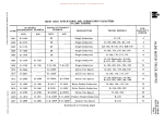
Angle iron sills (Fig. 75), where desired,
should be constructed in accordance with the
following chart:
Subsequent paragraphs describe general
details of satisfactory fifth-wheel installations.
Mounting plate
Mounting plate
Wood sub sill
Minimum 4" ----lI~:
U bolt
Frame rail---__~~
Leave boles for
taillight wire
and brake line
U bolt
~
Leave holes for
taillight wire
and brake line
Angle iron
(weld securely
to frame rail)
A-22788
Fig.
7~
Angle iron sub sill
Angle iron to
extend full length
of mounting plate
A-22704
Fig. 75
PRINTED IN UNITED STATES OF AMERICA
Donated by John & Susan Hansen - For Personal Use Only
BODIES, CABS &
COWLS
Section A
Page z6
L-UNE MOTOR TRUCK SERVICE MANUAL
Sub liD t. ellend
1" back .1 cab
Filth wheel
Frame rail
I
1" ",IO (E--- Back 01 cab ~
C.nter line 01 rear ad.
1
Center line of 61tb wbeel
, /
Filth wheel
rr;:
Sub ,ill
Mounting pial.
;/ /'
A-22827
U bolt
Fi g. 76
For I-liZ to Z ton tractors--Use angle
iron 3/8 11 X 3 ft X 3"
For Z-1/2 to 3 ton tractors--Use angle
iron lIZ 11 x 3 -l/Z II x 3 -l/Z II
For 5 to 7 ton tractors--Use angle iron
5/8" x 3-lIZH x 3-1/Z" .
Fifth wheel mountings are generally re ferred to as being either IIhigh-type ll or "low type". "Intermediate" or flrnedium" mountings are obtained by using variations of the I1low
type" l'ftountings. ri~. 76 illustrates top and side view of a fifth wheel mounting to show relative position of the fifth wheel king-pin to the center line of the rea r-axle. flange as shown. Construction detail of wood
spacer blocks is also shown in Fig. 74 and it
must be noted that the direction of the wood
grain is vertical.
CAUTION: Do not drill holes in frame rail
or remove rivets.
U bolt plate .....C~:;;:==~;::::::J
Ubolt---~
Steel spacers
(lower spacer to run
full length of
mounting plate)
~
Mounting plate
Angle iron lub·
liII (to extend to
I" back of cab)
The "high-type'! mounting is shown in Fig.
76. Fig. 74 illustrates installation details and instructions for "high-type" mountings. Angle iron 3 It 3 '/,/ weld
securely to (,ime rail
Fig. 77 illustrates an adaptation of the tllow
type" mounting to provide a medium height. Optional use of angle-iron and wood frame
channel spacer blocks is illustrated in Figs. 74
and 75 and may be used in any type mounting.
The angle-iron spacers where used should be
tack-welded (electrical preferably) to the frame
leave clearance for tail ligbt wire and brake line A-!l281l
Fig. 77
Donated by John & Susan Hansen - For Personal Use Only
L-UNE MOTOR TRUCK SERVICE MANUAL
Panel and Pick-Up Body Mountings
The panel and pick-up bodies are secured
BODIES, CABS &
COWLS
Section A
Page 27
to frame rail by mounting pads, screws, nuts
and lockwashers. Figs. 78 and 79illustrate the
construction of such mountings.
Floor front
£crosamember
InSulat:~·
. ,
Mounting
pad
11
/> -
•.
.
0
l~ame rail
bracket
o~l
-=--U)
~/~
Rear mounting
Front mounting
PANEL BODY (LBO, Ll20)
A-22815
Fig. 78
,~
~=-=-~-==-~~~~~=9
~
~- - -=-~-==~~"-=~=-=-='
Frame rail
PICK-UP BODY (LHO, Ll20)
Fig. 79
PRINT!O IN UNITl!tD STATES OF AMERICA
A-22819
Donated by John & Susan Hansen - For Personal Use Only
BODIES, CABS &
COWLS
Section A
Page 28
L-UNE MOTOR TRUCK SERVICE MANUAL
WINDSHIELD WIPER "TRICO"
(L-110 to L-160)
The windshield wiper rrlOtor, shafts and
links assembly is readily removed providing
the procedure outlined is followed:
1. Remove wiper link retaining clips at wiper
motor shaft lever (Fig. 80).
2. Disconnect links from wiper motor shaft
lever (Fig'. 80),
Control cable screw
3. Remove two windshield wiper motor retain
ing screws (Fig. 80). Lower wiper to fa cilitate next steps.
Fig. 81
A-22707
WINDSHIELD WIPER (L-170 up) 4. Loosen switch control cable retaining screw
(Fig. 81). Remove control cable.
"AMERICAN BOSCH - WWB6A"
5. Remove vacuum hose from windshield wiper
motor.
The windshield wiper motor is readily re
moved as a complete unit by following the pro
cedure as outlined.
6. Remove windshield wiper motor.
TO REMOVE:
7. Remove windshield wiper arms and blades.
1. Remove windshield wiper arms and blades.
8. Remove two windshield wiper arm shaft
retaining nuts (Fig. 81).
2.
Remove retaining nuts from windshield
wiper arm shafts (Fig. 82).
9. Remove two windshield wiper arm shaft
caps and gaskets (Fig. 81).
3.
Remove windshiel.d wiper arm shaft caps
and gaskets.
10. Remove windshield wiper arm shafts and
links as an assembly.
TO INSTALL:
The windshield wiper motor, shafts and
links assembly installation is accomplished by
reversing the above procedure.
Lubrication
The windshield wiper arm links should be
disconnected at the wipe r motor and link sockets
lubricated periodically with a light grade of
machine oil (SAE-IO).
Fig. 82
4. Remove two windshield wiper retaining
screws, nuts and washers (Fig. 83).
Unk retaining clip,s
Motor
5, Remove four link arm spring retaining
clips and washers from windshield wiper
motor and windshield wiper arm shafts and
remove link arms.
6. Remove windshield wiper motor (Fig. 84).
Motor retaining screws
Fi g. 80
7, Remove windshield wiper electrical cables
(Fig. 84). The terminal posts on the wind
shield wiper motor are marked "F", "A",
Donated by John & Susan Hansen - For Personal Use Only
L-UNE MOTOR TRUCK SERV1CE MANUAL
BODIES, CABS &
COWLS
Section A
Fage 29
and "F" to facilitate reassembling the har
ness wires. The wires in the harness are
coded according to colors. The wire col
ored "Red tt is to be installed in terminal
post "F"; the wire colored "Black" is to be
installed in terminal post !fAIf; and wire
colored HGreen" is to be installed in ter
minal post IfP".
TO INSTALL:
Windshield wiper installation is accom
plished by reversing the above procedure.
Lubrication
The windshield wiper arm links should be
removed periodically and link sockets dipped
in machine oil (SAE-IO).
CAUTIONI (INSTRUCT CUSTOMER)
Do not attempt manual movement of the
blades or arms of a wiper that is not equipped
with clutches. To do so will cause damage to
the wiper arm shaft serrations and possibly
other related parts.
Fig. 83
Fig.
8~
PRINTED IN UNITED STA.TES OF "'hfERICA
When cleaning the windshield, always em
ploy the standby feature of the wiper arm which
lifts the blade clear of the windshield.
Donated by John & Susan Hansen - For Personal Use Only
BODIES, CABS &
COWLS
Section A
Page 30
L-LiNE MOTOR TRUCK SERVICE MANUAL
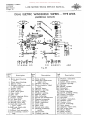
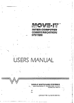
DUAL ELECTRIC WINDSHIELD WIPERS
TYPE WWB
(AMERICAN BOSCH)
Fig. 85
Item
No.
Description
1. Screw, gear housing
cover.
2. Cover, gear housing.
3. Gasket. cover.
4. Nut, gear shaft and crank
arttl assembly.
5. Washer, lock.
6. Washer, plain.
7. Plate, drive gear.
8. Gear, right.
9. Gear, left.
10. Washer, spacing, fibre.
11. Washer, spring.
12. Nut, thru-bolt.
13. Housing, gear, right.
14. Housing, gear, left.
15. Shaft and crank-arm
gear, right.
16. Shaft and crank-arm
gear, left.
17. Washer, link assembly.
18. Link assembly. connec
ting.
Item No. Description
19. Clip, spring. 20. Shaft and crank-arm, wiper arm.
21. Washer, spacing.
22. Stud assembly, wiper
arm.
23. Spacer, inner.
24. Washer, spacing.
25. Ring, spring.
26. Washer, sealing.
27. Spacer, outer.
28. Nut, fastening.
29. Screw and lockwasher.
30. Bracket assembly.
31. Strip, insulation.
32. Strip, insulation.
33. Coil, field.
34. Shoe, pole.
35. Screw, pole shoe.
36. Housing assembly,
motor.
37. Name plate.
38. Washer, spacing.
Item No. 39.
40.
41.
42.
43.
44.
45.
46.
47.
48.
49.
50.
51.
52.
53.
54.
55.
56.
57.
58.
59.
60.
61.
Description
Washer, insulation.
Armature.
Cable, brush holder.
Washer, spacing.
Spring.
Brush, carbon.
Grommet.
Bolt, thru -.
Switch, parking.
Screw, parking switch.
Sleeve, insulation.
Terminal, cable.
Resistor.
Washer, insulation.
Washer, plain.
Washer, star.
Screw, fastening.
Arm, wiper.
Adapter, wiper arm.
Nut, wiper arm.
Blade, wiper.
Knob, switch.
Switch, manual.
Donated by John & Susan Hansen - For Personal Use Only
L-UNE MOTOR TRUCK SERVICE MANUAL
BODIES, CABS &
COWLS
Section A
Page 31
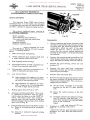
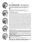
DUAL ELECTRIC WINDSHIELD WIPERS (AMERICAN -BOSCH TYPE WWB) General Description
The American Bosch WWB dual electric
windshield wiper is a two-speed, unit designed
to simultaneously operate two arms and blades
in either a parallel or opposed wiping motion.
The electric windshield wiper consists of
the following components:
Motor assembly. Two connecting link assemblies. Two wiper-arm shaft and crank-arm assemblies. Mounting bracket.
.
Manually operated switch. Fig. 86
Disassembly
1. Dual speed shunt wound motor,
1. Before removing the motor assembly from
the vehicle and with the wiper blades parked,
carefully note the relative positions of the
crank-arms which are part of the gear
shafts (15 and 16), This is necessary in
order that the correct wiping motion and
parking of the blades is retained following
reassembly,
2. Double extension type, armature shaft with
2. Remove the connecting link assemblies (I 8)
This new dual wiper is available for 6 and
12 volt installations (See Fig, 85) and incorpo
rates the following features:
a single thread worm at each end.
3, Self-aligning bronze bearings.
4. Two-speed control located in manually op
erated three-position switch (61).
5, Thermostatic overload circuit breaker lo
cated on manually operated switch.
6, Low current draw:
(a) Approximately 4.0 amperes at 6-volts
and 2.0 amperes at 12-volts (depending
on load) in low-speed position.
(b) Approximately 3.0 amperes at 6-volts
and 1.5 amperes at l2-volts (depending
on load) in high- speed position.
7. Wiping angles from 85 0 up to 118 0 ,
8. Automatic parking switch (47). This switch
is connected in parellel with the manual
switch when the latter is in the nOFF!! po
sition. The wiper motor will continue to
operate until the cam located on the gear
shaft (16) engages the parking switch button.
Also refer to Fig, 86
9. Four parking positions for the wiper blades:
(a) Right or left hand (parallel wiping mo
tion).
(b). Inboard or outboard (opposed wiping
motion).
PRIN'f£D IN UNITED STAT.E9 OF AMERICA
froIn the gear shafts and crank-arms and re
move the motor assembly from the vehicle.
3. Remove the gear housing covers (2) and
gaskets (3).
4. Remove the
gear shaft and crank-arm
fastening nuts and tap out both assemblies
from the gear housings.
5. Remove both thru-bolts (46),
6. Remove the right (R) gear housing (13) from
the motor housing (36) being careful not to
remove the armature (40), This can be ac
complished as follows:
(a) Set the motor assembly in an upright
position on the left (L) gear housing
(14).
(b) Grasp the motor housing in the left
hand.
(c) Carefully remove the right gear
ing (13) with the right hand and
same time maintain a downward
sure on the armature with the
finger.
hous
at the
pres
index
7. Unsolder the field lead from the "Fit ter
minal of the parking switch (47).
8. Remove the left (L) gear housing (14) and
armature, as a unit, from the motor hous
ing (36).
Donated by John & Susan Hansen - For Personal Use Only
BODIES, CABS &
COWLS
Section A Page 3Z
L-UNE MOTOR TRUCK SERVICE MANUAL
9. Hold both brushes (44) clear of the commu
tator so that they do not rub on the arma
ture shaft and worm, and remove the arma
ture from the gear housing. The brushes
must be kept free of grease at all times.
Lubrication
GEARS (8 and 9) AND GEAR HOUSINGS (13 and
14): 1/3 full of US 515 grease - spread over gear
teeth and worm.
ARMATURE SHAFT BEARINGS: Z or 3 drops
of SAE-lO oil in surrounding felt.
Cleaning
GEAR SHAFT AND CRANK-ARMS (15 and 16):
Fill recessed section of shafts with US 515
grease.
All parts except the field coils (33), arma
ture (40) and parking switch (47) should be
washed in a good commercial cleaning solvent.
Bearing equipped parts should be washed with a
brush dipped in a good commercial cleaning sol
vent taking care that as little as possible of the
cleaning fluid comes in contact with the bearings.
STUD ASSEMBLIES (ZZ): Fill space between
bushings with US 515 grease.
DO NOT I1tftv1ERSE BEARING EQUIPPED
PARTS IN A CLEANING FLUID. Thoroughly
dry all parts that have been washed in the clean
ing fluid.
Reassembly
The fie ld coils, a rmature and parking switch
may be wiped with a clean dry cloth or com
pressed air may be used if available.
Inspection
ARMATURE (40)
Check the armature insulation by applying
allO-volt (60 cycle) test lamp between the com
mutator and armature shaft.
HOUSING AND FIELD COIL ASSEMBLY
CONNEC TING LINK ASSEMBLY BEARINGS
(18): Several drops of SAE-IO oil.
Reassembly is accomplished in the re
verse order of disassembly up to and including
the reassembly of both thru bolts to the motor
housing. The gear shafts and crank-arms (15
and 16) are reassembled to their respective
gear housings as follows:
1. Reassemble the <gear drive plate (7) to the
gear (8 or 9).
Z. Replace either the right (R) or left (L) gear
shaft and crank-arm in the correct position.
3. Carefully reassemble the spring washer (11)
and spacing washer (10) to the large diam
eter of the gear shaft.)
Check the resistance ofthe field coils with
an accurate ohmmeter. The total field coil re
sistance of a 6-volt wipe r is approximate ly 2.8
ohms; of a lZ-volt wiper, approximately 11.Z
ohms.
4. Line up the flat on the shaft with the flat on
the gear drive plate, then drop the gear
drive plate (7) and gear (8 or 9) in place on
the shaft.
GEAR HOUSING AND
BRUSH HOLDER ASSEMBLY (14)
5. Secure the assembly with the plain washer
(6),lockwasher (5) and the fastening nut (4).
Check the insulated brush holde r by applying
all O-volt (60 cycle) test lamp between the brush
holder and the gear housing.
6. If the position of the crank-arm shifted
during the above procedure, reposition by
turning the armature shaft as required.
BRUSH SPRINGS (43)
7. Reassemble the remaining gear and crank
arm into its gear housing in accordance with
instructions in items I to 5.
Brush springs with afree length of less than
1 n should be replaced.
BRUSHES
Damaged brushes or brushes worn down
beyond 213 of their overall length must be re
placed.
Examine all other parts for damage and
wear; replace as necessary.
8. Before securing the assembly, make certain
both crank-arms are in correct relation to
each other. If a correction is necessary,
proceed as follows:
(a) Remove the gear drive plate (7) and
gear (8 or 9).
(b) Reposition the crank-arm until it is in
correct relation to the other.
Donated by John & Susan Hansen - For Personal Use Only
L-L1NE MOTOR TRUCK SERVICE MANUAL
(c) Reassemble the gear and gear drive
plate to the shaft and secure the as
sembly as in item
Testing
Before installing the motor assembly in the
vehicle, check the operation of the assembly as
follows:
1. Temporarily connect either the plus (+) or
minus (-) terminal of a battery to the mo
tor housing. The battery should be fully
charged and of approproate voltage.
2. Temporarily connect a "jumper" between
the HA" and IIF" terminals on the motor te r
minal plate (See Fig. 86).
3. Connect the remaining battery terminal to
"All on the motor terminal plate; this will
result in the low speed operation of the
motor. At this speed the c rank-arms should
revolve at approximately 45 cycles per min
ute.
4. To check high speed operation, remove the
battery connection from terminal HA" on the
motor terminal plate •.
5. Remove the temporary "jumper" from ter
minals "A" and HF" on the motor terminal
plate.
6. Re connect the batte ry to te rminal "At! on the
motor terminal plate. This should result
in the high speed operation of the motor.
At this speed the crank-arms should re
volve at approximately 65 cycles per min
ute.
The parking feature of the wiper should be
:::hecked after the motor assembly has been re
mounted on the vehicle and the connecting link
3.ssemblies (18) replaced on the gear shafts.
The wiper should be operated thru the manual
switch (61).
There have been instances where the elec
;ric windshield wiper has continued to operate
l.fter the switch has been turned to the I!OFFII
)osition. This is caused by the parking switch
Jutton shoe or cam located on the left hand shaft
md crank assembly to break the circuit. To
>vercome this complaint, the show (Fig. 2)
,hould be carefully bent towards the switch only
mough to bear harder against the switch button
lUt not contact or rub against the switch body.
rhe shoe must be parellel to the face of the
;witch body.
In event the windshield wiper will not start
rom the parking position after the switch is
unned "ONII, the switch button should be checked
o see if it is stuck in the depressed position.
PRINTED fN
UNIT~O
STATE:S
or
AMERICA
BODIES, CABS &.
COWLS
Section A
Page 33
Ii such is the case, pull the wire from the liB"
terminal at the control switch and "snap" or
''flip'' the switch button to break it loose.
The parking switch is provided with an ad
justment feature to permit close adjustment of
the parking position of the wiper blades. This
adjustment has been made at the factory and
should not require change. A clamp screw
(Figure 2) holds the parking switch assembly in
position after adjUStment.
The overload circuit breaker, located in a
6 volt manually operated switch (61), should
carry approximately 10 to 12 amperes before
opening; and in a 12 volt switch, approximately
5 to 6 amperes before opening.
CAUTION: (Instruct Customer)
Do not attempt manual movement of the
blades or arms of a wiper that is not equipped
with clutches. To do so will cause damage to
the wiper arm shaft serrations and possibly
other related parts.
Donated by John & Susan Hansen - For Personal Use Only