1
Storage Fusion Architecture
SFA10000/10000E
(Version 1.4.2)
User Guide
96-00259-001 Rev E
Important Information
Information in this document is subject to change without notice and does not represent a commitment
on the part of DataDirect Networks, Inc. No part of this manual may be reproduced or transmitted in any
form or by any means, electronic or mechanical, including photocopying and recording, for any purpose
other than the purchaser’s personal use without the written permission of DataDirect Networks, Inc.
© 2011 DataDirect Networks, Inc. All rights reserved.
DataDirect Networks, the DataDirect Networks logo, D-MAID, DirectOS, EXAScaler, GRIDScaler,
Silicon Storage Appliance, S2A, xSTREAMScaler, Information in Motion, NoFS, ObjectAssure, Web
Object Scaler, WOS, SATAssure, Storage Fusion Architecture, SFA are registered trademarks or
trademarks of DataDirect Networks, Inc. All other brand and product names are trademarks of their
respective holders.
DataDirect Networks makes no warranties, express or implied, including without limitation the implied
warranties of merchantability and fitness for a particular purpose of any products or software.
DataDirect Networks does not warrant, guarantee or make any representations regarding the use or the
results of the use of any products or software in terms of correctness, accuracy, reliability, or otherwise.
The entire risk as to the results and performance of the product and software are assumed by you. The
exclusion of implied warranties is not permitted by some jurisdictions; this exclusion may not apply to
you.
In no event will DataDirect Network, their directors, officers, employees, or agents (collectively
DataDirect Networks) be liable to you for any consequential, incidental, or indirect damages, including
damages for loss of business profits, business interruption, loss of business information, and the like,
arising out of the use or inability to use any DataDirect product or software even if DataDirect Networks
has been advised of the possibility of such damages by you. Because some jurisdictions do not allow the
exclusion or limitation of liability for consequential or incidental damages, these limitations may not
apply to you. DataDirect Networks liability to you for actual damages from any cause whatsoever, and
regardless of the form of the action (whether in contract, tort including negligence, product liability or
otherwise), is limited to the sum you paid for the DataDirect product or software.
Document Number 96-00259-001 Rev E
Nov 2011
96-00259-001
DataDirect Networks SFA10000/10000E (V1.4.2) User Guide | ii
Important Information
STANDARD WARRANTY
Definitions: This two-year limited warranty applies to the following DataDirect Networks network infrastructure
and individual SAN solution components that include: Silicon Storage Appliance Hardware, Disk Modules, RAID
Hardware Components, Storage Hardware Components, and Disk Docking Bays and Enclosures (hereinafter
“DataDirect Networks Products”). Fibre Channel Interface Kits, SCSI Interface Kits, Host Adapters and Networking
Products are limited to a 90-day warranty. Software bundled or included with DataDirect Networks solutions are
furnished exclusively under the terms of the applicable license agreements.
Warranty: DataDirect Networks warrants that the DataDirect Networks Products accompanied by this limited
Warranty are free from defects in material and workmanship for a period of two years from the date of original
purchase from DataDirect Networks or an authorized DataDirect Networks reseller. During the term of this
Warranty, DataDirect Networks will, at its option, repair or replace any defective parts of the DataDirect Networks
products purchased under this Warranty at no additional charge. Repair parts or replacement DataDirect Networks
products will be furnished on an exchange basis, and will be either reconditioned or new. When returning the
DataDirect Networks products, the Purchaser must prepay any shipping charges. In addition, the Purchaser is
responsible for insuring the products returned and assumes the risk of loss during shipment.
Warranty Claim Requirements: Purchaser claims made pursuant to this Warranty must conform to the following
requirements:
1. The DataDirect Networks products must be returned to (a) an Authorized DataDirect Networks Servicing Reseller
in the country of original purchase, or (b) a DataDirect Networks facility which performs Warranty service in the
country of original purchase, or (c) an Authorized DataDirect Networks Third Party Service Provider in the
country of original purchase.
2. The Purchaser must provide proof of purchase and date of purchase from DataDirect Networks or an Authorized
DataDirect Networks Reseller.
3. The Purchaser may request information on how to obtain warranty service by contacting any Authorized
DataDirect Networks Reseller, or by writing to the Warranty Service Department, DataDirect Networks, 9351
Deering Avenue, Chatsworth, CA 91311.
Disclaimers: THIS LIMITED WARRANTY DOES NOT APPLY TO ANY DATADIRECT NETWORKS PRODUCTS
WHICH HAVE BEEN DAMAGED OR RENDERED DEFECTIVE (a) AS A RESULT OF ACCIDENT, MISUSE, OR
ABUSE; (b) BY THE USE OF PARTS NOT MANUFACTURED OR SOLD BY DATADIRECT NETWORKS; (c) BY
MODIFICATION WITHOUT THE WRITTEN PERMISSION OF DATADIRECT NETWORKS, OR (d) AS A RESULT OF
SERVICE BY ANYONE OTHER THAN DATADIRECT NETWORKS, AN AUTHORIZED DATADIRECT NETWORKS
SERVICING RESELLER, OR AN AUTHORIZED DATADIRECT NETWORKS THIRD PARTY SERVICE PROVIDER.
EXCEPT AS EXPRESSLY SET FORTH ABOVE, DATADIRECT NETWORKS MAKES NO OTHER WARRANTIES,
EXPRESS OR IMPLIED, INCLUDING, BUT NOT LIMITED TO, ANY IMPLIED WARRANTIES OF
MERCHANTABILITY AND FITNESS FOR PURPOSE, AND DATADIRECT NETWORKS EXPRESSLY DISCLAIMS
ALL WARRANTIES NOT STATED HEREIN. IN THE EVENT THE PRODUCTS ARE NOT FREE FROM DEFECTS AS
WARRANTED ABOVE, THE PURCHASER'S SOLE REMEDY SHALL BE REPAIR OR REPLACEMENT AS
PROVIDED ABOVE. UNDER NO CIRCUMSTANCES WILL DATADIRECT NETWORKS BE LIABLE TO THE
PURCHASER, OR TO ANY USER, FOR ANY DAMAGES, EXPENSES, LOST PROFITS, LOST SAVINGS, DAMAGE TO
OR REPLACEMENT OF EQUIPMENT AND PROPERTY, COSTS OF RECOVERING, REPROGRAMMING, OR
REPRODUCING ANY PROGRAM OR DATA STORED IN OR USED WITH THE PRODUCTS, OR OTHER DAMAGES
ARISING OUT OF THE USE OR INABILITY TO USE THE DATADIRECT NETWORKS PRODUCTS.
ANY IMPLIED WARRANTIES ARE LIMITED TO THE TERMS OF THIS EXPRESS LIMITED WARRANTY. SOME
STATES DO NOT ALLOW THE EXCLUSION OR LIMITATION OF INCIDENTAL OR CONSEQUENTIAL DAMAGES
FOR CONSUMER PRODUCTS, AND SOME STATES DO NOT ALLOW LIMITATIONS ON HOW LONG AN IMPLIED
WARRANTY LASTS, SO THE ABOVE LIMITATIONS OR EXCLUSIONS MAY NOT APPLY TO YOU. THIS WARRANTY
GIVES YOU SPECIFIC LEGAL RIGHTS, AND YOU MAY ALSO HAVE OTHER RIGHTS WHICH VARY FROM STATE
TO STATE.
96-00259-001
DataDirect Networks SFA10000/10000E (V1.4.2) User Guide | iii
Important Information
GNU GENERAL PUBLIC LICENSE
Version 3, 29 June 2007
Copyright (C) 2007 Free Software Foundation, Inc. <http://fsf.org/> Everyone is permitted to copy and distribute verbatim copies of
this license document, but changing it is not allowed.
Preamble
The GNU General Public License is a free, copyleft license for software and other kinds of works.
The licenses for most software and other practical works are designed to take away your freedom to share and change the works.
By contrast, the GNU General Public License is intended to guarantee your freedom to share and change all versions of a program--to
make sure it remains free software for all its users. We, the Free Software Foundation, use the GNU General Public License for most of
our software; it applies also to any other work released this way by its authors. You can apply it to your programs, too.
When we speak of free software, we are referring to freedom, not price. Our General Public Licenses are designed to make sure
that you have the freedom to distribute copies of free software (and charge for them if you wish), that you receive source code or can
get it if you want it, that you can change the software or use pieces of it in new free programs, and that you know you can do these things.
To protect your rights, we need to prevent others from denying you these rights or asking you to surrender the rights. Therefore,
you have certain responsibilities if you distribute copies of the software, or if you modify it: responsibilities to respect the freedom of
others.
For example, if you distribute copies of such a program, whether gratis or for a fee, you must pass on to the recipients the same
freedoms that you received. You must make sure that they, too, receive or can get the source code. And you must show them these
terms so they know their rights.
Developers that use the GNU GPL protect your rights with two steps:
(1) assert copyright on the software, and (2) offer you this License giving you legal permission to copy, distribute and/or modify it.
For the developers' and authors' protection, the GPL clearly explains that there is no warranty for this free software. For both
users' and authors' sake, the GPL requires that modified versions be marked as changed, so that their problems will not be attributed
erroneously to authors of previous versions.
Some devices are designed to deny users access to install or run modified versions of the software inside them, although the
manufacturer can do so. This is fundamentally incompatible with the aim of protecting users' freedom to change the software. The
systematic pattern of such abuse occurs in the area of products for individuals to use, which is precisely where it is most unacceptable.
Therefore, we have designed this version of the GPL to prohibit the practice for those products. If such problems arise substantially in
other domains, we stand ready to extend this provision to those domains in future versions of the GPL, as needed to protect the freedom
of users.
Finally, every program is threatened constantly by software patents. States should not allow patents to restrict development and
use of software on general-purpose computers, but in those that do, we wish to avoid the special danger that patents applied to a free
program could make it effectively proprietary. To prevent this, the GPL assures that patents cannot be used to render the program
non-free.
The precise terms and conditions for copying, distribution and modification follow.
TERMS AND CONDITIONS
0. Definitions.
"This License" refers to version 3 of the GNU General Public License.
"Copyright" also means copyright-like laws that apply to other kinds of works, such as semiconductor masks.
"The Program" refers to any copyrightable work licensed under this License. Each licensee is addressed as "you". "Licensees" and
"recipients" may be individuals or organizations.
To "modify" a work means to copy from or adapt all or part of the work in a fashion requiring copyright permission, other than the
making of an exact copy. The resulting work is called a "modified version" of the earlier work or a work "based on" the earlier work.
A "covered work" means either the unmodified Program or a work based on the Program.
To "propagate" a work means to do anything with it that, without permission, would make you directly or secondarily liable for
infringement under applicable copyright law, except executing it on a computer or modifying a private copy. Propagation includes
copying, distribution (with or without modification), making available to the public, and in some countries other activities as well.
96-00259-001
DataDirect Networks SFA10000/10000E (V1.4.2) User Guide | iv
Important Information
To "convey" a work means any kind of propagation that enables other parties to make or receive copies. Mere interaction with a
user through a computer network, with no transfer of a copy, is not conveying.
An interactive user interface displays "Appropriate Legal Notices" to the extent that it includes a convenient and prominently
visible feature that (1) displays an appropriate copyright notice, and (2) tells the user that there is no warranty for the work (except to
the extent that warranties are provided), that licensees may convey the work under this License, and how to view a copy of this License.
If the interface presents a list of user commands or options, such as a menu, a prominent item in the list meets this criterion.
1. Source Code.
The "source code" for a work means the preferred form of the work for making modifications to it. "Object code" means any
non-source form of a work.
A "Standard Interface" means an interface that either is an official standard defined by a recognized standards body, or, in the case
of interfaces specified for a particular programming language, one that is widely used among developers working in that language.
The "System Libraries" of an executable work include anything, other than the work as a whole, that (a) is included in the normal
form of packaging a Major Component, but which is not part of that Major Component, and (b) serves only to enable use of the work
with that Major Component, or to implement a Standard Interface for which an implementation is available to the public in source code
form. A "Major Component", in this context, means a major essential component (kernel, window system, and so on) of the specific
operating system (if any) on which the executable work runs, or a compiler used to produce the work, or an object code interpreter
used to run it.
The "Corresponding Source" for a work in object code form means all the source code needed to generate, install, and (for an
executable work) run the object code and to modify the work, including scripts to control those activities. However, it does not include
the work's System Libraries, or general-purpose tools or generally available free programs which are used unmodified in performing
those activities but which are not part of the work. For example, Corresponding Source includes interface definition files associated
with source files for the work, and the source code for shared libraries and dynamically linked subprograms that the work is specifically
designed to require, such as by intimate data communication or control flow between those subprograms and other parts of the work.
The Corresponding Source need not include anything that users can regenerate automatically from other parts of the
Corresponding Source.
The Corresponding Source for a work in source code form is that same work.
2. Basic Permissions.
All rights granted under this License are granted for the term of copyright on the Program, and are irrevocable provided the stated
conditions are met. This License explicitly affirms your unlimited permission to run the unmodified Program. The output from running
a covered work is covered by this License only if the output, given its content, constitutes a covered work. This License acknowledges
your rights of fair use or other equivalent, as provided by copyright law.
You may make, run and propagate covered works that you do not convey, without conditions so long as your license otherwise
remains in force. You may convey covered works to others for the sole purpose of having them make modifications exclusively for you,
or provide you with facilities for running those works, provided that you comply with the terms of this License in conveying all material
for which you do not control copyright. Those thus making or running the covered works for you must do so exclusively on your behalf,
under your direction and control, on terms that prohibit them from making any copies of your copyrighted material outside their
relationship with you.
Conveying under any other circumstances is permitted solely under the conditions stated below. Sublicensing is not allowed;
section 10 makes it unnecessary.
3. Protecting Users' Legal Rights From Anti-Circumvention Law.
No covered work shall be deemed part of an effective technological measure under any applicable law fulfilling obligations under
article 11 of the WIPO copyright treaty adopted on 20 December 1996, or similar laws prohibiting or restricting circumvention of such
measures.
When you convey a covered work, you waive any legal power to forbid circumvention of technological measures to the extent such
circumvention is effected by exercising rights under this License with respect to the covered work, and you disclaim any intention to
limit operation or modification of the work as a means of enforcing, against the work's users, your or third parties' legal rights to forbid
circumvention of technological measures.
4. Conveying Verbatim Copies.
You may convey verbatim copies of the Program's source code as you receive it, in any medium, provided that you conspicuously
and appropriately publish on each copy an appropriate copyright notice; keep intact all notices stating that this License and any
96-00259-001
DataDirect Networks SFA10000/10000E (V1.4.2) User Guide | v
Important Information
non-permissive terms added in accord with section 7 apply to the code; keep intact all notices of the absence of any warranty; and give
all recipients a copy of this License along with the Program.
You may charge any price or no price for each copy that you convey, and you may offer support or warranty protection for a fee.
5. Conveying Modified Source Versions.
You may convey a work based on the Program, or the modifications to produce it from the Program, in the form of source code
under the terms of section 4, provided that you also meet all of these conditions:
a) The work must carry prominent notices stating that you modified it, and giving a relevant date.
b) The work must carry prominent notices stating that it is released under this License and any conditions added under section 7.
This requirement modifies the requirement in section 4 to "keep intact all notices".
c) You must license the entire work, as a whole, under this License to anyone who comes into possession of a copy. This License
will therefore apply, along with any applicable section 7 additional terms, to the whole of the work, and all its parts, regardless of how
they are packaged. This License gives no permission to license the work in any other way, but it does not invalidate such permission
if you have separately received it.
d) If the work has interactive user interfaces, each must display Appropriate Legal Notices; however, if the Program has interactive
interfaces that do not display Appropriate Legal Notices, your work need not make them do so.
A compilation of a covered work with other separate and independent works, which are not by their nature extensions of the
covered work, and which are not combined with it such as to form a larger program, in or on a volume of a storage or distribution
medium, is called an "aggregate" if the compilation and its resulting copyright are not used to limit the access or legal rights of the
compilation's users beyond what the individual works permit. Inclusion of a covered work in an aggregate does not cause this License
to apply to the other parts of the aggregate.
6. Conveying Non-Source Forms.
You may convey a covered work in object code form under the terms of sections 4 and 5, provided that you also convey the
machine-readable Corresponding Source under the terms of this License, in one of these ways:
a) Convey the object code in, or embodied in, a physical product (including a physical distribution medium), accompanied by the
Corresponding Source fixed on a durable physical medium customarily used for software interchange.
b) Convey the object code in, or embodied in, a physical product (including a physical distribution medium), accompanied by a
written offer, valid for at least three years and valid for as long as you offer spare parts or customer support for that product model, to
give anyone who possesses the object code either (1) a copy of the Corresponding Source for all the software in the product that is
covered by this License, on a durable physical medium customarily used for software interchange, for a price no more than your
reasonable cost of physically performing this conveying of source, or (2) access to copy the Corresponding Source from a network
server at no charge.
c) Convey individual copies of the object code with a copy of the written offer to provide the Corresponding Source. This
alternative is allowed only occasionally and noncommercially, and only if you received the object code with such an offer, in accord with
subsection 6b.
d) Convey the object code by offering access from a designated place (gratis or for a charge), and offer equivalent access to the
Corresponding Source in the same way through the same place at no further charge. You need not require recipients to copy the
Corresponding Source along with the object code. If the place to copy the object code is a network server, the Corresponding Source
may be on a different server (operated by you or a third party) that supports equivalent copying facilities, provided you maintain clear
directions next to the object code saying where to find the Corresponding Source. Regardless of what server hosts the Corresponding
Source, you remain obligated to ensure that it is available for as long as needed to satisfy these requirements.
e) Convey the object code using peer-to-peer transmission, provided you inform other peers where the object code and
Corresponding Source of the work are being offered to the general public at no charge under subsection 6d.
A separable portion of the object code, whose source code is excluded from the Corresponding Source as a System Library, need
not be included in conveying the object code work.
A "User Product" is either (1) a "consumer product", which means any tangible personal property which is normally used for
personal, family, or household purposes, or (2) anything designed or sold for incorporation into a dwelling. In determining whether a
product is a consumer product, doubtful cases shall be resolved in favor of coverage. For a particular product received by a particular
user, "normally used" refers to a typical or common use of that class of product, regardless of the status of the particular user or of the
way in which the particular user actually uses, or expects or is expected to use, the product. A product is a consumer product regardless
of whether the product has substantial commercial, industrial or non-consumer uses, unless such uses represent the only significant
mode of use of the product.
96-00259-001
DataDirect Networks SFA10000/10000E (V1.4.2) User Guide | vi
Important Information
"Installation Information" for a User Product means any methods, procedures, authorization keys, or other information required
to install and execute modified versions of a covered work in that User Product from a modified version of its Corresponding Source.
The information must suffice to ensure that the continued functioning of the modified object code is in no case prevented or interfered
with solely because modification has been made.
If you convey an object code work under this section in, or with, or specifically for use in, a User Product, and the conveying occurs
as part of a transaction in which the right of possession and use of the User Product is transferred to the recipient in perpetuity or for
a fixed term (regardless of how the transaction is characterized), the Corresponding Source conveyed under this section must be
accompanied by the Installation Information. But this requirement does not apply if neither you nor any third party retains the ability
to install modified object code on the User Product (for example, the work has been installed in ROM).
The requirement to provide Installation Information does not include a requirement to continue to provide support service,
warranty, or updates for a work that has been modified or installed by the recipient, or for the User Product in which it has been modified
or installed. Access to a network may be denied when the modification itself materially and adversely affects the operation of the
network or violates the rules and protocols for communication across the network.
Corresponding Source conveyed, and Installation Information provided, in accord with this section must be in a format that is
publicly documented (and with an implementation available to the public in source code form), and must require no special password
or key for unpacking, reading or copying.
7. Additional Terms.
"Additional permissions" are terms that supplement the terms of this License by making exceptions from one or more of its
conditions. Additional permissions that are applicable to the entire Program shall be treated as though they were included in this
License, to the extent that they are valid under applicable law. If additional permissions apply only to part of the Program, that part may
be used separately under those permissions, but the entire Program remains governed by this License without regard to the additional
permissions.
When you convey a copy of a covered work, you may at your option remove any additional permissions from that copy, or from
any part of it. (Additional permissions may be written to require their own removal in certain cases when you modify the work.) You
may place additional permissions on material, added by you to a covered work, for which you have or can give appropriate copyright
permission.
Notwithstanding any other provision of this License, for material you add to a covered work, you may (if authorized by the
copyright holders of that material) supplement the terms of this License with terms:
a) Disclaiming warranty or limiting liability differently from the terms of sections 15 and 16 of this License; or
b) Requiring preservation of specified reasonable legal notices or author attributions in that material or in the Appropriate Legal
Notices displayed by works containing it; or
c) Prohibiting misrepresentation of the origin of that material, or requiring that modified versions of such material be marked in
reasonable ways as different from the original version; or
d) Limiting the use for publicity purposes of names of licensors or authors of the material; or
e) Declining to grant rights under trademark law for use of some trade names, trademarks, or service marks; or
f) Requiring indemnification of licensors and authors of that material by anyone who conveys the material (or modified versions
of it) with contractual assumptions of liability to the recipient, for any liability that these contractual assumptions directly impose on
those licensors and authors.
All other non-permissive additional terms are considered "further restrictions" within the meaning of section 10. If the Program as
you received it, or any part of it, contains a notice stating that it is governed by this License along with a term that is a further restriction,
you may remove that term. If a license document contains a further restriction but permits relicensing or conveying under this License,
you may add to a covered work material governed by the terms of that license document, provided that the further restriction does not
survive such relicensing or conveying.
If you add terms to a covered work in accord with this section, you must place, in the relevant source files, a statement of the
additional terms that apply to those files, or a notice indicating where to find the applicable terms.
Additional terms, permissive or non-permissive, may be stated in the form of a separately written license, or stated as exceptions;
the above requirements apply either way.
8. Termination.
96-00259-001
DataDirect Networks SFA10000/10000E (V1.4.2) User Guide | vii
Important Information
You may not propagate or modify a covered work except as expressly provided under this License. Any attempt otherwise to
propagate or modify it is void, and will automatically terminate your rights under this License (including any patent licenses granted
under the third paragraph of section 11).
However, if you cease all violation of this License, then your license from a particular copyright holder is reinstated (a)
provisionally, unless and until the copyright holder explicitly and finally terminates your license, and (b) permanently, if the copyright
holder fails to notify you of the violation by some reasonable means prior to 60 days after the cessation.
Moreover, your license from a particular copyright holder is reinstated permanently if the copyright holder notifies you of the
violation by some reasonable means, this is the first time you have received notice of violation of this License (for any work) from that
copyright holder, and you cure the violation prior to 30 days after your receipt of the notice.
Termination of your rights under this section does not terminate the licenses of parties who have received copies or rights from
you under this License. If your rights have been terminated and not permanently reinstated, you do not qualify to receive new licenses
for the same material under section 10.
9. Acceptance Not Required for Having Copies.
You are not required to accept this License in order to receive or run a copy of the Program. Ancillary propagation of a covered
work occurring solely as a consequence of using peer-to-peer transmission to receive a copy likewise does not require acceptance.
However, nothing other than this License grants you permission to propagate or modify any covered work. These actions infringe
copyright if you do not accept this License. Therefore, by modifying or propagating a covered work, you indicate your acceptance of
this License to do so.
10. Automatic Licensing of Downstream Recipients.
Each time you convey a covered work, the recipient automatically receives a license from the original licensors, to run, modify and
propagate that work, subject to this License. You are not responsible for enforcing compliance by third parties with this License.
An "entity transaction" is a transaction transferring control of an organization, or substantially all assets of one, or subdividing an
organization, or merging organizations. If propagation of a covered work results from an entity transaction, each party to that
transaction who receives a copy of the work also receives whatever licenses to the work the party's predecessor in interest had or could
give under the previous paragraph, plus a right to possession of the Corresponding Source of the work from the predecessor in interest,
if the predecessor has it or can get it with reasonable efforts.
You may not impose any further restrictions on the exercise of the rights granted or affirmed under this License. For example, you
may not impose a license fee, royalty, or other charge for exercise of rights granted under this License, and you may not initiate litigation
(including a cross-claim or counterclaim in a lawsuit) alleging that any patent claim is infringed by making, using, selling, offering for
sale, or importing the Program or any portion of it.
11. Patents.
A "contributor" is a copyright holder who authorizes use under this License of the Program or a work on which the Program is
based. The work thus licensed is called the contributor's "contributor version".
A contributor's "essential patent claims" are all patent claims owned or controlled by the contributor, whether already acquired or
hereafter acquired, that would be infringed by some manner, permitted by this License, of making, using, or selling its contributor
version, but do not include claims that would be infringed only as a consequence of further modification of the contributor version. For
purposes of this definition, "control" includes the right to grant patent sublicenses in a manner consistent with the requirements of this
License.
Each contributor grants you a non-exclusive, worldwide, royalty-free patent license under the contributor's essential patent
claims, to make, use, sell, offer for sale, import and otherwise run, modify and propagate the contents of its contributor version.
In the following three paragraphs, a "patent license" is any express agreement or commitment, however denominated, not to
enforce a patent (such as an express permission to practice a patent or covenant not to sue for patent infringement). To "grant" such a
patent license to a party means to make such an agreement or commitment not to enforce a patent against the party.
If you convey a covered work, knowingly relying on a patent license, and the Corresponding Source of the work is not available
for anyone to copy, free of charge and under the terms of this License, through a publicly available network server or other readily
accessible means, then you must either (1) cause the Corresponding Source to be so available, or (2) arrange to deprive yourself of the
benefit of the patent license for this particular work, or (3) arrange, in a manner consistent with the requirements of this License, to
extend the patent license to downstream recipients. "Knowingly relying" means you have actual knowledge that, but for the patent
license, your conveying the covered work in a country, or your recipient's use of the covered work in a country, would infringe one or
more identifiable patents in that country that you have reason to believe are valid.
If, pursuant to or in connection with a single transaction or arrangement, you convey, or propagate by procuring conveyance of, a
covered work, and grant a patent license to some of the parties receiving the covered work authorizing them to use, propagate, modify
96-00259-001
DataDirect Networks SFA10000/10000E (V1.4.2) User Guide | viii
Important Information
or convey a specific copy of the covered work, then the patent license you grant is automatically extended to all recipients of the covered
work and works based on it.
A patent license is "discriminatory" if it does not include within the scope of its coverage, prohibits the exercise of, or is conditioned
on the non-exercise of one or more of the rights that are specifically granted under this License. You may not convey a covered work if
you are a party to an arrangement with a third party that is in the business of distributing software, under which you make payment to
the third party based on the extent of your activity of conveying the work, and under which the third party grants, to any of the parties
who would receive the covered work from you, a discriminatory patent license (a) in connection with copies of the covered work
conveyed by you (or copies made from those copies), or (b) primarily for and in connection with specific products or compilations that
contain the covered work, unless you entered into that arrangement, or that patent license was granted, prior to 28 March 2007.
Nothing in this License shall be construed as excluding or limiting any implied license or other defenses to infringement that may
otherwise be available to you under applicable patent law.
12. No Surrender of Others' Freedom.
If conditions are imposed on you (whether by court order, agreement or otherwise) that contradict the conditions of this License,
they do not excuse you from the conditions of this License. If you cannot convey a covered work so as to satisfy simultaneously your
obligations under this License and any other pertinent obligations, then as a consequence you may not convey it at all. For example, if
you agree to terms that obligate you to collect a royalty for further conveying from those to whom you convey the Program, the only
way you could satisfy both those terms and this License would be to refrain entirely from conveying the Program.
13. Use with the GNU Affero General Public License.
Notwithstanding any other provision of this License, you have permission to link or combine any covered work with a work
licensed under version 3 of the GNU Affero General Public License into a single combined work, and to convey the resulting work. The
terms of this License will continue to apply to the part which is the covered work, but the special requirements of the GNU Affero
General Public License, section 13, concerning interaction through a network will apply to the combination as such.
14. Revised Versions of this License.
The Free Software Foundation may publish revised and/or new versions of the GNU General Public License from time to time.
Such new versions will be similar in spirit to the present version, but may differ in detail to address new problems or concerns.
Each version is given a distinguishing version number. If the Program specifies that a certain numbered version of the GNU
General Public License "or any later version" applies to it, you have the option of following the terms and conditions either of that
numbered version or of any later version published by the Free Software Foundation. If the Program does not specify a version number
of the GNU General Public License, you may choose any version ever published by the Free Software Foundation.
If the Program specifies that a proxy can decide which future versions of the GNU General Public License can be used, that proxy's
public statement of acceptance of a version permanently authorizes you to choose that version for the Program.
Later license versions may give you additional or different permissions. However, no additional obligations are imposed on any
author or copyright holder as a result of your choosing to follow a later version.
15. Disclaimer of Warranty.
THERE IS NO WARRANTY FOR THE PROGRAM, TO THE EXTENT PERMITTED BY APPLICABLE LAW. EXCEPT WHEN
OTHERWISE STATED IN WRITING THE COPYRIGHT HOLDERS AND/OR OTHER PARTIES PROVIDE THE PROGRAM "AS IS"
WITHOUT WARRANTY OF ANY KIND, EITHER EXPRESSED OR IMPLIED, INCLUDING, BUT NOT LIMITED TO, THE IMPLIED
WARRANTIES OF MERCHANTABILITY AND FITNESS FOR A PARTICULAR PURPOSE. THE ENTIRE RISK AS TO THE QUALITY
AND PERFORMANCE OF THE PROGRAM IS WITH YOU. SHOULD THE PROGRAM PROVE DEFECTIVE, YOU ASSUME THE COST
OF ALL NECESSARY SERVICING, REPAIR OR CORRECTION.
16. Limitation of Liability.
IN NO EVENT UNLESS REQUIRED BY APPLICABLE LAW OR AGREED TO IN WRITING WILL ANY COPYRIGHT HOLDER, OR ANY
OTHER PARTY WHO MODIFIES AND/OR CONVEYS THE PROGRAM AS PERMITTED ABOVE, BE LIABLE TO YOU FOR DAMAGES,
INCLUDING ANY GENERAL, SPECIAL, INCIDENTAL OR CONSEQUENTIAL DAMAGES ARISING OUT OF THE USE OR INABILITY
TO USE THE PROGRAM (INCLUDING BUT NOT LIMITED TO LOSS OF DATA OR DATA BEING RENDERED INACCURATE OR
LOSSES SUSTAINED BY YOU OR THIRD PARTIES OR A FAILURE OF THE PROGRAM TO OPERATE WITH ANY OTHER
PROGRAMS), EVEN IF SUCH HOLDER OR OTHER PARTY HAS BEEN ADVISED OF THE POSSIBILITY OF SUCH DAMAGES.
17. Interpretation of Sections 15 and 16.
If the disclaimer of warranty and limitation of liability provided above cannot be given local legal effect according to their terms,
reviewing courts shall apply local law that most closely approximates an absolute waiver of all civil liability in connection with the
Program, unless a warranty or assumption of liability accompanies a copy of the Program in return for a fee.
96-00259-001
DataDirect Networks SFA10000/10000E (V1.4.2) User Guide | ix
Important Information
END OF TERMS AND CONDITIONS
How to Apply These Terms to Your New Programs
If you develop a new program, and you want it to be of the greatest possible use to the public, the best way to achieve this is to make
it free software which everyone can redistribute and change under these terms.
To do so, attach the following notices to the program. It is safest to attach them to the start of each source file to most effectively state
the exclusion of warranty; and each file should have at least the "copyright" line and a pointer to where the full notice is found. <one
line to give the program's name and a brief idea of what it does.>
Copyright (C) <year> <name of author>
This program is free software: you can redistribute it and/or modify it under the terms of the GNU General Public License as published
by the Free Software Foundation, either version 3 of the License, or (at your option) any later version.
This program is distributed in the hope that it will be useful, but WITHOUT ANY WARRANTY; without even the implied warranty of
MERCHANTABILITY or FITNESS FOR A PARTICULAR PURPOSE. See the GNU General Public License for more details.
You should have received a copy of the GNU General Public License along with this program. If not, see <http://www.gnu.org/licenses/>.
Also add information on how to contact you by electronic and paper mail.
If the program does terminal interaction, make it output a short notice like this when it starts in an interactive mode: <program>
Copyright (C) <year> <name of author> This program comes with ABSOLUTELY NO WARRANTY; for details type `show w'. This is
free software, and you are welcome to redistribute it under certain conditions; type `show c' for details.
The hypothetical commands `show w' and `show c' should show the appropriate parts of the General Public License. Of course, your
program's commands might be different; for a GUI interface, you would use an "about box".
You should also get your employer (if you work as a programmer) or school, if any, to sign a "copyright disclaimer" for the program, if
necessary. For more information on this, and how to apply and follow the GNU GPL, see <http://www.gnu.org/licenses/>.
The GNU General Public License does not permit incorporating your program into proprietary programs. If your program is a
subroutine library, you may consider it more useful to permit linking proprietary applications with the library. If this is what you want
to do, use the GNU Lesser General Public License instead of this License. But first, please read
<http://www.gnu.org/philosophy/why-not-lgpl.html>.
Copyright (C) 1997 Massachusetts Institute of Technology
This software is being provided by the copyright holders under the following license. By obtaining, using and/or copying this software,
you agree that you have read, understood, and will comply with the following terms and conditions:
Permission to use, copy, modify, distribute, and sell this software and its documentation for any purpose and without fee or royalty is
hereby granted, provided that the full text of this NOTICE appears on ALL copies of the software and documentation or portions thereof,
including modifications, that you make.
THIS SOFTWARE IS PROVIDED "AS IS," AND COPYRIGHT HOLDERS MAKE NO REPRESENTATIONS OR WARRANTIES, EXPRESS
OR IMPLIED. BY WAY OF EXAMPLE, BUT NOT LIMITATION, COPYRIGHT HOLDERS MAKE NO REPRESENTATIONS OR
WARRANTIES OF MERCHANTABILITY OR FITNESS FOR ANY PARTICULAR PURPOSE OR THAT THE USE OF THE SOFTWARE OR
DOCUMENTATION WILL NOT INFRINGE ANY THIRD PARTY PATENTS, COPYRIGHTS, TRADEMARKS OR OTHER RIGHTS.
COPYRIGHT HOLDERS WILL BEAR NO LIABILITY FOR ANY USE OF THIS SOFTWARE OR DOCUMENTATION.
The name and trademarks of copyright holders may NOT be used in advertising or publicity pertaining to the software without specific,
written prior permission. Title to copyright in this software and any associated documentation will at all times remain with copyright
holders. See the file AUTHORS which should have accompanied this software for a list of all copyright holders.
This file may be derived from previously copyrighted software. This copyright applies only to those changes made by the copyright
holders listed in the AUTHORS file. The rest of this file is covered by the copyright notices, if any, listed below.
Copyright (c) 1992-1996 The Regents of the University of California. All rights reserved.
Permission to use, copy, modify, and distribute this software and its documentation for any purpose, without fee, and without written
agreement is hereby granted, provided that the above copyright notice and the following two paragraphs appear in all copies of this
software.
IN NO EVENT SHALL THE UNIVERSITY OF CALIFORNIA BE LIABLE TO ANY PARTY FOR DIRECT, INDIRECT, SPECIAL,
INCIDENTAL, OR CONSEQUENTIAL DAMAGES ARISING OUT OF THE USE OF THIS SOFTWARE AND ITS DOCUMENTATION,
EVEN IF THE UNIVERSITY OF CALIFORNIA HAS BEEN ADVISED OF THE POSSIBILITY OF SUCH DAMAGE.
96-00259-001
DataDirect Networks SFA10000/10000E (V1.4.2) User Guide | x
Important Information
THE UNIVERSITY OF CALIFORNIA SPECIFICALLY DISCLAIMS ANY WARRANTIES, INCLUDING, BUT NOT LIMITED TO, THE
IMPLIED WARRANTIES OF MERCHANTABILITY AND FITNESS FOR A PARTICULAR PURPOSE. THE SOFTWARE PROVIDED
HEREUNDER IS ON AN "AS IS" BASIS, AND THE UNIVERSITY OF CALIFORNIA HAS NO OBLIGATION TO PROVIDE
MAINTENANCE, SUPPORT, UPDATES, ENHANCEMENTS, OR MODIFICATIONS.
Copyright (C) 2004, 2005, 2006 Board of Trustees, Leland Stanford
Jr. University. All rights reserved.
Permission is hereby granted, free of charge, to any person obtaining a copy of this software and associated documentation files (the
"Software"), to deal in the Software without restriction, including without limitation the rights to use, copy, modify, merge, publish,
distribute, sublicense, and/or sell copies of the Software, and to permit persons to whom the Software is furnished to do so, subject to
the following conditions:
The above copyright notice and this permission notice shall be included in all copies or substantial portions of the Software.
THE SOFTWARE IS PROVIDED "AS IS", WITHOUT WARRANTY OF ANY KIND, EXPRESS OR IMPLIED, INCLUDING BUT NOT
LIMITED TO THE WARRANTIES OF MERCHANTABILITY, FITNESS FOR A PARTICULAR PURPOSE AND NONINFRINGEMENT. IN
NO EVENT SHALL THE AUTHORS OR COPYRIGHT HOLDERS BE LIABLE FOR ANY CLAIM, DAMAGES OR OTHER LIABILITY,
WHETHER IN AN ACTION OF CONTRACT, TORT OR OTHERWISE, ARISING FROM, OUT OF OR IN CONNECTION WITH THE
SOFTWARE OR THE USE OR OTHER DEALINGS IN THE SOFTWARE.
96-00259-001
DataDirect Networks SFA10000/10000E (V1.4.2) User Guide | xi
Preface
Preface
What is in this guide
This user guide contains comprehensive information regarding features and functions of the
DataDirect Networks SFA10000/10000E system. It also gives you step-by-step instructions
on how to install and configure the system. Information given in this user guide applies to
both the SFA10000 and SFA10000E systems, unless otherwise stated.
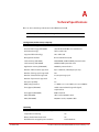
Related Documentation
• SFA OS CLUI Command Reference
• SFA10000 Quick Start Guide
• SFA10000 Release Notes
• StorageScaler 6000 User Guide
• StorageScaler 7000 User Guide
• StorageScaler 2460 User Guide
• 42U/45U 28" Wide Rack Installation and Service Guide
• SFA10000 White Paper
• SFA OS Service Manual
International Standards
The SFA10000 complies with the requirements of the following agencies and standards:
• CE
• UL
• CUL
• C-Tick
• FCC
Potential for Radio Frequency Interference
USA Federal Communications Commission (FCC)
This equipment has been tested and found to comply with the limits for a class A digital
device, pursuant to Part 15 of the FCC rules. These limits are designed to provide reasonable
protection against harmful interference when the equipment is operated in a commercial
environment. This equipment generates, uses and can radiate radio frequency energy and, if
not installed and used in accordance with the instruction manual, may cause harmful
interference to radio communications. Operation of this equipment in a residential area is
likely to cause harmful interference in which case the user will be required to correct the
interference at his own expense.
Properly shielded and grounded cables and connectors must be used in order to meet FCC
emission limits. The supplier is not responsible for any radio or television interference
caused by using other than recommended cables and connectors or by unauthorized
96-00259-001
DataDirect Networks SFA10000/10000E (V1.4.2) User Guide | xii
Preface
changes or modifications to this equipment. Unauthorized changes or modifications could
void the user’s authority to operate the equipment.
This device complies with Part 15 of the FCC Rules. Operation is subject to the following two
conditions: (1) this device may not cause harmful interference, and (2) this device must
accept any interference received, including interference that may cause undesired
operation.
European Regulations
This equipment complies with European Regulations EN 55022 Class A: Limits and Methods
of Measurement of Radio Disturbance Characteristics of Information Technology
Equipments and EN50082-1: Generic Immunity.
Canadian Regulations
ICES-003 Class A Notice - Avis NMB-003, Classe A
This Class A digital apparatus complies with Canadian ICES-003.
Cet appareil numérique de la classe A est conforme à la norme NMB-003 du Canada.
Safe Handling
• Remove drives to minimize weight.
• Do not lift the enclosure by yourself.
• Do not lift the SFA10000 by the handles at the front and on the power supply modules
on the back; they are not designed to support the weight of the enclosure.
Safety
NOTE :
!
Warning
If this equipment is used in a manner not specified by the manufacturer, the
protection provided by the equipment may be impaired.
The SFA10000 MUST be grounded before applying power. Unplug the
unit if you think that it has become damaged in any way and before you
move it.
CAUTION ! To maintain proper airflow through the system, operate the system with
the system top covers closed.
• Plug-in modules are part of the enclosure and must only be removed when a
replacement can be immediately installed. The system must not be run without all
modules in place.
• In order to comply with applicable safety, emission, and thermal requirements, the top
covers should remain closed while running.
• The SFA10000 system must only be operated from a power supply input voltage range
of 200 VAC to 240 VAC.
96-00259-001
DataDirect Networks SFA10000/10000E (V1.4.2) User Guide | xiii
Preface
• A faulty power supply or fan module must be replaced with a fully operational module
within 24 hours.
To minimize the risk of electric shock, disconnect the power from the
power supply, either by turning off the switch or by physically removing
the power cable, prior to removing the module from the enclosure.
• Do not remove a faulty power supply or fan module unless you have a replacement
module of the correct type ready for insertion.
• The power connection must always be disconnected prior to removal of the power
supply module from the SFA10000 or disk enclosures.
• A safe electrical earth connection must be provided to the power cord.
• Provide a suitable power source with electrical overload protection to meet the
requirements given in the technical specifications.
!
Warning
!
Warning
Do not remove covers from the power supply module. Danger of electric
shock inside. Return the module to your supplier for repair.
Operation of the SFA10000 with ANY modules missing will disrupt the
airflow and the components will not receive sufficient cooling. It is
ESSENTIAL that all apertures are filled before operating the unit.
Recycling of Waste Electrical and Electronic Equipment (WEEE)
At the end of the product’s life, all scrap/ waste electrical and electronic equipment should
be recycled in accordance with National regulations applicable to the handling of
hazardous/ toxic electrical and electronic waste materials.
NOTE :
Observe all applicable safety precautions, such as weight restrictions,
handling batteries and lasers etc, detailed in the preceding paragraphs
when dismantling and disposing of this equipment.
ESD Precautions
CAUTION ! When handling the SFA10000 plug-in modules and components, avoid
contact with backplane components and module connectors.
96-00259-001
DataDirect Networks SFA10000/10000E (V1.4.2) User Guide | xiv
Preface
Data Security
• Disk units are fragile. Handle them with care, and keep them away from strong magnetic
fields.
• ALL the supplied plug-in modules and blanking plates must be in place for the air to
flow correctly around the enclosure and also to complete the internal circuitry.
• If the SFA10000 or disk enclosure is used with modules or dummy disk modules missing
for more than a few minutes, the system can overheat, causing power failure and data
loss. Such use may also invalidate the warranty.
• If you remove a disk module, replace it immediately. If it is faulty, replace it with a disk
module of the same type and capacity.
• Ensure that all disk modules are removed from the enclosure before attempting to move
the rack installation.
• Do not abandon your backup routines. No system is completely foolproof.
96-00259-001
DataDirect Networks SFA10000/10000E (V1.4.2) User Guide | xv
Table of Contents
Preface
Chapter 1
Introduction
Related Documentation . . . . . . . . . . . . . . . . . . . . . . . . . . . . . . . . . . . . . . . . . . . . . . . . . . . . . . . . . . . . . . . . . . xii
International Standards . . . . . . . . . . . . . . . . . . . . . . . . . . . . . . . . . . . . . . . . . . . . . . . . . . . . . . . . . . . . . . . . . . . xii
Potential for Radio Frequency Interference . . . . . . . . . . . . . . . . . . . . . . . . . . . . . . . . . . . . . . . . . . . . . . xii
European Regulations . . . . . . . . . . . . . . . . . . . . . . . . . . . . . . . . . . . . . . . . . . . . . . . . . . . . . . . . . . . . . . . . . . . xiii
Canadian Regulations . . . . . . . . . . . . . . . . . . . . . . . . . . . . . . . . . . . . . . . . . . . . . . . . . . . . . . . . . . . . . . . . . . . . xiii
Safe Handling . . . . . . . . . . . . . . . . . . . . . . . . . . . . . . . . . . . . . . . . . . . . . . . . . . . . . . . . . . . . . . . . . . . . . . . . . . . . xiii
Safety . . . . . . . . . . . . . . . . . . . . . . . . . . . . . . . . . . . . . . . . . . . . . . . . . . . . . . . . . . . . . . . . . . . . . . . . . . . . . . . . . . . . . xiii
Recycling of Waste Electrical and Electronic Equipment (WEEE) . . . . . . . . . . . . . . . . . . . . . . . xiv
ESD Precautions . . . . . . . . . . . . . . . . . . . . . . . . . . . . . . . . . . . . . . . . . . . . . . . . . . . . . . . . . . . . . . . . . . . . . . . . . . xiv
Data Security . . . . . . . . . . . . . . . . . . . . . . . . . . . . . . . . . . . . . . . . . . . . . . . . . . . . . . . . . . . . . . . . . . . . . . . . . . . . . . xv
1.1 Introduction . . . . . . . . . . . . . . . . . . . . . . . . . . . . . . . . . . . . . . . . . . . . . . . . . . . . . . . . . . . . . . . . . . . . . . . . . . 2
1.1.1
DataDirect Networks’ Storage Fusion Architecture (SFA) . . . . . . . . . . . . . . . . . . . . 2
1.1.2
Product Variations. . . . . . . . . . . . . . . . . . . . . . . . . . . . . . . . . . . . . . . . . . . . . . . . . . . . . . . . . 2
1.1.3
Features of the SFA10000. . . . . . . . . . . . . . . . . . . . . . . . . . . . . . . . . . . . . . . . . . . . . . . . . . 3
1.2 The SFA10000 System Hardware . . . . . . . . . . . . . . . . . . . . . . . . . . . . . . . . . . . . . . . . . . . . . . . . . . . . 5
1.2.1
Status LED Indicators . . . . . . . . . . . . . . . . . . . . . . . . . . . . . . . . . . . . . . . . . . . . . . . . . . . . . . 7
1.2.2
Fan Module . . . . . . . . . . . . . . . . . . . . . . . . . . . . . . . . . . . . . . . . . . . . . . . . . . . . . . . . . . . . . . . 8
1.2.3
Power Supply Module . . . . . . . . . . . . . . . . . . . . . . . . . . . . . . . . . . . . . . . . . . . . . . . . . . . . . 8
1.2.4
Internal Disk Modules . . . . . . . . . . . . . . . . . . . . . . . . . . . . . . . . . . . . . . . . . . . . . . . . . . . . . 9
1.2.5
RAID Processor and Application Processor . . . . . . . . . . . . . . . . . . . . . . . . . . . . . . . . . 9
1.2.6
I/O Ports . . . . . . . . . . . . . . . . . . . . . . . . . . . . . . . . . . . . . . . . . . . . . . . . . . . . . . . . . . . . . . . . . 10
1.2.7
Uninterruptible Power Supplies (UPS) . . . . . . . . . . . . . . . . . . . . . . . . . . . . . . . . . . . . . 12
Chapter 2
Installation
2.1 Installation Overview . . . . . . . . . . . . . . . . . . . . . . . . . . . . . . . . . . . . . . . . . . . . . . . . . . . . . . . . . . . . . . . . 14
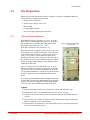
2.2 Site Preparation . . . . . . . . . . . . . . . . . . . . . . . . . . . . . . . . . . . . . . . . . . . . . . . . . . . . . . . . . . . . . . . . . . . . . 15
2.2.1
Delivery Route Verification. . . . . . . . . . . . . . . . . . . . . . . . . . . . . . . . . . . . . . . . . . . . . . . . 15
2.2.2
Rack Location, Air Flow, and Access . . . . . . . . . . . . . . . . . . . . . . . . . . . . . . . . . . . . . . . 16
2.2.3
Floor Loading . . . . . . . . . . . . . . . . . . . . . . . . . . . . . . . . . . . . . . . . . . . . . . . . . . . . . . . . . . . . 17
2.2.4
Cooling Supply Planning . . . . . . . . . . . . . . . . . . . . . . . . . . . . . . . . . . . . . . . . . . . . . . . . . 17
2.2.5
AC Power Supply Planning and Verification . . . . . . . . . . . . . . . . . . . . . . . . . . . . . . . 18
2.3 Unpacking the SFA10000 . . . . . . . . . . . . . . . . . . . . . . . . . . . . . . . . . . . . . . . . . . . . . . . . . . . . . . . . . . . 20
2.3.1
Packing List . . . . . . . . . . . . . . . . . . . . . . . . . . . . . . . . . . . . . . . . . . . . . . . . . . . . . . . . . . . . . . 20
2.4 Installing the Disk Modules . . . . . . . . . . . . . . . . . . . . . . . . . . . . . . . . . . . . . . . . . . . . . . . . . . . . . . . . . 21
2.5 Cable Connections . . . . . . . . . . . . . . . . . . . . . . . . . . . . . . . . . . . . . . . . . . . . . . . . . . . . . . . . . . . . . . . . . . 22
2.5.1
Couplet ICL Cabling . . . . . . . . . . . . . . . . . . . . . . . . . . . . . . . . . . . . . . . . . . . . . . . . . . . . . . 22
2.5.2
Disk Enclosure Cabling . . . . . . . . . . . . . . . . . . . . . . . . . . . . . . . . . . . . . . . . . . . . . . . . . . . 23
2.5.3
Host Connections . . . . . . . . . . . . . . . . . . . . . . . . . . . . . . . . . . . . . . . . . . . . . . . . . . . . . . . . 30
96-00259-001
DataDirect Networks SFA10000/10000E (V1.4.2) User Guide | xvi
Table of Contents
2.5.3.1
2.5.3.2
2.5.4
2.5.5
2.5.6
2.5.6.1
2.5.7
SFA10000 . . . . . . . . . . . . . . . . . . . . . . . . . . . . . . . . . . . . . . . . . . . . . . . . . . . . . . . . . . . . . . . . . . . . . 30
SFA10000E . . . . . . . . . . . . . . . . . . . . . . . . . . . . . . . . . . . . . . . . . . . . . . . . . . . . . . . . . . . . . . . . . . . . 30
Management Network Connection . . . . . . . . . . . . . . . . . . . . . . . . . . . . . . . . . . . . . . . 31
RS-232 Console Connection . . . . . . . . . . . . . . . . . . . . . . . . . . . . . . . . . . . . . . . . . . . . . . 31
UPS Connection . . . . . . . . . . . . . . . . . . . . . . . . . . . . . . . . . . . . . . . . . . . . . . . . . . . . . . . . . . 32
UPS Battery . . . . . . . . . . . . . . . . . . . . . . . . . . . . . . . . . . . . . . . . . . . . . . . . . . . . . . . . . . . . . . . . . . . 32
Power Connections. . . . . . . . . . . . . . . . . . . . . . . . . . . . . . . . . . . . . . . . . . . . . . . . . . . . . . . 33
2.6 Powering On the System . . . . . . . . . . . . . . . . . . . . . . . . . . . . . . . . . . . . . . . . . . . . . . . . . . . . . . . . . . . . 33
2.7 Configuring the SFA10000 . . . . . . . . . . . . . . . . . . . . . . . . . . . . . . . . . . . . . . . . . . . . . . . . . . . . . . . . . . 35
2.7.1
Planning Your Setup and Configuration . . . . . . . . . . . . . . . . . . . . . . . . . . . . . . . . . . . 35
2.7.2
Serial Interface Configuration . . . . . . . . . . . . . . . . . . . . . . . . . . . . . . . . . . . . . . . . . . . . . 36
2.7.3
Validate the Hardware . . . . . . . . . . . . . . . . . . . . . . . . . . . . . . . . . . . . . . . . . . . . . . . . . . . . 36
2.7.4
Clear System Configuration (not applicable to SFA10000E) . . . . . . . . . . . . . . . . 38
2.7.5
Set the System Name . . . . . . . . . . . . . . . . . . . . . . . . . . . . . . . . . . . . . . . . . . . . . . . . . . . . . 38
2.7.6
Set System Time & Date (NTP). . . . . . . . . . . . . . . . . . . . . . . . . . . . . . . . . . . . . . . . . . . . . 39
2.7.7
Configure Network Interface Settings . . . . . . . . . . . . . . . . . . . . . . . . . . . . . . . . . . . . . 39
2.7.8
Access Virtual Machines (SFA10000E Only) . . . . . . . . . . . . . . . . . . . . . . . . . . . . . . . . 40
2.7.9
Create Storage Pools . . . . . . . . . . . . . . . . . . . . . . . . . . . . . . . . . . . . . . . . . . . . . . . . . . . . . 41
2.7.10 Create Virtual Disks . . . . . . . . . . . . . . . . . . . . . . . . . . . . . . . . . . . . . . . . . . . . . . . . . . . . . . . 43
2.7.11 Create and Assign Spare Pools . . . . . . . . . . . . . . . . . . . . . . . . . . . . . . . . . . . . . . . . . . . . 45
2.7.12 Present Virtual Disk to External Host (not applicable to SFA10000E) . . . . . . . . 47
2.7.12.1
Special Considerations for MAC OS® . . . . . . . . . . . . . . . . . . . . . . . . . . . . . . . . . . . . . . . . . 50
2.7.12.2
Selective Presentation . . . . . . . . . . . . . . . . . . . . . . . . . . . . . . . . . . . . . . . . . . . . . . . . . . . . . . . . 50
2.7.13 Storage Pool Initialization . . . . . . . . . . . . . . . . . . . . . . . . . . . . . . . . . . . . . . . . . . . . . . . . 50
Chapter 3
Administration
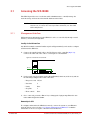
3.1 Accessing the SFA10000 . . . . . . . . . . . . . . . . . . . . . . . . . . . . . . . . . . . . . . . . . . . . . . . . . . . . . . . . . . . . 53
3.1.1
Management Interface . . . . . . . . . . . . . . . . . . . . . . . . . . . . . . . . . . . . . . . . . . . . . . . . . . . 53
3.1.2
User Logins . . . . . . . . . . . . . . . . . . . . . . . . . . . . . . . . . . . . . . . . . . . . . . . . . . . . . . . . . . . . . . 54
3.1.3
Available Commands . . . . . . . . . . . . . . . . . . . . . . . . . . . . . . . . . . . . . . . . . . . . . . . . . . . . . 54
3.1.3.1
Basic Key Operations . . . . . . . . . . . . . . . . . . . . . . . . . . . . . . . . . . . . . . . . . . . . . . . . . . . . . . . . . 55
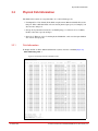
3.2 Physical Disk Information . . . . . . . . . . . . . . . . . . . . . . . . . . . . . . . . . . . . . . . . . . . . . . . . . . . . . . . . . . . 56
3.2.1
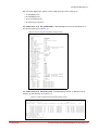
Disk Information . . . . . . . . . . . . . . . . . . . . . . . . . . . . . . . . . . . . . . . . . . . . . . . . . . . . . . . . . 56
3.2.2
Disk States . . . . . . . . . . . . . . . . . . . . . . . . . . . . . . . . . . . . . . . . . . . . . . . . . . . . . . . . . . . . . . . 58
3.3 Storage Pool Management . . . . . . . . . . . . . . . . . . . . . . . . . . . . . . . . . . . . . . . . . . . . . . . . . . . . . . . . . 59
3.3.1
Display Storage Pool Information . . . . . . . . . . . . . . . . . . . . . . . . . . . . . . . . . . . . . . . . . 59
3.3.2
Creating a Storage Pool. . . . . . . . . . . . . . . . . . . . . . . . . . . . . . . . . . . . . . . . . . . . . . . . . . . 61
3.3.3
SATAssure . . . . . . . . . . . . . . . . . . . . . . . . . . . . . . . . . . . . . . . . . . . . . . . . . . . . . . . . . . . . . . . 62
3.3.4
Background Verify Scan . . . . . . . . . . . . . . . . . . . . . . . . . . . . . . . . . . . . . . . . . . . . . . . . . . 63
3.3.5
Storage Pool Initialization . . . . . . . . . . . . . . . . . . . . . . . . . . . . . . . . . . . . . . . . . . . . . . . . 64
3.3.5.1
Initialization Job Failure . . . . . . . . . . . . . . . . . . . . . . . . . . . . . . . . . . . . . . . . . . . . . . . . . . . . . . 64
3.3.6
Naming a Storage Pool . . . . . . . . . . . . . . . . . . . . . . . . . . . . . . . . . . . . . . . . . . . . . . . . . . . 65
3.3.7
Deleting a Storage Pool. . . . . . . . . . . . . . . . . . . . . . . . . . . . . . . . . . . . . . . . . . . . . . . . . . . 65
96-00259-001
DataDirect Networks SFA10000/10000E (V1.4.2) User Guide | xvii
Table of Contents
3.4 Virtual Disk Management . . . . . . . . . . . . . . . . . . . . . . . . . . . . . . . . . . . . . . . . . . . . . . . . . . . . . . . . . . . 66
3.4.1
Display Virtual Disk Information. . . . . . . . . . . . . . . . . . . . . . . . . . . . . . . . . . . . . . . . . . . 66
3.4.2
Creating a Virtual Disk . . . . . . . . . . . . . . . . . . . . . . . . . . . . . . . . . . . . . . . . . . . . . . . . . . . . 67
3.4.3
Naming a Virtual Disk. . . . . . . . . . . . . . . . . . . . . . . . . . . . . . . . . . . . . . . . . . . . . . . . . . . . . 67
3.4.4
Deleting a Virtual Disk . . . . . . . . . . . . . . . . . . . . . . . . . . . . . . . . . . . . . . . . . . . . . . . . . . . . 68
3.4.5
Presentation to Hosts (not applicable to SFA10000E) . . . . . . . . . . . . . . . . . . . . . . 68
3.5 Spare Pool Management . . . . . . . . . . . . . . . . . . . . . . . . . . . . . . . . . . . . . . . . . . . . . . . . . . . . . . . . . . . . 69
3.5.1
Display Spare Pool Information . . . . . . . . . . . . . . . . . . . . . . . . . . . . . . . . . . . . . . . . . . . 69
3.5.2
Creating a Spare Pool. . . . . . . . . . . . . . . . . . . . . . . . . . . . . . . . . . . . . . . . . . . . . . . . . . . . . 70
3.5.3
Naming a Spare Pool . . . . . . . . . . . . . . . . . . . . . . . . . . . . . . . . . . . . . . . . . . . . . . . . . . . . . 70
3.5.4
Deleting a Spare Pool. . . . . . . . . . . . . . . . . . . . . . . . . . . . . . . . . . . . . . . . . . . . . . . . . . . . . 70
3.6 Presentations . . . . . . . . . . . . . . . . . . . . . . . . . . . . . . . . . . . . . . . . . . . . . . . . . . . . . . . . . . . . . . . . . . . . . . . . 71
3.6.1
Discovered Initiator Commands . . . . . . . . . . . . . . . . . . . . . . . . . . . . . . . . . . . . . . . . . . 72
3.6.2
Imported Initiator Commands . . . . . . . . . . . . . . . . . . . . . . . . . . . . . . . . . . . . . . . . . . . . 72
3.6.3
Host Commands . . . . . . . . . . . . . . . . . . . . . . . . . . . . . . . . . . . . . . . . . . . . . . . . . . . . . . . . . 72
3.6.4
Presentation Commands . . . . . . . . . . . . . . . . . . . . . . . . . . . . . . . . . . . . . . . . . . . . . . . . . 72
3.6.4.1
Persistent Reservation Support . . . . . . . . . . . . . . . . . . . . . . . . . . . . . . . . . . . . . . . . . . . . . . 73
3.6.5
Additional Configuration Considerations for Mac® Hosts . . . . . . . . . . . . . . . . . . . 73
3.6.6
Configure Presentations of Virtual Disks to Hosts . . . . . . . . . . . . . . . . . . . . . . . . . . 74
3.6.6.1
Create Host Object . . . . . . . . . . . . . . . . . . . . . . . . . . . . . . . . . . . . . . . . . . . . . . . . . . . . . . . . . . . 75
3.6.6.2
Identifying Host Connections via Ports . . . . . . . . . . . . . . . . . . . . . . . . . . . . . . . . . . . . . . 76
3.6.6.3
Import Discovered Initiators . . . . . . . . . . . . . . . . . . . . . . . . . . . . . . . . . . . . . . . . . . . . . . . . . 79
3.6.6.4
Present a Virtual Disk to a Host . . . . . . . . . . . . . . . . . . . . . . . . . . . . . . . . . . . . . . . . . . . . . . . 80
3.7 Visual Indications . . . . . . . . . . . . . . . . . . . . . . . . . . . . . . . . . . . . . . . . . . . . . . . . . . . . . . . . . . . . . . . . . . . . 82
3.7.1
Locate Dwell Time. . . . . . . . . . . . . . . . . . . . . . . . . . . . . . . . . . . . . . . . . . . . . . . . . . . . . . . . 82
3.8 Network Time Protocol Mode. . . . . . . . . . . . . . . . . . . . . . . . . . . . . . . . . . . . . . . . . . . . . . . . . . . . . . . 83
3.9 Disk Rebuild . . . . . . . . . . . . . . . . . . . . . . . . . . . . . . . . . . . . . . . . . . . . . . . . . . . . . . . . . . . . . . . . . . . . . . . . . 85
3.9.1
Full and Fractional Rebuilds. . . . . . . . . . . . . . . . . . . . . . . . . . . . . . . . . . . . . . . . . . . . . . . 85
3.9.2
Sparing Policy . . . . . . . . . . . . . . . . . . . . . . . . . . . . . . . . . . . . . . . . . . . . . . . . . . . . . . . . . . . . 85
3.9.3
Manual Disk Replace/Rebuild . . . . . . . . . . . . . . . . . . . . . . . . . . . . . . . . . . . . . . . . . . . . . 86
3.9.4
Manual Fail/Rebuild of a Disk . . . . . . . . . . . . . . . . . . . . . . . . . . . . . . . . . . . . . . . . . . . . . 86
3.10 Power Cycling the SFA10000 . . . . . . . . . . . . . . . . . . . . . . . . . . . . . . . . . . . . . . . . . . . . . . . . . . . . . . . 87
3.10.1 Reboot / Restart. . . . . . . . . . . . . . . . . . . . . . . . . . . . . . . . . . . . . . . . . . . . . . . . . . . . . . . . . . . 87
3.10.2 Shut Down / Power Cycle . . . . . . . . . . . . . . . . . . . . . . . . . . . . . . . . . . . . . . . . . . . . . . . . . 87
3.10.2.1
Power Cycling One Controller . . . . . . . . . . . . . . . . . . . . . . . . . . . . . . . . . . . . . . . . . . . . . . . . 87
3.10.2.2
Power Cycling Both Controllers . . . . . . . . . . . . . . . . . . . . . . . . . . . . . . . . . . . . . . . . . . . . . . 87
3.11 Performance Management . . . . . . . . . . . . . . . . . . . . . . . . . . . . . . . . . . . . . . . . . . . . . . . . . . . . . . . . . 88
3.11.1 Cache Coherency. . . . . . . . . . . . . . . . . . . . . . . . . . . . . . . . . . . . . . . . . . . . . . . . . . . . . . . . . 88
3.11.1.1
Cache Protection . . . . . . . . . . . . . . . . . . . . . . . . . . . . . . . . . . . . . . . . . . . . . . . . . . . . . . . . . . . . . 88
3.11.2 Single Controller Write Back Cache Policy . . . . . . . . . . . . . . . . . . . . . . . . . . . . . . . . . 88
3.11.3 Right Side I/O . . . . . . . . . . . . . . . . . . . . . . . . . . . . . . . . . . . . . . . . . . . . . . . . . . . . . . . . . . . . 89
3.11.4 Background Job Priority . . . . . . . . . . . . . . . . . . . . . . . . . . . . . . . . . . . . . . . . . . . . . . . . . . 90
96-00259-001
DataDirect Networks SFA10000/10000E (V1.4.2) User Guide | xviii
Table of Contents
3.11.4.1
Pause/Resume a Job . . . . . . . . . . . . . . . . . . . . . . . . . . . . . . . . . . . . . . . . . . . . . . . . . . . . . . . . . . 91
3.11.5 Rebuild Policy Priority . . . . . . . . . . . . . . . . . . . . . . . . . . . . . . . . . . . . . . . . . . . . . . . . . . . . 91
3.12 The System Logs . . . . . . . . . . . . . . . . . . . . . . . . . . . . . . . . . . . . . . . . . . . . . . . . . . . . . . . . . . . . . . . . . . . . 93
3.12.1 Displaying Event Logs . . . . . . . . . . . . . . . . . . . . . . . . . . . . . . . . . . . . . . . . . . . . . . . . . . . . 93
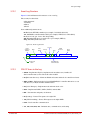
3.12.2 Event Log Structure . . . . . . . . . . . . . . . . . . . . . . . . . . . . . . . . . . . . . . . . . . . . . . . . . . . . . . 94
3.12.3 SFA OS Terms in the Log. . . . . . . . . . . . . . . . . . . . . . . . . . . . . . . . . . . . . . . . . . . . . . . . . . 94
3.12.4 Marking Event Logs . . . . . . . . . . . . . . . . . . . . . . . . . . . . . . . . . . . . . . . . . . . . . . . . . . . . . . 95
3.12.5 Synchronize Log Disks . . . . . . . . . . . . . . . . . . . . . . . . . . . . . . . . . . . . . . . . . . . . . . . . . . . . 95
3.13 Remote Management of SFA10000. . . . . . . . . . . . . . . . . . . . . . . . . . . . . . . . . . . . . . . . . . . . . . . . . 96
3.13.1 Network Connection . . . . . . . . . . . . . . . . . . . . . . . . . . . . . . . . . . . . . . . . . . . . . . . . . . . . . 96
3.13.2 Display Network Interface Attributes . . . . . . . . . . . . . . . . . . . . . . . . . . . . . . . . . . . . . . 96
3.13.3 Change Network Interface Settings . . . . . . . . . . . . . . . . . . . . . . . . . . . . . . . . . . . . . . . 96
3.13.4 Logins . . . . . . . . . . . . . . . . . . . . . . . . . . . . . . . . . . . . . . . . . . . . . . . . . . . . . . . . . . . . . . . . . . . 97
3.13.5 Email and SNMP Notification Setup . . . . . . . . . . . . . . . . . . . . . . . . . . . . . . . . . . . . . . . 97
3.13.5.1
Email Setup . . . . . . . . . . . . . . . . . . . . . . . . . . . . . . . . . . . . . . . . . . . . . . . . . . . . . . . . . . . . . . . . . . . 97
3.13.5.2
SNMP Setup . . . . . . . . . . . . . . . . . . . . . . . . . . . . . . . . . . . . . . . . . . . . . . . . . . . . . . . . . . . . . . . . . . . 98
3.13.5.3
Inquiry Items and Events . . . . . . . . . . . . . . . . . . . . . . . . . . . . . . . . . . . . . . . . . . . . . . . . . . . . . 98
Chapter 4
GUI Management
Agent
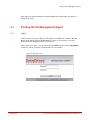
4.1 Starting the GUI Management Agent. . . . . . . . . . . . . . . . . . . . . . . . . . . . . . . . . . . . . . . . . . . . . .102
4.1.1
Login . . . . . . . . . . . . . . . . . . . . . . . . . . . . . . . . . . . . . . . . . . . . . . . . . . . . . . . . . . . . . . . . . . . 102
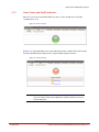
4.1.2
Home Screen and Health Indicators . . . . . . . . . . . . . . . . . . . . . . . . . . . . . . . . . . . . . . 103
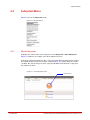
4.2 Subsystem Menu . . . . . . . . . . . . . . . . . . . . . . . . . . . . . . . . . . . . . . . . . . . . . . . . . . . . . . . . . . . . . . . . . . .104
4.2.1
Show Subsystem . . . . . . . . . . . . . . . . . . . . . . . . . . . . . . . . . . . . . . . . . . . . . . . . . . . . . . . . 104
4.2.2
Set Subsystem Attributes . . . . . . . . . . . . . . . . . . . . . . . . . . . . . . . . . . . . . . . . . . . . . . . . 105
4.2.2.1
NTP Settings . . . . . . . . . . . . . . . . . . . . . . . . . . . . . . . . . . . . . . . . . . . . . . . . . . . . . . . . . . . . . . . . .105
4.2.2.2
Locate Time . . . . . . . . . . . . . . . . . . . . . . . . . . . . . . . . . . . . . . . . . . . . . . . . . . . . . . . . . . . . . . . . . .105
4.2.3
Show Background Jobs . . . . . . . . . . . . . . . . . . . . . . . . . . . . . . . . . . . . . . . . . . . . . . . . . . 106
4.2.4
Set Background Jobs Attributes. . . . . . . . . . . . . . . . . . . . . . . . . . . . . . . . . . . . . . . . . . 106
4.2.5
Email and Critical Event Notification Setup . . . . . . . . . . . . . . . . . . . . . . . . . . . . . . . 106
4.3 Controllers Menu . . . . . . . . . . . . . . . . . . . . . . . . . . . . . . . . . . . . . . . . . . . . . . . . . . . . . . . . . . . . . . . . . . .108
4.3.1
Show Controllers . . . . . . . . . . . . . . . . . . . . . . . . . . . . . . . . . . . . . . . . . . . . . . . . . . . . . . . . 108
4.3.2
Set Controller Attributes . . . . . . . . . . . . . . . . . . . . . . . . . . . . . . . . . . . . . . . . . . . . . . . . . 108
4.3.3
Update Controller Firmware . . . . . . . . . . . . . . . . . . . . . . . . . . . . . . . . . . . . . . . . . . . . . 109
4.3.4
View System Logs . . . . . . . . . . . . . . . . . . . . . . . . . . . . . . . . . . . . . . . . . . . . . . . . . . . . . . . 109
4.4 Physical Disks Menu . . . . . . . . . . . . . . . . . . . . . . . . . . . . . . . . . . . . . . . . . . . . . . . . . . . . . . . . . . . . . . . .110
4.4.1
Show List of Physical Disks . . . . . . . . . . . . . . . . . . . . . . . . . . . . . . . . . . . . . . . . . . . . . . . 110
4.4.2
Locate Disks. . . . . . . . . . . . . . . . . . . . . . . . . . . . . . . . . . . . . . . . . . . . . . . . . . . . . . . . . . . . . 111
4.4.3
Remove Disk from Spare Pool. . . . . . . . . . . . . . . . . . . . . . . . . . . . . . . . . . . . . . . . . . . . 111
4.4.4
Assign Disks to Pool . . . . . . . . . . . . . . . . . . . . . . . . . . . . . . . . . . . . . . . . . . . . . . . . . . . . . 111
4.5 Unassigned Pool . . . . . . . . . . . . . . . . . . . . . . . . . . . . . . . . . . . . . . . . . . . . . . . . . . . . . . . . . . . . . . . . . . .112
4.5.1
Show Unassigned Pool . . . . . . . . . . . . . . . . . . . . . . . . . . . . . . . . . . . . . . . . . . . . . . . . . . 112
4.5.2
Locate Unassigned Pool . . . . . . . . . . . . . . . . . . . . . . . . . . . . . . . . . . . . . . . . . . . . . . . . . 113
96-00259-001
DataDirect Networks SFA10000/10000E (V1.4.2) User Guide | xix
Table of Contents
4.6 Storage Pools . . . . . . . . . . . . . . . . . . . . . . . . . . . . . . . . . . . . . . . . . . . . . . . . . . . . . . . . . . . . . . . . . . . . . . .114
4.6.1
Show List of Storage Pools . . . . . . . . . . . . . . . . . . . . . . . . . . . . . . . . . . . . . . . . . . . . . . . 114
4.6.2
Create a Storage Pool. . . . . . . . . . . . . . . . . . . . . . . . . . . . . . . . . . . . . . . . . . . . . . . . . . . . 115
4.6.3
Configure Storage Pool Attributes . . . . . . . . . . . . . . . . . . . . . . . . . . . . . . . . . . . . . . . 116
4.6.4
Locate Storage Pools . . . . . . . . . . . . . . . . . . . . . . . . . . . . . . . . . . . . . . . . . . . . . . . . . . . . 117
4.6.5
Delete a Storage Pool. . . . . . . . . . . . . . . . . . . . . . . . . . . . . . . . . . . . . . . . . . . . . . . . . . . . 117
4.7 Virtual Disks Menu . . . . . . . . . . . . . . . . . . . . . . . . . . . . . . . . . . . . . . . . . . . . . . . . . . . . . . . . . . . . . . . . .118
4.7.1
Show List of Virtual Disks . . . . . . . . . . . . . . . . . . . . . . . . . . . . . . . . . . . . . . . . . . . . . . . . 118
4.7.2
Create a Virtual Disk . . . . . . . . . . . . . . . . . . . . . . . . . . . . . . . . . . . . . . . . . . . . . . . . . . . . . 119
4.7.3
Configure Virtual Disk Attributes . . . . . . . . . . . . . . . . . . . . . . . . . . . . . . . . . . . . . . . . . 119
4.7.4
Delete a Virtual Disk . . . . . . . . . . . . . . . . . . . . . . . . . . . . . . . . . . . . . . . . . . . . . . . . . . . . . 120
4.8 Spare Pools . . . . . . . . . . . . . . . . . . . . . . . . . . . . . . . . . . . . . . . . . . . . . . . . . . . . . . . . . . . . . . . . . . . . . . . . .121
4.8.1
Show Spare Pools . . . . . . . . . . . . . . . . . . . . . . . . . . . . . . . . . . . . . . . . . . . . . . . . . . . . . . . 121
4.8.2
Locate a Spare Pool . . . . . . . . . . . . . . . . . . . . . . . . . . . . . . . . . . . . . . . . . . . . . . . . . . . . . 122
4.8.3
Create a Spare Pool. . . . . . . . . . . . . . . . . . . . . . . . . . . . . . . . . . . . . . . . . . . . . . . . . . . . . . 122
4.8.4
Assign Spare Pool to Storage Pool . . . . . . . . . . . . . . . . . . . . . . . . . . . . . . . . . . . . . . . 123
4.8.5
Set Spare Pool Attributes . . . . . . . . . . . . . . . . . . . . . . . . . . . . . . . . . . . . . . . . . . . . . . . . 124
4.8.6
Delete a Spare Pool. . . . . . . . . . . . . . . . . . . . . . . . . . . . . . . . . . . . . . . . . . . . . . . . . . . . . . 124
4.8.7
Delete a Disk from Spare Pool. . . . . . . . . . . . . . . . . . . . . . . . . . . . . . . . . . . . . . . . . . . . 124
4.9 Presentations . . . . . . . . . . . . . . . . . . . . . . . . . . . . . . . . . . . . . . . . . . . . . . . . . . . . . . . . . . . . . . . . . . . . . . .125
4.9.1
Presentation Menu . . . . . . . . . . . . . . . . . . . . . . . . . . . . . . . . . . . . . . . . . . . . . . . . . . . . . . 126
4.9.2
Show Presentations . . . . . . . . . . . . . . . . . . . . . . . . . . . . . . . . . . . . . . . . . . . . . . . . . . . . . 126
4.9.3
Set Up a Presentation. . . . . . . . . . . . . . . . . . . . . . . . . . . . . . . . . . . . . . . . . . . . . . . . . . . . 126
4.9.3.1
Create a Host. . . . . . . . . . . . . . . . . . . . . . . . . . . . . . . . . . . . . . . . . . . . . . . . . . . . . . . . . . . . . . . . .126
4.9.3.2
Map Host to Discovered Initiators . . . . . . . . . . . . . . . . . . . . . . . . . . . . . . . . . . . . . . . . . .127
4.9.3.3
Present Virtual Disks to Hosts . . . . . . . . . . . . . . . . . . . . . . . . . . . . . . . . . . . . . . . . . . . . . . .127
4.10 Enclosures Menu . . . . . . . . . . . . . . . . . . . . . . . . . . . . . . . . . . . . . . . . . . . . . . . . . . . . . . . . . . . . . . . . . . .128
4.10.1 Show Enclosures . . . . . . . . . . . . . . . . . . . . . . . . . . . . . . . . . . . . . . . . . . . . . . . . . . . . . . . . 128
4.10.2 Show UPS . . . . . . . . . . . . . . . . . . . . . . . . . . . . . . . . . . . . . . . . . . . . . . . . . . . . . . . . . . . . . . . 128
4.10.3 Update Enclosure Firmware . . . . . . . . . . . . . . . . . . . . . . . . . . . . . . . . . . . . . . . . . . . . . 129
Chapter 5
Support
5.1 “RAID[0]$” Prompt is not shown correctly . . . . . . . . . . . . . . . . . . . . . . . . . . . . . . . . . . . . . . . . .131
5.2 Event Log . . . . . . . . . . . . . . . . . . . . . . . . . . . . . . . . . . . . . . . . . . . . . . . . . . . . . . . . . . . . . . . . . . . . . . . . . . .131
5.3 Manual Intervention Required (MIR) States . . . . . . . . . . . . . . . . . . . . . . . . . . . . . . . . . . . . . . .132
5.4 Firmware Update . . . . . . . . . . . . . . . . . . . . . . . . . . . . . . . . . . . . . . . . . . . . . . . . . . . . . . . . . . . . . . . . . . .134
5.4.1
Displaying Current Firmware Version. . . . . . . . . . . . . . . . . . . . . . . . . . . . . . . . . . . . . 135
5.4.2
Controller Firmware Update Procedure . . . . . . . . . . . . . . . . . . . . . . . . . . . . . . . . . . 135
5.4.2.1
Linux Environment-Firmware Update from the Network . . . . . . . . . . . . . . . . . .136
5.4.2.2
Windows Environment-Firmware Update from the Network . . . . . . . . . . . . . .137
5.4.3
Disk Enclosure Firmware Update Procedure . . . . . . . . . . . . . . . . . . . . . . . . . . . . . . 139
5.4.3.1
Enclosure File Definitions . . . . . . . . . . . . . . . . . . . . . . . . . . . . . . . . . . . . . . . . . . . . . . . . . . .139
96-00259-001
DataDirect Networks SFA10000/10000E (V1.4.2) User Guide | xx
Table of Contents
5.4.3.2
Linux Environment-Firmware Upload . . . . . . . . . . . . . . . . . . . . . . . . . . . . . . . . . . . . . .140
5.4.3.3
Windows Environment-Firmware Upload . . . . . . . . . . . . . . . . . . . . . . . . . . . . . . . . . .140
5.4.3.4
Disk Shelf Upgrade . . . . . . . . . . . . . . . . . . . . . . . . . . . . . . . . . . . . . . . . . . . . . . . . . . . . . . . . . .140
5.4.4
Physical Disk Firmware Update Procedure. . . . . . . . . . . . . . . . . . . . . . . . . . . . . . . . 143
5.4.4.1
Linux Environment-Firmware Upload . . . . . . . . . . . . . . . . . . . . . . . . . . . . . . . . . . . . . .143
5.4.4.2
Windows Environment-Firmware Upload . . . . . . . . . . . . . . . . . . . . . . . . . . . . . . . . . .144
5.4.4.3
Physical Disk Upgrade . . . . . . . . . . . . . . . . . . . . . . . . . . . . . . . . . . . . . . . . . . . . . . . . . . . . . . .144
5.5 UPS Maintenance. . . . . . . . . . . . . . . . . . . . . . . . . . . . . . . . . . . . . . . . . . . . . . . . . . . . . . . . . . . . . . . . . . .146
5.5.1
UPS and Battery Pack Care . . . . . . . . . . . . . . . . . . . . . . . . . . . . . . . . . . . . . . . . . . . . . . . 146
5.5.2
Checking the UPS Status. . . . . . . . . . . . . . . . . . . . . . . . . . . . . . . . . . . . . . . . . . . . . . . . . 146
5.5.3
End of Life Warning . . . . . . . . . . . . . . . . . . . . . . . . . . . . . . . . . . . . . . . . . . . . . . . . . . . . . 149
5.5.4
Replacing the Battery Pack. . . . . . . . . . . . . . . . . . . . . . . . . . . . . . . . . . . . . . . . . . . . . . . 150
5.5.4.1
Testing Batteries . . . . . . . . . . . . . . . . . . . . . . . . . . . . . . . . . . . . . . . . . . . . . . . . . . . . . . . . . . . . .152
5.5.5
Replacing the UPS Unit . . . . . . . . . . . . . . . . . . . . . . . . . . . . . . . . . . . . . . . . . . . . . . . . . . 152
5.6 Recovery from Disk Failure . . . . . . . . . . . . . . . . . . . . . . . . . . . . . . . . . . . . . . . . . . . . . . . . . . . . . . . . .155
5.6.1
Automatic Rebuild . . . . . . . . . . . . . . . . . . . . . . . . . . . . . . . . . . . . . . . . . . . . . . . . . . . . . . 155
5.6.2
Spare Disk Replacement . . . . . . . . . . . . . . . . . . . . . . . . . . . . . . . . . . . . . . . . . . . . . . . . . 156
5.6.3
When a Spare is not available . . . . . . . . . . . . . . . . . . . . . . . . . . . . . . . . . . . . . . . . . . . . 156
5.6.4
Manual Rebuild . . . . . . . . . . . . . . . . . . . . . . . . . . . . . . . . . . . . . . . . . . . . . . . . . . . . . . . . . 156
5.6.5
Power Cycling SATA Disk Drives. . . . . . . . . . . . . . . . . . . . . . . . . . . . . . . . . . . . . . . . . . 157
5.7 Controller Component Failures . . . . . . . . . . . . . . . . . . . . . . . . . . . . . . . . . . . . . . . . . . . . . . . . . . . .158
5.7.1
Replacing a Power Supply Module . . . . . . . . . . . . . . . . . . . . . . . . . . . . . . . . . . . . . . . 159
5.7.2
Replacing a Fan Module . . . . . . . . . . . . . . . . . . . . . . . . . . . . . . . . . . . . . . . . . . . . . . . . . 160
5.7.3
Replacing an Internal Disk Module . . . . . . . . . . . . . . . . . . . . . . . . . . . . . . . . . . . . . . . 161
5.7.4
Replacing a Controller . . . . . . . . . . . . . . . . . . . . . . . . . . . . . . . . . . . . . . . . . . . . . . . . . . . 162
5.8 Disk Enclosure Component Failures . . . . . . . . . . . . . . . . . . . . . . . . . . . . . . . . . . . . . . . . . . . . . . .165
5.8.1
I/O Module Replacement . . . . . . . . . . . . . . . . . . . . . . . . . . . . . . . . . . . . . . . . . . . . . . . . 165
5.8.2
DEM Replacement on SS6000. . . . . . . . . . . . . . . . . . . . . . . . . . . . . . . . . . . . . . . . . . . . 166
5.8.3
SAS Cable Replacement . . . . . . . . . . . . . . . . . . . . . . . . . . . . . . . . . . . . . . . . . . . . . . . . . 167
5.8.4
SS7000 Enclosure Replacement Procedure . . . . . . . . . . . . . . . . . . . . . . . . . . . . . . . 168
Appendices
Appendix A. Technical Specifications . . . . . . . . . . . . . . . . . . . . . . . . . . . . . . . . . . . . . . . . . . . . . . . . . .170
Appendix B. FRU Part Numbers . . . . . . . . . . . . . . . . . . . . . . . . . . . . . . . . . . . . . . . . . . . . . . . . . . . . . . . .173
Appendix C. Disk Module Installation . . . . . . . . . . . . . . . . . . . . . . . . . . . . . . . . . . . . . . . . . . . . . . . . . .175
C.1
SS6000 Disk Module Installation Procedure . . . . . . . . . . . . . . . . . . . . . . . . . . . . . . 175
C.2
SS7000 Disk Module Installation Procedure . . . . . . . . . . . . . . . . . . . . . . . . . . . . . . 176
C.3
SS2460 Disk Module Installation Procedure . . . . . . . . . . . . . . . . . . . . . . . . . . . . . . 177
Appendix D. SS6000 Disk Maps for SFA10000E . . . . . . . . . . . . . . . . . . . . . . . . . . . . . . . . . . . . . . . .178
Appendix E. Zoning Configuration Procedure. . . . . . . . . . . . . . . . . . . . . . . . . . . . . . . . . . . . . . . . .179
E.1
SS6000 Enclosures. . . . . . . . . . . . . . . . . . . . . . . . . . . . . . . . . . . . . . . . . . . . . . . . . . . . . . . 179
E.2
SS7000 Enclosures. . . . . . . . . . . . . . . . . . . . . . . . . . . . . . . . . . . . . . . . . . . . . . . . . . . . . . . 180
96-00259-001
DataDirect Networks SFA10000/10000E (V1.4.2) User Guide | xxi
Table of Contents
Appendix F. Rack Installation Procedure . . . . . . . . . . . . . . . . . . . . . . . . . . . . . . . . . . . . . . . . . . . . . .181
F.1
Rackmounting the Controller . . . . . . . . . . . . . . . . . . . . . . . . . . . . . . . . . . . . . . . . . . . . 181
F.2
Rackmounting the UPS Unit . . . . . . . . . . . . . . . . . . . . . . . . . . . . . . . . . . . . . . . . . . . . . 187
Appendix G. Temperature Sensor Locations . . . . . . . . . . . . . . . . . . . . . . . . . . . . . . . . . . . . . . . . . . .189
G.1
SFA10000 Controller . . . . . . . . . . . . . . . . . . . . . . . . . . . . . . . . . . . . . . . . . . . . . . . . . . . . 189
G.2
SS6000 Disk Enclosure . . . . . . . . . . . . . . . . . . . . . . . . . . . . . . . . . . . . . . . . . . . . . . . . . . . 191
G.3
SS7000 Disk Enclosure . . . . . . . . . . . . . . . . . . . . . . . . . . . . . . . . . . . . . . . . . . . . . . . . . . . 192
G.4
SS2460 Disk Enclosure . . . . . . . . . . . . . . . . . . . . . . . . . . . . . . . . . . . . . . . . . . . . . . . . . . . 193
Appendix H. Terminology . . . . . . . . . . . . . . . . . . . . . . . . . . . . . . . . . . . . . . . . . . . . . . . . . . . . . . . . . . . . . .194
Index. . . . . . . . . . . . . . . . . . . . . . . . . . . . . . . . . . . . . . . . . . . . . . . . . . . . . . . . . . . . . . . . . . . . . . . . . . . . . . . . . . . . . .196
Contacting Technical Support & Shipping Instructions . . . . . . . . . . . . . . . . . . . . . . . . . . . . . . . .199
96-00259-001
DataDirect Networks SFA10000/10000E (V1.4.2) User Guide | xxii
Chapter 1
Introduction
96-00259-001
DataDirect Networks SFA10000/10000E (V1.4.2) User Guide | 1
Introduction
1.1
Introduction
Welcome to the DataDirect Networks SFA10000 User Guide.
1.1.1
DataDirect Networks’ Storage Fusion Architecture (SFA)
DDN’s Storage Fusion Architecture provides the foundation for balanced, high-performance
storage system. Using highly parallelized storage processing technology, SFA delivers both
unprecedented IOPS and massive throughput. Combined with Enterprise-level data
protection and leading scalability, density and energy efficiency, SFA is the storage
technology of choice for the most extreme storage infrastructure projects.
The SFA10000 employs RAID, data integrity and data management software written from the
ground up to take advantage of multi-core processors and modern bus architectures. Its
highly threaded architecture allows performance to linearly scale with advances in
underlying hardware. This same architecture allows the SFA10000 to perform in the extreme
range of both throughput and IOPS. Designed to house the most scalable unstructured file
data, the system supports up to 1200 disks of raw storage while enabling a combination of
SAS, SATA or SSD disks.
1.1.2
Product Variations
Various configurations (Figure 1) are available with the SFA10000 to enable full system
performance, capacity, and the highest levels of disk enclosure fault tolerance.
• Five 60-bay disk enclosures with up to 300 disk modules at 28U in one rack
• Ten 60-bay disk enclosures with up to 600 disk modules at 48U in two racks
• Twenty 60-bay disk enclosures with up to 1200 disk modules at 88U in two racks
• Five 24-bay disk enclosures with up to 120 disk modules at 18U in one rack
Figure 1. SFA10000 Possible Configurations
96-00259-001
9 Component System
14 Component System
24 Component System
(
(
(
2 Controllers & 2 UPS
5 Disk Enclosures
)
2 Controllers & 2 UPS
10 Disk Enclosures
)
2 Controllers & 2 UPS
20 Disk Enclosures
)
DataDirect Networks SFA10000/10000E (V1.4.2) User Guide | 2
Introduction
1.1.3
Features of the SFA10000
The SFA10000 incorporates the following features:
• 8 GB/s full-duplex cache link
• Internal SAS Switching (480 Gb/s Internal SAS Storage Network)
• Up to 1200 SAS, SATA, or SSD disks with full redundant paths
• InfiniBand™ (IB) or Fibre Channel (FC) Connectivity on SFA10000
For SFA10000 IB option, the two Controllers provide up to eight (8) QDR InfiniBand
host port connections.
For SFA10000 FC option, the two Controllers provide up to sixteen (16) individual
8 Gb/s Fibre Channel host port connections, including simultaneous access to the same
data through multiple ports. Each FC host port supports point-to-point and switched
fabric operation.
• InfiniBand or 10 Gigabit Ethernet Connectivity on SFA10000E
The SFA10000E provides up to 16 individual IB or 10GbE ports for host access to the
Virtual Machines. Each port can be configured to run as either InfiniBand QDR or 10
Gigabit Ethernet. 10 Gigabit Ethernet connectivity requires special cabling that can be
purchased separately from DDN. See your sales contact for more details.
• Active/Active Operation with Cache Coherency and Failover
SFA implements an active/active host presentation model with routing-based data
access and full cache coherency.
• Data Protection
The SFA RAID stack provides protection against single physical disk failures with
RAID 1 or RAID 5 data protection as well as double physical disk failures through the
use of high-speed RAID 6 protection.
• Configurable RAID Group Sizes
(5 or 9 disks / RAID 5 group, 6 or 10 disks / RAID 6 group, 2 disks / RAID 1 group)
This feature allows you to configure the system with the desired RAID and redundancy
levels based on data requirements. Each RAID group is configured independently and
any valid combination for the number of disks in the array is supported.
• SAS / SATA / SSD storage pool
Intermixing high-performance SSD and SAS disks with high-capacity SATA disks
provides the flexibility to migrate disk technology along with varying application needs.
The SFA10000’s enclosure-level disk intermixing and exceptional per-disk performance
reduces the number of disks needed to meet growing performance and capacity
demands—lowering both acquisition and operation costs.
• SATAssure™ Data Protection
SATAssure technology (Silent Data Corruption Detection and Avoidance) is designed by
DDN to improve the reliability of enterprise SATA disks and make sure that data
integrity is always mentioned for all I/O operations.
• ReACT™ Intelligent Cache Management
Analyzes and optimizes I/O traffic to write large file sequential data directly to disk and
preserve valuable cache for random I/O transactions.
• Battery-Backed Write Back Cache
SFA OS provides a write back cache feature that is used to improve I/O performance.
Write back cache data that has not been written to disk is preserved by maintaining
96-00259-001
DataDirect Networks SFA10000/10000E (V1.4.2) User Guide | 3
Introduction
power to the cache memory in the event of an AC mains failure long enough to copy the
contents of the cache to stable storage. In addition, SFA OS is designed to tolerate a
simultaneous AC mains failure.
• Mirrored Write Back Cache
Currently, SFA OS provides the ability to mirror all write back cache data such that the
failure of a single controller will not result in data loss. A storage administrator can
optionally turn off write back cache mirroring for a RAID set (for higher performance);
however, data protection is reduced for logical units within that RAID set.
• Mirrored Transaction Journal
RAID write holes are prevented by executing stripe updates as ACID (Atomicity,
Consistency, Isolation, Durability) transactions. If the transactions are interrupted by a
power failure, they can be recovered from the transaction journal implemented within
the write back cache when power is restored. This journal is mirrored so that should a
simultaneous power failure and controller hardware failure occurs, the surviving
controller can recover the transactions.
• Storage Metadata Mirrored n-Ways
SFA OS stores a copy of storage system metadata on 18 physical disks to minimize the
likelihood that its metadata is lost or corrupted.
• Partial Rebuild
This feature reduces rebuild times by updating only the data that has changed while the
disk was down. The SFA OS tracks the changes made to a RAID set when a member
physical disk becomes unavailable. If that member becomes available again, within a
user-definable timeout, only the stripes that were modified while the member was
missing are rebuilt. This minimizes the mean-time-to-repair for the RAID set and thus
limits any performance impact of a disk repair.
• Hot-Swappable and Redundant Components
Adhering to enterprise RAS standards, most hardware components (such as physical
disks, power supply modules, and fan module) are redundant and hot-swappable.
• Hot Spares
The SFA OS provides pools of spare physical disks that can be automatically used to
replace failed physical disks. By replacing a failed RAID set member automatically, the
mean-time-to-repair for the RAID set is minimized resulting in improved data reliability.
• Management Options via RS-232 and Ethernet (SSH)
A RS-232 port and Ethernet ports are included to provide local and remote management
capabilities.
96-00259-001
DataDirect Networks SFA10000/10000E (V1.4.2) User Guide | 4
The SFA10000 System Hardware
1.2
The SFA10000 System Hardware
This section describes the hardware components of the SFA10000 controller. Refer to DDN
SS6000 User Guide, DDN SS7000 User Guide, and DDN SS2460 User Guide for
hardware descriptions on the SS6000, SS7000, and SS2460 disk enclosures.
The SFA10000 controller is a three-unit (3U), rack-mountable enclosure (Figure 2).
Figure 2. SFA10000 Controller Chassis
At the front, there are four fan modules, three internal disk modules, control buttons and
status LED indicators (Figure 3).
Figure 3. SFA10000 Controller Front View without Bezel
Internal Disk
Disk A
Fan Modules (x4)
96-00259-001
Internal Disk
Disk B
Internal Disk
Disk C
Control Buttons/LEDs
DataDirect Networks SFA10000/10000E (V1.4.2) User Guide | 5
The SFA10000 System Hardware
At the back, there are two power supply modules and various I/O connectors. Figure 4 and
Figure 5 illustrate the rear views of the SFA10000 and SFA10000E controllers respectively.
Figure 4. SFA10000 Controller Rear View
Power Supply
Module 1
D
Power Supply
Module 2
LAN2
LAN4
LAN6
LAN1
LAN3
LAN5
Ethernet
Ports
Host Ports
(Client Channels)
IB Inter-Controller Link
IB Inter-Controller Link
USB
Ports
C
B
A
Host Ports
(Client Channels)
A
B
C
RS-232
Port
D
Disk Channels
Figure 5. SFA10000E Controller Rear View
Power Supply
Module 1
Host Ports
Disk Channels
D
Power Supply
Module 2
96-00259-001
LAN2
LAN4
LAN6
LAN1
LAN3
LAN5
Ethernet
Ports
USB
Ports
C
B
A
IB Inter-Controller Link
A
RS-232
Port
B
C
D
Host Ports
DataDirect Networks SFA10000/10000E (V1.4.2) User Guide | 6
The SFA10000 System Hardware
1.2.1
Status LED Indicators
Figure 6 below illustrates the positions of all the control buttons and LED indicators on the
front panel. The LEDs are defined in Table 1. The USB port can be used for downloading new
firmware and BIOS to the controller.
Figure 6. Controller Front Panel Control Buttons and Status LED Indicators
Management Network Activity LED
Ethernet
ICL Activity
Enclosure
Fault LED
Ethernet ICL Activity
USB Port
Locate/Identify Indicator
Power Indicator
On/Off Button
Internal HDD Activity
(DO NOT USE)
Ethernet ICL Activity
Ethernet ICL Activity
NOTE :
Do NOT use the Power button under normal operation since doing so may
cause data loss. If you need to power down the controller, issue the
SHUTDOWN command via CLUI or GUI first, then use the UPS’s Power
button to turn off power to the controller. Refer to Section 3.10.2 "Shut
Down / Power Cycle" for more information.
Table 1. Controller Status LED Indicators
96-00259-001
Description
Color
Status
Power
Green
Locate/
Identify
Blue
Enclosure
Fault
Amber
ON - a fan failure, power supply failure, or over temperature condition
occurred. A service action is required.
OFF - no detectable faults
HDD
Green
Flashes - indicates HDD activity
OFF - no HDD activity
Ethernet ICL
Green
Flashes - indicates the corresponding ICL link is up and both controllers
are running
OFF - no ICL activity
Network
Activity
Green
ON - good connection is established on the corresponding Ethernet port
Flashes - indicates activity
ON - power is applied to controller enclosure
OFF - no power is applied to controller enclosure
Flashing at a 2-second interval - receiving “Locate Enclosure” command
OFF - NOT receiving “Locate Enclosure” command
DataDirect Networks SFA10000/10000E (V1.4.2) User Guide | 7
The SFA10000 System Hardware
1.2.2
Fan Module
Each controller is equipped with four fan modules (Figure 7) and each fan module contains
two fans. These fan modules provide redundant cooling system for the unit. If one module
fails, the other three will maintain sufficient cooling for the enclosure. The presence of a
faulty fan module ensures proper air flow for the enclosure so do not remove it until a new
module is available for replacement.
Figure 7. Controller Fan Module
Thumbscrew
1.2.3
Power Supply Module
Each controller includes two power supply modules (Figure 8). These modules are redundant
and hot-swappable. If one module fails, the other module will maintain sufficient power to
the enclosure. The presence of a faulty power supply module ensures proper air flow for the
enclosure so do not remove it until a new module is available for replacement.
The LED mounted on the module indicates the status of the power supply. It is green when
the module is operating normally and turns off when a fault occurs.
Figure 8. Controller Power Supply Module
Handle
Thumbscrew
Status LED
96-00259-001
DataDirect Networks SFA10000/10000E (V1.4.2) User Guide | 8
The SFA10000 System Hardware
1.2.4
Internal Disk Modules
The SFA10000 controller includes three internal hard disks. Disk A is the system disk that
contains the Linux OS, the SFA OS firmware, the event log, and controller-specific
configuration (not storage configuration). Disks B and C will be used in an upcoming
release.
Each disk module comprises a single low profile 1.0-inch high, 3.5-inch form factor hard disk
mounted in a carrier. The module handle provides camming of the module into and out of
disk bays and positive “spring loading” of the disk/baseplane connector (Figure 9). The
handle is released by pressing the handle release button.
Each disk module has 2 LEDs—one green and one blue. Flashing green indicates disk
activity while solid green indicates that the disk is online but idle. When the SFA OS starts,
it lights all 3 blue LEDs for 4 seconds. During discovery and while in a MIR (Manual
Intervention Required) state, the blue LEDs alternately blink from right to left. Under normal
conditions, the blue LEDs alternately blink from left to right. If all of the blue LEDs are off,
then the SFA OS is not completely running. Common failures will result in either a single blue
LED being illuminated or all the blue LEDs being off.
Figure 9. Controller Internal Disk Module
Handle Release Button
Lock
Handle
1.2.5
RAID Processor and Application Processor
The two redundant and hot-swappable controllers provide the intelligence and active/active
data protection features of the SFA10000. If a controller fails, the remaining controller will
assume its functionality and continue to provide data access, at a reduced performance
level.
The SFA10000 has two parallel, multi-threaded RAID engines that work simultaneously in
each controller for a total of 4 RAID Processors across the redundant controller pair.
The SFA10000E has a single, parallel, multi-threaded RAID engine in each controller, for a
total of 2 RAID Processors across the redundant controller pair. In addition to the RAID
Processor, each SFA10000E controller has a dedicated Application Processor. This
processor is responsible for managing and running the Virtual Machines, with each Virtual
Machine receiving one or more CPU cores.
96-00259-001
DataDirect Networks SFA10000/10000E (V1.4.2) User Guide | 9
The SFA10000 System Hardware
1.2.6
I/O Ports
Figure 10 and Figure 11 below illustrate the I/O ports on the back of the SFA10000 and
SFA10000E controllers respectively.
The InfiniBand ICL and Ethernet ICL ports provide connections for Mirrored Write Back
Cache and control between the controllers in a couplet configuration.
The Disk I/O Channels are used for disk enclosure connections.
The UPS port is used for UPS connection.
The RS-232 connector provides local system monitoring and configuration capabilities. The
VGA monitor and USB keyboard ports can be used as an alternative to the RS-232 console.
However, the RS-232 console is recommended since its output can be logged and its
connection distance can be longer.
Figure 10. SFA10000 Controller I/O Ports
InfiniBand ICL
4 FC or 2 IB Host Ports
InfiniBand ICL
RP1
Management
Network
RP0
USB
Keyboard
Ethernet ICL
UPS
Disk Channels
4 FC or 2 IB Host Ports
VGA Monitor
RS-232
Figure 11. SFA10000E Controller I/O Ports
Host Ports
Disk Channels
Management
Network
1
1
Ethernet ICL
96-00259-001
UPS
InfiniBand ICL
2
2
2
1
2
1
Host Ports
USB
Keyboard
RS-232
VGA Monitor
DataDirect Networks SFA10000/10000E (V1.4.2) User Guide | 10
The SFA10000 System Hardware
The Management Network Ethernet port provides remote monitoring and configuration
capabilities. The colors of the LEDs indicate the link speed and activities (Figure 12).
Figure 12. Management Network Ethernet Port LED Color Scheme
Link/Act
LAN4
LED
Color
Status
Speed
Solid Orange
1000 Mb/s
Solid Green
100 Mb/s
Off
Link/Activity
Speed
10 Mb/s
Solid Green
Link established and idle
Flashing Green
Off
Link established and active
Link down
On the SFA10000, the RP0 and RP1 host ports (client channels) provide 8 Fibre Channel or
4 InfiniBand host connections on each controller. The LED color schemes are described in
Figure 13 and Figure 14.
On the SFA10000E, there are 8 InfiniBand/10Ge host connections available on each
controller. The IB host port LED color schemes are described in Figure 14.
Figure 13. SFA10000 FC Host Port LED Color Scheme
RP0
2
3
0
1
2
3
0
1
2
3
0
1
RP1
2
3
0
1
1
0
3
2
1
0
3
2
Yellow LED
(8 Gbps)
Green LED
(4 Gbps)
Red LED
(2 Gbps)
Off
Off
Off
Power off
On
On
On
Power on (before firmware init)
Flashing
Flashing
Flashing
Yellow, Green, and Red LEDs flashing alternatively
1
0
3
2
1
0
3
2
Status
Power on (after firmware init)
Firmware error
Off
Off
On/Flashing
Online, 2 Gbps link / I/O activity
Off
On/Flashing
Off
Online, 4 Gbps link / I/O activity
On/Flashing
Off
Off
Online, 8 Gbps link / I/O activity
Flashing
Off
Flashing
Locate
P1
P2
Figure 14. SFA10000/10000E IB Host Port LED Color Scheme
96-00259-001
Description
Color
Status
Physical link
Green
ON - good physical link
Flashing - indicates a problem with the link
Data activity
Yellow
ON - no data transfer
Flashing - indicates data activity
DataDirect Networks SFA10000/10000E (V1.4.2) User Guide | 11
The SFA10000 System Hardware
1.2.7
Uninterruptible Power Supplies (UPS)
Each controller within the SFA10000 system is paired with a UPS to provide battery backup
power should the AC mains fail. The UPS is a rack-mountable 1U unit.
Figure 15 below illustrates the positions of all the control buttons and LED indicators on the
front panel. The DIP switches on the back panel are set at the factory and should only be
changed by a DDN field engineer (Figure 16).
Figure 15. UPS Front View
Power On/Off Button
Test/Alarm Reset
Load Segment 2 (Green)
Power OK (Green)
Load Segment 1 (Yellow)
On Battery (Yellow)
Overload (Red)
Service (Red)
Figure 16. UPS Rear View
USB Connection to Controller
Load Segment 1
DIP Switches
96-00259-001
Load Segment 2
(not used)
DataDirect Networks SFA10000/10000E (V1.4.2) User Guide | 12
Chapter 2
Installation
96-00259-001
DataDirect Networks SFA10000/10000E (V1.4.2) User Guide | 13
Installation Overview
2.1
Installation Overview
Here is an overview of all the steps needed to be taken to complete an installation and
configuration of an SFA10000/10000E system.
NOTE :
All installation procedures apply to both the SFA10000 and SFA10000E
systems, unless stated otherwise.
1. Site preparation.
2. Unpack the system.
3. Install the disk modules into the disk enclosures.
4. Connect the cables.
5. Power up the system.
6. Verify zoning configuration on disk enclosures.
7. Validate the hardware.
8. Configure the network interface settings via the RS-232 console.
9. For SFA10000, configure the storage (create storage pools, virtual disks, spare pools,
and presentations).
For SFA10000E, use either a VNC viewer or SSH to access the preconfigured Virtual
Machines.
96-00259-001
DataDirect Networks SFA10000/10000E (V1.4.2) User Guide | 14
Site Preparation
2.2
Site Preparation
This section provides information on how to prepare a site prior to installing a SFA10000
system. The site preparation steps include:
• Delivery route verification
• Rack location, air flow, and access
• Floor loading
• Cooling supply planning
• AC power supply planning and verification
2.2.1
Delivery Route Verification
Each SFA10000 system consists of one to two 19" racks.
Each of these racks is shipped in a large crate on a pallet
that weighs between 1000 lbs (454.55 kg) and 1500 lbs
(681.82 kg) and measures 53" × 40" × 100.5"
(1346 mm × 1016 mm × 2553 mm) (Figure 17).
Figure 17. Crate Containing One
SFA10000 Rack
Each crate includes a ramp that can be used to remove the
rack from the crate. A pallet jack must be used to move the
crate from the delivery vehicle to a flat location that is at
least 5' × 12' (1.52 m × 3.66 m) where the ramp can be
installed and the rack can be rolled out of the crate. Due to
the weight of the crate, it is essential that either the delivery
vehicle is equipped with a lift gate or the destination has a
loading dock with a lift.
Once a rack has been removed from the crate, it can be
rolled to its destination. Racks are either 42U or 45U. The
42U racks are 81.75" (2077 mm) tall and the 45U racks are
87" (2210 mm) tall. Both type of racks are 28" (712 mm) wide
and 45.75" (1162 mm) deep including the front and rear
doors.
Note that the physical disk modules are shipped separately
from the disk enclosures. The disk modules are packaged in
separate boxes that are strapped to pallets. These pallets
can be moved to the installation site using a pallet jack.
To Do List:
❒ Plan the unpacking location where the delivery vehicle will deliver the crate.
❒ Verify that the route to the installation site does not involve any steps.
❒ Verify that any elevator that is part of the route has sufficient door height and load
capacity.
❒ Verify that the size of all the doorways along the delivery route is big enough for the
pallet jack with the crate to pass through.
❒ Verify that there is enough space at the unpacking location to set up the ramps and
remove the racks from the crates.
96-00259-001
DataDirect Networks SFA10000/10000E (V1.4.2) User Guide | 15
Site Preparation
2.2.2
Rack Location, Air Flow, and Access
The racks that comprise a single SFA10000 storage subsystem must be installed adjacent to
one another so that the disk enclosure cables can be properly routed and connected. The
airflow through the racks is from front to back. The front of one rack should not be near the
back of another rack.
NOTE :
Racks with more than 5 disk enclosures have an anti-tip plate installed at the
floor level and it is important that it does not cover a cold air grill.
Access to the equipment in the racks is required from both the front and the rear of racks.
Front access is for physical disk, disk enclosure, controller chassis, and UPS maintenance.
Rear access is for power supply and I/O module maintenance plus cabling.
The recommended service clearances are 48" (1220 mm) from the front of a rack and 30"
(762 mm) between the back of an enclosure and a wall or 30" (762 mm) between the back of
a SFA10000 system and the back of another enclosure that is exhausting hot air (Figure 18).
No service clearance is required on the side of the rack.
Figure 18. Service Area and Dimensions (View from Top of Rack)
Rack 28.00" x 45.75"
(712mm × 1162mm)
Fully Extended
Airflow
Front
Service
Area
Disk Enclosure
48.00" (1220mm)
Rear
Service
Area
30.00" (762mm)
To Do List:
❒ Plan the location of the racks so that they have sufficient access and proper airflow. A
scale drawing is recommended.
❒ Also refer to the DDN 42U/45U 28" Wide Rack Installation and Service Guide for
more information on positioning the rack and cable management.
The best way to accomplish this is to create rows of racks that are side-by-side where each
rack draws cool air from a 60" (1524 mm) walking aisle and blows hot air into a 48"
(1220 mm) maintenance aisle (Figure 19).
96-00259-001
DataDirect Networks SFA10000/10000E (V1.4.2) User Guide | 16
Site Preparation
Figure 19. Rows of Racks with Cold Air Aisles and Hot Air Aisles (Side View)
Perforated Ceiling
Warm Air Return
Front
of
Rack
Warm Air Return
Front
of
Rack
Front
of
Rack
Hot
Air
Aisle
Cold
Air
Aisle
Chilled Air
Perforated Tiles
2.2.3
Raised Floor
Front
of
Rack
Cold
Air
Aisle
Chilled Air
Perforated Tiles
Floor Loading
The SFA10000 racks are heavy and it is important to verify that the weight does not exceed
the floor specifications. DDN will provide an estimate of the weight of each rack on request.
A full 45U SFA10000 rack with ten 60-bay disk enclosures can weigh up to 2570 lbs (1166 kg).
This weight is relatively evenly distributed across the four castors and/or leveling feet, so
each will be subject to a load of 645 lbs. While the load from such a rack is 289 lb / ft2
(2570 lb / 8.9 ft2) underneath the rack, the average load is less given the space for isles. With
the minimum size isles (48" in the front and 30" in the back), the load is 156 lb / ft2
(289 lb / ft2 × 45.75" / {45.75" + 48"/2 + 30"/2}).
The more common 42U SFA10000 racks for 5 and 10 disk enclosure subsystems weigh
approximately 1600 lbs and so the point load is only 400 lbs and the floor loading is 180 lb / ft2
(1600 lb / 8.9 ft2). Accounting for the minimum isle space the load is 98 lb / ft2.
To Do List:
❒ Verify with the building structural engineer that the floor structure is sufficient to hold
the weight of the SFA10000 racks configured as planned in Section 2.2.2 "Rack
Location, Air Flow, and Access".
2.2.4
Cooling Supply Planning
Each SFA10000 45U rack can draw up to 14.5 KW and can generate 50 KBTU/hour of heat.
Each SFA10000 42U racks can draw over 8 KW and can generate 25 KBTU/hour of heat.
Sufficient air conditioning must be provided to cool this heat load to a nominal room
temperature of 25 °C. DDN will provide an estimate of power and heat for each rack on
request.
To Do List:
❒ Verify that the rack locations will have sufficient cooling.
96-00259-001
DataDirect Networks SFA10000/10000E (V1.4.2) User Guide | 17
Site Preparation
2.2.5
AC Power Supply Planning and Verification
Each SFA10000 rack has two to eight PDUs (Power Distribution Unit) that are designed to
connect to 208 VAC or 230 VAC. DDN will provide a count of the power cords for each rack
on request.
Figure 20 and Figure 21 below show the various types of PDU input and output connectors.
Before the SFA10000 racks can be installed, sufficient receptacles for these PDUs must be
installed by an electrician.
Figure 20. PDU Input Connectors
NEMA L6-30P
Fits into L6-30R Receptacle
North America
Max 250V 30A
Twist-Lock
Single Phase
IEC-60309 P+N+E
Also known as IEC-309 P+N+E
Europe & Other
Max 250V 32A
Single Phase
Plug
56P332 Plug
Australia
32A 220V
Single Phase
CS8365C Plug
North America
50A 250V
3-phase
Receptacle
Figure 21. PDU Output Connector Types
IEC 60320 C13
aka IEC 320 C3
IEC 60320 C19
aka IEC 320 C19
These PDUs can either be connected to two separate AC power sources (for example, utility
power and UPS power) or to a single AC power source. Even though half the PDUs will
provide sufficient power to operate the system, all PDUs must be connected to take
advantage of redundant DC power supplies.
Each SFA10000 controller has a UPS that is used to protect its cached data in the event of a
power failure. These must be configured with firmware and switch settings depending on the
AC voltage and how the site power is grounded. This configuration is best done at the DDN
factory and so it is helpful to provide these measurements to DDN as part of the order.
To Do List:
❒ Measure and note down the three voltages X-Y, X-G, and Y-G as shown in Figure 22.
96-00259-001
DataDirect Networks SFA10000/10000E (V1.4.2) User Guide | 18
Site Preparation
Figure 22. X-Y, X-G, and Y-G Voltages
❒ Each UPS unit has two DIP switches on the back. During installation, verify that the
switches are correctly set as described in Section 2.5.7.
❒ After power on, verify that the UPS firmware versions match the above measured
voltage as described in Section 2.7.3. If these are not correct then have a DDN Field
Engineer correct them.
- If either voltage X-G or voltage Y-G is less than 10 volts then the UPS firmware
version should be: Cont:01.20 Inve:01.02
- If both voltages X-G and Y-G are greater than 10 volts then the UPS firmware version
should be: Cont:01.20 Inve:83.74
96-00259-001
DataDirect Networks SFA10000/10000E (V1.4.2) User Guide | 19
Unpacking the SFA10000
2.3
Unpacking the SFA10000
The SFA10000 system components are already installed in the rack(s) if you ordered the
controllers and disk enclosures with the racks.
Refer to the DDN 42U/45U 28" Wide Rack Installation and Service Guide for detailed
instructions on removing the rack from the shipping crate and positioning the rack.
Refer to Appendix F "Rack Installation Procedure" if you need instructions on how to install
a SFA10000 controller or UPS unit into a rack.
2.3.1
Packing List
The SFA10000 ships with the following:
• Installed in the rack(s):
- Two controllers
- Two UPS units
- Four 1-meter Ethernet ICL cables
- Two 1-meter InfiniBand ICL cables
- Two USB cables
- Forty SAS cables
- Five, ten, or twenty disk enclosures
• Disk modules
• Two serial cables
• Two Ethernet cables
• SFA10000 Quick Start Guide
• SFA10000 User Guide
• 42U/45U 28" Wide Rack Installation and Service Guide
• SFA OS CLUI Command Reference
• Release Notes
96-00259-001
DataDirect Networks SFA10000/10000E (V1.4.2) User Guide | 20
Installing the Disk Modules
2.4
Installing the Disk Modules
The disk modules are shipped separately from the disk enclosures.
The SFA10000E disk modules have been pre-labeled with a slot number. Use the charts in
Appendix D to determine proper drive placement according to the slot number on the label.
For SFA10000 configurations, create a more balanced load by evenly distributing the disk
modules among the disk enclosures. If a mixture of disk technologies, such as SAS and
SATA, will be populated into the enclosures, it is best to populate the SAS disks into the front
slots and install the SATA disks in the rear slots.
!
Warning
When handling the disk modules and components, avoid contact with
backplane components and module connectors. Electrostatic discharge
can damage the circuit boards.
Follow these steps to install a disk module:
NOTE :
Also refer to Appendix C if you need detailed instructions for disk module
installation.
1. For system using SS6000 or SS7000 disk enclosures:
- Slide the enclosure out from the rack by squeezing the tabs on both rack slides. Keep
pulling until the enclosure locks and you hear a clicking sound.
- Open the enclosure covers.
2. Release the handle on the disk module.
3. Insert the module into a disk bay. Cam the disk module home. The camming foot on the
base of the module will engage into the slot in the enclosure.
4. When the module is fully inserted, close the handle. You should hear a click as the latch
engages and holds the handle closed.
NOTE :
On the SS2460 enclosures, a disk module or a dummy disk module must be
installed in every slot of the enclosure in order to maintain proper airflow
and cooling.
5. For system using SS6000 or SS7000 disk enclosures:
- After you have installed all the disk modules in this enclosure, close the enclosure
covers and engage both cover latches.
- Squeeze the tabs on both rack slides and push the enclosure back into the rack.
96-00259-001
DataDirect Networks SFA10000/10000E (V1.4.2) User Guide | 21
Cable Connections
2.5
Cable Connections
2.5.1
Couplet ICL Cabling
There are two sets of Inter-Controller Link (ICL) connections between the two controllers.
1. Verify that the two InfiniBand cables are attached to the ICL ports on the two controllers
as shown in Figure 23 for SFA10000 and Figure 24 for SFA10000E.
2. Verify that the four short Ethernet cables are attached to the Ethernet ports on the two
controllers as shown in Figure 23 for SFA10000 and Figure 24 for SFA10000E.
Figure 23. Inter-Controller Link Connections on SFA10000 Controllers
Controller 0
InfiniBand Cable
Ethernet Cable
Controller 1
Figure 24. Inter-Controller Link Connections on SFA10000E Controllers
Controller 0
InfiniBand Cable
Ethernet Cable
Controller 1
96-00259-001
DataDirect Networks SFA10000/10000E (V1.4.2) User Guide | 22
Cable Connections
2.5.2
Disk Enclosure Cabling
The SFA10000 systems are shipped with the cables attached between the disk enclosures
and controller’s I/O channels.
NOTE :
Incorrect wiring can prevent the system from operating correctly or from
operating at all.
Verify that the disk enclosures are correctly connected to the two controllers using the
figures listed in the tables below. The cables are labeled by ports to which they will be
connected. In the illustrations, the port numbers are colored to aid in locating matching
cables.
SFA10000 configurations using SS6000 enclosures:
Figure 25
Five enclosures
Figure 26
Ten enclosures
Figure 27
Twenty enclosures
SFA10000 configurations using SS7000 enclosures that contain either SAS disks,
NearLine SAS disks, or SATA physical disks with a SAS-to-SATA bridge interposers:
Figure 25
Five enclosures
Figure 26
Ten enclosures
Figure 27
Twenty enclosures
SFA10000 configuration using SS2460 enclosures:
Figure 28
Five enclosures containing SAS disks only
SFA10000E configurations:
96-00259-001
Figure 29
Five SS6000 disk enclosures
Figure 30
Ten SS6000 disk enclosures
DataDirect Networks SFA10000/10000E (V1.4.2) User Guide | 23
Cable Connections
Figure 25. Connecting SFA10000 Controllers to 5 x SS6000 Enclosures or
5 x SS7000 Enclosures
Controller 0
040 041 042 043
030 031 032 033
020 021 022 023
010 011 012 013
000 001 002 003
Controller 1
140 141 142 143
130 131 132 133
120 121 122 123
110 111 112 113
100 101 102 103
Disk Enclosure 1
I/O Module A
002
022
001
I/O Module B
021
102
033
100
031
112
043
110
023
140
122
101
121
Disk Enclosure 2
I/O Module A
000
020
013
I/O Module B
120
113
133
Disk Enclosure 3
I/O Module A
012
032
011
I/O Module B
132
111
131
Disk Enclosure 4
I/O Module A
010
030
041
I/O Module B
130
141
143
Disk Enclosure 5
I/O Module A
040
96-00259-001
042
003
I/O Module B
142
103
123
DataDirect Networks SFA10000/10000E (V1.4.2) User Guide | 24
Cable Connections
Figure 26. Connecting SFA10000 Controllers to 10 x SS6000 Enclosures or
10 x SS7000 Enclosures
Controller 0
040 041 042 043
030 031 032 033
020 021 022 023
010 011 012 013
000 001 002 003
Controller 1
140 141 142 143
130 131 132 133
120 121 122 123
110 111 112 113
100 101 102 103
Disk Enclosure 1
I/O Module A
000
020
I/O Module B
100
120
Disk Enclosure 2
I/O Module A
001
021
I/O Module B
101
121
Disk Enclosure 3
I/O Module A
002
022
I/O Module B
102
122
Disk Enclosure 4
I/O Module A
003
023
I/O Module B
103
123
Disk Enclosure 5
I/O Module A
010
030
I/O Module B
110
130
Disk Enclosure 6
I/O Module A
011
031
I/O Module B
111
131
Disk Enclosure 7
I/O Module A
012
032
I/O Module B
112
132
Disk Enclosure 8
I/O Module A
013
033
I/O Module B
113
133
Disk Enclosure 9
I/O Module A
040
042
I/O Module B
140
142
Disk Enclosure 10
I/O Module A
041
96-00259-001
043
I/O Module B
141
143
DataDirect Networks SFA10000/10000E (V1.4.2) User Guide | 25
Cable Connections
Figure 27. Connecting 20 x 60-Bay Enclosures to SFA10000 Controllers
Controller 0
Controller 1
040 041 042 043
140 141 142 143
030 031 032 033
130 131 132 133
020 021 022 023
120 121 122 123
010 011 012 013
110 111 112 113
000 001 002 003
100 101 102 103
Disk Enclosure 1
Disk Enclosure 11
I/O Module A
000
020
I/O Module B
050
100
120
I/O Module A
150
011
Disk Enclosure 2
I/O Module B
050
051
101
121
012
I/O Module B
112
I/O Module A
132
156
I/O Module B
056
I/O Module B
052
102
122
156
I/O Module A
152
013
Disk Enclosure 6
033
I/O Module B
057
113
133
157
Disk Enclosure 16
I/O Module A
I/O Module B
052
I/O Module A
152
Disk Enclosure 7
I/O Module B
057
157
Disk Enclosure 17
I/O Module A
I/O Module B
053
103
123
I/O Module A
153
040
Disk Enclosure 8
042
I/O Module B
058
140
142
158
Disk Enclosure 18
I/O Module A
I/O Module B
053
I/O Module A
153
Disk Enclosure 9
I/O Module B
058
158
Disk Enclosure 19
I/O Module A
I/O Module B
054
110
130
I/O Module A
154
041
Disk Enclosure 10
043
I/O Module B
059
141
143
159
Disk Enclosure 20
I/O Module A
I/O Module B
054
96-00259-001
I/O Module B
056
Disk Enclosure 15
I/O Module A
030
032
151
Disk Enclosure 5
010
155
I/O Module A
151
051
023
I/O Module B
Disk Enclosure 14
I/O Module A
003
155
055
I/O Module B
Disk Enclosure 4
022
131
Disk Enclosure 13
I/O Module A
002
111
I/O Module A
150
Disk Enclosure 3
021
I/O Module B
055
Disk Enclosure 12
I/O Module A
001
031
I/O Module A
154
I/O Module B
059
159
DataDirect Networks SFA10000/10000E (V1.4.2) User Guide | 26
Cable Connections
Figure 28. Connecting 5 x SS2460 Enclosures to SFA10000 Controllers
Controller 0
040
042
030
032
020
022
010
012
000
002
140
142
130
132
120
122
110
112
100
102
Controller 1
Disk Enclosure 1
I/O Module A
000
I/O Module B
020
100
022
102
030
110
032
112
042
140
120
Disk Enclosure 2
I/O Module A
002
I/O Module B
122
Disk Enclosure 3
I/O Module A
010
I/O Module B
130
Disk Enclosure 4
I/O Module A
012
I/O Module B
132
Disk Enclosure 5
I/O Module A
040
96-00259-001
I/O Module B
142
DataDirect Networks SFA10000/10000E (V1.4.2) User Guide | 27
Cable Connections
Figure 29. Connecting 5 x SS6000 Enclosures to SFA10000E Controllers
Controller 0
042 043
030 031 032 033
020 021 022 023
Controller 1
142 143
130 131 132 133
120 121 122 123
Disk Enclosure 1
I/O Module A
022
I/O Module B
021
122
121
Disk Enclosure 2
I/O Module A
020
I/O Module B
033
120
133
Disk Enclosure 3
I/O Module A
032
I/O Module B
031
132
131
Disk Enclosure 4
I/O Module A
030
I/O Module B
043
130
143
Disk Enclosure 5
I/O Module A
042
96-00259-001
I/O Module B
023
142
123
DataDirect Networks SFA10000/10000E (V1.4.2) User Guide | 28
Cable Connections
Figure 30. Connecting 10 x SS6000 Enclosures to SFA10000E Controllers
Controller 0
042 043
030 031 032 033
020 021 022 023
Controller 1
142 143
130 131 132 133
120 121 122 123
Disk Enclosure 1
I/O Module A
020
I/O Module B
120
Disk Enclosure 2
I/O Module A
021
I/O Module B
121
Disk Enclosure 3
I/O Module A
022
I/O Module B
122
Disk Enclosure 4
I/O Module A
023
I/O Module B
123
Disk Enclosure 5
I/O Module A
030
I/O Module B
130
Disk Enclosure 6
I/O Module A
031
I/O Module B
131
Disk Enclosure 7
I/O Module A
032
I/O Module B
132
Disk Enclosure 8
I/O Module A
033
I/O Module B
133
Disk Enclosure 9
I/O Module A
042
I/O Module B
142
Disk Enclosure 10
I/O Module A
043
96-00259-001
I/O Module B
143
DataDirect Networks SFA10000/10000E (V1.4.2) User Guide | 29
Cable Connections
2.5.3
Host Connections
2.5.3.1
SFA10000
Connect the controller host ports shown in Figure 31 either directly to your hosts or to a
switch that connects your hosts. Depending on your SFA10000 model, these connections
may be Fibre Channel or InfiniBand.
NOTE :
Do NOT use the unused Inter-Controller Link connectors to connect
InfiniBand hosts or switches.
Figure 31. Host Ports on SFA10000 Controllers
With Fibre Channel Host Ports
1 0 3 2
NOT for
Host
Connections
RP1
Host
Ports
2 3 0 1
RP0
Host
Ports
With InfiniBand Host Ports
2
NOT for
Host
Connections
1
RP0
Host
Ports
2.5.3.2
1
RP1
Host
Ports
2
SFA10000E
Connect the controllers’ host ports either directly to your file system clients or to a switch
that connects your clients together. The SFA10000E supports InfiniBand (IB), 10G Ethernet,
or a combination of the two. The type of cable used depends upon your client network and
application needs. The required cables are shipped with your SFA10000E. If not, please
contact DDN Technical Support.
The host ports are numbered as shown in Figure 32. For each host card on the controller, the
cables can be connected in one of the following configurations:
1)
2)
3)
96-00259-001
Port 1
IB
10Ge
IB
Port 2
IB
10Ge
10Ge
DataDirect Networks SFA10000/10000E (V1.4.2) User Guide | 30
Cable Connections
NOTE :
A combination of IB and 10Ge cables can only be used in one
configuration—#3 above.
Figure 32. Host Ports on SFA10000E Controllers
Host Ports
1 2
1 2
1
2 1
2
2.5.4
Management Network Connection
You may remotely monitor the system over your Ethernet network. Connect the controllers
to your network using the Ethernet port as shown in Figure 33. The Ethernet management
port supports 10, 100, and 1000BASE-T rates.
Figure 33. Ethernet Connections to Your Network
Controller
Your
Management
Network
2.5.5
RS-232 Console Connection
Connect a null modem cable between a PC and the RS-232 connector on the back of the
controller (Figure 34). The RS-232 console is used to configure the management network
ports during initial configuration. It can also be used to log the console output and upgrade
the BIOS/BMC/CONFIG firmware.
Figure 34. Connect RS-232 Console to Controller
Controller
RS-232
96-00259-001
DataDirect Networks SFA10000/10000E (V1.4.2) User Guide | 31
Cable Connections
2.5.6
UPS Connection
1. For each controller, verify that a USB cable is attached to the port on the back of the
controller and its UPS as shown in Figure 35.
2. For each controller, verify that the two power cables are attached to the controller’s
power supplies and its UPS as shown in Figure 35.
Figure 35. Connect UPS to Controller
Controller 0
AC Power Cable
Controller 0’s
UPS
To
PDU
USB Cable
Controller 1
Controller 1’s
UPS
To
PDU
2.5.6.1
UPS Battery
The UPS units are shipped with the batteries disconnected. Follow these steps to connect
the batteries:
1. Remove the front bezel of the unit.
2. Fasten the two connectors together (Figure 36). Note that it is normal if you see a
spark and hear a pop sound as you connect the battery.
3. Replace the front bezel.
4. Repeat the above steps on the other UPS.
Figure 36. Connect UPS Battery
96-00259-001
DataDirect Networks SFA10000/10000E (V1.4.2) User Guide | 32
Powering On the System
2.5.7
Power Connections
1. Verify your AC power source by measuring the AC voltage.
2. Refer to the illustrations in Figure 37 and verify that the DIP switches on the back of
both UPS units are correctly set.
NOTE :
Changing the voltage of the UPS requires more steps than just changing the
DIP switches. If the settings are incorrect, have a DDN field engineer correct
them.
Figure 37. DIP Switch Settings on UPS Rear Panel
Nominal Input Voltage:
Input Voltage Range:
208
198-233
230
207-243
240
216-254
OFF
OFF
OFF
ON
1 2
ON
1 2
ON
1 2
DIP Switches
3. Verify that the power switches on all the power distribution units (PDUs) are set to OFF.
4. Connect the PDUs to your AC power source. For maximum redundancy, connect the
PDUs to different AC circuits.
2.6
Powering On the System
1. Switch on all the PDUs.
2. Switch on the power supply modules on all the disk enclosures.
3. On both UPS units, press and hold the Power button for 2 seconds on the front panel to
turn on the units (Figure 38).
Figure 38. UPS Front Panel
Power Button
Load Segment 1 LED
96-00259-001
Power OK LED
DataDirect Networks SFA10000/10000E (V1.4.2) User Guide | 33
Powering On the System
4. Verify that the Power OK LED on both UPS units turns green and the Load Segment 1
LED turns yellow (Figure 38), indicating a successful power application.
5. Verify that the Power indicator on both controllers turns green (Figure 39). If not, press
the Power button once.
6. Verify that the Fault LED on both controllers is off (Figure 39).
Figure 39. Controller Front Panel LEDs
Power Button/Indicator
Fault LED
You may now configure the system as described in Section 2.7 "Configuring the
SFA10000".
96-00259-001
DataDirect Networks SFA10000/10000E (V1.4.2) User Guide | 34
Configuring the SFA10000
2.7
Configuring the SFA10000
This section provides information on configuring your SFA10000.
NOTE :
The configuration examples provided here represent only a general
guideline. These examples should not be used directly to configure your
particular SFA10000.
The CLUI (Command Line User Interface) commands used in these examples are fully
documented in Chapter 3—however, exact commands may change depending on your
firmware version. To access the most up-to-date commands, use the CLUI’s online HELP
feature.
The CLUI commands are independent of case. Most of the keywords can be abbreviated and
most of the punctuations are optional. For example, SHOW CON LO ALL is adequate for
SHOW CONTROLLER LOCAL ALL_ATTRIBUTES.
2.7.1
Planning Your Setup and Configuration
Before proceeding to configure the storage settings for the SFA10000, it is necessary to
understand the basic organization of the system.
The SFA10000 uses storage pools and virtual disks to configure disk storage for use by the
hosts. A storage pool (sometimes referred to as a RAID group) is a collection of 2 to 10
physical disks, ideally of the same capacity and type. In RAID 5, the capacity of one disk is
reserved for parity, allowing data recovery in the event of a single disk loss in the storage
pool. In RAID 6, the capacity of two disks is reserved for parity, allowing data recovery if
either one or two disks are down in a storage pool. In RAID 1, the capacity of one disk is used
for data duplication.
A single RAID 1 storage pool can be configured with 2 disks. A single RAID 5 storage pool
can be configured using 5 or 9 disks. A single RAID 6 storage pool can be configured using
6 or 10 disks.
NOTE :
It is NOT recommended to configure storage pools with physical disks of
different capacity as the SFA10000 will use the lower capacity for all disks
and space will be wasted.
A virtual disk is the storage unit presented to any attached host. Virtual disks allocate space
in 8 GiB increments. For example, 16 GiB of storage space will be allocated when creating
a virtual disk of 10 GiB.
The disks in the system are categorized into one of the following pools:
• Unassigned Pool - By default, all the disks or replacement disks are initially allocated to
this pool. When a disk has failed or been released (from a spare pool, for example), it is
also moved to this pool.
• Storage Pool (sometimes referred to as a RAID group) - A collection of 2 to 10 disks,
ideally of the same capacity and type.
• Spare Pool - This type of pool contains disk(s) that can be used as spare disks in one or
more storage pools.
96-00259-001
DataDirect Networks SFA10000/10000E (V1.4.2) User Guide | 35
Configuring the SFA10000
2.7.2
Serial Interface Configuration
1. On the PC that is connected to the controller, load a serial console program (such as
HyperTerminal, minicom, and screen) and use the following settings for the serial
connection:
- Bits per second: 115,200
- Data bits:
8
- Parity:
None
- Stop bits:
1
- Flow control:
None
2. Once connected, press the <Enter> key to bring up the login prompt. Enter the user
name user and password user.
2.7.3
Validate the Hardware
1. Enter: SHOW ENCLOSURE * ALL
Figure 40. Show Enclosure Status
************************
*
Enclosure(s)
*
************************
Index:
0
Enclosure:
0x50000000
Type:
CONTROLLER
Logical ID:
0x0001ff0801c90000
Vendor ID:
DDN
Product ID:
SFA10000
Revision:
0000
Zones:
0
Zoning Configuration:
0
Fault Indicator:
OFF
Predicted Failure Ind: OFF
Locate Indicator:
OFF
Baseboard part number: B48-DTIAAD6G00D100
Baseboard serial number:33759-1017-00200
Baseboard date:
20091005
Chassis part number:
X3B70W50A81XXXXXXP
Chassis serial number: 516-100427003000
BIOS version:
GEMDV240
BMC version:
DDGEN050
BMC config:
JANUSC23
Firmware version:
1.4.2
96-00259-001
Controller Firmware Version
Index:
Enclosure:
Type:
Logical ID:
Vendor ID:
Product ID:
Revision:
Zones:
Zoning Configuration:
Fault Indicator:
Predicted Failure Ind:
Locate Indicator:
Baseboard part numbmer:
Firmware version:
FPGA version:
1
0x50000001
DISK
0x50001ff210030000
DDN
SS7000
0402
2
1
OFF
OFF
OFF
USE13000098RB05D
04.02.01
0008
Zones Setting
Index:
Enclosure:
Type:
Logical ID:
Vendor ID:
Product ID:
Revision:
Zones:
Zoning Configuration:
Fault Indicator:
Predicted Failure Ind:
Locate Indicator:
Baseboard part number:
Firmware version:
FPGA version:
:
:
2
0x50000002
DISK
0x50001ff210006000
DDN
SS7000
0402
2
1
OFF
OFF
OFF
USE13000098RB05D
04.02.01
0008
Zones Setting
Disk Enclosure Firmware Version
Disk Enclosure Firmware Version
DataDirect Networks SFA10000/10000E (V1.4.2) User Guide | 36
Configuring the SFA10000
- Verify that both controllers and all the disk enclosures can be seen (Figure 40) and
contain consistent firmware versions.
NOTE :
If an enclosure is not reporting the firmware version or reporting an
incorrect version of firmware, you must contact DDN Technical Support to
have this error corrected before proceeding with the configuration.
- Verify that the disk enclosures are correctly zoned (Figure 40) using the table below.
If the setting is incorrect on a SS6000 or SS7000 enclosure, refer to Appendix E for
instructions on changing the configuration. If the setting is incorrect on a SS2460
enclosure, then have a DDN field engineer correct it.
Zones: 1
• Systems using ten 60-bay disk enclosures
• Systems using twenty 60-bay disk enclosures
• Systems using five SS2460 disk enclosures
Zones: 2
• Systems using five 60-bay disk enclosures
2. Enter: SHOW PHYSICAL_DISK *
Verify that all the disks can be seen and the Health State fields show “GOOD” (Figure 41).
If the disks are not visible, type SHUTDOWN SUBSYSTEM RESTART to reboot the
controllers.
Figure 41. Show Physical Disk Status
RAID[0]$ show pd *
|Health|
Encl|Slot|Vendor| :::::::::::::::::State|Idx|State|::::::
--------------------------------------------------------1
1 HITACHI :::::::::::::::: GOOD
6 NORM :::::
1
2 HITACHI :::::::::::::::: GOOD
1 NORM :::::
1
3 HITACHI :::::::::::::::: GOOD
5 NORM :::::
:::::::::::::::::::::::::::::::::::::::::::::::::::::::::
Total Physical Disks:
300
Total Assigned Disks:
0
Total Unassigned Disks: 300
Total SAS Disks:
300
Total Member State Normal:
300
3. Enter: SHOW FAN *
Verify that no fan faults are found.
4. Enter: SHOW POWER *
Verify that the “AC Fail” and “DC Fail” states are false.
5. Enter: SHOW TEMPERATURE *
Verify that all the temperature sensors do not report over temperature conditions.
6. Enter: SHOW UPS * ALL
Verify that the UPS batteries are healthy (Figure 42). Also take note of the charge level as
the battery may take several hours to fully charge.
Verify that the UPS firmware versions match the measured voltages noted down in
Section 2.2.5 "AC Power Supply Planning and Verification". If these are incorrect, then
have a DDN field engineer correct them.
- If either voltage X-G or voltage Y-G is less than 10 volts then the UPS firmware
version should be: Cont:01.20 Inve:01.02
- If both voltages X-G and Y-G are greater than 10 volts then the UPS firmware version
should be: Cont:01.20 Inve:83.74
96-00259-001
DataDirect Networks SFA10000/10000E (V1.4.2) User Guide | 37
Configuring the SFA10000
Figure 42. Show UPS Attributes
******************
*
UPS(s)
*
******************
Sub Index:
Sub OID:
Enclosure Index:
Enclosure OID:
Position:
SES Status:
Charge Level:
Hold-Up Time Remaining:
Enabled:
AC Failed:
Present:
Interface Failed:
UPS Failed:
Battery Health
Fault Indicator:
Predicted Failure Ind:
Locate Indicator:
Battery Mfg. Date:
Battery Life Remaining:
Part number:
Serial number:
Firmware version:
2.7.4
1
0x80000001
0
0x50000000
1
OK
96 %
17 minutes
TRUE
FALSE
TRUE
FALSE
FALSE
OK
OFF
OFF
OFF
Fri Nov 19 21:44:38 2010
648 days
PW5115 RM 1500VA
GD371A0853
Cont:01.20 Inve:01.02
Charge Level
Firmware Version
Clear System Configuration (not applicable to SFA10000E)
!
Warning
NOTE :
Use of the CLEAR SUBSYSTEM CONFIGURATION command will destroy
any existing data.
For SFA10000E, the storage has been preconfigured, so the existing
configuration should NOT be cleared. Skip this step and proceed to
Section 2.7.5 "Set the System Name".
To ensure that you are starting from a fresh/clean install, enter:
CLEAR SUBSYSTEM CONFIGURATION
Then enter YES twice to confirm deletion of current configuration (Figure 43).
Figure 43. Clear Subsystem Configuration
RAID[0]$ clear subsystem configuration
Are you sure you want to delete this configuration [No]? yes
Are you sure you want to delete this configuration?
All data will be lost [No]? yes
RAID SUBSYSTEM CONFIGURATION cleared STATUS=’Success’ (0x0)
2.7.5
Set the System Name
You may set the system name using the command (Figure 44):
SET SUBSYSTEM NAME=<name>
To verify the new setting, enter the command: SHOW SUBSYSTEM ALL_ATTRIBUTES
Figure 44. Set Subsystem Name
RAID[0]$ set subsystem name=SFA10000
SUBSYSTEM attributes set STATUS=’Success’ (0x0)
...
RAID[0]$ show subsystem all
RP Subsystem Name:
SFA10000
UID:
600001ff0800af000000000030000000
96-00259-001
DataDirect Networks SFA10000/10000E (V1.4.2) User Guide | 38
Configuring the SFA10000
2.7.6
Set System Time & Date (NTP)
NTP (Network Time Protocol) mode is available on the SFA10000. You can enter up to four
NTP addresses as the time servers.
To enable the NTP mode, enter the command:
SET SUBSYSTEM NTP=[<ip address list, up to 4>|NONE]
Specifying a list of NTP addresses will start the NTP mode on each controller, using that list
of NTP addresses as the time servers. Specifying NONE will turn off NTP mode.
To display the current settings, enter the command (Figure 45):
SHOW SUBSYSTEM ALL_ATTRIBUTES
Figure 45. Show NTP Settings
********************
*
Subsystem
*
********************
RP Subsystem Name:
UID:
Subsystem Time:
Locate Dwell Time:
Fast Timeout:
Pool Verify Policy:
NTP Mode:
Drive Error Tolerance:
Single Controller WB:
Coupled Crash:
SFA10000
60001ff0800a30000000000030000000
Tue Oct 18 6:26:39 2011
120 seconds
ON
ENABLED
ON
(10.32.16.24)
(10.32.16.25)
(10.32.16.26)
(10.32.16.27)
HIGH
ENABLED
ENABLED
If you are not using NTP, you can set the time of both controllers using the SET SUBSYSTEM
DATE_AND_TIME command. However, once the time is set, the time on the two controllers
is free to drift independent of the other controller. To change the date and time to March 1,
2011 2:15 pm, for example, type: SET SUBSYSTEM DATE_AND_TIME=2011:3:1:14:15
NOTE :
2.7.7
If NTP mode is enabled, the SET SUBSYSTEM DATE_AND_TIME command
will fail with a status of “Setting date/time while in NTP mode”.
Configure Network Interface Settings
The SFA10000 can be configured and administered either via serial connection (using the
supplied serial cable) or via Ethernet connection using SSH. However, in order to use the
SSH connection, it is first necessary to configure the network settings on each controller.
This can only be done using the serial interface as described below.
1. Enter the command:
UI SET NETWORK_INTERFACE=LOCAL 0 IP_ADDRESS=<ip_address>
IP_MASK=<netmask> IP_GATEWAY=<gateway>
where <ip_address> is an address appropriate to the local network. The netmask and
gateway values can also be entered(Figure 46).
Figure 46. Set Network Interface Example
RAID[0]$ ui set network_interface=local 0 ip_address=192.168.0.10
ip_mask=255.255.255.0 ip_gateway=192.168.0.1
NETWORK_INTERFACE 0 set with STATUS=’Success’ (0x0)
96-00259-001
DataDirect Networks SFA10000/10000E (V1.4.2) User Guide | 39
Configuring the SFA10000
2. To verify the new settings, enter the command (Figure 47):
UI SHOW NETWORK_INTERFACE=LOCAL
Figure 47. Show Network Interface Settings
RAID[0]$ ui show network_interface local
Network device id 0
address 192.168.0.10
netmask 255.255.255.0
gateway 192.168.0.1
3. Switch the serial cable to the RS-232 port on second controller and repeat the above
steps to enter a different IP address for second controller.
At this point, you should be able to use the SFA OS CLUI and GUI via the network.
If you want to set up email and SNMP event notification, refer to Section 3.13.5 "Email and
SNMP Notification Setup" on page 97 for information.
2.7.8
Access Virtual Machines (SFA10000E Only)
The SFA10000E is shipped with Virtual Machines (VM) preconfigured and installed for
serving your EXAScaler™ or GRIDScaler™ file system.
NOTE :
By default, each EXAScaler system is shipped with three VMs enabled and a
GRIDScaler system is shipped with four VMs enabled.
The Virtual Machines can be accessed in one of two ways:
• VNC
You can use a VNC viewer to connect to a VM console. Use the IP address followed by
a colon, then followed by a single digit in the range 0..3. The last digit represents the VM
you wish to connect to. For example, if the IP address of the controller is 192.168.0.1 and
you want to connect to the first VM, use a VNC connection address of
“192.168.0.1:0”.
• SSH
You can use a standard terminal program with SSH support to connect to a VM console.
This is done by specifying a specific port to the SSH connection address. The valid ports
are 5555..5558—each representing the VM you wish to connect to. For example, if the
IP address of the controller is 192.168.0.1 and you want to connect to the first VM using
a standard Linux shell, enter “[email protected]:0”.
NOTE :
The default password for the root user is password. This should be
changed immediately on each VM.
The SFA10000E initial configuration is complete at this point.
The procedures given in Sections 2.7.9 through 2.7.13 can be skipped.
With root access to each Virtual Machine, you are now able to
configure your EXAScaler or GRIDScaler file system.
96-00259-001
DataDirect Networks SFA10000/10000E (V1.4.2) User Guide | 40
Configuring the SFA10000
2.7.9
Create Storage Pools
A storage pool on a SFA10000 has the following attributes:
• RAID Level (RAID_LEVEL)
Storage pools can be configured to use either a RAID 1, RAID 5 or RAID 6 parity
scheme. For maximum data protection, DataDirect Networks recommends the use of
RAID 6.
• Chunk Size (CHUNK_SIZE)
The chunk size (in KiB blocks) defines the amount of data written to a single disk before
proceeding to the next disk in the storage pool.
NOTE :
RAID 1 is a two member RAID set where the data is mirrored on each disk.
There is no parity, hence, the chunk size is fixed.
• Disk Count (NUMBER)
A RAID 1 storage pool consists of 2 physical disks. A RAID 5 storage pool may consist
of 5 or 9 physical disks. A RAID 6 storage pool may consist of 6 or 10 physical disks.
• Disk Selection (PHYSICAL_DISK)
Unless you specify the disks to use, the SFA10000 will automatically determine optimal
enclosure disk selection to ensure minimized single points of failure. In other words,
vertical striping across disk enclosures so that even the loss of an enclosure will not
result in the loss of a storage pool.
• Drive Type, Rotation Rate, Capacity (ASSIGN_POLICY)
Drive types can be SAS or SATA. Rotation rate can be 15000 RPM, 10000 RPM, 7200
RPM, 5400 RPM, or SSD. For maximum performance, select disks with the same
characteristics.
• SATAssure (SATASSURE)
You may disable this feature or enable it to use either the data integrity field option or
parity check on read option.
• Initialization Policy (INITIALIZE_POLICY)
Select Allow_IO to allow I/O during initialization. Select NO_IO to disallow I/O during
initialization. Select DONT_CARE to use the default I/O policy or current setting.
To create a storage pool, use the CREATE POOL command:
1. At the CLUI prompt, type:
CREATE POOL RAID_LEVEL=[1|5|6] CHUNK_SIZE=[32|64|128|256]
{ASSIGN_POLICY=[SAS|SATA] NUMBER=[2|5|6|9|10] or
PHYSICAL_DISK=<list of disks>}
SATASSURE=[NONE|DATA_INTEGRITY_FIELD|PARITY]
INITIALIZE_POLICY=[ALLOW_IO|NO_IO|DONT_CARE]
You may either explicitly select the disks for the pool by using “PHYSICAL_DISK=” or
specify the number of disks in the pool by using “NUMBER=” in which case the next
available disks will be selected (Figure 48).
96-00259-001
DataDirect Networks SFA10000/10000E (V1.4.2) User Guide | 41
Configuring the SFA10000
Figure 48. Create Storage Pool Example (1)
RAID[0]$ create pool raid_level=raid5 chunk_size=64kb physical_disk=0x6c, 0x6d, 0x6e, 0x6f, 0x70
POOL 0 OID=0x19b60000 create STATUS='Success' (0x0)
RAID[0]$ create pool raid_level=raid6 chunk_size=128kb number=6
POOL 1 OID=0x19b80001 create STATUS='Success' (0x0)
If you specify the ASSIGN_POLICY and NUMBER parameters together (Figure 49), only the
selected type of disks will be used for the storage pool and you will not need to enter
the individual disk name.
Figure 49. Create Storage Pool Example (2)
RAID[0]$ create pool raid_level=raid6 chunk_size=128kb number=6 assign_policy=sas
POOL 2 OID=0x19b80002 create STATUS='Success' (0x0)
2. Use the CREATE POOL command to add more storage pools as needed.
If you need to delete a storage pool, use the DELETE POOL <pool-id> command.
NOTE :
Storage pool initialization is a background process and multiple storage
pools can be initialized simultaneously. However, virtual disks on a storage
pool are NOT accessible until its initialization is complete.
You may assign a name to a storage pool using the command:
SET POOL=<pool-id> NAME=<pool name>
To view the list of configured storage pools, enter the SHOW POOL * command (Figure 50).
Figure 50. Show Pool Information Screen
RAID[0]$ show pool *
|Total |Free |Max
|
|Disk| Global |Spare |
Idx|Name
|State
|Chunk|Raid| Faults |cap GB|cap GB|VD GB | Settings | Jobs |T/O |spare pool|Policy|
---------------------------------------------------------------------------------------------------------------0 pool-0
NORMAL
128
5
4104
0
0
W
R F I
10 UNASSIGNED AUTO
1 pool-1
NORMAL
128
5
4104
0
0
W
R F I
10 UNASSIGNED AUTO
2 pool-2
NORMAL
128
5
4104
0
0
W
R F I
10 UNASSIGNED AUTO
3 pool-3
NORMAL
128
5
6192
0
0
W
R F I I
10 UNASSIGNED AUTO
Total Storage Pools: 4
To display the detailed information of a storage pool, use the
SHOW POOL <id> ALL_ATTRIBUTES command (Figure 51).
96-00259-001
DataDirect Networks SFA10000/10000E (V1.4.2) User Guide | 42
Configuring the SFA10000
Figure 51. Show Pool All_Attributes Example Screen
*****************
*
Pool(s)
*
*****************
Index:
0
OID:
0x19e50000
Type:
STORAGE
Name:
pool-0
Chunk Size:
128KB (0x100 blocks)
Block Size:
512
RAID Type:
RAID5
Free Raid5 Capacity: 0 GB
Max VD Size:
0 GB
Total Capacity:
600 GB
UUID:
600000000000000000000180d0000
Global Spare Pool:
UNASSIGNED
DiskTimeout(FRT):
10 minutes
Init Policy:
ALLOW_IO
Init Priority:
50%
Verify Priority:
70%
Full Rebuild Priority:
80%
Fractional Rebuild Priority: 90%
Sparing Policy:
AUTOMATIC
Verify Policy:
DISABLED
Assign Policy:
Device Type:
SATA
Rotation Speed:
NA
Raw Capacity:
NA
SATAssure:
None
Cache Settings:
ReACT:
FALSE
IO Routing:
TRUE
Mirroring:
TRUE
Read Ahead:
TRUE
Write Back:
FALSE
Initializing:
TRUE
Rebuilding:
FALSE
Paused:
FALSE
AutoWriteLock:
FALSE
Critical:
FALSE
Forced Write-Thru
FALSE
Current Home:
0x38000000 0x00000000 (LOCAL)
Future Home:
0xffffffff 0x00000000 (REMOTE)
Preferred Home:
0x38000000 0x00000000 (LOCAL)
Job OID:
0x28000003
Total Phy Disks
5
State:
NORMAL
Member Size:
120 GB
pID
State
UUID
0x0001 NORM
0x5000cca215c56e47
0x0002 NORM
0x5000cca215c56456
0x0003 NORM
0x5000cca215c54c71
0x0004 NORM
0x5000cca215c5675c
0x0005 NORM
0x5000cca215c56e55
2.7.10
Create Virtual Disks
A virtual disk can be created to use all or a part of a storage pool.
To create a virtual disk, use the CREATE VIRTUAL_DISK command:
1. At the CLUI prompt, type:
CREATE VIRTUAL_DISK POOL=<pool-id> CAPACITY=<capacity>
where <pool-id> is the storage pool to be used by this virtual disk; <capacity> is the
capacity of the virtual disk in GiB or type “max” to use all available capacity (Figure 52).
A message is displayed to indicate whether the virtual disk creation was successful.
96-00259-001
DataDirect Networks SFA10000/10000E (V1.4.2) User Guide | 43
Configuring the SFA10000
Figure 52. CREATE VIRTUAL DISKS Example Screen
RAID[0]$ create virtual_disk pool=0 capacity=16
VIRTUAL_DISK 0 OID=0x89ba000 creation STATUS='Success' (0x0)
RAID[0]$ create virtual_disk capacity=32 pool=0
VIRTUAL_DISK 1 OID=0x89bb001 creation STATUS='Success' (0x0)
2. Use the CREATE VIRTUAL_DISK command to add more virtual disks as needed.
If you need to delete a virtual disk, use the DELETE VIRTUAL_DISK <virtual
disk-id> command.
You may assign a name to a virtual disk :
SET VIRTUAL_DISK=<virtual disk-id> NAME=<virtual disk name>
To view the list of configured virtual disks, use the command SHOW VIRTUAL_DISK *
(Figure 53).
Figure 53. Show Virtual Disk Information Screen
RAID[0]$ show virtual_disk *
|
Home
|Background|
Idx|Name
| State |Pool|Raid|Cap GB|Settings| Jobs |Current|Preferred|
Job
|
--------------------------------------------------------------------------------------------0 vd-0_0
READY
0 5
3632
W
I
0(L) 0
0(L) 0
INACTIVE
1 vd-1_1
READY
1 5
3632
W
I
0(L) 0
1(R) 0
INACTIVE
2 vd-2_2
READY
2 5
3632
W
I
0(L) 0
0(L) 0
INACTIVE
3 vd-3_3
NOT RDY
3 5
5480
W
I
I
0(L) 0
1(R) 0
0x28000003
Total Virtual Disks: 4
To display the detailed information of a virtual disk, use the command:
SHOW VIRTUAL_DISK=<id> ALL_ATTRIBUTES (Figure 54).
Figure 54. Show Virtual_Disk All_Attributes Example Screen
***************************
*
Virtual Disk(s)
*
***************************
Index:
0
OID:
0x8c7b0000
Name:
vd-0_0
Pool Index:
0
Pool OID:
0x1c790000
LD OID:
0x0dd00000
Capacity:
16 GB
Offset:
0x0
State:
READY
Raid Level:
RAID6
IO ROUTING:
TRUE
WBC:
TRUE
MIRRORED:
TRUE
Initializing:
FALSE
Paused:
FALSE
AutoWriteLock:
FALSE
Critical:
FALSE
Forced Write-thru:FALSE
Current Home:
0x38000000 0x00000000 (REMOTE)
Future Home:
0xffffffff 0x00000000 (LOCAL)
Preferred Home:
0x38000000 0x00000000 (REMOTE)
Job OID:
INACTIVE
UUID:
60001ff08025a000000000008c7b0000
96-00259-001
DataDirect Networks SFA10000/10000E (V1.4.2) User Guide | 44
Configuring the SFA10000
2.7.11
Create and Assign Spare Pools
The SFA10000 supports the concept of spare pools. A spare pool contains physical disks that
can be used as spare disks in one or more storage pools.
In the event of disk failure, a disk that is assigned to a spare pool is automatically swapped
into the storage pool to replace the failed disk. A rebuild then occurs immediately, reducing
the possibility of data loss due to additional disk failures.
Spare pools can be shared by storage pools or dedicated to a particular storage pool in which
case the spare disks will only be used by the designated storage pool. After a spare pool is
created, you will need to select disk(s) from the Unassigned Pool and assign it to the spare
pool.
Follow these steps to create a spare pool:
1. At the CLUI prompt, enter the command: CREATE SPARE_POOL (Figure 55)
A message is displayed to indicate whether the new spare pool creation was successful.
Figure 55. Create Spare Pool Example Screen
RAID[0]$ create spare_pool
SPARE POOL 6 OID=0x19bc0006 create STATUS=’Success’ (0x0)
2. Assign physical disk(s) to the spare pool. Enter the command:
ASSIGN PHYSICAL_DISK=<disk-id> TO_POOL=<pool-id>
where <disk-id> is the index name of the disk to be added and <pool-id> is the index
name of the spare pool.
A message is displayed to indicate whether the disk has been added to the spare pool
(Figure 56).
Figure 56. Assign Physical Disk to Spare Pool Example Screen
RAID[0]$ assign physical_disk=648 to_pool=6
PHYSICAL_DISK 648 OID=0x22b10288 assigned to POOL 6 OID=0x19bc0006STATUS=’Success’ (0x0)
To view the list of available disks, enter the command:
SHOW UNASSIGNED_POOL PHYSICAL_DISK
3. Use the CREATE SPARE_POOL and ASSIGN PHYSICAL_DISK commands to create
more spare pools as needed.
If you need to delete a disk from the spare pool, enter the command:
ASSIGN PHYSICAL_DISK=<disk-id> TO_POOL=0x1800ffff
To delete a spare pool, enter the command:
DELETE SPARE_POOL=<pool-id>
4. You may assign a name to a spare pool using the command:
SET SPARE=<spare pool-id> NAME=<name>
5. To view the list of configured spare pool(s), enter the command:
SHOW SPARE_POOL * (Figure 57).
96-00259-001
DataDirect Networks SFA10000/10000E (V1.4.2) User Guide | 45
Configuring the SFA10000
Figure 57. Show Spare Pool Example Screen (1)
RAID$ show spare_pool *
|Disk|Total |Total|Storage|
Idx|Name
|Blocks|T/O|Cap GB| PDs |Pool Idx|
-----------------------------------------------------6 spare_pool-1
512
10
120
1
Total Spare Pools: 1
To display the detailed information of a spare pool (Figure 58), use the command:
SHOW SPARE_POOL=<id> ALL_ATTRIBUTES
To display the list of disks in a spare pool (Figure 58), use the command:
SHOW SPARE_POOL=<id> PHYSICAL_DISKS
Figure 58. Show Spare Pool Example Screen (2)
RAID$ show spare_pool=6 all_attributes
Index:
6
OID:
0x19bc0006
Type:
GLOBAL SPARE
Name:
spare_pool-1
Block Size:
512
DiskTimeout(FRT):
10 minutes
Total Capacity:
120 GB
UUID:
0x0000000000000000
Total Phy Disks
1
Storage Pool List:
Total Spare Pools: 1
RAID$ show spare_pool=6 physical_disks
|Health|
Encl|Slot|Vendor|Product ID| ::::::::::|Pool|State | Idx|State|WWN|
------------------------------------------------------------------2
53 HITACHI : : : : : : : : : : :
6 SPARE
648 NORM :::
6. Assign spare pools to storage pools. Enter the command:
SET POOL=<pool-id> SPARE_POOL=<spare-pool-id>
where <pool-id> and <spare-pool-id> are the index names of the storage pool and spare
pool respectively. Repeat this step for each storage pool (Figure 59).
Figure 59. Set Storage Pool to Spare Pool Example Screen
RAID[0]$ set pool 0 spare_pool 6
POOL 0 OID=0x19b40000 attributes set with STATUS=’Success’ (0x0)
NOTE :
Each storage pool should have a spare pool assigned to it. If a storage pool’s
attributes show “Global Spare Pool: UNASSIGNED”, no spare pool will serve
this storage pool.
Use the SHOW POOL command to view the new storage pool information (Figure 60).
Figure 60. Show Pool Example Screen
RAID$ show pool=1 all
...
Index:
OID:
Type:
Name:
...
Total Capacity:
UUID:
Global Spare Pool:
DiskTimeout(FRT):
96-00259-001
0
0x180d0000
STORAGE
pool-0
600 GB
600000000000000000000180d0000
0x19bc0006 (Index 6)
10 minutes
DataDirect Networks SFA10000/10000E (V1.4.2) User Guide | 46
Configuring the SFA10000
2.7.12
Present Virtual Disk to External Host (not applicable to SFA10000E)
NOTE :
For SFA10000E, this feature is not applicable.
Virtual disks are only presented to the hosts that have been given authorized access. A
Presentation on a SFA10000 has the following components:
• Discovered Initiators
A Discovered Initiator is defined as a Fibre Channel or InfiniBand initiator that has
logged into the SFA10000. This is normally a single port on a Fibre Channel or
InfiniBand HBA in an external computer.
• Host
A Host is an abstract client of a virtual disk that has access to all data within the virtual
disk. This most commonly represents an external computer with one or more Fibre
Channel or InfiniBand initiators. Host attributes are OS (operating system) of which you
can select CUSTOM, GENERIC, DEFAULT, WINDOWS, LINUX, MAC_OS, BLUEARC,
NASSCALER, or MS_CLUSTER. The OS attribute dictates the way the controller
responds to certain Fibre Channel commands where appropriate. For example, Mac OS
X expects a different response from an inquiry of LUN0 (the controller LUN) than a
Windows host.
• Initiator
An initiator is a persistent logical object associated with a host that represents a FCP or
SRP initiator port on a host’s HBA.
• Channel
A Channel is one of the Fibre Channel or InfiniBand ports on the controller. Channel
attributes are MODE of which you can select either STANDARD, MAC_OS, SGI, or
BLUEARC. When MAC_OS is selected, the port’s node name will be set differently in
order to be visible to a Macintosh system.
• Stack
The Application Stack is a layer of the SFA OS that provides services external to the SFA
appliance through the use of virtual disks. Stack settings apply globally to all channel,
initiator, and other application settings.
• Presentation
A Presentation is the relationship between a Host and a virtual disk. A Presentation
implies that the related Host has some sort of access to the virtual disk. Attributes of a
Presentation are:
- PORT: from which the host will see the virtual disk
- READ_ONLY: controls read only access
- PRESENT_HOME_ONLY: presents the specified virtual disk from its designated
home controller only
- LUN: user-specified LUN number that the virtual disk will show to the host.
NOTE :
96-00259-001
When there are no presentations mapping to LUN 0 for a host, SFA OS will
present a “controller LUN” processor—a LUN 0 of SCSI peripheral device
type 03h.
DataDirect Networks SFA10000/10000E (V1.4.2) User Guide | 47
Configuring the SFA10000
Follow these steps to set up a presentation:
1. To display the currently available initiators, enter the command (Figure 61):
APPLICATION SHOW DISCOVERED_INITIATOR
Figure 61. Display Available Initiators
RAID$ app show discovered_initiator
|
Initiator Identifier
| Controller 0 | Controller 1 |
Index |Type|
ID
|
node
|
port
| RP 0 | RP 1 | RP 0 | RP 1 |
--------------------------------------------------------------------------------------------00001
FC |0x0000e8 0x2001001b32ae096c 0x2101001b32ae096c
|
|
3 |
00002
FC |0x0000e8 0x2001001b32aeb580 0x2101001b32aeb580
|
|
|0
00003
FC |0x0000e8 0x2001001b328e0280 0x2001001b328e0280
|
|
2 |
00004
FC |0x0000e8 0x2001001b32ae176c 0x2001001b32ae176c
|
|
| 1
00005
FC |0x0000e8 0x2001001b328eb580 0x2001001b328eb580
|0
|
|
00006
FC |0x0000e8 0x2001001b32aeb280 0x2001001b32aeb280
2 |
|
|
00007
FC |0x0000e8 0x2001001b328e176c 0x2001001b328e176c
| 1
|
|
00008
FC |0x0000e8 0x2001001b328e096c 0x2101001b328e096c
3|
|
|
Total FC Initiators: 8
2. Create a host. Enter the command (Figure 62):
APPLICATION CREATE HOST NAME=<host name> OSTYPE=[BOS|NASSCALER|
MS_CLUSTER|CUSTOM|DEFAULT|GENERIC|LINUX| WINDOWS|MAC_OS]
where <host name> is an assigned host name to help make mapping simpler for the
user; <os type> is the mode which can be set to characteristics specific to an Operating
System, especially for Mac OSX. The supported OS types are:
BOS
Bluearc operating system
NASSCALER
Used for NAS Scaler solution. This fixes the EUI field in Mode
Page 0x83 and 0x88 and allows Persistent Group Reservations.
MS_CLUSTER
Used for Microsoft Windows Clsuters. It allows Persistent
Group Reservations.
CUSTOM
Custom host operating system mode defined by the user.
DEFAULT
Default host operating system mode inherited from the stack
object.
GENERIC
Generic host operating system
LINUX
Linux host operating system
MAC_OS
Macintosh host operating system
WINDOWS
Windows host operating system
Use the APPLICATION CREATE HOST command to create more hosts as needed.
If you need to delete a host, use the APPLICATION DELETE HOST=<host-id>
command.
To display the current settings, enter the command: APP SHOW HOST
Figure 62. Create Host Examples
RAID$ app create host name=server1-port1 ostype=linux
HOST 0 OID=0x18d0000 creation STATUS=’Success’ (0x0)
RAID$ app create host name=server1-port2 ostype=linux
HOST 1 OID=0x18e0001 creation STATUS=’Success’ (0x0)
RAID$ app show host
|Stack| Host Mode Attributes |
Index|Host Name
|Index|OS Type|Characteristics|
----------------------------------------------------------00000 server1-port1
00000 LINUX
0x000000000000001
00001 server1-port2
00001 LINUX
0x000000000000001
Total Hosts: 2
96-00259-001
DataDirect Networks SFA10000/10000E (V1.4.2) User Guide | 48
Configuring the SFA10000
3. Map a host to a discovered initiator. Enter the command (Figure 63):
APPLICATION IMPORT DISCOVERED_INITIATOR=<initiator-id> HOST=<host-id>
where <initiator-id> is the index name of the discovered initiator;
<host-id> is the index name of the host.
Figure 63. Map a Host to a Discovered Initiator
RAID$ app import discovered_initiator=6 host=0
INITIATOR 0 OID=0x280f0000 imported from DISCOVERED_INITIATOR 6 oid=0X30000006
STATUS=’Success’ (0x0)
Use the APPLICATION IMPORT command to map the other hosts to the initiators as
needed.
To display the current mappings, enter the command (Figure 64):
APPLICATION SHOW INITIATOR
Figure 64. Show Current Imported Initiators
RAID$ app show initiator
|Host |
Initiator Identifier
|
Index |Type|Index|
node
|
port
|
-------------------------------------------------------00000
FC 00000 0x2001001b32aeb280 0x2001001b32aeb280
Total FC Initiators: 1
4. Present the virtual disks to the hosts. Enter the command (Figure 65):
APPLICATION CREATE PRESENTATION HOST=<host-id> VIRTUAL_DISK=<vd-id>
LUN=<LUN-id>
where <host-id> is the index name of the host; <vd-id> is the virtual disk to be
presented; <LUN-id> is the LUN that the specified virtual disk will be presented as or
use the default value if it is not specified.
Figure 65. Create a Presentation
RAID$ app create presentation host=0 vd=0 lun=0
PRESENTATION 0 OID=0x0x20110000 creation STATUS=’Success’ (0x0)
To simply present the virtual disk to all host ports for both controllers (promiscuous
mode), use this command:
APPLICATION CREATE PRESENTATION VIRTUAL_DISK=<vd-id> HOST=ALL
Use the APPLICATION CREATE PRESENTATION command to configure other
presentations as needed.
To display the current settings, enter the command (Figure 66):
APPLICATION SHOW PRESENTATION *
Figure 66. Show Current Presentations
RAID$ app show presentation *
|
Channel Mask
|
| Controller 0|Controller 1 |
Pres.|Host
Host | VD |
|Home|Read| RP 0| RP 1 | RP 0| RP 1 |
Index|Name
Index|Index| LUN |Only|Only| 0123 | 0123 | 0123 | 0123 |
------------------------------------------------------------------------------00000 server1-port1
00000 00000 000 OFF R/W
f
f
f
f
Total Presentations: 1
96-00259-001
DataDirect Networks SFA10000/10000E (V1.4.2) User Guide | 49
Configuring the SFA10000
2.7.12.1
Special Considerations for MAC OS®
Apple’s Mac OS X Server does not adhere to the FC specification with regards to node
naming. Apple expects the node name to vary from port to port while the FC specification
calls for it to remain constant. A mode setting is provided to force the node name to be
unique on a given client channel (Fibre Channel port). This mode can be set for one or more
client channels. While the feature is aimed at Mac SANs, it can also be used for connections
to heterogeneous client SANs.
When creating the host, specify the OSTYPE to be MAC_OS:
APPLICATION CREATE HOST OSTYPE=MAC_OS
Refer to Section 3.6.5 "Additional Configuration Considerations for Mac® Hosts" for more
information.
2.7.12.2
Selective Presentation
By default, a LUN is accessible via all initiators/ports. You may mask a presentation and
choose the specific port on which the initiator may have access to the LUN.
You may mask a presentation when you create it:
APPLICATION SET PRESENTATION HOST=<host-id> VIRTUAL_DISK=<vd-id>
LUN=<LUN-id> ENABLE=<mask option>
By selecting the ENABLE option, you are choosing the specific port on which the initiator
may have access:
Controller 0 RP0: ENABLE=0
Controller 0 RP1: ENABLE=1
Controller 1 RP0: ENABLE=2
Controller 1 RP1: ENABLE=3
To mask a LUN to all ports, use ENABLE=ALL.
To change a mask, you must first reset it with ENABLE=NONE.
To mask a LUN to multiple ports, you must set one port at a time. For example, to mask the
same LUN 4 to Controller 0, RP0 and Controller 1, RP1:
APP SET PRESENTATION=4 ENABLE=0
APP SET PRESENTATION=4 ENABLE=3
2.7.13
Storage Pool Initialization
When a storage pool is created, initialization begins automatically and will continue in the
background until it is completed. Although a virtual disk can be accessed immediately, the
performance of the virtual disk will be degraded while it continues to initialize.
To monitor the progress of a job, use the SHOW JOB * ALL_ATTRIBUTES command. This
command will display the type of job and the percentage of completion (Figure 67).
96-00259-001
DataDirect Networks SFA10000/10000E (V1.4.2) User Guide | 50
Configuring the SFA10000
Figure 67. Show Job Example Screen
RAID[0]$ show job * all_attributes
OID:
0x2e040001 (Index:1)
Target:
POOL:0x1aa00001 (Index:1)
Sub-Target:
NA
Type:
INITIALIZE
State:
RUNNING
Completion Status:UNKNOWN
Priority:
50
Fraction Complete:71%
Time:
NA
You may also check if a virtual disk is ready for access using the SHOW VIRTUAL_DISK <id>
ALL_ATTRIBUTES command (Figure 68).
Figure 68. Show Virtual Disk Example Screen
RAID[0]$ show virtual_disk 0 all_attributes
...
OID:
0x89ba0000
Name:
89ba0000
POOL OID:
0x19b40003
Capacity:
16384 MBs
Offset:
0x0
State:
READY
Raidlevel:
RAID5
IO ROUTING:
TRUE
WBC:
TRUE
MWBC:
FALSE
Initializing:
FALSE
Paused:
FALSE
AutoWriteLock:
FALSE
Data Lost:
FALSE
Present Home Only:FALSE
Your SFA10000 initial configuration is now complete.
96-00259-001
DataDirect Networks SFA10000/10000E (V1.4.2) User Guide | 51
Chapter 3
Administration
96-00259-001
DataDirect Networks SFA10000/10000E (V1.4.2) User Guide | 52
Accessing the SFA10000
3.1
Accessing the SFA10000
The SFA OS provides a set of tools that enable administrators to centrally manage the
network storage and resources that handle business-critical data.
NOTE :
3.1.1
The command descriptions given in this User Guide are specific to Firmware
Version 1.4.2. To access the most up-to-date commands, use the CLUI’s
Online Help feature.
Management Interface
SAN management information for the SFA10000 can be accessed locally through a serial
interface, or remotely through SSH.
Locally via Serial Interface
Any RS-232 terminal or terminal emulator (such as Hyperterminal) can be used to configure
and monitor the SFA10000.
1. Connect the supplied serial cable to the RS-232 port on the controller (Figure 69).
Connect the other end of the cable to a serial port on a standard PC.
Figure 69. RS-232 Port on Controller
Controller
RS-232
2. Load a serial console program (such as HyperTerminal, minicom, and screen) and use
the following settings for the serial connection:
- Bits per second: 115,200
- Data bits:
8
- Parity:
None
- Stop bits:
1
- Flow control:
None
3. Once connected, press the <Enter> key to bring up the login prompt. Enter the user
name user and password user.
Remotely via SSH
To configure and monitor the SFA10000 remotely, connect the system to your Ethernet
network. Please refer to Section 3.13, "Remote Management of SFA10000" for further
information on how to set up the controller’s network interface.
96-00259-001
DataDirect Networks SFA10000/10000E (V1.4.2) User Guide | 53
Accessing the SFA10000
3.1.2
User Logins
RS-232 Login
For a terminal session, press the <Enter> key to bring up the login prompt. Enter the user
name user and password user.
Login via SSH
For a SSH session (Figure 70), enter the user name user and password user. Both are case
sensitive.
Figure 70. SSH Login Screen
login as: user
[email protected]’s password:
Linux (none) 2.6.25-ddn-016620-3 #2 SMP Tue Oct 18 10:38:29 MST 2011 x
DataDirect Networks SFA
Logout
To logout, enter the command QUIT. For SSH connection, the current session will be
disconnected.
3.1.3
Available Commands
The SFA OS CLUI commands are independent of case. Most of the keywords can be
abbreviated and most of the punctuations are optional.
Entering the “?” character at the CLUI prompt will display the available commands within
the CLUI (Figure 71). To get help information on a command, type the command followed by
a question mark.
For example, ASSIGN ?<Enter> will display help on “assign” options on the system.
Figure 71. Help Screen
RAID[0]$ ?
Select one of the following subjects for additional commands:
APPLICATION
Selects the application processor as the subject
RAID
Selects the raid processor as the subject
UI
Selects the user interface as the subject
Additional commands:
HELP
Provides information on how to use the user interface help
QUIT
Exits the Command Line User Interface
Object class options available for default subject RAID:
Available keywords:
ASSIGN
Assign raid object
CLEAR
Clear raid object states
CREATE
Create raid objects
DELETE
Delete raid objects
ERASE
Erase raid objects
LOCATE
Locate raid objects
Mark
Mark the event log
MOVE_HOME
Locate raid objects
PAUSE
Pause raid objects
REPLACE
Replace raid objects
RESUME
Resume raid objects
SET
Set raid objects
SHOW
Display raid objects
SHUTDOWN
Shutdown raid objects
SYNCHRONIZE
Synchronize raid objects
UPDATE_FIRMWARE Update firmware on raid objects
VERIFY
Start a Verify background job(s)
96-00259-001
DataDirect Networks SFA10000/10000E (V1.4.2) User Guide | 54
Accessing the SFA10000
3.1.3.1
Basic Key Operations
The command line editing and history features support ANSI and VT-100 terminal modes.
The command history buffer can hold up to 64 commands. The full command line editing and
history only work on main CLI and SSH sessions when entering new commands. Basic Key
Assignments are listed in Table 2.
Simple, not full command, line editing only is supported when the:
• CLUI prompts the user for more information.
• alternate CLUI prompt is active. (The alternate CLUI is used on the RS-232 connection
during an active SSH session.)
NOTE :
Not all SSH programs support all the keys listed in Table 2.
Table 2. Basic Key Assignments
Key
Backspace
Delete
96-00259-001
ANSI CTRL or Escape Sequence
Ctrl-H
Description
deletes preceding character
Del, or Esc [3~
deletes current character
Up Arrow
Esc [A
retrieves previous command in the history buffer
Down Arrow
Esc [B
retrieves next command in the history buffer
Right Arrow
Esc [C
moves cursor to the right by one character
Left Arrow
Esc [D
moves cursor to the left by one character
Home
Esc [H or Esc [1~
get the oldest command in the history buffer
End
Esc [K or Esc [4~
get the latest command in the history buffer
Insert
Esc [2~
toggles between insert mode and overtype mode
PgUp
Esc [5~
retrieves oldest command in the history buffer
PgDn
Esc [6~
retrieves latest command in the history buffer
Ctrl-U
Ctrl-U
delete to beginning of line
Ctrl-K
Ctrl-K
delete to end of line
Ctrl-A
Ctrl-A
move cursor to beginning of line
Ctrl-E
Ctrl-E
move cursor to end of line
DataDirect Networks SFA10000/10000E (V1.4.2) User Guide | 55
Physical Disk Information
3.2
Physical Disk Information
The disks in the system are categorized into one of the following pools:
• Unassigned Pool - By default, all the disks or replacement disks are initially allocated to
this pool. When a disk has failed or been released (from a spare pool, for example), it is
also moved to this pool.
• Storage Pool (sometimes referred to as a RAID group) - A collection of 2 to 10 disks,
ideally of the same capacity and type.
• Spare Pool - This type of pool contains physical disks that can be used as spare disks in
one or more storage pools.
3.2.1
Disk Information
To display the list of all the disks installed in the system, enter the command (Figure 72):
SHOW PHYSICAL_DISK *
Figure 72. Show Physical Disk List Example Screen
**********************
*
Physical Disks
*
**********************
|Health|
Encl|Slot| Vendor | Product ID
|Type|Cap GB | RPM|Revision|
Serial Number
|Pool|State | Idx|State |
WWN
|
---------------------------------------------------------------------------------------------------------------------------1
1 SEAGATE ST32000444SS
SAS
1863 7.2K 0006
9WM0DRN00000C0331WFJ
0 GOOD
139 NORM
5000c50010444e40
1
2 SEAGATE ST32000444SS
SAS
1863 7.2K 0006
9WM0HBM10000C034D008
0 GOOD
138 NORM
5000c500104a1370
1
3 SEAGATE ST32000444SS
SAS
1863 7.2K 0006
9WM0FY4G0000C0372EJE
0 GOOD
128 NORM
5000c50020c7c8f0
1
4 SEAGATE ST31000424SS
SAS
931 7.2K 0006
9WK043HW0000C0283GKU UNAS GOOD
190 READY
5000c500103939fc
1
5 SEAGATE ST32000444SS
SAS
1863 7.2K 0006
9WM0JVDG0000C032G0Q1
0 GOOD
180 NORM
5000c50020c43740
1
6 SEAGATE ST32000444SS
SAS
1863 7.2K 0006
9WM0JZ510000C034CXFP
0 GOOD
177 NORM
5000c50020c40f5c
1
7 SEAGATE ST31000424SS
SAS
931 7.2K 0006
9WK08SGR0000C035AQK0 UNAS GOOD
199 READY
5000c50020cb02a4
1
8 SEAGATE ST31000424SS
SAS
931 7.2K 0006
9WK06ACN0000C034A5TG UNAS GOOD
174 READY
5000c500104ec228
1
9 SEAGATE ST31000424SS
SAS
931 7.2K 0006
9WK06BMR0000C032G0VJ UNAS GOOD
192 READY
5000c500104f9d84
1
10 SEAGATE ST31000424SS
SAS
931 7.2K 0006
9WK07KJ20000C032B05W
2 GOOD
130 NORM
5000c50020caf5e0
1
11 SEAGATE ST31000424SS
SAS
931 7.2K 0006
9WK06BXY0000S005SDYV UNAS GOOD
170 READY
5000c500104f7e5c
1
12 SEAGATE ST31000424SS
SAS
931 7.2K 0006
9WK06SNV0000C0268B7K UNAS GOOD
193 READY
5000c500104ded34
1
13 SEAGATE ST31000424SS
SAS
931 7.2K 0006
9WK08HZC0000C035HZ5Z UNAS GOOD
166 READY
5000c50020cb1e20
1
14 SEAGATE ST31000424SS
SAS
931 7.2K 0006
9WK06C4N0000C0325YY2 UNAS GOOD
169 READY
5000c500104f8550
1
15 SEAGATE ST31000424SS
SAS
931 7.2K 0006
9WK08JEB0000S018YUL0 UNAS GOOD
179 READY
5000c50020cb1158
1
16 SEAGATE ST31000424SS
SAS
931 7.2K 0006
9WK06C3F0000C0326TSF UNAS GOOD
178 READY
5000c500104f7b78
1
17 SEAGATE ST31000424SS
SAS
931 7.2K 0006
9WK068QL0000C035J0U4 UNAS GOOD
153 READY
5000c500104f1c94
1
18 SEAGATE ST31000424SS
SAS
931 7.2K 0006
9WK089DZ0000C029F1JW UNAS GOOD
186 READY
5000c50020cb057c
1
19 SEAGATE ST31000424SS
SAS
931 7.2K 0006
9WK06XHV0000C0212ZAD UNAS GOOD
230 READY
5000c50020c66c9c
1
20 SEAGATE ST31000424SS
SAS
931 7.2K 0006
9WK08EB40000C0280TT5
2 GOOD
124 NORM
5000c50020caf780
1
21 SEAGATE ST31000424SS
SAS
931 7.2K 0006
9WK071T70000C035HZX5 UNAS GOOD
194 READY
5000c500104f73ac
1
22 SEAGATE ST31000424SS
SAS
931 7.2K 0006
9WK07RN20000C0372K9N UNAS GOOD
146 READY
5000c50020cb0414
1
23 SEAGATE ST31000424SS
SAS
931 7.2K 0006
9WK081ZD0000C0372KB9 UNAS GOOD
200 READY
5000c50020cb2388
1
24 SEAGATE ST31000424SS
SAS
931 7.2K 0006
9WK05P0G0000C0317LG8
2 GOOD
137 NORM
5000c500104c7600
1
25 SEAGATE ST31000424SS
SAS
931 7.2K 0006
9WK06WNG0000C0365LAD UNAS GOOD
145 READY
5000c50020c61504
1
26 SEAGATE ST31000424SS
SAS
931 7.2K 0006
9WK069SL0000C031ANA4 UNAS GOOD
210 READY
5000c500104ebf98
1
27 SEAGATE ST31000424SS
SAS
931 7.2K 0006
9WK08HTL0000C032AYSB UNAS GOOD
208 READY
5000c50020cb16ac
1
28 SEAGATE ST31000424SS
SAS
931 7.2K 0006
9WK08EB00000C032H8XE UNAS GOOD
224 READY
5000c50020cb0bec
1
29 SEAGATE ST31000424SS
SAS
931 7.2K 0006
9WK06QY40000C0368V2V UNAS GOOD
235 READY
5000c50020c5fd24
1
30 SEAGATE ST31000424SS
SAS
931 7.2K 0006
9WK0613T0000C036BKJH UNAS GOOD
144 READY
5000c50020c60d0c
1
31 SEAGATE ST31000424SS
SAS
931 7.2K 0006
9WK06BGZ0000C036420K UNAS GOOD
154 READY
5000c500104f7c34
1
32 SEAGATE ST31000424SS
SAS
931 7.2K 0006
9WK0621D0000C036FLVE UNAS GOOD
183 READY
5000c50020c60974
1
33 SEAGATE ST31000424SS
SAS
931 7.2K 0006
9WK08APH0000C035HZNU UNAS GOOD
196 READY
5000c50020cb2a70
1
34 SEAGATE ST31000424SS
SAS
931 7.2K 0006
9WK08SFH0000C036FMKT UNAS GOOD
150 READY
5000c50020cb031c
1
35 SEAGATE ST31000424SS
SAS
931 7.2K 0006
9WK07QJX0000C0368UBU UNAS GOOD
231 READY
5000c50020c69d6c
1
36 SEAGATE ST31000424SS
SAS
931 7.2K 0006
9WK03B3A0000S018WEQS UNAS GOOD
191 READY
5000c50010334cf0
1
37 SEAGATE ST31000424SS
SAS
931 7.2K 0006
9WK08RPJ0000C035D4F7
2 GOOD
131 NORM
5000c50020cafaf4
1
38 SEAGATE ST31000424SS
SAS
931 7.2K 0006
9WK03Q4Z0000C03008S1 UNAS GOOD
160 READY
5000c50010386b68
1
39 SEAGATE ST31000424SS
SAS
931 7.2K 0006
9WK048GN0000C0358PJD UNAS GOOD
195 READY
5000c50020cb0990
1
40 SEAGATE ST31000424SS
SAS
931 7.2K 0006
9WK04XPX0000C030JNQV UNAS GOOD
167 READY
5000c50010468258
1
41 SEAGATE ST31000424SS
SAS
931 7.2K 0006
9WK06X410000C031DRBQ UNAS GOOD
226 READY
5000c500104fdfa4
1
42 SEAGATE ST31000424SS
SAS
931 7.2K 0006
9WK07XAT0000C0214TUW UNAS GOOD
155 READY
5000c50020cb0e18
1
43 SEAGATE ST31000424SS
SAS
931 7.2K 0006
9WK08RZK0000C030EKKL
2 GOOD
129 NORM
5000c50020cafdcc
1
44 SEAGATE ST31000424SS
SAS
931 7.2K 0006
9WK06PDX0000C032H8PR UNAS GOOD
149 READY
5000c500104c07a4
1
45 SEAGATE ST31000424SS
SAS
931 7.2K 0006
9WK06AWC0000C029E82U UNAS GOOD
216 READY
5000c500104ee58c
1
46 SEAGATE ST31000424SS
SAS
931 7.2K 0006
9WK0763Z0000C03611SH UNAS GOOD
185 READY
5000c500104f6ca0
1
47 SEAGATE ST31000424SS
SAS
931 7.2K 0006
9WK075RV0000S006TK08 UNAS GOOD
182 READY
5000c500104f62a0
1
48 SEAGATE ST31000424SS
SAS
931 7.2K 0006
9WK06LRG0000C0294GYC UNAS GOOD
168 READY
5000c50020c60248
1
49 SEAGATE ST31000424SS
SAS
931 7.2K 0006
9WK04SMH0000C0214THP UNAS GOOD
171 READY
5000c50010486f74
1
50 SEAGATE ST31000424SS
SAS
931 7.2K 0006
9WK06NMJ0000C0358Q71 UNAS GOOD
211 READY
5000c500104c9ac0
1
51 SEAGATE ST31000424SS
SAS
931 7.2K 0006
9WK06WHH0000C03190PT UNAS GOOD
215 READY
5000c50020c62dbc
1
52 SEAGATE ST31000424SS
SAS
931 7.2K 0006
9WK05Y7P0000C0366HN6 UNAS GOOD
225 READY
5000c50020c62dd0
1
53 SEAGATE ST31000424SS
SAS
931 7.2K 0006
9WK0772L0000C0368V85 UNAS GOOD
162 READY
5000c50020c62518
:
:
Total Physical Disks:
300
Total Assigned Disks:
22
Total Unassigned Disks:
98
Total SAS Disks:
300
Total Member State Normal:
22
96-00259-001
DataDirect Networks SFA10000/10000E (V1.4.2) User Guide | 56
Physical Disk Information
To display the list of unassigned disks, enter the command:
SHOW UNASSIGNED_POOL PHYSICAL_DISK
To retrieve information about a specific disk, enter the command:
SHOW PHYSICAL_DISK=<disk-id> ALL_ATTRIBUTES (Figure 73).
Figure 73. Physical Disk Information Example Screen
****************************
*
Physical Disk(s)
*
****************************
Index:
852
OID:
0x20770354
Pool Index:
UNASSIGNED
Pool OID:
UNASSIGNED
Capacity:
536 GB
Raw Capacity:
558 GB(Base 2)/600 GB(Base 10)
Block Size:
512
Available Channels:
02 NA NA NA NA NA NA NA
22 NA NA NA NA NA NA NA
Enabled Path IDs:
0x174 0x20d0 0x218 0x2218
Enclosure Index:
1
Enclosure OID:
0x50000001
Disk Slot:
1 (1:1)
Vendor ID:
HITACHI
Product ID:
HUS156060VLS600
Product Revision:
A5D0
Serial Number:
JWV3LUPE
Health State:
GOOD
Rotation Speed:
15000 RPM
Device Type:
SAS
Member State:
UNASSIGNED
State:
READY
Spare:
FALSE
Failed:
FALSE
Quorum:
FALSE
UUID:
0x5000cca00f068f2c
Interposer Type:
NONE
Update in Progress:
FALSE
14
36
NA
NA
NA
NA
NA
NA
NA
NA
NA
NA
NA
NA
NA
NA
If there is a failed disk, use the SHOW UNASSIGNED_POOL FAILED ALL command to display
the failed disk’s information (Figure 74).
Figure 74. Show Failed Disk Example Screen
****************************
*
Physical Disk(s)
*
****************************
Index:
139
OID:
0x2135008b
Pool Index:
UNASSIGNED
Pool OID:
UNASSIGNED
Capacity:
1824 GB
Raw Capacity:
1863 GB(Base 2)/2000 GB(Base 10)
Block Size:
512
Enabled Disk Ch: 0x2b4 0xd1
Enclosure Index: 1
Enclosure OID:
0x50000001
Disk Slot:
1 (1:1)
Vendor ID:
SEAGATE
Product ID:
ST32000444SS
Product Revision: 0006
Serial Number:
9WM0DRN00000C0331WFJ
Health State:
FAILED
Rotation Speed:
7200 RPM
Device Type:
SAS
Member State:
UNASSIGNED
State:
READY
Spare:
FALSE
Failed:
TRUE
Quorum:
FALS
UUID:
0x5000c50010444e40
Update in Progress:
FALSE
96-00259-001
DataDirect Networks SFA10000/10000E (V1.4.2) User Guide | 57
Physical Disk Information
3.2.2
Disk States
Listed below are the possible disk states:
NORM / READY: Disk is in a normal or functional condition.
AMIS: Disk is Already MISsing.
The disk in this state must return prior to the other disks. If the specific disk that is in
this state never returns to the pool, the pool will remain inoperative. Replacing this disk
to do a rebuild will do nothing.
WTRB: Disk is Waiting To ReBuild.
A disk went missing then came back and is rebuilding (either partial or full). Then other
disks in the storage pool went missing causing it to go inoperative, which halts the
rebuild. Now waiting for other disks in the system to become active again.
MNRB: Disk is Missing with No ReBuild.
This is the same as missing, but when the disk comes back, there is nothing to rebuild.
This could happen when multiple disks fail at the same time making the storage pool
inoperative. Reseating is an option here to see if the disk would come back. This is
similar to the AMIS condition, but in this case it does not matter what order the MNRB
disks become active.
MISS: Disk is MISSing.
This is either not electrically active or seen, or only one controller sees it in a couplet
system. Reseating would be a first recommendation as a fractional rebuild would
happen if it then appears to both controllers. Replacing would cause a full rebuild.
FAIL: Disk is FAILed and is unassigned.
This means that the disk timeout has either expired or the disk had errors and had been
failed. “FAIL” in the storage pool command means that it has been failed out of the
storage pool, not necessarily the state of the disk. This is being renamed to EMPTY.
RBLD: Disk is ReBuiLDing.
*l: partial ready.
This state is a condition where the disk is only seen on the local controller.
*r: partial ready.
This state is a condition where the disk is only seen on the remote controller.
*: partial ready.
This state is a condition where the disk is not seen on either controller, but is assumed
to be present.
+: This represents that the physical disk is being used as a quorum drive.
96-00259-001
DataDirect Networks SFA10000/10000E (V1.4.2) User Guide | 58
Storage Pool Management
3.3
Storage Pool Management
The SFA10000 creates centrally-managed and vendor-independent storage pooling. It
enables different types of storage to be aggregated into a single logical storage resource from
which virtual volumes (virtual disks) can be served up to multi-vendor host computers. The
networked storage pools will provide the framework to manage the growth in storage
demand from web-based applications, database growth, network data-intensive
applications, and disaster tolerance capabilities.
3.3.1
Display Storage Pool Information
You can add and remove storage pools without affecting system operations. Use the
SHOW POOL * command to display the current list of storage pools (Figure 75).
Figure 75. Show Storage Pool List Example Screen
*****************
*
Pool(s)
*
*****************
|Total |Free |Max |
|Disk| Global |Spare |
Idx|Name |State |Chunk|Raid| Faults |cap GB|cap GB|VD GB | Settings | Jobs |T/O |spare pool|Policy|
--------------------------------------------------------------------------------------------------------0 pool-0 NORMAL
128 6
720
0
0 DWMRFI
1 UNASSIGNED AUTO
1 pool-1 NORMAL
128 6
720
0
0 DWMRFI
1 UNASSIGNED AUTO
2 pool-2 NORMAL
128 6
720
0
0 DWMRFI
1 UNASSIGNED AUTO
Total Storage Pools: 3
If the State field shows “FLT”, the Faults field should be investigated.
The Faults field shows the type of fault condition:
• C - Critical fault condition
• A - Auto-write locked condition
• F - Forced write through
• I - Initialization failed (pool needs to be deleted)
NOTE :
If you issue the command, SHOW POOLS * , and the pools indicate there is
a fault, check the details of the pool. The pool will go into write-thru state on
initial startup to allow the batteries the opportunity to charge. The
write-thru mode is necessary to allow for data integrity until battery
redundancy on each controller is completed. If there is a battery issue, the
system will indicate replacement is required and all VDs will remain in writethru mode until the issue is resolved.
The Settings field displays the current optional settings for the storage pool:
• P - SATAssure Parity on Check enabled
• D - SATAssure Data Integrity Field enabled
• W - Write back caching enabled
• M - Mirrored cache data enabled
• R - Read ahead caching enabled
• Re - Real-time Adaptive Cache Technology enabled
• I - I/O routing enabled (this is not user-configurable)
• V - Pool verify enabled
96-00259-001
DataDirect Networks SFA10000/10000E (V1.4.2) User Guide | 59
Storage Pool Management
The Jobs field displays the current active background jobs on the storage pool:
• I - Initializing active
• R - Rebuilding active
• V - Pool verifying active
• P - Current job is paused
The SHOW POOL=<id> ALL_ATTRIBUTES command displays the detailed information of
the specified storage pool (Figure 76).
Figure 76. Show Storage Pool Attributes Example Screen
*******************
*
Pool(s)
*
*******************
Index:
0
OID:
0x1c790000
Type:
STORAGE
Name:
pool-0
Chunk Size:
128KB (0x100 blocks)
Block Size:
512
RAID Type:
RAID6
Free Raid6 Capacity: 0 GB
Max VD Size:
0 GB
Total Capacity:
16416 GB
UUID:
60001ff08025a000000000001c790000
Global Spare Pool:
0x18d60013 (Index 19)
DiskTimeout(FRT):
10 minutes
Init Policy:
ALLOW_IO
Init Priority:
50%
Verify Priority:
70%
Full Rebuild Priority:
80%
Fractional Rebuild Priority: 90%
Sparing Policy:
AUTOMATIC
Verify Policy:
ENABLED
Assign Policy:
Device Type:
NA
Rotation Speed:
NA
Raw Capacity:
NA
SATAssure:
DIF
Cache Settings:
ReACT:
TRUE
IO Routing:
TRUE
Mirroring:
TRUE
Read Ahead:
TRUE
Write Back:
TRUE
Initializing:
FALSE
Rebuilding:
FALSE
Paused:
FALSE
AutoWriteLock:
FALSE
Critical:
FALSE
Forced Write-Thru
FALSE
Current Home:
0x38000000 0x00000000 (REMOTE)
Future Home:
0xffffffff 0x00000000
Preferred Home:
0x38000000 0x00000000 (REMOTE)
Job OID:
INACTIVE
Total Phy Disks
6
State:
NORMAL
Member Size:
2736 GB
pID
State
UUID
0x0459 NORM
0x5000cca225c2b913
0x0329 NORM
0x5000cca225c2c89c
0x0462 NORM
0x5000cca225c2a53f
0x0466 NORM
0x5000cca225c2b738
0x046c NORM
0x5000cca225c2a653
0x0470 NORM
0x5000cca225c2b179
The SHOW POOL=<id> PHYSICAL_DISK command displays the list of disks associated
with the specified storage pool (Figure 77).
Figure 77. Show Storage Pool Physical Disks Example Screen
***************************
*
Physical Disk(s)
*
***************************
|Health|
Encl|Slot| Vendor |
Product ID |Type|Cap GB | RPM|Revision| Serial Number |Pool|State | Idx|State |
WWN
|
-------------------------------------------------------------------------------------------------------------------------1 37 HITACHI HUS153014VLS300 SAS
136 15K A410
JFVWMZNC5301
0 GOOD 611 NORM
5000cca00d324438
1 39 HITACHI HUS153014VLS300 SAS
136 15K A140
J4V1YYAA5301
0 GOOD 481 NORM
5000cca005039324
1 51 HITACHI HUS153014VLS300 SAS
136 15K A410
JFVWL5YC5301
0 GOOD 479 NORM
5000cca00d32293c
2
1 HITACHI HUS153014VLS300 SAS
136 15K A410
JFVSU5PC5301
0 GOOD 483 NORM
5000cca00d2b4c48
2
3 HITACHI HUS153014VLS300 SAS
136 15K A410
JFV8XYGC5301
0 GOOD 487 NORM
5000cca00d103e94
2 42 HITACHI HUS153014VLS300 SAS
136 15K A410
JFVPKHUC5301
0 GOOD 477 NORM
5000cca00d273618
Total Physical Disks:
6
Total Assigned Disks:
6
Total Unassigned Disks:
0
Total SAS Disks:
6
Total Member State Normal:
96-00259-001
6
DataDirect Networks SFA10000/10000E (V1.4.2) User Guide | 60
Storage Pool Management
The SHOW POOL=<id> VIRTUAL_DISK command displays the list of virtual disks
associated with the specified storage pool (Figure 78).
Figure 78. Show Storage Pool Virtual Disks Example Screen
RAID[0]$ show pool 0 vd
|
Home
|Background|
Idx|Name
| State |Pool|Raid|Cap GB|Settings| Jobs |Current|Preferred|
Job
|
------------------------------------------------------------------------------------0 vd-0_0
READY
0 5
3632
W
I
0(L) 0
0(L) 0
INACTIVE
Total Virtual Disks: 1
3.3.2
Creating a Storage Pool
A storage pool on the SFA10000 has the following attributes:
• RAID Level (RAID_LEVEL)
Storage pools can be configured to use either a RAID 1, RAID 5, or RAID 6 parity
scheme. In RAID 1, the capacity of one disk is used for data duplication. In RAID 5, the
capacity of one disk is reserved for parity, allowing data recovery in the event of a single
disk loss in the storage pool. In RAID 6, the capacity of two disks is reserved for parity,
allowing data recovery if either one or two disks are down in a Storage Pool. For
maximum data protection, DataDirect Networks recommends the use of RAID 6.
• Chunk Size (CHUNK_SIZE)
The chunk size (in KiB blocks) defines the amount of data written to a single disk before
proceeding to the next disk in the Storage Pool.
NOTE :
RAID 1 is a two member RAID set where the data is mirrored on each disk.
There is no parity, hence, the chunk size is fixed.
• Disk Count (NUMBER)
A RAID 1 storage pool consists of 2 physical disks. A RAID 5 storage pool may consist
of 5 or 9 physical disks. A RAID 6 storage pool may consist of 6 or 10 physical disks.
• Disk Selection (PHYSICAL_DISK)
Unless you specify the disks to use, the SFA10000 will automatically determine optimal
enclosure disk selection to ensure minimized single points of failure. In other words,
vertical striping across disk enclosures so that even the loss of an enclosure will not
result in the loss of a storage pool.
• Drive Type, Rotation Rate, Capacity (ASSIGN_POLICY)
Drive types can be SAS or SATA. Rotation rate can be 15000 RPM, 10000 RPM, 7200
RPM, 5400 RPM, or SSD. For maximum performance, select disks with the same
characteristics.
• SATAssure (SATASSURE)
Select DATA_INTEGRITY_FIELD to enable SATAssure with the Data Integrity Field
option. Select PARITY to enable SATAssure with the Parity Check on Read option (see
Section 3.3.3 for information).
• Initialization Policy (INITIALIZE_POLICY)
Select Allow_IO to allow I/O during initialization. Select NO_IO to disallow I/O during
initialization. Select DONT_CARE to use the default I/O policy or current setting.
96-00259-001
DataDirect Networks SFA10000/10000E (V1.4.2) User Guide | 61
Storage Pool Management
To create a storage pool, enter the command:
CREATE POOL RAID_LEVEL=[1|5|6] CHUNK_SIZE=[32|64|128|256]
{ASSIGN_POLICY=[SAS|SATA] NUMBER=[2|5|6|9|10] or PHYSICAL_DISK=<list
of disks>} SATASSURE=[NONE|DATA_INTEGRITY_FIELD|PARITY]
INITIALIZE_POLICY=[ALLOW_IO|NO_IO|DONT_CARE]
You may either explicitly select the disks for the pool by using “PHYSICAL_DISK=” or specify
the number of disks in the pool by using “NUMBER=” in which case the next available disks
will be selected. If you specify the ASSIGN_POLICY and NUMBER parameters together, only
the selected type of disks will be used for the storage pool and you will not need to enter the
individual disk name.
Examples:
• To use only the specified disks:
CREATE POOL RAID_LEVEL=RAID5 CHUNK_SIZE=64KB PHYSICAL_DISK=62 63 64
65 66
• To use any available disks:
CREATE POOL RAID_LEVEL=RAID6 CHUNK_SIZE=128KB NUMBER=6
• To use only the selected type of disks:
CREATE POOL RAID_LEVEL=RAID6 CHUNK_SIZE=128KB NUMBER=6
ASSIGN_POLICY=SAS
3.3.3
SATAssure
You may enable SATAssure for a storage pool at any time. SATAssure technology is designed
by DDN to improve the reliability of enterprise SATA disks and make sure that data integrity
is always mentioned for all I/O operations.
There are two options available—“Parity Check on Read” (PCOR) and “Data Integrity Field”
(DIF).
PCOR uses RAID parity to detect and correct physical disk errors. If PCOR is enabled for a
given storage pool, RAID parity will be checked on all reads. The size and type of I/O
operations will have an effect on system performance when this option is enabled.
The DIF option may be applied to RAID 5 and RAID 6 storage pools only. DIF stores a data
integrity field similar to a CRC checksum. This option uses far less system resources than the
PCOR option and is minimally intrusive on the SFA10000’s performance. When a storage
pool is created with SATAssure DIF enabled, the DIF blocks on media containing the
expected block CRC and tag values will be initialized. If DIF is enabled on a previously
initialized pool, then a non-destructive initialization will be initiated for the pool, which will
leave the data and parity intact, while initializing the DIF fields. The initialization is
transparent and data is available during the initialization process. Although “reformatting” of
the storage pools is not required, it is recommended that you back up all data prior to using
the DIF initialization utility.
To display the current setting, enter the command (Figure 79):
SHOW POOL=<pool-id> ALL_ATTRIBUTES
96-00259-001
DataDirect Networks SFA10000/10000E (V1.4.2) User Guide | 62
Storage Pool Management
Figure 79. Show Storage Pool Details Example Screen
...
***************
*
Pool(s)
*
***************
SAS
NA
136 GB
NONE
...
Assign Policy:
Device Type:
Rotation Speed:
Raw Capacity:
SATAssure:
To enable SATAssure, enter the command:
SET POOL=<pool-id> SATASSURE=[PARITY|DATA_INTEGRITY_FIELD]
where PARITY is the parity check on read option and DATA_INTEGRITY_FIELD is the data
integrity field option.
To disable SATAssure, enter the command:
SET POOL=<pool-id> SATASSURE=NONE
3.3.4
Background Verify Scan
The Background Verify Scan discovers and corrects on-disk errors and inconsistencies
before applications actually require the data. This feature detects and corrects medium
errors, recovered errors, and inconsistencies associated with parity and DIF data (when the
SATAssure DIF feature is enabled) if sufficient redundancy exists in the pool.
A Background Verify Scan may be initiated on specific pools or on all pools and is
transparent to the host applications. The verify scan may be initiated as an “one-time” scan
on the specified pools or may be run continuously on the pools until it is disabled. This
background process can have an impact on the SFA10000 performance and includes a user
configurable priority for internal system resources applied to the scan process.
NOTE :
Even with Background Verify Scan disabled, an AUTO VERIFY FORCE will be
run automatically when either a Cache Data Lost or Critical Pool condition is
cleared. This is done to force the pool’s data and parity to be consistent.
Note that this can change either a data member or a parity member. When
a pool goes into a Critical condition, it is an indication that there was
possibly an event which adversely impacted user data.
To enable or disable the automatic background pool verifies, use the command:
SET SUBSYSTEM VERIFY_POLICY=[TRUE|FALSE]
To specify the verify scan priority for a storage pool, use the command:
SET POOL <pool-id> VERIFY_POLICY=<0..99>
where the number range <1..99> indicates the internal resources to use for the process.
0 is to disable background verify for this pool.
To initiate an “one-time” verify scan, use the command:
VERIFY POOL [<pool-id>|*]
NOTE :
96-00259-001
Do NOT use the VERIFY POOL FORCE_CONSISTENCY command as a manual
process since it will run at the highest priority and will have significant
impact on host I/O performance until the process is complete.
DataDirect Networks SFA10000/10000E (V1.4.2) User Guide | 63
Storage Pool Management
3.3.5
Storage Pool Initialization
When a storage pool is created, initialization begins automatically and will continue in the
background until it is completed.
You may use the SHOW POOL command to check if the storage pool is being initialized (see
Section 3.3.1, "Display Storage Pool Information" for more information).
You may monitor the initialization progress using the SHOW JOB command (see
Section 3.11.4, "Background Job Priority" for more information).
3.3.5.1
Initialization Job Failure
Rarely, a job may fail to initialize. If so, the event will be reported as:
000737 2010-01-25 20:42:09:0684480
G=61 S=2 T=1 RP=0 VP=1
LOG_ST_SET_FAILED STATE VIRTUAL DISK SET FAILED CONDITION INDEX:00000003 POOL:00000000 INIT
FAILED
If an initialization job fails, enter the command VERIFY POOL <pool-id> FORCE to restart
the initialization.
Examples:
• SHOW POOL * command under failed initialization conditions:
|Total |Free |Max |
|Disk| Global |Spare |
Idx|Name |State |Chunk|Raid| Faults |cap GB|cap GB|VD GB | Settings | Jobs |T/O |spare pool|Policy|
-------------------------------------------------------------------------------------------------------0 pool-0 FAILED 128 6
I
720
0
0 DWMRFI
1 UNASSIGNED AUTO
1 pool-1 NORMAL 128 6
720
0
0 DWMRFI
1 UNASSIGNED AUTO
• SHOW POOL 0 ALL command under failed initialization conditions:
0
0x1a520000
STORAGE
pool-0
128KB (0x100 blocks)
512
RAID6
0 GB
0 GB
720 GB
60001ff0800a3000000000001a520000
UNASSIGNED
1 minute
ALLOW_IO
Initializing:
Rebuilding:
Paused:
FAILED
FALSE
FALSE
....
....
Index:
OID:
Type:
Name:
Chunk Size:
Block Size:
RAID Type:
Free Raid6 Capacity:
Max VD Size:
Total Capacity:
UUID:
Global Spare Pool:
DiskTimeout(FRT):
Init Policy:
• SHOW VD * command under failed initialization conditions:
|
Home
|Background|
Idx|Name
| State |Pool|Raid|Cap GB|Settings| Jobs |Current|Preferred|
Job
|
---------------------------------------------------------------------------------------0 vd-0_0
FAILED
0 5
8
W M I
1(L) 0
1(L) 0
INACTIVE
1 vd-1_0
FAILED
0 5
8
W M I
1(L) 0
1(L) 0
INACTIVE
2 vd-2_0
FAILED
0 5
8
W M I
1(L) 0
1(L) 0
INACTIVE
3 vd-3_1
READY
1 5
8
W M I
1(L) 0
1(L) 0
INACTIVE
96-00259-001
DataDirect Networks SFA10000/10000E (V1.4.2) User Guide | 64
Storage Pool Management
• SHOW VD 3 ALL command under failed initialization conditions:
Index:
OID:
Name:
Pool Index:
Pool OID:
Capacity:
Offset:
State:
Raidlevel:
IO ROUTING:
WBC:
MIRRORED:
Initializing:
Paused:
AutoWriteLock:
3.3.6
0
0x8a680000
vd-0_0
0
0x1a520000
472 GB
0x0
FAILED INITIALIZATION
RAID6
TRUE
TRUE
TRUE
FAILED
FALSE
FALSE
Naming a Storage Pool
The SET POOL=<pool-id> NAME=”<name>” command lets you specify a name to identify
the storage pool (Figure 80).
Figure 80. Set Pool Name Example Screen
RAID[0]$ set pool 0 name=”RAID 5 Set”
POOL 0 OID: 0x19b40000 attributes set with STATUS=’Success’ (0x0)
3.3.7
Deleting a Storage Pool
The DELETE POOL=<id> command deletes the specified storage pool from the system.
!
Warning
96-00259-001
The DELETE POOL command erases all the data on the storage pool. You
cannot delete a storage pool if there are virtual disks still present on the
pool.
DataDirect Networks SFA10000/10000E (V1.4.2) User Guide | 65
Virtual Disk Management
3.4
Virtual Disk Management
A virtual disk is the storage unit presented to any attached host. A virtual disk can be created
to use all or just a part of the capacity of a single storage pool. Virtual disks allocate space
in 8 GiB increments. For example, 16 GiB of storage space will be allocated when creating
a virtual disk of 10 GiB.
3.4.1
Display Virtual Disk Information
The SHOW VIRTUAL_DISK * command displays the list of configured virtual disks in the
system (Figure 81).
Figure 81. Show Configured Virtual Disks Example Screen
RAID[0]$ show vd *
|
Home
|Background|
Idx|Name
| State |Pool|Raid|Cap GB|Settings| Jobs |Current|Preferred|
Job
|
-----------------------------------------------------------------------------------0 vd-0_0
READY
0 5
3632
W
I
0(L) 0
0(L) 0
INACTIVE
1 vd-1_1
READY
1 5
3632
W
I
0(L) 0
1(R) 0
INACTIVE
2 vd-2_2
READY
2 5
3632
W
I
0(L) 0
0(L) 0
INACTIVE
3 vd-3_3
READY
3 5
5480
W
I
0(L) 0
1(R) 0
INACTIVE
4 vd-4_4
READY
4 5
5480
W
I
0(L) 0
0(L) 0
INACTIVE
6 vd-6_5
READY
5 5
5480
W
I
0(L) 0
1(R) 0
INACTIVE
Total Virtual Disks: 6
The State field shows the current state of the virtual disk:
• AWL - The VD is auto-write locked due to an error that prevents dirty data from being
flushed.
• CRITICL - The VD is in a critical condition due to multiple failures that exceed
designed fault tolerance.
• INOP - The VD is inoperative due to pool degradation.
• NOT RDY - The VD is not ready for I/O operations.
• READY - The VD is ready for I/O operations.
• WR THRU - The VD is ready but in forced write-thru mode due to a degraded condition
such as insufficient battery backup.
• FAILED - The VD is failed due to an initialization failure.
The Settings field displays the current optional settings for the virtual disk:
• W - Write back caching enabled
• M - Mirrored cache data enabled
• I - I/O routing enabled (this is not user-configurable)
The Jobs field displays the current active background jobs on the virtual disk:
• I - Initializing active
• P - Current job is paused
The Home field shows which controller/processor is the current and preferred homes of the
VD in the format of a(b)c where:
• a = controller
• b = Local / Remote controller
• c = processor on the controller
96-00259-001
DataDirect Networks SFA10000/10000E (V1.4.2) User Guide | 66
Virtual Disk Management
The SHOW VIRTUAL_DISK=<id> ALL_ATTRIBUTES command displays the detailed
information of the specified virtual disk (Figure 82).
Figure 82. Show Virtual Disk Attributes Example Screen
***********************
*
Virtual Disk(s)
*
***********************
Index:
0
OID:
0x8a680000
Name:
vd-0_0
Pool Index:
0
Pool OID:
0x1a520000
LD OID:
0x0dd00000
Capacity:
472 GB
Offset:
0x0
State:
READY
Raidlevel:
RAID6
IO ROUTING:
TRUE
WBC:
TRUE
MIRRORED:
TRUE
Initializing:
FALSE
Paused:
FALSE
AutoWriteLock:
FALSE
Critical:
FALSE
Forced Write-thru:FALSE
Current Home:
0x38000000 0x00000000 (LOCAL)
Future Home:
0xffffffff 0x00000000 (REMOTE)
Preferred Home:
0x38000000 0x00000000 (LOCAL)
Job OID:
INACTIVE
UUID:
60001ff0800a3000000000008a680000
Total Virtual Disks: 1
3.4.2
Creating a Virtual Disk
To create a virtual disk, enter the command:
CREATE VIRTUAL_DISK CAPACITY=<capacity> POOL=<pool-id>
where <capacity> is the capacity of the virtual disk in GiB or type “max” to use all available
capacity; <pool-id> is the storage pool to be used by this virtual disk (Figure 83).
A message is displayed to indicate whether the virtual disk creation was successful.
Figure 83. Create Virtual Disks Example Screen
RAID[0]$ create virtual_disk capacity=16 pool=0
VIRTUAL_DISK 0 OID=0x89ba000 creation STATUS='Success' (0x0)
RAID[0]$ create virtual_disk capacity=32 pool=0
VIRTUAL_DISK 1 OID=0x89bb001 creation STATUS='Success' (0x0)
3.4.3
Naming a Virtual Disk
The SET VIRTUAL_DISK=<id> NAME=”<name>” command lets you specify a name to
identify the virtual disk (Figure 84).
Figure 84. Set Virtual Disk Name Example Screen
RAID[0]$ set vd 0 name=”VD_00”
VIRTUAL_DISK 0 OID=0x89ba000 attributes set with STATUS=’Success’ (0x0)
96-00259-001
DataDirect Networks SFA10000/10000E (V1.4.2) User Guide | 67
Virtual Disk Management
3.4.4
Deleting a Virtual Disk
The DELETE VIRTUAL_DISK=<id> command deletes the specified virtual disk from the
system. However, it does not delete presentations for that virtual disks. If a presentation is
configured for a virtual disk, deleting the virtual disk will return an error. You must first
delete all the presentations configured on that virtual disk (see Section 3.6.4, "Presentation
Commands").
!
When you delete a virtual disk, you lose access to all data that was stored
on that virtual disk.
Warning
3.4.5
Presentation to Hosts (not applicable to SFA10000E)
Virtual disks are only presented to the hosts that have been given authorized access. Refer
to Section 2.7.12, "Present Virtual Disk to External Host (not applicable to SFA10000E)" for
detailed instructions on configuring virtual disk presentations to hosts. Refer to Section 3.6,
"Presentations" for more information on commands related to presentation.
96-00259-001
DataDirect Networks SFA10000/10000E (V1.4.2) User Guide | 68
Spare Pool Management
3.5
Spare Pool Management
The SFA10000 supports the concept of spare pools. A spare pool contains physical disks that
can be used as spare disks. Spare pools can be shared by storage pools or dedicated to a
particular storage pool in which case the spare disks will only be used by the designated
storage pool. After a spare pool is created, you will need to select disk(s) from the
Unassigned Pool and assign it the spare pool.
In the event of disk failure, a disk that is assigned to a spare pool is automatically swapped
into the storage pool to replace the failed disk. A rebuild then occurs immediately, reducing
the possibility of data loss due to additional disk failures.
NOTE :
3.5.1
Each storage pool should have a spare pool assigned to it. If a storage pool’s
attributes show “Global Spare Pool: UNASSIGNED”, no spare pool will serve
this storage pool.
Display Spare Pool Information
Use the SHOW SPARE_POOL * command to display the list of configured spare pool(s)
(Figure 85).
Figure 85. Show Configured Spare Pools Example Screen
RAID[0]$ show spare_pool *
|Disk |Total |Total|Storage |
Idx|Name
|Blocks| T/O |Cap GB| PDs |Pool Idx|
------------------------------------------------------------6 spare_pool-6
512
10
528
2
7 spare_pool-7
512
10
528
2
Total Spare Pools: 2
To display the detailed information of the spare pool, enter the command:
SHOW SPARE_POOL=<id> ALL_ATTRIBUTES command (Figure 86).
Figure 86. Show Spare Pool Attributes Example Screen
RAID[0]$ show spare_pool 6 all
Index:
OID:
Type:
Name:
Block Size:
DiskTimeout(FRT):
Total Capacity:
UUID:
Total Phy Disks
Storage Pool List:
96-00259-001
6
0x19bc0006
GLOBAL SPARE
19bc0006
0x200
10 minutes
1409024 MBs
0x00
2
Index: 0 OID:0x1c790000
DataDirect Networks SFA10000/10000E (V1.4.2) User Guide | 69
Spare Pool Management
To display the list of disks in the spare pool, enter the command (Figure 87):
SHOW SPARE_POOL=<id> PHYSICAL_DISKS
Figure 87. Show Spare Pool Physical Disks Example Screen
RAID[0]$ show spare_pool 6 pd
|Health|
Encl|Slot| Vendor | Product ID |Type|Cap GB | RPM|Revision| Serial Number |Pool|State | Idx|State |
WWN
|
------------------------------------------------------------------------------------------------------------------------2 53 HITACHI HUS153030VLS300 SAS
279 15K A410
JHVYKUKC5303
14 SPARE 648 NORM
5000cca00d35c6b0
2 58 HITACHI HUS153030VLS300 SAS
279 15K A410
JHVWU54C5303
14 SPARE 652 NORM
5000cca00d3291f4
Total Physical Disks:
2
Total Assigned Disks:
2
Total Unassigned Disks:
0
Total SAS Disks:
2
Total Member State Normal:
3.5.2
2
Creating a Spare Pool
Use these commands to create a spare pool, add disks to the spare pool, and assign the spare
pool to a storage pool:
• CREATE SPARE_POOL
• ASSIGN PHYSICAL_DISK=<disk-id> TO_POOL <spare-pool-id>
• SET POOL=<pool-id> SPARE_POOL=<spare-pool-id>
where <pool-id> and <spare-pool-id> are the index names of the storage pool and spare
pool respectively.
3.5.3
Naming a Spare Pool
To specify a name to identify the spare pool, use the command:
SET SPARE_POOL=<pool-id> NAME=”<name>”.
3.5.4
Deleting a Spare Pool
To delete a disk from the spare pool, you need to move/assign the disk to the unassigned
pool. Enter the command:
ASSIGN PHYSICAL_DISK=<disk-id> TO_POOL 0x1800ffff
To delete a spare pool, enter the command:
DELETE SPARE_POOL=<pool-id>
96-00259-001
DataDirect Networks SFA10000/10000E (V1.4.2) User Guide | 70
Presentations
3.6
Presentations
NOTE :
For SFA10000E, this feature is not applicable.
A Presentation on a SFA10000 has the following components:
• Discovered Initiators
A Discovered Initiator is defined as a Fibre Channel or InfiniBand initiator that has
logged into the SFA10000. This is normally a single port on a Fibre Channel or
InfiniBand HCA in an external computer.
• Host
A Host is an abstract client of a virtual disk that has access to all data within the virtual
disk. This most commonly represents an external computer with one or more Fibre
Channel or InfiniBand initiators. Host attributes are OS (operating system) of which you
can select GENERIC, CUSTOM, DEFAULT, WINDOWS, LINUX, MAC_OS, BLUEARC,
NASSCALER, or MS_CLUSTER. The OS attribute dictates the way the controller
responds to certain Fibre Channel commands where appropriate. For example, Mac OS
X expects a different response from an inquiry of LUN0 (the controller LUN) than a
Windows host.
• Initiator
An initiator is a persistent logical object associated with a host that represents a FCP or
SRP initiator port on a host’s HBA.
• Channel
A Channel is one of the Fibre Channel or InfiniBand ports on the controller. Channel
attributes are MODE of which you can select STANDARD, SGI, MAC_OS or BLUEARC.
When MAC_OS is selected, the port’s node name will be set differently in order to be
visible to a Macintosh system.
• Stack
The Application Stack is a layer of the SFA OS that provides services external to the SFA
appliance through the use of virtual disks. Stack settings apply globally to all channel,
initiator, and other application settings.
• Presentation
A Presentation is the relationship between a Host and a virtual disk. A Presentation
implies that the related Host has some sort of access to the virtual disk. Attributes of a
Presentation are:
- PORT: from which the host will see the virtual disk
- READ_ONLY: controls read only access
- PRESENT_HOME_ONLY: presents the specified virtual disk from its designated
home controller only
- LUN: user-specified LUN number that the virtual disk will show to the host.
NOTE :
96-00259-001
When there are no presentations mapping to LUN 0 for a host, SFA OS will
present a “controller LUN” processor—a LUN 0 of SCSI peripheral device
type 03h.
DataDirect Networks SFA10000/10000E (V1.4.2) User Guide | 71
Presentations
3.6.1
Discovered Initiator Commands
To map a host to a discovered initiator, use the command:
APPLICATION IMPORT DISCOVERED_INITIATOR=<initiator-id> HOST=<host-id>
To display the currently available initiators, use the command:
APPLICATION SHOW DISCOVERED_INITIATOR *
To display the attributes of a specified initiator, use the command:
APPLICATION SHOW DISCOVERED_INITIATOR=<initiator-id> [ALL ATTRIBUTES]
3.6.2
Imported Initiator Commands
To create an application initiator for the specified host, use the command:
APPLICATION CREATE INITIATOR HOST=<host-id> WWPN=<integer>
To delete the specified initiator, use the command:
APPLICATION DELETE INITIATOR=<initiator-id>
3.6.3
Host Commands
To create a host, use the command:
APPLICATION CREATE HOST [OSTYPE=BOS|NASSCALER|MS_CLUSTER|CUSTOM|
DEFAULT|GENERIC|LINUX|MAC_OS|WINDOWS]
To delete the specified host, use the command:
APPLICATION DELETE HOST=<host-id>
To display the presentation associated with the specified application host, use the command:
APPLICATION SHOW HOST=<host-id> PRESENTATIONS
To display the initiators associated with the specified application host, use the command:
APPLICATION SHOW HOST=<host-id> INITIATORS
3.6.4
Presentation Commands
To present a virtual disk to the specified host, use the command:
APPLICATION CREATE PRESENTATION HOST=<host-id> VIRTUAL_DISK=<vd-id>
LUN=<LUN-id>
To delete a presentation, use the command:
APPLICATION DELETE PRESENTATION HOST=<host-id> VIRTUAL_DISK=<vd-id>
[FORCE]
Note the optional parameter of FORCE deletes without confirmation. The wildcard * deletes
all presentations.
To set the specified attribute to the specified value, use the command:
APPLICATION SET PRESENTATION=<object-id> [<attribute-name>=<value>]
Attributes are:
ENABLE=ALL|NONE|<channel-id> where the channel-id is the object -id of an
Enabled Client Channel. Channel 0 is C0RP0. Channel 1 is C0RP1. These are the two
RAID processors on Controller 0. Channel 2 is C1RP0. Channel 3 is C1RP1. These are
the two RAID processors on Controller 1.
96-00259-001
DataDirect Networks SFA10000/10000E (V1.4.2) User Guide | 72
Presentations
LUN=<integer> where the integer is a Logical Unit Number (LUN) that will be used to
present the associated virtual disk to the associated Host. NOTE: Each LUN integer
entered for a presentation is cumulative and does not replace the previous entry.
HOME_ONLY=[TRUE|FALSE] which enables/disables the home_only parameter.
READ_ONLY=[TRUE|FALSE] which enables/disables the read_only parameter.
3.6.4.1
Persistent Reservation Support
SCSI-2 Persistent Reservation commands support is included for legacy host file system.
SFA OS receives either a SCSI-2 RESERVE/RELEASE or SCSI-3 PRIN/PROUT and responds
with the proper type, SCSI-2 or SCSI-3. SFA OS will not allow SCSI-2 and SCSI-3 reservation
styles to be mixed on the same LUN. Attempting to do so will return reservation conflicts.
Note that a promiscuous host may not be used with persistent reservations. In the following
command, if <host-id> is ALL, you have a promiscuous host.
APPLICATION CREATE PRESENTATION VD=<VD-id> HOST=<host-id>
SFA OS V1.4.2.0 includes the following commands:
• SCSI-3 Persistent Reserve In:
PRIN Read Keys (00h) MS
PRIN Read Reservation (01h) MS
PRIN Report Capabilities (02h)
PRIN Read Full Status (03h)
• SCSI-3 Persistent Reserve Out:
PROUT Reserve (01h), Scope=LU_SCOPE(0h), Type=Write Exclusive Registrants Only
(5h) MS or Type=Exclusive Access (6h) MS
PROUT Release (02h) MS
PROUT Clear (03h) MS
PROUT Preempt (04h) MS
3.6.5
Additional Configuration Considerations for Mac® Hosts
Apple®/Mac OS® handles Fibre Channels Port/Node WWNs uniquely. Apple hosts expect
node names to be unique across all subsystem ports.
All other OS’s expect the FC node names to be the same across all subsystem ports.
Because of this uniqueness, VD presentations must be uniquely set up when an Apple/Mac
presentation is being made from a SFA10000 subsystem.
NOTE :
You MUST create the host object with OSTYPE=MAC for Mac hosts.
You must identify at least one controller port (channel) (preferably one controller port for
each SFA10000 controller) on the storage subsystem as operating in the MAC mode:
APPLICATION SET CHANNEL [0|1|2|3] MODE MAC
NOTE :
96-00259-001
Setting/changing the mode of a “channel” will require a shut down/restart
of the controller for the change to actually take place.
DataDirect Networks SFA10000/10000E (V1.4.2) User Guide | 73
Presentations
If a MAC presentation is being made from the subsystem, NO other VD from this subsystem
should be presented to “ALL” hosts !
In a SAN and/or MIXED OS environment of Mac and other operating systems, create the
presentations as follows:
APPLICATION CREATE PRESENTATION VD=<vd-id> HOST=<host_index>
ENABLE=NONE
This will disable channels through which to make a presentation. Then you will next enable
the specific channels through which you wish to make the presentation:
APPLICATION SET PRESENTATION <index> ENABLE {0|1|2|3}
To enable two channels, it is necessary to enter two separate commands.
In the current implementation, you can disable all channels, enable all channels, or enable
one channel at a time through the CLUI. If you wish to have two channels enabled, use the
following commands:
APPLICATION SET PRESENTATION <index> ENABLE 0
APPLICATION SET PRESENTATION <index> ENABLE 2
Channel 0 is C0RP0. Channel 1 is C0RP1. These are the two RAID processors on controller 0.
Channel 2 is C1RP0. Channel 3 is C1RP1. These are the two RAID processors on controller 1.
If you have an existing storage configuration running Windows/Linux presentations and you
wish to ADD a VD presentation for MAC:
• You will have to sustain a storage outage now so that you can disable “all” VD
presentations thru any channel; and
• Re-enable the appropriate channels one at a time that will be serving VDs to the
Windows/Linux hosts.
• You will then set up the appropriate channel(s) that will operate in MAC mode.
• At this point you can restart the storage subsystem, proceed in creating your MAC VD
presentations and enable them through their separate channels.
3.6.6
Configure Presentations of Virtual Disks to Hosts
NOTE :
If you are configuring a storage subsystem with any “MAC OSx
presentations”, it is absolutely required that you read and understand
Section 3.6.5, "Additional Configuration Considerations for Mac®
Hosts" prior to actually doing your configuration.
There are three objects/relationships that must be properly established in order to create a
presentation of a LUN (virtual disk) to a host:
• Establish a host object for EACH host that wishes access to the SFA10000 storage
system virtual disk.
NOTE :
96-00259-001
On the storage subsystem you ONLY need to create a single host object for
any/all virtual disk presentations to that host.
DataDirect Networks SFA10000/10000E (V1.4.2) User Guide | 74
Presentations
• Import a discovered initiator into an established relationship with a host object. An
association between a discovered initiator FC Port/Node WWN (World Wide Name) to
a host object is established in this operation. This association of host/port WWN to host
object is maintained persistently within the subsystems configuration information along
with all other information. If the host to controller association is subsequently disrupted
and then re-established, the controller is able to maintain this relationship until such
time that the configuration in the storage controller is cleared or that relationship is
deleted.
TIP : Use of a host based HBA utility such as HBAnyware® or SANsurfer will allow you
to examine the FC Port/Node WWNs on the host in the easiest manner.
• Assign a virtual disk to a host object.
NOTE :
!
Warning
NOTE :
You may ONLY present a virtual disk ONCE to the same host object.
You can present a virtual disk to multiple hosts; however, this is
dangerous. If doing so, presenting them as Read-Only to the other hosts
would be appropriate.
You may present a virtual disk to ALL hosts. This may be appropriate in some
limited system environments; however, it is best practice to not MIX the
presentations, where some VDs are selectively presented while others are
presented all. Managing at the host end may become confusing.
To present a virtual disk to ALL hosts (promiscuous mode), use the command:
APPLICATION CREATE PRESENTATION VD=<VD-id> HOST=ALL
NOTE :
3.6.6.1
The promiscuous mode may not be used with persistent reservations. The
above setting will cause SCSI2/3 Reservation commands to fail.
Create Host Object
The following example demonstrates presenting 6 virtual disks to 3 separate hosts (2
Windows hosts and a Linux host) from a single storage subsystem. Although this
configuration will have a FC Switch, the steps are identical.
NOTE :
In the example below, the CLUI is operating in the RAID subject mode. The
ASM (Application Stack Management) commands must be preceded by the
subject application.
Examples:
RAID[1]$ application create host name=co-ls1 ostype=Linux
HOST 301 OID=0x1d5e012d creation STATUS='Success' (0x0)
RAID[1]$ application create host name=co-test-d10 ostype=windows
HOST 302 OID=0x1d5f012e creation STATUS='Success' (0x0)
96-00259-001
DataDirect Networks SFA10000/10000E (V1.4.2) User Guide | 75
Presentations
RAID[1]$ app create host name=co-test-d08 ostype=windows
HOST 303 OID=0x1d60012f creation STATUS='Success' (0x0)
RAID[1]$ application show host *
| Stack |
Host Mode Attributes
|
Index | Host Name
| Index | OS Type | Characteristics |
---------------------------------------------------------------------00304
co-ls1
00000
LINUX
0x0000000000000001
00305
co-test-d10
00000
WINDOWS
0x0000000000000001
00306
co-test-d08
00000
WINDOWS
0x0000000000000001
Total Hosts: 3
Recommendations:
• When creating host objects, always include a descriptive “name” for the host objects
that is easily recognizable. This benefits the storage administrator in managing storage
connectivity issues.
• The OS_TYPE determines the flow control mechanism for host I/O.
- The Linux mode is appropriate for all versions/implementations of Linux and UNIX.
- The Windows mode is appropriate for all versions of the Windows operating
systems.
- It is imperative that the OS_TYPE is set to MAC_OS for Apple/MAC hosts. The setup
requirements involving MAC OS X hosts require additional steps and considerations.
Please see Section 3.6.5, "Additional Configuration Considerations for Mac® Hosts".
- The NASScaler mode is used for NAS Scaler solution. It fixes the EUI field in Mode
Page 0x83 and 0x88 and allows Persistent Group Reservations.
- The MS_Cluster mode can be used for Microsoft Windows Clusters. It allows
Persistent Group Reservations.
- The Custom mode allows for different adjustment requests from OEMs.
3.6.6.2
Identifying Host Connections via Ports
The host ports of the controller dynamically acknowledge and log in any Host/Port WWN
connection that it can sync up with. When you query the storage subsystem for the
discovered initiators, the listing you get will be the current set of connections that are logged
in. If a connection is broken and then re-established, the re-discovered Port/Node WWN will
be assigned a new host_index number. This is inconsequential after a specific Port/Node
WWN is directly associated with a specific host that is done in a subsequent step.
Example of discovered initiators:
RAID$ app show discovered_initiator *
|
Initiator Identifier
| Controller 0 | Controller 1 |
Index |Type| ID |
node
|
port
| RP 0 | RP 1 | RP 0 | RP 1 |
--------------------------------------------------------------------------------------------00003 FC |0x010600 0x20000000c9813cc9 0x20000000c9813cc9
|
|
3|
00005 FC |0x010800 0x20000000c9813cc8 0x20000000c9813cc8
|
|
|0
00006 FC |0x010900 0x20000000c9813a47 0x20000000c9813a47
|
|
2 |
00007 FC |0x010a00 0x20000000c9813a46 0x20000000c9813a46
|
|
| 1
00011 FC |0x010300 0x2000001b32827e95 0x2000001b32827e95
|0
|
|
00012 FC |0x010200 0x2000001b32a27e95 0x2000001b32a27e95
|0
|
|
Total FC Initiators: 6
96-00259-001
DataDirect Networks SFA10000/10000E (V1.4.2) User Guide | 76
Presentations
In order to provide an association between a host and a virtual disk, you must identify the
connection (its Node/Port WWN name to the host object). You may use the following
techniques:
• Utilize the physical sticker tag information on the HBA.
• Connect a single host at a time (and all its connections to the subsystem) to the
subsystem (direct connect or via a switch); identify their WWNs as a discovered
initiator; then a proceed to plug in subsequent hosts, noting their WWNs.
• Utilize a host based FC Adapter utility such as HBAnyware (for Emulex HBAs)
(Figure 88) or SANsurfer (for QLogic HBAs) (Figure 89).
Figure 88. HBAnyware Screen
Figure 89. SANsurfer FC HBA Manager Screen
Example for Linux system with driver loaded (example of QLogic):
# cd /proc/scsi/qla2xxx
# ls
1 2
# grep adapter-port 1
scsi-qla0-adapter-port=210000e08b9d6149;
bm-dell-09:/proc/scsi/qla2xxx # grep adapter-port 2
scsi-qla1-adapter-port=210100e08bbd6149;
# lsscsi -g | grep -i ddn
[1:0:0:1]
disk
DDN
S2A 8500
[2:0:0:1]
disk
DDN
S2A 8500
96-00259-001
5.31 /dev/sdc /dev/sg2
5.31 /dev/sdg /dev/sg6
DataDirect Networks SFA10000/10000E (V1.4.2) User Guide | 77
Presentations
Example for Linux system without driver loaded:
# cd /sys/class/fc_host
# ls -la
total 0
drwxr-xr-x 4 root root 0 Jul 15 11:47 .
drwxr-xr-x 43 root root 0 Jul 15 11:48 ..
drwxr-xr-x 3 root root 0 Jul 15 11:48 host3
drwxr-xr-x 3 root root 0 Jul 15 11:48 host4
# cd host3
# ls -la
total 0
drwxr-xr-x 3 root root 0 Jul 15 11:48 .
drwxr-xr-x 4 root root 0 Jul 15 11:47 ..
lrwxrwxrwx 1 root root 0 Jul 15 11:47 device ->
../../../devices/pci0000:00/0000:00:04.0/0000:0a:00.0/host3
-r--r--r-- 1 root root 4096 Jul 17 15:31 fabric_name
--w------- 1 root root 4096 Jul 17 15:31 issue_lip
-r--r--r-- 1 root root 4096 Jul 17 15:31 node_name
-r--r--r-- 1 root root 4096 Jul 17 15:31 port_id
-r--r--r-- 1 root root 4096 Jul 17 15:31 port_name
-r--r--r-- 1 root root 4096 Jul 17 15:31 port_state
-r--r--r-- 1 root root 4096 Jul 17 15:31 port_type
-r--r--r-- 1 root root 4096 Jul 17 15:31 speed
drwxr-xr-x 2 root root 0 Jul 15 11:47 statistics
lrwxrwxrwx 1 root root 0 Jul 15 11:48 subsystem -> ../../../class/fc_host
-r--r--r-- 1 root root 4096 Jul 17 15:31 supported_classes
-r--r--r-- 1 root root 4096 Jul 17 15:31 symbolic_name
-rw-r--r-- 1 root root 4096 Jul 17 15:31 system_hostname
-rw-r--r-- 1 root root 4096 Jul 17 15:31 tgtid_bind_type
--w------- 1 root root 4096 Jul 15 11:47 uevent
# cat port_name
0x2100001b3282dc50
NOTE :
In switch environments you may disable/enable the ports on the switch to
identify which physical connection you are dealing with.
Utilizing one or more of the techniques above, you can document an association between the
physical host and the discovered initiators on the storage.
Example of showing imported initiators:
RAID[1]$ application show initiator *
| Host
|
Initiator Identifier
|
Index | Type | Index
|
node
|
port
|
------------------------------------------------------------00004
FC
00306
0x20000000c98107cb 0x10000000c98107cb
00006
FC
00305
0x20000000c9813a47 0x10000000c9813a47
00007
FC
00305
0x20000000c9813a46 0x10000000c9813a46
00008
FC
00306
0x20000000c98107ca 0x10000000c98107ca
00011
FC
00304
0x2000001b32827e95 0x2100001b32827e95
00012
FC
00304
0x2001001b32a27e95 0x2101001b32a27e95
96-00259-001
co-test-d08
co-test-d10
co-test-d10
co-test-d08
co-ls1
co-ls1
DataDirect Networks SFA10000/10000E (V1.4.2) User Guide | 78
Presentations
3.6.6.3
Import Discovered Initiators
Now identify the WWN and the discovered initiator index number with the host and its index
number and import the appropriate discovered initiator to an association with the
appropriate host.
Example of importing discovered initiators:
RAID[1]$ application import discovered 11 host 304
INITIATOR 12 OID=0x2d66000c imported from DISCOVERED_INITIATOR 11 OID=0x3000000b
STATUS='Success' (0x0)
RAID[1]$ application import discovered 12 host 304
INITIATOR 13 OID=0x2d67000d imported from DISCOVERED_INITIATOR 12 OID=0x3000000c
STATUS='Success' (0x0)
RAID[1]$ application import discovered 4 host 306
INITIATOR 14 OID=0x2d68000e imported from DISCOVERED_INITIATOR 4 OID=0x30000004
STATUS='Success' (0x0)
RAID[1]$ application import discovered 8 host 306
INITIATOR 15 OID=0x2d69000f imported from DISCOVERED_INITIATOR 8 OID=0x30000008
STATUS='Success' (0x0)
RAID[1]$ app import discovered=6 host=305
INITIATOR 16 OID=0x2d6a0010 imported from DISCOVERED_INITIATOR 6 OID=0x30000006
STATUS='Success' (0x0)
RAID[1]$ app imp disc 7 host 305
INITIATOR 17 OID=0x2d6b0011 imported from DISCOVERED_INITIATOR 7 OID=0x30000007
STATUS='Success' (0x0)
RAID[1]$ application show initiator *
| Host |
Initiator Identifier
|
Index | Type | Index |
node name
|
port name
|
-------------------------------------------------------------00012
FC
00304
0x2000001b32827e95 0x2100001b32827e95
00013
FC
00304
0x2001001b32a27e95 0x2101001b32a27e95
00014
FC
00306
0x20000000c98107cb 0x10000000c98107cb
00015
FC
00306
0x20000000c98107ca 0x10000000c98107ca
00016
FC
00305
0x20000000c9813a47 0x10000000c9813a47
00017
FC
00305
0x20000000c9813a46 0x10000000c9813a46
Total FC Initiators: 6
96-00259-001
DataDirect Networks SFA10000/10000E (V1.4.2) User Guide | 79
Presentations
3.6.6.4
Present a Virtual Disk to a Host
From your list of virtual disks that have been created, identify the host that you wish to
present this LUN to and create the presentation.
Example of list of candidate virtual disks for presentation:
RAID[1]$ show vd *
|
Home
|Background|
Idx| Name | State |Pool|Raid|Cap GB|Settings| Jobs |Current|Preferred| Job
|
----------------------------------------------------------------------------------49 vd-49_29 READY 29 6 1400
W I
1(L) 0 1(L) 0 INACTIVE
50 vd-50_30 READY 30 6 1400
W I
0(R) 0 0(R) 0 INACTIVE
51 vd-51_31 READY 31 1
344
W I
1(L) 0 1(L) 0 INACTIVE
52 vd-52_32 READY 32 1
344
W I
0(R) 0 0(R) 0 INACTIVE
53 vd-53_33 READY 33 5 1400
W I
1(L) 0 1(L) 0 INACTIVE
54 vd-54_34 READY 34 5 1400
W I
0(R) 0 0(R) 0 INACTIVE
55 vd-55_35 READY 35 6 3608
W I
1(L) 0 1(L) 0 INACTIVE
56 vd-56_36 READY 36 6 3608
W I
0(R) 0 0(R) 0 INACTIVE
57 vd-57_37 READY 37 5 3608
W I
1(L) 0 1(L) 0 INACTIVE
58 vd-58_38 READY 38 5 3608
W I
0(R) 0 0(R) 0 INACTIVE
59 vd-59_39 READY 39 1
344
W I
1(L) 0 1(L) 0 INACTIVE
60 vd-60_41 READY 41 1
896
W I
1(L) 0 1(L) 0 INACTIVE
Total Virtual Disks: 12
Example of creating VD presentation to Windows host co-test-d10 (not specifying
SCSI LUN_ID):
The next two VDs are presented to a Windows host and the subsystem assigns the SCSI
LUN_ID.
RAID[1]$ application create presentation vd 51 host 305
PRESENTATION 2482 OID=0x256e09b2 creation STATUS='Success' (0x0)
RAID[1]$ application create presentation vd 52 host 305
PRESENTATION 2483 OID=0x256f09b3 creation STATUS='Success' (0x0)
RAID[1]$ application show presentation *
|
Channel Mask
|
| Controller 0|Controller 1 |
Pres. | Host
Host | VD |
|Home |Read | RP 0 | RP 1 | RP 0 | RP 1 |
Index | Name
Index | Index | LUN |Only |Only | 0123 | 0123 | 0123 | 0123 |
-----------------------------------------------------------------------------------02480 co-ls1
00304 00049 060 OFF R/W ffff ffff ffff ffff
02481 co-ls1
00304 00050 061 OFF R/W ffff ffff ffff ffff
02482 co-test-d10
00305 00051 000 OFF R/W ffff ffff ffff ffff
02483 co-test-d10
00305 00052 001 OFF R/W ffff ffff ffff ffff
Total Presentations: 4
NOTE :
For Windows environments, you should let the subsystem specify the
LUN_ID for a virtual disk.
RAID[1]$ application create presentation vd 58 host 306 lun 10
PRESENTATION 2484 OID=0x257009b4 creation STATUS='Success' (0x0)
RAID[1]$ application create presentation vd 59 host 306 lun 12
PRESENTATION 2485 OID=0x257109b5 creation STATUS='Success' (0x0)
96-00259-001
DataDirect Networks SFA10000/10000E (V1.4.2) User Guide | 80
Presentations
RAID[1]$ app show pres *
|
Channel Mask
|
| Controller 0|Controller 1 |
Pres. | Host
Host | VD |
|Home |Read | RP 0 | RP 1 | RP 0 | RP 1 |
Index | Name
Index | Index | LUN |Only |Only | 0123 | 0123 | 0123 | 0123 |
-----------------------------------------------------------------------------------02480 co-ls1
00304 00049 060 OFF R/W ffff ffff ffff ffff
02481 co-ls1
00304 00050 061 OFF R/W ffff ffff ffff ffff
02482 co-test-d10
00305 00051 000 OFF R/W ffff ffff ffff ffff
02483 co-test-d10
00305 00052 001 OFF R/W ffff ffff ffff ffff
02484 co-test-d08
00306 00058 010 OFF R/W ffff ffff ffff ffff
02485 co-test-d08
00306 00059 012 OFF R/W ffff ffff ffff ffff
Total Presentations: 6
Recommendations:
• At times some hosts may have device discovery issues if there are “gaps” in the SCSI
LUN_ID space. Letting the subsystem assign (as it will by default) the lowest SCSI_ID it
can from this subsystem, may be considered a best practice.
• Use of a host based HBA utility such as HBAnyware® or SANsurfer greatly enhances the
ability to determine perceived connectivity issues between the storage subsystem and
the host.
• Your hosts “multipath driver” must be enabled correctly to recognize DDN’s
Device/Hardware ID. For Windows Server 2008, the Device/Hardware_ID information
must be entered into the MPIO stack as an 8 bit / 16 character space padded field.
96-00259-001
DataDirect Networks SFA10000/10000E (V1.4.2) User Guide | 81
Visual Indications
3.7
Visual Indications
The LOCATE command provides a visual indication of the specified components in the
subsystem. Table 3 below lists the available LOCATE commands and the corresponding
components to be identified.
Table 3. Available LOCATE Commands
LOCATE Commands
3.7.1
Components to Identify
LOCATE CONTROLLER=<id>
The blue Locate LED on the specified
controller will blink.
LOCATE ENCLOSURE=<id>
The blue Identify LED on the specified
enclosure will blink.
LOCATE EXPANDER=<enclosure id>
<expander id>
The handle rib of the specified expander will
blink blue.
LOCATE FAN=<enclosure id> <fan id>
The blue Identify LED on the specified fan
module will blink.
LOCATE PHYSICAL_DISK=<id>
The Status/Identify LED of the specified disk
module will blink.
LOCATE POOL=<id>
The Status/Identify LED of the disk modules
in the specified storage pool will blink.
LOCATE POWER_SUPPLY=<enclosure id>
<power supply id>
The blue Identify LED on the specified
module will blink.
LOCATE SPARE_POOL=<id>
The Status/Identify LED of the disk modules
in the specified spare pool will blink.
LOCATE UNASSIGNED_POOL
The Status/Identify LED of the disk modules
that are unassigned will blink.
LOCATE UNASSIGNED_POOL FAILED
The Status/Identify LED of the disk modules
that have failed will blink.
LOCATE UPS=<enclosure id> <UPS id>
The blue Locate LED on the controller that is
connected to the specified UPS will blink.
Locate Dwell Time
The duration of the identify LED blink period is configurable. By default, the duration is
2 minutes. To verify the current locate dwell time, enter the command SHOW SUBSYSTEM
ALL (Figure 90).
If more time is needed in cases where the subsystem is physically located at a distance from
the console, it is possible to increase the locate dwell time. Use the command SET
SUBSYSTEM LOCATE_DWELL_TIME <time in seconds>. Valid values are 0 to 65535.
Figure 90. Show Locate Dwell Time Setting
...
********************
*
Subsystem
*
********************
RP Subsystem Name:
UID:
Subsystem Time:
Locate Dwell Time:
Enabled Licenses:
96-00259-001
SFA10000
60001ff0800a30000000000030000000
Tue Oct 18 22:26:39 2011
240 seconds
RAID6 SATASSURE
DataDirect Networks SFA10000/10000E (V1.4.2) User Guide | 82
Network Time Protocol Mode
3.8
Network Time Protocol Mode
NTP (Network Time Protocol) mode is available on the SFA10000. It provides a means for
the controllers to synchronize their time across a network, usually within a small number of
milliseconds over a long period of time. You can enter up to four NTP addresses as the time
servers.
To enable the NTP mode, enter the command:
SET SUBSYSTEM NTP=[<ip address list, up to 4>|NONE]
Examples:
SET SUBSYSTEM NTP=1.2.3.4 1.2.3.5 3.4.5.6 6.5.7.8
SET SUBSYSTEM NTP=1.2.3.4
SET SUBSYSTEM NTP=NONE
Specifying a list of NTP addresses will start the NTP mode on each controller, using that list
of NTP addresses as the time servers. Specifying NONE will turn off NTP mode.
To display the current settings, enter the command(Figure 91):
SHOW SUBSYSTEM ALL_ATTRIBUTES
Figure 91. Show NTP Settings
RAID[0]$ show subsystem
********************
*
Subsystem
*
********************
RP Subsystem Name:
UID:
Subsystem Time:
Locate Dwell Time:
Enabled Licenses:
Fast Timeout:
Pool Verify Policy:
Configuration Created:
NTP Mode:
Drive Error Tolerance:
Single Controller WB:
Coupled Crash:
all
SFA10000
60001ff0800a30000000000030000000
Tue Oct 18 22:26:39 2011
240 seconds
RAID6 SATASSURE
ON
ENABLED
Tue Oct 18 10:25:57 2011
ON
(10.32.16.24)
(10.32.16.25)
HIGH
ENABLED
ENABLED
When in NTP mode:
• The time is set between the two controllers under the following conditions:
- when the controllers boot and discover each other
- when a SET SUBSYSTEM command is issued, whether it is setting the time or not
• Each controller will attempt to synchronize with the specified NTP servers. If none of
the servers are valid, the time on each controller is free to drift independent of any other
time source (and independent of the other controller).
• The SET SUBSYSTEM DATA_AND_TIME command will fail with a status of “Setting
date/time while in NTP mode”.
• Once the Clock code has finished calibration (100 seconds), NTP will be started. Both
controllers will have the same NTP settings, and so presumably will have synchronized
time once NTP sets the time.
• Issuing a new SET SUBSYSTEM NTP command with a new set of IP addresses will stop
and restart NTP.
96-00259-001
DataDirect Networks SFA10000/10000E (V1.4.2) User Guide | 83
Network Time Protocol Mode
• If NTP finds a time difference of more than 128 msec, it will “jump” the time to the
correct time. This will result in a discontinuity in the event log, logdisk, syslog, and
anywhere that records a timestamp.
• NTP will always set the controllers to UTC (Coordinated Universal Time). There is no
option to set time zones or otherwise change the offset from UTC.
When not in NTP mode:
• The master controller uses its time to set the time on the other controller.
• The SET SUBSYSTEM DATE_AND_TIME command is used to set the time of both
controllers together. The system records time using the military method, which records
hours from 00 to 24, not in a.m. and p.m. increments of 1 to 12. Settings are automatically
adjusted for leap years.
To change the system date and time to August 16, 2011 2:15:32 pm, for example, type:
SET SUBSYSTEM DATE_AND_TIME=2011:8:16:14:15:32
• Once the time is set, the time on the two controllers is free to drift independent of the
other controller.
96-00259-001
DataDirect Networks SFA10000/10000E (V1.4.2) User Guide | 84
Disk Rebuild
3.9
Disk Rebuild
The SFA10000’s automatic disk failure recovery procedures ensure that absolute data
integrity is maintained while operating in degraded mode.
3.9.1
Full and Fractional Rebuilds
Both full and fractional (partial) rebuilds are supported in SFA10000. Rebuilds are done at
the storage pool level, not the virtual disk level. Fractional rebuilds will reduce the time to
return the storage pool to full redundancy and can be controlled by adjustable time limit for
each storage pool. Permitted time limits are 0 (in which case fractional rebuild is off) to
240 minutes. The timer will begin when a disk in the storage pool is declared missing. If the
disk reappears prior to the expiration of the timer, a fractional rebuild will be done.
Otherwise, the disk will be declared failed, replaced by a spare and a full rebuild will begin
to return the storage pool to full redundancy. The default fractional rebuild timer (Disk
Timeout) setting is 10 minutes.
Under heavy write workloads, it is possible that the number of stripes that need to be rebuilt
will exceed the system’s internal limits prior to the timer expiration. When this happens, a
full rebuild will be started automatically instead of waiting for the fractional rebuild timeout.
Use the SHOW POOL=<id> ALL_ATTRIBUTES command to display the current Disk Timeout
setting (Figure 92).
Figure 92. Show Pool All Attributes
....
RAID[0]$ show pool 0 all
Index:
0
OID:
0x1a520000
Type:
STORAGE
Name:
pool-0
Chunk Size:
128KB (0x100 blocks)
Block Size:
512
RAID Type:
RAID6
Free Raid6 Capacity: 0 GB
Max VD Size:
0 GB
Total Capacity:
720 GB
UUID:
60001ff0800a3000000000001a520000
Global Spare Pool:
0x1aca000e (Index 14)
DiskTimeout(FRT):
10 minute
To change the disk timeout setting, use this command:
SET POOL=<id> DISK_TIMEOUT=<timeout>
where <timeout> is in the range of <0..240> minutes. The default setting is 10.
3.9.2
Sparing Policy
Each storage pool has a sparing policy that determines what happens when a physical disk
within the pool fails (or becomes inaccessible). In the event of a disk failure, the SFA10000
will automatically initiate a disk rebuild if the sparing policy is set to automatic and a spare
pool has been assigned to the storage pool.
Use the SHOW POOL=<id> ALL_ATTRIBUTES command to display the current settings
(Figure 93).
96-00259-001
DataDirect Networks SFA10000/10000E (V1.4.2) User Guide | 85
Disk Rebuild
Figure 93. Show Pool All Attributes
RAID[0]$ show pool 0 all
....
Index:
OID:
Type:
0
0x1a520000
STORAGE
....
UUID:
60001ff07607c00000000000186c0000
Global Spare Pool:
0x1aca000e (Index 14)
DiskTimeout(FRT):
10 minutes
Init Policy:
ALLOW_IO
Init Priority:
50%
Full Rebuild Priority:
80%
Fractional Rebuild Priority: 90%
Sparing Policy:
AUTOMATIC
To change the sparing policy setting, use this command:
SET POOL=<id> SPARING_POLICY=[AUTOMATIC|MANUAL]
The default setting is automatic which is recommended.
A rebuild operation can take up to several hours to complete, depending on the size of the
disk and rate of rebuild. Refer to Section 3.11.5, "Rebuild Policy Priority" on page 91 for
information on how to adjust the rate of rebuild.
3.9.3
Manual Disk Replace/Rebuild
If a storage pool does not have a spare pool assigned to it, it becomes necessary to manually
add a disk to the storage pool to replace a failed disk.
To add a disk to a storage pool to replace a failed disk, use this command:
ASSIGN PHYSICAL_DISK=<id of disk to be added> TO_POOL=<pool-id>
SET_SPARE
The disk will be put into the storage pool as the spare disk and it will be used in the storage
pool to replace the failed disk.
3.9.4
Manual Fail/Rebuild of a Disk
The SET PHYSICAL_DISK <disk-id> FAILED command instructs the system to fail the
specified disk. When a non-SPARE disk is specified and it is failing, the disk will not cause
a multi-channel failure. The disk is marked as failed. An attempt is made to replace it with a
spare disk. When a SPARE disk is specified, it is released, but marked as unhealthy and
unavailable.
CLEAR PHYSICAL_DISK <disk-id> FAILED changes the specified disk’s “Failed” state
to “FALSE”. After clearing a disk, use the ASSIGN PHYSICAL_DISK <disk-id> TO_POOL
<pool-id> SET_SPARE command to add the disk back to the storage pool it was failed
from. If the command is successful, it will initiate a rebuild operation.
96-00259-001
DataDirect Networks SFA10000/10000E (V1.4.2) User Guide | 86
Power Cycling the SFA10000
3.10
Power Cycling the SFA10000
3.10.1
Reboot / Restart
The SHUTDOWN CONTROLLER [LOCAL|REMOTE|0|1] RESTART command performs a
restart on the specified controller.
The SHUTDOWN SUBSYSTEM RESTART command performs a restart on both controllers.
3.10.2
Shut Down / Power Cycle
If you need to power cycle the SFA10000 system or one of the controllers, the SFA OS must
be shut down prior to shutting off the power. This will cause the SFA10000 to immediately
flush its cache, abort all initialization and rebuild operations, and proceed with an orderly
shut down.
3.10.2.1
Power Cycling One Controller
The SHUTDOWN CONTROLLER [LOCAL|REMOTE|0|1] command shuts down the specified
controller.
If you need to power cycle both controllers, see Section 3.10.2.2, "Power Cycling Both
Controllers".
3.10.2.2
Power Cycling Both Controllers
NOTE :
You must use the SHUTDOWN SUBSYSTEM command to shut down BOTH
controllers at the same time if you need to power cycle the entire SFA10000
system. This will ensure both controllers are properly shut down and will
boot up correctly.
If you need to power cycle the entire system, make sure all hosts actively using the SFA10000
are safely shut down and all users logged out.
Then issue the command SHUTDOWN SUBSYSTEM to shut down both controllers. Note that
this command only shuts down the controllers. The disk enclosures will remain on.
The SFA10000 will halt all I/O requests and save the data to the disks. The two controllers can
be safely turned off after using this command.
Once shut down is complete, all power supplies must be switched off or unplugged. Power
must be removed from the system for at least 10 seconds before it will start up again.
For SFA10000E, the Virtual Machines are automatically shut down whenever the SHUTDOWN
SUBSYSTEM command is issued.
96-00259-001
DataDirect Networks SFA10000/10000E (V1.4.2) User Guide | 87
Performance Management
3.11
Performance Management
3.11.1
Cache Coherency
By default, the SFA10000 runs in couplet mode, where both controllers are running
simultaneously, communicating through internal Ethernet and InfiniBand connections. This
means that the SFA10000 is always running with cache coherency enabled.
The cache settings are configurable for each storage pool. Available options are:
REACT
MIRRORED
READ_AHEAD_CACHING
WRITE_BACK_CACHING
Specify Real-time Adaptive Cache Technology
Specify cache data mirroring
Specify read ahead caching
Specify write back caching
To display the current settings, enter the command SHOW POOL=<id> ALL_ATTRIBUTES.
To change the settings, use these commands:
SET POOL=<id> REACT=[TRUE|FALSE]
SET POOL=<id> MIRRORED=[TRUE|FALSE]
SET POOL=<id> READ_AHEAD_CACHING=[TRUE|FALSE]
SET POOL=<id> WRITE_BACK_CACHING=[TRUE|FALSE]
NOTE :
3.11.1.1
Turning off mirroring may result in data integrity issues.
Cache Protection
The SFA10000 UPS serves as a battery, which allows the controller to flush the contents of
cache to non-volatile storage (internal disk) during a power event. When cache has been
completely flushed, the controller will shut itself down. When power is restored, the flushed
cache is replayed back from the non-volatile storage and committed to disk.
Mirrored Write Back Cache (MWBC) provides a mechanism of cache protection by copying,
or mirroring, the contents of cache from one singlet to the peer singlet (and vice-versa). In
the event of a singlet failure, the copy of cache sitting in the surviving peer can be committed
to disk by the surviving peer. Although there is a latency involved in the cache mirroring
process, it is recommended as additional protection of data.
3.11.2
Single Controller Write Back Cache Policy
The SFA10000 can be set to automatically switch to write-thru mode upon loss of one of the
controllers in the couplet configuration. Loss of a controller is defined as a controller
shutting down for any reason, such as crash, normal shut down, and hardware failure.
To change the settings, enter the command:
SET SUBSYSTEM SINGLE_CONTROLLER_WB=[DISABLE|ENABLE]
The default setting is DISABLE which allows automatic switching to write-thru mode upon
the loss of one controller.
96-00259-001
DataDirect Networks SFA10000/10000E (V1.4.2) User Guide | 88
Performance Management
3.11.3
Right Side I/O
Access to virtual disks uses the notion of a preferred home or “homed” path. If a path to the
VD utilizes the peer controller, additional latency is incurred for every I/O as it must be
processed first by the “non-homed” controller and forwarded over the same communication
path used by Mirrored Write Back Cache (Figure 94).
Figure 94. Path to VD Utilizes the Peer Controller
Controller 0
Controller 1
FC/IB/10Ge
RAM
RAM
I/O Bridge
CPU
CPU
ICL
FC/IB/10Ge
I/O Bridge
ICL
SAS
Properly configured and tested host side multi-path drivers will ensure right side I/O will
occur. If poor performance is encountered, especially upon initial configuration, then
verifying and correcting your primary path to disks is essential.
Verify by reviewing the virtual disk counters, enter the command (Figure 95):
SHOW VD * COUNTERS
NOTE :
You need to enter this command three times—first time to initiate the
counters, second time to display the results, third time to reset the counters.
Controller 0’s results are displayed on the left and controller 1’s results are displayed on the
right. In Figure 95, if VD 102 is mastered by controller 0, all of the I/O is passing through
controller 1, thus doing wrong side I/O.
Figure 95. Show Virtual Disk Counters Example Screen
RAID[0]$ show vd * counters
Virtual disk Counters: Elapsed time = 12.181 seconds
Idx IOs/sec
KiB/sec
KiB/IO Fwd IO/s Fwd KiB/s| IOs/sec
KiB/sec
KiB/IO Fwd IO/s Fwd KiB/s|
-------------------------------------------------------------------------------------------------102
0
0
0
0
0 |
6580
109243
68
0
0 |
103
0
0
0
0
0 |
7005
116304
68
0
0 |
104
0
0
0
0
0 |
5158
186392
148
0
0 |
105
0
0
0
0
0 |
2825
102083
148
0
0 |
106
0
0
0
0
0 |
3481
210768
248
0
0 |
107
0
0
0
0
0 |
3641
220500
248
0
0 |
108
0
0
0
0
0 |
0
0
0
0
0 |
109
0
0
0
0
0 |
0
0
0
0
0 |
110
0
0
0
0
0 |
0
0
0
0
0 |
111
0
0
0
0
0 |
0
0
0
0
0 |
112
0
0
0
0
0 |
0
0
0
0
0 |
113
0
0
0
0
0 |
0
0
0
0
0 |
114
0
0
0
0
0 |
0
0
0
0
0 |
115
0
0
0
0
0 |
0
0
0
0
0 |
116
0
0
0
0
0 |
0
0
0
0
0 |
117
0
0
0
0
0 |
0
0
0
0
0 |
118
0
0
0
0
0 |
0
0
0
0
0 |
119
0
0
0
0
0 |
0
0
0
0
0 |
96-00259-001
DataDirect Networks SFA10000/10000E (V1.4.2) User Guide | 89
Performance Management
3.11.4
Background Job Priority
Initialization and rebuild operations are background processes and their rates can be
adjusted to minimize their impact on system performance.
To display the list of current jobs, enter command:
SHOW JOB *
The type of job and percentage of completion are displayed (Figure 96).
Figure 96. Show Job Example Screen (1)
***************************
*
Background Jobs
*
***************************
|Fraction|
Idx|Type
|Target
(Sub)
|State
|Complete|Priority|Status
|Time
-------------------------------------------------------------------------------------0 FULL REBUILD
POOL:0
(PD:135 ) RUNNING
53%
80%
NA
1 VERIFY ONCE
POOL:1
(NA)
RUNNING
30%
99%
NA
2 INITIALIZE
POOL:2
(NA)
RUNNING
20%
99%
NA
Total Background Jobs: 3
To display the details of a job (Figure 97), enter command:
SHOW JOB <job-idx> ALL_ATTRIBUTES
Figure 97. Show Job Example Screen (2)
***************************
*
Background Jobs
*
***************************
OID:
0x2b220000 (Index:0)
Target:
POOL:0x199b0000 (Index:0)
Sub-Target:
PD:0x21310087 (Index:135)
Type:
REBUILD
State:
RUNNING
Completion Status: UNKNOWN
Priority:
80%
Fraction Complete: 52%
Time:
NA
You may specify the amount of system resources that should be devoted to a background
job. The higher its priority value, the faster the background job will run and the more the
background job will impact client I/O performance.
To set the job priority, enter the command:
SET JOB=<id> PRIORITY=<priority>
where <priority> is a number between 1 and 99. Note that PRIORITY is not a percentage or
a mathematical fraction of the available resources. For example, two background jobs with
priority values of 50 will not use 100% of the system resources. The SFA10000 may or may not
limit the number of background jobs to keep the total of their priorities below 100.
96-00259-001
DataDirect Networks SFA10000/10000E (V1.4.2) User Guide | 90
Performance Management
3.11.4.1
Pause/Resume a Job
You may pause a job at any time using the PAUSE JOB=<idx> command (Figure 98).
Figure 98. Pause a Job
RAID[0]$ pause job 0
JOB 0 OID=0x2b010000 paused with STATUS='Janus Success' (0x0)
RAID[0]$ show job 0 all
OID:
0x2b010000 (Index:0)
Target:
POOL:0x1a520000 (Index:0)
Sub-Target:
NA
Type:
REBUILD
Status:
PAUSED
Completion Status: UNKNOWN
Priority:
50
Fraction Complete: 11%
Time:
NA
To resume the job, enter the command: RESUME JOB=<id> (Figure 99)
Figure 99. Resume a Job
RAID[0]$ resume job 0
JOB 0 OID=0x2b010000 resumed with STATUS='Janus Success' (0x0)
RAID[0]$ show job 0 all
OID:
0x2b010000 (Index:0)
Target:
POOL:0x1a520000 (Index:0)
Sub-Target:
NA
Type:
REBUILD
Status:
RUNNING
Completion Status: UNKNOWN
Priority:
50
Fraction Complete: 11%
Time:
NA
3.11.5
Rebuild Policy Priority
Each storage pool has its own rebuild policy settings. You may specify the priority values for
full rebuild and partial (fractional) rebuild policies. To display the current settings, enter the
command SHOW POOL=<id> ALL_ATTRIBUTES (Figure 100).
Figure 100. Show Pool Information
...
***************
*
Pool(s)
*
***************
Index:
3
OID:
0x19b40003
Type:
STORAGE
Name:
POOL-0
Chunk Size:
64KB (0x80 blocks)
Block Size:
512
RAID Type:
RAID5
Free Raid5 Capacity: 14576 GB
Max VD Size:
14576 GB
Total Capacity:
18240 GB
UUID:
60001ff07607c00000000000186c0000
Global Spare Pool:
pool-6
DiskTimeout(FRT):
10 minutes
Init Policy:
ALLOW_IO
Init Priority:
50%
Full Rebuild Priority:
80%
Fractional Rebuild Priority: 90%
Sparing Policy:
AUTOMATIC
96-00259-001
DataDirect Networks SFA10000/10000E (V1.4.2) User Guide | 91
Performance Management
Full Rebuild Priority
To change the full rebuild priority value (Figure 101), enter the command:
SET POOL=<id> REBUILD_FULL_POLICY=<priority>
where <priority> is an integer in the range of 1 to 99. The default value specifies a priority of
80%.
Figure 101. Set Full Rebuild Priority
RAID[0]$ set pool 3 rebuild_full_policy=70
POOL 3 OID=0x19b40003 attributes set with STATUS=’Success’ (0x0)
Fractional Rebuild Priority
To change the fractional rebuild priority value (Figure 102), enter the command:
SET POOL=<id> REBUILD_FRACTIONAL_POLICY=<priority>
where <priority> is an integer in the range of 1 to 99. The default value specifies a priority of
90%.
Figure 102. Set Fractional Rebuild Priority
RAID[0]$ set pool 3 rebuild_fractional_policy=80
POOL 3 OID=0x19b40003 attributes set with STATUS=’Success’ (0x0)
96-00259-001
DataDirect Networks SFA10000/10000E (V1.4.2) User Guide | 92
The System Logs
3.12
The System Logs
3.12.1
Displaying Event Logs
To display the event log starting at the start sequence number in ascending sequence number
order (Figure 103), enter command:
SHOW CONTROLLER <id> LOG ASCEND
Figure 103. Show Controller Log Example Screen (1)
RAID[0]$ show controller 0 log ascend
000001 2011-10-04 01:03:26:6418393 G=0 S=0 T=1 RP=0 VP=1
LOG_ES_UPS_CLIENT_ATTRIBUTE_NAME ES Controller enclosure 0x1ff0800a30000 UPS attribute 0.....
000002 2011-10-04 01:03:26:6418400 G=0 S=0 T=1 RP=0 VP=1
LOG_ES_UPS_CLIENT_ATTRIBUTE_CHANGED ES Controller UPS attribute 0 changed to 37......
000003 2011-10-04 01:04:52:8320854 G=3 S=1 T=1 RP=0 VP=1
LOG_LOGDISK_ENABLE_RECEIVED_FROM_STATE LOG RECEIVED FROM STATE
To display the event log starting at the start sequence number in descending sequence
number order (Figure 104), enter command:
SHOW CONTROLLER <id> LOG DESCEND
Figure 104. Show Controller Log Example Screen (2)
RAID[0]$ SHOW CONTROLLER 1 LOG DESCEND
000024 2011-10-11 05:08:48:7027390 G=0 S=0 T=1 RP=0 VP=1 LOG_JOI_TIME_SET JOI TIME
WAS SET BY AN ADMINISTRATOR AT 2010-2-11 5:8:48; NEARBY LOG ENTRIES MAY APPEAR OUT
OF TIME ORDER. OFFSET= 0X1C987C765CD3B2B.
000023 2011-10-06 04:49:20:5069068 G=3 S=1 T=1 RP=0 VP=1 LOG_LOGDISK_ENABLE_RECEIVED
_FROM_STATE LOGRECEIVED FROM STATE
000022 2011-10-06 04:49:20:4952631 G=0 S=0 T=1 RP=0 VP=1 LOG_JOI_TIME_SET JOI TIME
WAS SET BY AN ADMINISTRATOR AT 2011-10-6 4:49:20; NEARBY LOG ENTRIES MAY APPEAR OUT
OF TIME ORDER. OFFSET= 0X1C987C7A302483D.
To display the event log starting at the specified start sequence number in ascending
sequence number order (Figure 105), enter command:
SHOW CONTROLLER <id> LOG ASCEND START_SEQUENCE <start-sequence-number>
Figure 105. Show Controller Log Example Screen (3)
RAID[0]$ SHOW CONTROLLER 1 LOG ASCEND START_SEQUENCE 20
000021 2011-10-06 04:49:20:4731906 G=4 S=2 T=1 RP=0 VP=1 LOG_ST_MIR_STATE STATE
MIR STATE STATE:000A
000022 2011-10-06 04:49:20:4952631 G=0 S=0 T=1 RP=0 VP=1 LOG_JOI_TIME_SET JOI TIME
WAS SET BY AN ADMINISTRATOR AT 2011-10-6 4:49:20; NEARBY LOG ENTRIES MAY APPEAR
OUT OF TIME ORDER.OFFSET = 0X1C987C7A302483D.
000023 2011-10-06 04:49:20:5069068 G=3 S=1 T=1 RP=0 VP=1 LOG_LOGDISK_ENABLE_
RECEIVED_FROM_STATE LOG RECEIVED FROM STATE
000024 2011-10-11 05:08:48:7027390 G=0 S=0 T=1 RP=0 VP=1 LOG_JOI_TIME_SET JOI TIME
WAS SET BY AN ADMINISTRATOR AT 2011-10-11 5:8:48; NEARBY LOG ENTRIES MAY APPEAR
OUT OF TIME ORDER. OFFSET = 0X1C987C765CD3B2B.
96-00259-001
DataDirect Networks SFA10000/10000E (V1.4.2) User Guide | 93
The System Logs
3.12.2
Event Log Structure
Figure 106 below illustrates the structure of an event log.
The severity levels include:
0: Informational
1: Warning
2: Error
3: Fatal
Some additional parameters are:
ES: Enclosure WWN:Slot number (for example, 50001ff101ed0000:60)
IOC: SAS/SATA controller number IOC0 (for example, WWN:5000cca216ed8430)
RC: Reason Code (04 - Device Not Responding)
PHY: Expander PHY device is attached too (for example, PHY:08)
ASCQ: ASC/ASCQ SCSI sense data
Figure 106. Event Log Structure
Severity
Event
Sequence
Number
Date
Time
Stamp
Group
014547 2011-08-31 12:30:08:1953906
Type
RAID
Processor
Event
Name
G=62 S=0 T=1 RP=0 VP=1 LOG_ST_MEMBER_CHANGE
STATE POOL MEMBER CHANGE INDEX:00000000 ID:0x5000cca20def4516 PDIDI:0085 MEMBER_INDEX:0000
STATE:REBUILD
Event Message
and Parameters
Component
Name
3.12.3
SFA OS Terms in the Log
• STATE – Implements all policy, implements the metadata store, handles all
dual-controller issues, and controls all other modules
• ES (Enclosure Services) – Monitors all disk enclosures and its local controller enclosure
• AMPD and MPI – Implements the back-end (SAS/SATA) I/O controller drivers for access
and discovery of Physical Disks and Enclosures
• CM (Cache Manager) – Implements read and write-back cache
• RAID – Implements RAID 5, RAID 6, RAID 1, and rebuilds
• MAD – Data transfer and parity calculations
• RT (Routing) – Routes VD request to the right CM
• IOF (I/O Forwarding) – Routes PD requests to the right AMPD
• DUCK – Dual-controller communication
• JOI, JEX, JIPC, MIS, JTS – Infrastructure, communication, and testing
96-00259-001
DataDirect Networks SFA10000/10000E (V1.4.2) User Guide | 94
The System Logs
3.12.4
Marking Event Logs
You may create an event log marker at any time to record a service action undertaken, for
example.
To place a mark entry in the controller’s event log, use the command
MARK CONTROLLER=<id> TEXT=“string”
To place a mark entry in the subsystem’s event log, use the command
MARK SUBSYSTEM TEXT=“string”
3.12.5
Synchronize Log Disks
If you need to synchronize the log disks on the controller, enter the command
SYNCHRONIZE SUBSYSTEM LOG
96-00259-001
DataDirect Networks SFA10000/10000E (V1.4.2) User Guide | 95
Remote Management of SFA10000
3.13
Remote Management of SFA10000
The SFA10000 can be managed locally through the RS-232 interface, or remotely via SSH.
The CLUI is the same regardless of the management interface (RS-232 or SSH).
3.13.1
Network Connection
Connect the Ethernet port on the back of the controllers to your Ethernet network
(Figure 107). Then configure the network interface as described below.
Figure 107. Ethernet Connections to Your Network
Controller
Your
Management
Network
NOTE :
3.13.2
Currently, the SFA10000 does not support network configuration protocols
such as DHCP or BOOTP.
Display Network Interface Attributes
To display the current network interface settings, enter the command (Figure 108):
UI SHOW NETWORK_INTERFACE [LOCAL|REMOTE|0|1] *
where LOCAL gives you information on the controller that you are currently logged into.
Figure 108. Current Network Interface Settings Screen
RAID[0]$ ui show network_interface=local 0 *
Network device id 0
address 10.32.31.31
netmask 255.255.240.0
gateway 10.32.16.2
3.13.3
Change Network Interface Settings
NOTE :
Initial network interface settings must be configured using the serial
interface. Refer to Section 2.7.7, "Configure Network Interface Settings"
for instructions.
To change the network interface settings on the controller you are connected to, enter the
command (Figure 109):
UI SET NETWORK_INTERFACE=LOCAL 0 IP_ADDRESS=<ip_address>
IP_MASK=<netmask> IP_GATEWAY=<gateway>
Figure 109. Set Network Interface Example
RAID[0]$ ui set network_interface=local 0 ip_address=10.32.31.31 ip_mask=255.255.240.0 ip_gateway=10.32.16.2
NETWORK_INTERFACE 0 set with STATUS=’Success’ (0x0)
96-00259-001
DataDirect Networks SFA10000/10000E (V1.4.2) User Guide | 96
Remote Management of SFA10000
3.13.4
Logins
By default, the login name is user and its password is user (Figure 110). Both are case
sensitive.
Only one SSH session is permitted at a time. Once a SSH session is initiated, the RS-232
console switches to a CLI sub-shell. The SSH client should be using port 22 with its local
echoing function disabled.
Figure 110. SSH Login Screen
login as: user
[email protected]’s password:
Linux (none) 2.6.25-ddn-016620-3 #2 SMP Tue Oct 18 10:38:28 MST 2011 x
DataDirect Networks SFA10000(tm) J
Logout
To logout, enter command QUIT. For SSH connection, the current session will be
disconnected.
3.13.5
Email and SNMP Notification Setup
3.13.5.1
Email Setup
There is only one logical EMAIL_AGENT for the subsystem. While each controller has an
EMAIL_AGENT, the two are ideally managed as a single, logical EMAIL_AGENT in that all
of their settable attribute values are shared.
Automatic emails will be sent as notification of a selected group of warning and error events
that have occurred on the SFA10000. The recipient address is user-configurable and only one
address is permitted per system.
To set the email address, enter the command (Figure 111):
UI SET EMAIL IP_ADDRESS=<mail server ip_address>
IP_PORT=<incoming mail server port> FROM= “<email address>”
TO=”<email address>” SUBJECT="text”
To show all the email address attributes, use the UI SHOW EMAIL ALL command
(Figure 111).
Figure 111. Email Setup Example Screen
RAID[0]$ ui set email ip_address=192.168.0.10
SNMP Agent set with STATUS=’Success’ (0x0)
RAID[0]$ ui set email ip_port=25
SNMP Agent set with STATUS=’Success’ (0x0)
RAID[0]$ ui set email to=”[email protected]”
SNMP Agent set with STATUS=’Success’ (0x0)
RAID[0]$ ui set email subject=”DDN SFA10000 Event Notification”
SNMP Agent set with STATUS=’Success’ (0x0)
RAID[0]$ ui show email
IP_ADDRESS=192.168.0.10
IP_PORT=25
[email protected]
[email protected]
SUBJECT=DDN SFA10000 Event Notification
96-00259-001
DataDirect Networks SFA10000/10000E (V1.4.2) User Guide | 97
Remote Management of SFA10000
3.13.5.2
SNMP Setup
The Simple Network Management Protocol (SNMP) monitors network attached devices for
conditions that warrant administrative attention. SNMP traps have been implemented to
monitor critical and warning events. A management information base (MIB) has also been
created to be used to provide inquiry objects and events to the user’s monitoring application.
The provided SNMP traps expose management data on the managed system in the areas of
temperature senor, fans, power supplies, pools, and physical disks as well as a variety of
real-time critical and error events.
Each controller has an SNMP_AGENT. When changing the SNMP settings, you must set the
changes on each controller separately.
To set the SNMP trap agent on a controller, enter the command (Figure 112):
UI SET SNMP IP_ADDRESS=<ip_address> COMMUNITY=“<name>”
To show all the SNMP trap agent attributes, use UI SHOW SNMP command (Figure 112).
Figure 112. SNMP Configuration Example Screen
RAID[0]$ ui set snmp ip_address=192.168.0.10
SNMP Agent set with STATUS=’Success’ (0x0)
RAID[0]$ ui set snmp community=public
SNMP Agent set with STATUS=’Success’ (0x0)
RAID[0]$ ui show snmp
SNMP Trap Agent Attributes
IP_ADDRESS=192.168.0.10
COMMUNITY=public
3.13.5.3
Inquiry Items and Events
Table 4, Table 5, and Table 6 below detail the additional inquiry items and events that will be
trapped in the SNMP MIB and in the Email Agent.
Table 4. SNMP Inquiry Objects
SNMP Inquiry Objects
Item
96-00259-001
Returned Values
Temperature Sensor
Number of temperature sensors, list of temperature sensors. For each
sensor : ID, Enclosure ID, Enclosure position, Status (normal, warning,
critical).
Fans
Number of fans in the system, list of fans. For each fan: ID, Enclosure ID,
Enclosure position, Status (healthy, failure).
Power Supplies
Number of power supplies in the system, list of power supplies. For each
power supply: ID, Enclosure ID, Enclosure position, Status (healthy, failure).
Pools
Number of pools, list of pools. For each pool: OID, type (storage, spare,
unassigned), access, number of members.
Physical Disks
List of disks, for each disk: WWN, enclosure number, slot, status (normal,
failed, predicted failure, unknown)
DataDirect Networks SFA10000/10000E (V1.4.2) User Guide | 98
Remote Management of SFA10000
Table 5. SNMP Only Events
SNMP ONLY Events
Error
Description
LOG_AMPD_DEVICE_INIT_FAILED
96-00259-001
A device failed to initialize.
LOG_AMPD_DSK_DEVICE_INIT_FAILED
DISK device initialization failure.
LOG_AMPD_ICL_DEVICE_INIT_FAILED
ICL device initialization failure.
LOG_AMPD_MPI_DSK_SCSI_SENSE_DATA
Disk data received.
LOG_AMPD_MPI_ICL_SCSI_SENSE_DATA
ICL SCSI sense data was received.
LOG_AMPD_MPI_SCSI_SENSE_DATA_EVT
SCSI sense data was received.
LOG_AMPD_MPI_SES_SCSI_SENSE_DATA
SES SCSI sense data was received.
LOG_AMPD_SES_DEVICE_INIT_FAILED
SES device initialization failure.
LOG_ES_BATTERY_FAILURE_PREDICTED
UPS for the controller is predicted to fail and
should be replaced.
LOG_ES_COOLING_ELEMENT_INSERTED
A fan (located in the power supply) has been
inserted.
LOG_ES_COOLING_ELEMENT_NORMAL
A fan (located in the power supply) has
returned to normal status.
LOG_ES_COOLING_ELEMENT_REMOVED
A fan (located in the power supply) has been
removed.
LOG_ES_COOLING_ELEMENT_WARNING
Enclosure cooling element has reported a
warning condition.
LOG_ES_DISK_SLOT_ELEMENT_INSERTED
A device has been inserted into a disk slot.
LOG_ES_DISK_SLOT_ELEMENT_REMOVED
A device has been removed from a disk slot.
LOG_ES_ENCL_UPS_WARN_AC
UPS for the controller has started with no AC
power.
LOG_ES_EXPANDER_ELEMENT_INSERTED
A DEM or an I/O module has been inserted.
LOG_ES_EXPANDER_ELEMENT_NORMAL
The enclosure expander element has reported
a warning condition.
LOG_ES_EXPANDER_ELEMENT_REMOVED
A DEM or an I/O module has been removed.
LOG_ES_EXPANDER_ELEMENT_WARNING
The DEM reports normal.
LOG_ES_POWER_SUPPLY_INSERTED
A power supply has been inserted.
LOG_ES_POWER_SUPPLY_NORMAL
The power supply has returned to a normal
status.
LOG_ES_POWER_SUPPLY_REMOVED
A power supply has been removed.
LOG_ES_POWER_SUPPLY_WARNING
Power supply for the controller issued warning.
LOG_ES_TEMPERATURE_SENSOR_INSERTED
A temperature sensor (located in the power
supply) has been inserted.
LOG_ES_TEMPERATURE_SENSOR_NORMAL
A temperature sensor (located in the power
supply) has returned to normal status.
LOG_ES_TEMPERATURE_SENSOR_REMOVED
A temperature sensor (located in the power
supply) has been removed.
LOG_ES_TEMPERATURE_SENSOR_WARNING
A temperature sensor in the enclosure has
reported a warning condition.
LOG_ES_UPS_CLIENT_IS_RESPONSIVE
Controller enclosure UPS is responsive.
LOG_RAID_UNCORRECTED_MEDIUM_ERR
Aphysical device medium error could not be
corrected due to lack of pool redundancy.
LOG_RAID_UNCORRECTED_SILENT_ERR
A SATAssure error (silent error) could not be
corrected due to lack of pool redundancy.
DataDirect Networks SFA10000/10000E (V1.4.2) User Guide | 99
Remote Management of SFA10000
Table 5. SNMP Only Events
SNMP ONLY Events
Error
Description
LOG_RT_SNMP_TRAP_EVENT
Event received.
LOG_ST_ MEMBER_CHANGE
A member of a storage pool has changed its
status.
Table 6. SNMP and Email Notification Events
SNMP and Email Notification Events
Error
96-00259-001
Description
LOG_AMPD_MPI_IOC_INIT_FAIL
SAS/SATA channel has failed to initialize.
LOG_ES_COOLING_ELEMENT_ERROR
Enclosure cooling element has reported an
error condition.
LOG_ES_CTLR_PWR_SRC_CHANGED
Controller power source has changed.
LOG_ES_ENCL_UPS_WARN_BATT
UPS for the controller indicates that its battery
should be replaced.
LOG_ES_ENCL_UPS_WARN_INTF
UPS for the controller indicates that its interface
has failed. Check the cable.
LOG_ES_ENCL_UPS_WARN_UPS
UPS for the controller indicates that it has failed.
LOG_ES_EXPANDER_ELEMENT_ERROR
A DEM or an I/O module has reported an error
condition.
LOG_ES_POWER_SUPPLY_ERROR
The power supply for one of the enclosure
within the subsystem reported error condition.
LOG_ES_SET_BATTERY_CHARGER_FAILED
Attempt to set controller battery charger
current and voltage failed.
LOG_ES_TEMPERATURE_SENSOR_ERROR
The enclosure temperature sensor has reported
an error condition.
LOG_ES_UPS_CLIENT_IS_NOT_RESPONSIVE
Controller enclosure UPS is not responsive.
Check the USB cable between the UPS and
controller.
LOG_ST_HEARTBEAT_MISMATCH
Heartbeat mismatch reboot.
LOG_ST_MIR_STATE
Manual Intervention Required state.
LOG_ST_MIRROR_JOIN_FAIL
Other controller unable to flush mirror data
status.
LOG_ST_NO_CONFIG_READ
Unable to read the configuration from backend
drives status.
LOG_ST_NO_CONFIG_WRITE
Unable to write the configuration to backend
drives status.
LOG_ST_POOL_CHANGE
Pool state changed.
LOG_ST_SET_AWL
Auto Write Lock condition.
LOG_ST_SET_CRITICAL
Critical condition state.
LOG_ST_SET_FAILED
Failed condition.
LOG_ST_SPLIT_BRAIN
The controllers have lost communications with
each other and are operating in split-brain
mode.
LOG_SYS_STARTUP
The system has been restarted.
DataDirect Networks SFA10000/10000E (V1.4.2) User Guide | 100
Chapter 4
GUI Management Agent
96-00259-001
DataDirect Networks SFA10000/10000E (V1.4.2) User Guide | 101
Starting the GUI Management Agent
This chapter provides information on using the SFA10000 GUI (Graphic User Interface)
Management Agent.
4.1
Starting the GUI Management Agent
4.1.1
Login
Using a web browser, open a link to the IP address of the SFA10000 controller. The SFA
Management System supports Mozilla FireFox (version 3.0.11 and above) as well as
Microsoft Internet Explorer (version 8.0 and above).
At the login screen (Figure 113), enter the user name admin with the password password to
log into the system. User name and passwords are case-sensitive.
Figure 113. GUI Login Screen
96-00259-001
DataDirect Networks SFA10000/10000E (V1.4.2) User Guide | 102
Starting the GUI Management Agent
4.1.2
Home Screen and Health Indicators
The home screen shows the Health Indicator. Green color is an indication of healthy
condition (Figure 114).
Figure 114. Home Screen (1)
In Figure 115, the Health Indicator is orange indicating a faulty condition. The alert message
below the Health Indicator indicates the component that requires attention.
Figure 115. Home Screen (2)
NOTE :
96-00259-001
Refer to Section 5.3, "Manual Intervention Required (MIR) States" on
page 132 and the SFA OS Service Manual for specific instructions on how to
clear the MIR states.
DataDirect Networks SFA10000/10000E (V1.4.2) User Guide | 103
Subsystem Menu
4.2
Subsystem Menu
Figure 116 shows the Subsystem menu.
Figure 116. Subsystem Menu
4.2.1
Show Subsystem
To display the current status of the subsystem, select Subsystem > Show Subsystem.
Figure 117 illustrates an example of the Show Subsystem screen.
It shows the subsystem’s attributes. The color of the Health Indicator indicates the status of
the subsystem. Green indicates a healthy condition (Figure 114). Orange indicates a faulty
condition. The alert message below the orange Health Indicator indicates the component
that requires attention.
Figure 117. Show Subsystem Screen
Health Indicator
96-00259-001
DataDirect Networks SFA10000/10000E (V1.4.2) User Guide | 104
Subsystem Menu
4.2.2
Set Subsystem Attributes
To change the subsystem’s attributes, select Subsystem > Set Subsystem Attributes.
Figure 118 illustrates the Set Subsystem Attributes screen. Make the desired changes and
click UPDATE to save the changes.
Figure 118. Set Subsystem Attributes Screen
4.2.2.1
NTP Settings
NTP (Network Time Protocol) mode is available on the SFA10000. It provides a means for
the controllers to synchronize their time across a network, usually within a small number of
milliseconds over a long period of time. You can enter up to four NTP addresses as the time
servers.
1. At the Set Subsystem Attributes screen (Figure 118), select ON to enable NTP.
2. In the IP Addresses for NTP field, enter the IP address of the time servers.
3. Click UPDATE to save the changes.
Please refer to Section 3.8, "Network Time Protocol Mode" on page 83 for information on
behavioral changes when NTP mode is enabled.
4.2.2.2
Locate Time
The duration of the identify/locate LED blink period is configurable. By default the duration
is 2 minutes.
If more time is needed in cases where the subsystem is physically located at a distance from
the console, it is possible to increase the locate dwell time. Valid values are 0 to 65535.
96-00259-001
DataDirect Networks SFA10000/10000E (V1.4.2) User Guide | 105
Subsystem Menu
4.2.3
Show Background Jobs
To monitor the progress of a job, select Subsystem > Show Background Jobs.
The Show Background Jobs screen (Figure 119) displays the list of current jobs. Click on the
individual job name to display its detailed information.
Figure 119. Show Background Job Screen
4.2.4
Set Background Jobs Attributes
The background job rates can be adjusted to minimize their impact on system performance.
To set the job priority, select Subsystem > Set Background Jobs.
The Set Background Jobs screen (Figure 120) displays the list of current jobs. Select the job
and the screen changes accordingly. Make the desired changes and click UPDATE to save.
Figure 120. Set Background Job Screen
4.2.5
Email and Critical Event Notification Setup
Emails will be sent automatically as notification of a selected group of warning and error
events that have occurred on the SFA10000. The recipient address is user-configurable and
only one address is permitted per system.
To set up or change the email address:
Select Subsystem > Update Email Settings. The upper portion of the Update Email
Settings screen (Figure 121) will display the current settings, if any.
96-00259-001
DataDirect Networks SFA10000/10000E (V1.4.2) User Guide | 106
Subsystem Menu
Figure 121. Update Email Settings Screen
• In the Update IP Address field, enter the IP address of the SMTP server to which the
SFA10000 will send email notifications.
• In the Update IP Port field, enter the IP port of the SMTP server to which the SFA10000
will send email notifications.
• In the Update From field (maximum field size 512), enter an identification string, such
as the name of the controller. This is a string which will be included on the “From” line
of the email notification message sent by the agent.
• In the Update To field (maximum field size 512), enter an Internet Mail Format
(RFC2822) email address to which SFA10000 will send email notifications.
• In the Update Subject field (maximum field size 512), enter a string to be included on
the subject line of the email notification sent by the email agent.
Click UPDATE to save the changes.
The tables listed in Section 3.13.5.3, "Inquiry Items and Events" on page 98 detail the
additional inquiry items and events that will be trapped in the SNMP MIB and in the Email
Agent.
96-00259-001
DataDirect Networks SFA10000/10000E (V1.4.2) User Guide | 107
Controllers Menu
4.3
Controllers Menu
Figure 122 shows the Controllers pull down menu.
Figure 122. Controllers Menu
4.3.1
Show Controllers
The Show Controllers function display the list of controllers installed in the system
(Figure 123). Click on the controller name to bring up its detailed information. If a Manual
Intervention Required condition is present, click on the highlighted event to get detailed
information.
Figure 123. Show All Controllers Screen
4.3.2
Set Controller Attributes
To change the controller’s attributes, select Controllers > Set Controller Attributes.
Figure 124 illustrates the Set Controller Attributes screen. Make the desired changes and
click UPDATE to save the changes.
Figure 124. Set Controller Attributes Screen
96-00259-001
DataDirect Networks SFA10000/10000E (V1.4.2) User Guide | 108
Controllers Menu
4.3.3
Update Controller Firmware
You can update the controller firmware using the Update Firmware function. After you
have obtained the new firmware files, select Controllers > Update Firmware. At the
Update Firmware screen (Figure 125), locate the firmware file and click UPDATE FIRMWARE.
Then follow the onscreen instructions to complete the update. Also refer to Section 5.4.2,
"Controller Firmware Update Procedure" on page 135 for detailed instructions.
Figure 125. Update Controller Firmware Screen
4.3.4
View System Logs
To view the system logs, select Controllers > View Log. At the View Log Entries screen
(Figure 126), enter the display options and click VIEW LOGS to display the log (Figure 127).
Figure 126. View Log Entries Screen
Figure 127. View Log Screen
96-00259-001
DataDirect Networks SFA10000/10000E (V1.4.2) User Guide | 109
Physical Disks Menu
4.4
Physical Disks Menu
Figure 128 shows the Physical Disks pull down menu.
Figure 128. Physical Disks Menu
4.4.1
Show List of Physical Disks
The Show All Physical Disks function displays the list of disks that are installed in the
system (Figure 129). Click on the disk to display its detailed information.
NOTE :
If the disks are not visible when the system first starts up, select Subsystem
Restart from the Subsystem Menu to reboot the system.
Figure 129. Show Physical Disks Screen
NOTE :
96-00259-001
If asterisks appear in the Physical Disk column when you attempt to view
the advanced disk information or attempt to locate a disk, this shows that
only one controller sees the disk. Therefore, a controller is down or another
hardware issue exists somewhere.
DataDirect Networks SFA10000/10000E (V1.4.2) User Guide | 110
Physical Disks Menu
4.4.2
Locate Disks
To locate a disk in the enclosure, select Physical Disk > Locate Disks. In the Locate screen
(Figure 130), click to select the disk. The lower half of the Locate screen displays the disk slot
into which the disk is installed. Click LOCATE to flash the status LED of the disk module.
Figure 130. Locate Disks Screen
4.4.3
Remove Disk from Spare Pool
If you need to remove a disk from a spare pool, select Physical Disks > Remove from
Spare. (Figure 131). Select the disk and click REMOVE.
Figure 131. Remove Disks Screen
4.4.4
Assign Disks to Pool
You can add a disk to a spare pool or a storage pool at any time, select Physical Disks >
Assign to Pool. (Figure 132). Select the disk(s) and the pool. Click ASSIGN TO POOL to save
the changes.
Figure 132. Assign Disks to Pool Screen
96-00259-001
DataDirect Networks SFA10000/10000E (V1.4.2) User Guide | 111
Unassigned Pool
4.5
Unassigned Pool
By default, all the disks or replacement disks are initially allocated to this pool. When a disk
has failed or been released (from a spare pool, for example), it is also moved to this pool.
4.5.1
Show Unassigned Pool
Select Pools > Show Unassigned Pool (Figure 133).
Figure 133. Pools Menu
At the Show Unassigned Pool screen (Figure 134), click on Total Members to display the list
of disks in this pool.
Figure 134. Show Unassigned Pool Screen
96-00259-001
DataDirect Networks SFA10000/10000E (V1.4.2) User Guide | 112
Unassigned Pool
4.5.2
Locate Unassigned Pool
To locate the disks in the unassigned pool, select Pools > Locate Unassigned Pool.
Click on “unassigned” to display the disk map (Figure 135).
• Green color indicates a healthy disk that is available.
• White color indicates a healthy disk that has been assigned to either a storage pool or
spare pool.
• Orange color indicates that the disk has failed.
Click LOCATE to flash the status LED on the unassigned disks.
Figure 135. Locate Unassigned Pool Screen
96-00259-001
DataDirect Networks SFA10000/10000E (V1.4.2) User Guide | 113
Storage Pools
4.6
Storage Pools
Storage pool commands are located under the Pools pull down menu (Figure 136):
Figure 136. Pools Menu
4.6.1
Show List of Storage Pools
To display the list of existing storage pools, select Pools > Show Storage Pools. The list of
storage pools is displayed (Figure 137). Click on the individual storage pool name to display
its detailed information.
Figure 137. Storage Pool List
96-00259-001
DataDirect Networks SFA10000/10000E (V1.4.2) User Guide | 114
Storage Pools
4.6.2
Create a Storage Pool
A storage pool on a SFA10000 has the following attributes:
• RAID Level
Storage pools can be configured to use either a RAID 1, RAID 5 or RAID 6 parity
scheme. In RAID 1, the capacity of one disk is used for data duplication. In RAID 5, the
capacity of one disk is reserved for parity, allowing data recovery in the event of a single
disk loss in the storage pool. In RAID 6, the capacity of two disks is reserved for parity,
allowing data recovery if either one or two disks are down in a storage pool. For
maximum data protection, DataDirect Networks recommends the use of RAID 6.
• Chunk Size
The chunk size (in KiB blocks) defines the amount of data written to a single disk before
proceeding to the next disk in the storage pool.
NOTE :
RAID1 is a two member RAID set where the data is mirrored on each disk.
There is no parity, hence, the chunk size is fixed.
• Disk Count
A RAID1 storage pool may consists of 2 physical disks. A RAID5 storage pool may
consist of 5 or 9 physical disks. A RAID6 storage pool may consist of 6 or 10 physical
disks. For maximum performance, select disks with the same characteristics (such as
SAS/SATA, capacity, and RPM).
• Drive Type
Drive types can be SAS or SATA.
• Drive Size
Drive size is the capacity of the disk.
• Spindle Speed
You may choose (RPM): 15000, 10000, 7200, 5400, 0 or SSD.
• SATAssure
SATAssure technology is designed by DDN to improve the reliability of enterprise SATA
disks and make sure that data integrity is always mentioned for all I/O operations.
To create a storage pool, select Pools > Create Storage Pool. At the Create Storage Pool
screen (Figure 138), select all the attributes for the pool. Click CREATE STORAGE POOL to
create the pool. The SFA10000 will determine optimal enclosure disk selection to ensure
minimized single points of failure. In other words, vertical striping across disk enclosures so
that even the loss of an enclosure will not result in the loss of a storage pool.
Figure 138. Create Storage Pool Screen
96-00259-001
DataDirect Networks SFA10000/10000E (V1.4.2) User Guide | 115
Storage Pools
OPTIONAL: You may explicitly select the disks to add to the pool using the ADVANCED
OPTIONS. At the Create Storage Pool Advanced screen (Figure 139), select the disks to add to
the pool to be created. Otherwise, click CANCEL to cancel or click BACK to return to the
previous screen.
Figure 139. Select Disks for Storage Pool
4.6.3
Configure Storage Pool Attributes
To change the attributes of a storage pool, select Pools > Set Storage Pool Attributes.
At the Set Attributes for Pool screen (Figure 140), make the desired changes and click
UPDATE to save them.
Figure 140. Set Storage Pool Attributes Screen
96-00259-001
DataDirect Networks SFA10000/10000E (V1.4.2) User Guide | 116
Storage Pools
4.6.4
Locate Storage Pools
To locate the disks in a storage pool, select Pools > Locate Storage Pool.
At the Locate Pool screen (Figure 141), select the storage pool that you want to locate. The
screen changes accordingly to show the pool’s disks. Click LOCATE to flash the status LED
of those disks.
Figure 141. Locate Storage Pool Screen
4.6.5
Delete a Storage Pool
If you need to delete a storage pool, select Pools > Delete Storage Pool.
Select the pool that you want to delete (Figure 142). Click DELETE STORAGE POOLS to delete
that storage pool. You will be prompt to confirm deletion, click OK to proceed or CANCEL to
cancel operation.
Figure 142. Delete Storage Pool Screen
96-00259-001
DataDirect Networks SFA10000/10000E (V1.4.2) User Guide | 117
Virtual Disks Menu
4.7
Virtual Disks Menu
A Virtual Disk is the storage unit presented to any attached host. A virtual disk can be created
to use all or just a part of the capacity of a single storage pool. VDs are created in increments
of 8 GiB. For example, 16 GiB of storage space will be allocated when creating a VD of
10 GiB.
The virtual disk commands are located under the Virtual Disk pull down menu (Figure 143):
Figure 143. Virtual Disk Menu
4.7.1
Show List of Virtual Disks
Select Show Virtual Disks from the Virtual Disk Menu (Figure 143). The list of configured
virtual disk(s) appears (Figure 144). Click on the individual VD name to display its detailed
information.
Figure 144. Show Virtual Disk Details Screen
96-00259-001
DataDirect Networks SFA10000/10000E (V1.4.2) User Guide | 118
Virtual Disks Menu
4.7.2
Create a Virtual Disk
To create a virtual disk, select Virtual Disks > Create Virtual Disk.
At the Create Virtual Disk screen (Figure 145), select the storage pool(s) to be used. Then
enter the capacity in GB. Click CREATE VIRTUAL DISK to create the virtual disk.
Figure 145. Create Virtual Disk Screen
4.7.3
Configure Virtual Disk Attributes
To change a virtual disk’s attributes, select Virtual Disk > Set Virtual Disk Attributes.
At the Set VD Attributes screen (Figure 146), select the VD whose attributes you want to
change. Make the desired changes. Click UPDATE to save the changes.
Figure 146. Set Virtual Disk Attributes Screen
96-00259-001
DataDirect Networks SFA10000/10000E (V1.4.2) User Guide | 119
Virtual Disks Menu
4.7.4
Delete a Virtual Disk
!
When you delete a Virtual Disk, you lose access to all data that was stored
on that Virtual Disk.
Warning
If you need to delete a virtual disk, select Virtual Disk > Delete Virtual Disk.
At the Delete Virtual Disk screen (Figure 147), select the virtual disk that you want to
delete.Click DELETE VIRTUAL DISK to delete that VD or click CANCEL to cancel operation.
You will be prompted to confirm deletion. Click OK to confirm.
NOTE :
If a presentation is configured for a virtual disk, deleting the virtual disk will
return an error. You must first delete all the presentations configured on
that virtual disk using the Delete Presentation function under the
Presentation menu.
Figure 147. Delete Virtual Disk Screen
96-00259-001
DataDirect Networks SFA10000/10000E (V1.4.2) User Guide | 120
Spare Pools
4.8
Spare Pools
The SFA10000 supports the concept of spare pools. A spare pool contains physical disks that
can be used as spare disks in one or more storage pools. In the event of a disk failure, a disk
that is assigned to a spare pool is automatically swapped into the storage pool to replace the
failed disk. A rebuild then occurs immediately, reducing the possibility of data loss due to
additional disk failures.
Spare pools can be shared by storage pools or dedicated to a particular storage pool in which
case the spare disks will only be used by the designated storage pool.
NOTE :
Each storage pool must have a spare pool assigned to it.
The spare pool commands are located under the Pools pull down menu (Figure 148).
Figure 148. Pools Menu
4.8.1
Show Spare Pools
To view the list configured spare pools, select Pools > Show Spare Pools.
Click on the individual spare pool name to display its detailed information (Figure 149). Click
on the Total Member column to display the list of disks in that spare pool.
Figure 149. Show Spare Pool Screen
96-00259-001
DataDirect Networks SFA10000/10000E (V1.4.2) User Guide | 121
Spare Pools
4.8.2
Locate a Spare Pool
To locate a spare pool, select Pools > Locate Spare Pools.
At the Locate Spare Pool screen (Figure 150), select the spare pool and the screen changes
accordingly showing the disk locations for that pool. Click LOCATE to flash the status LED
of those disks.
Figure 150. Locate Spare Pool
4.8.3
Create a Spare Pool
To create a spare pool, select Pools > Create Spare Pool.
At the Create Spare Pool screen (Figure 151), select the drive size, spindle speed, and drive
type for the pool.
Figure 151. Create Spare Pool
Click NEXT to bring up the Create Pool Advanced screen (Figure 152). Check to select the
disks to add to the pool to be created. Click CREATE SPARE POOL to create the pool.
NOTE :
96-00259-001
When assigning disk drives to a spare pool that is to be assigned to a given
storage pool, be sure to select a disk that is as large or larger than any disks
in the assigned storage pool.
DataDirect Networks SFA10000/10000E (V1.4.2) User Guide | 122
Spare Pools
Figure 152. Select Disks for Spare Pool
4.8.4
Assign Spare Pool to Storage Pool
To assign a spare pool to a storage pool, select Pools > Set Spare Pool Drive Assign
Policy.
At the Spare Pool Drive Assign Policy screen (Figure 153), make the desired changes and click
UPDATE to save the changes.
NOTE :
Each storage pool should have a spare pool assigned to it. If the Select Spare
Pool entry shows “NONE”, no spare pool will serve this storage pool.
Figure 153. Assign Spare Pool to Storage Pool Screen
96-00259-001
DataDirect Networks SFA10000/10000E (V1.4.2) User Guide | 123
Spare Pools
4.8.5
Set Spare Pool Attributes
To change the spare pool’s attributes, select Pools > Set Spare Pool Attributes.
At the Set Spare Pool Attributes screen (Figure 154), click to select the spare pool whose
attributes you want to change. Make the desired changes. Click UPDATE to save the changes.
Figure 154. Set Spare Pool Attributes Screen
4.8.6
Delete a Spare Pool
In you need to delete a spare pool, select Pools > Delete Spare Pool.
At the Delete Spare Pool screen (Figure 155), select the spare pool you want to delete. Click
DELETE SPARE POOLS. You will be prompted to confirm deletion. Click OK to proceed or
Cancel to cancel operation.
Figure 155. Delete Set Spare Pool Screen
4.8.7
Delete a Disk from Spare Pool
If you need to remove a disk from a spare pool, refer to Section 4.4.3, "Remove Disk from
Spare Pool" on page 111.
96-00259-001
DataDirect Networks SFA10000/10000E (V1.4.2) User Guide | 124
Presentations
4.9
Presentations
NOTE :
For SFA10000E, this feature is not applicable.
Virtual disks are only presented to the hosts that have been given authorized access. A
Presentation on a SFA10000 has the following components:
• Discovered Initiators
A Discovered Initiator is defined as a Fibre Channel or InfiniBand initiator that has
logged into the SFA10000. This is normally a single port on a Fibre Channel or
InfiniBand HBA in an external computer.
• Host
A Host is an abstract client of a virtual disk that has access to all data within the virtual
disk. This most commonly represents an external computer with one or more Fibre
Channel or InfiniBand initiators. Host attributes are OS (operating system) of which you
can select GENERIC, CUSTOM, DEFAULT, WINDOWS, LINUX, MAC_OS, BLUEARC,
NASSCALER, or MS_CLUSTER. The OS attribute dictates the way the controller
responds to certain Fibre Channel commands where appropriate. For example, Mac OS
X expects a different response from an inquiry of LUN0 (the controller LUN) than a
Windows host.
• Initiator
An initiator is a persistent logical object associated with a host that represents a FCP or
SRP initiator port on a host’s HBA.
• Channel
A Channel is one of the Fibre Channel or InfiniBand ports on the controller. Channel
attributes are MODE of which you can select STANDARD, SGI, MAC_OS or BLUEARC.
When MAC_OS is selected, the port’s node name will be set differently in order to be
visible to a Macintosh system.
• Stack
A Stack is the input side of the subsystem. In the case of the SFA10000, the stack is
defined as the Fibre Channel interface. In future versions of the product, different
interface stacks may exist.
• Presentation
A Presentation is the relationship between a Host and a virtual disk. A Presentation
implies that the related Host has some sort of access to the virtual disk. Attributes of a
Presentation are:
- PORT: from which the host will see the virtual disk
- READ_ONLY: controls read only access
- PRESENT_HOME_ONLY: presents the specified virtual disk from its designated
home controller only
- LUN: user-specified LUN number that the virtual disk will show to the host.
NOTE :
96-00259-001
When there are no presentations mapping to LUN 0 for a host, SFA OS will
present a “controller LUN” processor—a LUN 0 of SCSI peripheral device
type 03h.
DataDirect Networks SFA10000/10000E (V1.4.2) User Guide | 125
Presentations
4.9.1
Presentation Menu
Figure 156 shows the Presentation pull down menu.
Figure 156. Presentation Menu
4.9.2
Show Presentations
To display the list of configured presentations (Figure 157), select Presentation > Show
Presentations.
Figure 157. Show Presentations Screen
4.9.3
Set Up a Presentation
4.9.3.1
Create a Host
1. Select Presentation > Create Host.
2. At the Create Host screen (Figure 158), enter a host name and specify the Stack and OS
attributes. Click CREATE HOST.
Figure 158. Create Host Screen
96-00259-001
DataDirect Networks SFA10000/10000E (V1.4.2) User Guide | 126
Presentations
4.9.3.2
Map Host to Discovered Initiators
1. Select Presentation > Import Initiators.
2. At the Import Initiator screen (Figure 159), select an initiator and the corresponding
host(s).
3. Click IMPORT INITIATOR.
Figure 159. Import Initiator Screen
4.9.3.3
Present Virtual Disks to Hosts
1. Select Presentation > Create Presentation.
2. At the Create Presentation screen (Figure 160), select a host and the virtual disk(s).
Figure 160. Create Presentation Screen
OPTIONAL: To present a virtual disk to all host ports on both controllers (promiscuous
mode), select “ALL HOSTS” instead of individual hosts.
NOTE :
The promiscuous mode may not be used with persistent reservations. The
“ALL HOSTS” setting will cause SCSI2/3 Reservation commands to fail.
3. Then select the mask options and enter the Logical Unit Number (LUN).
4. Click CREATE PRESENTATION. The newly created presentation is displayed.
96-00259-001
DataDirect Networks SFA10000/10000E (V1.4.2) User Guide | 127
Enclosures Menu
4.10
Enclosures Menu
Figure 161 shows the Enclosures pull down menu. These functions provide status
information on the hardware components within the enclosures.
Figure 161. Enclosure Menu
4.10.1
Show Enclosures
The Show Enclosures function displays all the controllers and disk enclosures that are
installed in the SFA10000 system (Figure 162). Clicking on the highlighted item will bring up
the detailed information of that component.
Figure 162. Show Enclosures Screen
4.10.2
Show UPS
The Show UPS function displays the status information of the UPS batteries (Figure 163).
NOTE :
The “Battery Life Remaining” field is not applicable to UPS units with Li-Ion
battery installed.
Figure 163. Show Enclosure UPS Screen
96-00259-001
DataDirect Networks SFA10000/10000E (V1.4.2) User Guide | 128
Enclosures Menu
4.10.3
Update Enclosure Firmware
You can update the disk enclosure firmware using the Update Enclosure Firmware
function. After you have obtained the new firmware files, select Enclosures > Update
Enclosure Firmware.
Figure 164. Update Enclosure Firmware Screen
At the Update Firmware screen (Figure 164), click to select the enclosure to update. Locate
the firmware file and click UPDATE ENCLOSURE FIRMWARE. Then follow the onscreen
instructions to complete the update. Also refer to Section 5.4.3, "Disk Enclosure Firmware
Update Procedure" on page 139 for detailed instructions.
96-00259-001
DataDirect Networks SFA10000/10000E (V1.4.2) User Guide | 129
Chapter 5
Support
96-00259-001
DataDirect Networks SFA10000/10000E (V1.4.2) User Guide | 130
This section describes common problems, with possible solutions, which can occur with the
SFA10000 system.
5.1
“RAID[0]$” Prompt is not shown correctly
The default CLUI prompt is “RAID[0]$”. If “CLUI$” is shown instead of “RAID[0]$”, one of the
following problems may have occurred:
• The firmware on this controller is in a “MIR” state and the MIR state needs to be
resolved. Refer to Section 5.3, "Manual Intervention Required (MIR) States" on page 132
for troubleshooting information.
• The CLUI has lost communication with the firmware or the firmware is not running. A
restart of the system is needed.
• There are multiple CLUI connections to the firmware already and there are not enough
resources to allow another connection. Only one CLUI connection is currently
supported.
5.2
Event Log
Some types of issues can be seen from the event log:
• Background jobs affecting performance
014547 2011-10-31 12:30:08:1953906 G=62 S=0 T=1 RP=0 VP=1 LOG_ST_MEMBER_CHANGE
STATE POOL MEMBER CHANGE INDEX:00000000 ID:0x5000cca20def4516 PDIDI:0085 MEMBER_INDEX:0000
STATE:REBUILD
• Backend issues affecting performance
000425 2011-10-28 14:39:12:6963749 G=10 S=0 T=1 RP=0 VP=5
LOG_AMPD_MPI_SAS_DEVICE_DISAPPEARED
AMPD IOC0 WWN:5000cca216ed8430
ES:50001ff101ed0000:60. RC:04 Hndl:0065 PrntId:50001ff101ed017f PHY:08
BT:00:14 DI:00000081 DSK:0000
000430 2011-10-28 14:39:13:8133330 G=10 S=0 T=1 RP=0 VP=5
LOG_AMPD_MPI_SAS_DEVICE_APPEARED
AMPD IOC0 WWN:5000cca216ed8430
ES:50001ff101ed0000:60. RC:03 Hndl:0065 PrntId:50001ff101ed017f PHY:08
BT:00:14 DI:00000081 DSK:0000
• ICL problem - link bounce
000468 2011-10-25 22:04:20:7729086 G=60 S=0 T=1 RP=0 VP=5 LOG_AMPD_ICL_LINK_STATUS_CHANGE
AMPD Ctx:2f0006c24528 Drv:2f0006c2ed80 Old:DWN New:UP
000469 2011-10-25 22:04:20:7729497 G=60 S=0 T=1 RP=0 VP=1 LOG_DUCK_CONTROLLER_CONNECTED
DUCK Controller Connected.
• ICL problem - controller failure
008418 2011-10-29 08:16:50:9043234 G=60 S=0 T=1 RP=0 VP=1 LOG_DUCK_CONTROLLER_DISCONNECTED
DUCK Controller Disconnected.
008419 2011-10-29 08:16:50:9043363 G=60 S=0 T=1 RP=0 VP=1 LOG_ST_OTHER_DIED
STATE OTHER CONTROLLER DIED
RAID[0]$ show controller *
OID: 0x38000000 Index: 0000 Name: A LOCAL PRIMARY
Total Controllers: 1
Refer to the DDN SFA Service Manual for a complete list of event log entries.
96-00259-001
DataDirect Networks SFA10000/10000E (V1.4.2) User Guide | 131
Manual Intervention Required (MIR) States
5.3
Manual Intervention Required (MIR) States
Manual Intervention Required (MIR) represents a condition with the controller that requires
the user to provide a solution before proceeding with normal controller operations. This is
to guard against the controller firmware from executing operations that may not necessarily
be the desired operation of the user. These conditions will most likely be seen in a new
system installation environment. For example, when a system is booted and the backend
physical disks have never been installed behind the controllers, the controller firmware has
never had a chance to write out configuration metadata. The controller recognizes that there
is no valid metadata and requires the user to acknowledge proceeding or not.
Use the SHOW CONTROLLER LOCAL ALL_ATTRIBUTES command to display the MIR
condition of the controller you are logged into (Figure 165).
Figure 165. Show Controller Information Screen
....
RAID[0]$ show controller 0 all
Index:
0
OID:
0x38000000
Firmware Version:
Release:
1.4.2
Source Version:
8540 DDN
Fully Checked In:
Yes
Private Build:
No
Build Type:
Production
Build Date and Time: 2011-10-88-22:10UTC
Builder Username:
root
Builder Hostname:
co-bs2
Build for CPU Type:
AMD-64-bit
Hardware Version:
0000
State:
RUNNING
Name:
Controller:
Controller ID:
Enclosure OID:
Universal LAN Address:
MIR Reason:
A
LOCAL
(SECONDARY)
0x0001ff0800a30000
0x50000006 (Index 6)
0x00000001ff0800a3
None
Listed below are some commonly seen MIR conditions and their required actions. Refer to
the DDN SFA OS Service Manual for a complete list of MIR conditions.
MIR_JIS_DISCOVERY_IN_PROG
Initialized Storage discovery is in progress. Please allow time for configuration
discovery to complete. If this condition persists, please reboot the system. If this
condition continues to persist after the reboot, please contact customer support.
MIR_OTHER_JIS_DISCOVERY_IN_PROG
Initialized Storage discovery is in progress on other controller. Please allow time for
configuration discovery to complete. If this condition persists, please reboot the
system. If this condition continues to persist after the reboot, please contact customer
support.
MIR_NO_BACKEND_DRIVES
This controller cannot find any disk modules on the backend. Install disk modules on
the backend or fix the condition that prevents this controller from finding backend
disks. Please refer to the installation guidelines for proper setup.
96-00259-001
DataDirect Networks SFA10000/10000E (V1.4.2) User Guide | 132
Manual Intervention Required (MIR) States
MIR_NO_CONFIG
A configuration could not be created on the backend disks. Fix the condition that
prevents this controller from creating a configuration on the backend disks. Please
refer to the installation guidelines for proper setup.
MIR_NO_QUORUM
No quorum disks could be found within the disk modules on the backend. Fix the
condition that prevents the quorum disks from being seen. This may be caused by the
disks never being in the storage array. This will normally happen on new system
installations. Use the "CLEAR SUBSYSTEM MIR_STATE" command to create an empty
configuration. NOTE: This creates a new configuration and the old configuration will
be deleted if existed.
MIR_NOT_LAST_CONTROLLER
This controller found a valid configuration, but was not present when another
controller owned the configuration. Since the controller was not present, it does not
know if another controller may have cached data for this configuration. This may
happen when controllers are swapped out or if the controllers went down and restarted
individually. In many cases, this MIR state will resolve itself by communicating with the
other controller and obtaining permission to use the found configuration. If the MIR
state does not resolve itself in 3 minutes, contact DDN Technical Support.
MIR_MULTIPLE_JIS
Multiple configurations were found on the quorum disks. This may happen if the disks
from one system were installed in another system when the systems were powered
down and then rebooted. If the disks were installed in the system while running, then
this should not be an issue. A list of found configurations will be listed. Use the "CLEAR
SUBSYSTEM MIR_STATE ID=<id>" command to use the specified ID's configuration.
MIR_DUAL_NO_AGREE
The two connected controllers do not agree on the ID of the configuration. This may
occur if one controller saw a subset of the disks and the other controller saw a different
subset of disks. Please refer to the installation guidelines for proper setup.
MIR_CONFIG_MISMATCH
The configuration version of this firmware does not match the configuration version of
that on media. To proceed, either reload the previous version of firmware and do a
backup then upgrade, or delete your configuration to continue. Use "CLEAR
SUBSYSTEM CONFIGURATION" to create an empty configuration. NOTE: This creates
a new configuration and the old configuration will be deleted if existed.
MIR_NO_LOAD_CONFIG
A configuration could not be loaded from the backend disks. Fix the condition that
prevents this controller from loading a configuration from the backend disks, or use
"CLEAR SUBSYSTEM MIR_STATE" to create an empty configuration. Please refer to the
installation guidelines for proper setup. NOTE: This creates a new configuration and
the old configuration will be deleted if existed.
96-00259-001
DataDirect Networks SFA10000/10000E (V1.4.2) User Guide | 133
Firmware Update
5.4
Firmware Update
DataDirect Networks periodically releases firmware updates to enhance features of the
products. Please contact DDN Technical Support to obtain the latest firmware files.
Before performing any updates, please note the following:
• The UPDATE ENCLOSURE command starts a background operation so that the CLUI is
free to do other operations during the UPDATE. The status that comes back from the
UPDATE ENCLOSURE command only indicates whether the background operation was
successfully started. SHOW ENCLOSURE <id> UPDATE_FIRMWARE_PROGRESS should
be used immediately after the command and then subsequently periodically to check
the status of the UPDATE.
• When you SCP the Consolidated Download File (.DDN) to the firmware directory, it
must be copied to the PRIMARY controller. Since the PRIMARY may change, it is
probably best to copy it to BOTH controllers. If SHOW ENCLOSURE <id>
UPDATE_FIRMWARE_PROGRESS reports status JS_ES_DL_UCODE_OPEN_FAILED, the
most likely cause is that the file was not copied to the PRIMARY controller.
• When the SFA10000 is busy rebuilding, initializing, or doing host I/O, UPDATE
ENCLOSURE operations may fail because the enclosure is too busy to service the
UPDATE IOs in a timely fashion. Therefore, make sure that there are no rebuilds,
initializations, or host I/O operations being done during the UPDATE ENCLOSURE
operation.
• In order to cause the new enclosure firmware to start being used you must power cycle
the enclosure. In the SFA10000, it is best to do this by doing a SHUTDOWN SUBSYSTEM
followed by power-cycling the enclosure. This is also required to recover from an
UPDATE ENCLOSURE failure. These power cycles are required.
• The UPDATE PD command starts a background operation so that the CLUI is free to do
other operations during the UPDATE. The status that comes back from the UPDATE PD
command only indicates whether the background operation was successfully started.
SHOW PD * UPDATE_FIRMWARE_PROGRESS should be used immediately after the
command and then periodically to check the status of the UPDATE.
• When you SCP the Consolidated Download File (.DDN) to the firmware directory, it
must be copied to the PRIMARY controller. Since the PRIMARY may change, it is
probably best to copy it to BOTH controllers. If SHOW PD *
UPDATE_FIRMWARE_PROGRESS reports status JS_ES_PD_DL_UCODE_OPEN_FAILED
for a physical disk, the most likely cause is that the file was not copied to the PRIMARY
controller.
• Online physical disk firmware update is not currently supported. Therefore, make sure
that there are no rebuilds, initializations, or host I/O operations being done during the
UPDATE PD operation. This is enforced by making sure the user has issued the SET
SUBSYSTEM OFFLINE command before allowing an UPDATE PD command.
• In order to cause the new physical disk firmware to start being used you must power
cycle the enclosure in which the physical disk is installed. In the SFA10000, it is best to
do this by doing a SHUTDOWN SUBSYSTEM followed by power cycling the enclosure.
96-00259-001
DataDirect Networks SFA10000/10000E (V1.4.2) User Guide | 134
Firmware Update
5.4.1
Displaying Current Firmware Version
The SHOW CONTROLLER <id> ALL_ATTRIBUTES and SHOW ENCLOSURE <id>
ALL_ATTRIBUTES commands display version information of the SFA10000’s hardware and
firmware (Figure 166).
Figure 166. show Controller Information Screen
RAID[0]$ show controller 0 all
1.4.2
8250 DDN
Yes
No
Production
2011-10-18-15:38:UTC
root
co-bs2
AMD-64-bit
0000
RUNNING
Name:
Controller:
Controller ID:
Enclosure OID:
Universal LAN Address:
MIR Reason:
NTP Sync:
A
LOCAL
(PRIMARY)
0x0001ff0800a30000
0x50000006 (Index 6)
0x00000001ff0800a3
None
other controller
....
Index:
OID:
Firmware Version:
Release:
Source Version:
Fully Checked In:
Private Build:
Build Type:
Build Date and Time:
Builder Username:
Builder Hostname:
Build for CPU Type:
Hardware Version:
State:
5.4.2
0
0x38000000
Firwmare Release Version
Code Base Version
ID used for Key Generation
State of Controller (“None” is good!)
Controller Firmware Update Procedure
The firmware update procedure described here only applies to upgrades from
firmware version 1.0.3.3.xxxx or later to a new version. Upgrades from an older
version of firmware must be done by a trained technician.
NOTE :
The SFA10000 now supports an upgrade of the firmware while the system
is still online. However, you must correctly follow the upgrade instructions
to perform a successful online upgrade.
If you are upgrading from v1.0.3.3.xxxx or later, there are two methods that can be utilized:
• Copy the new firmware image over to the controller via the network instead of using a
USB flash disk for Linux.
• Copy the new firmware image over to the controller via the network for Windows users.
NOTE :
96-00259-001
In the examples, the filename of the firmware image is
ddn-flash-2812-opt.tgz and the IP address of the controller is
10.32.31.240. Replace these parameters with the filename and IP address
appropriate for your installation.
DataDirect Networks SFA10000/10000E (V1.4.2) User Guide | 135
Firmware Update
5.4.2.1
Linux Environment-Firmware Update from the Network
Follow these steps to update the firmware:
1.
Copy the new firmware to both controllers using an scp or sftp client. The user name
is firmware and the password is Firmware (Note that entries are case-sensitive).
For example:
scp ddn-flash-2812-opt.tgz [email protected]:
2.
At the CLUI prompt, enter command:
UPDATE_FIRMWARE CONTROLLER=LOCAL FILE=”<file-specification>”
For example:
UPDATE_FIRMWARE CONTROLLER=LOCAL FILE="ddn-flash-2812-opt.tgz"
(Note that the file name must be enclosed with double quotation marks.)
3.
Upon completion of reboot, login and enter the command:
SHOW CONTROLLER LOCAL ALL
Verify that the firmware version is correct.
NOTE :
The pools may indicate there is a fault. Issue the command SHOW POOLS *
to check the details of the pool. The pools will go into write-thru state on
initial startup to allow the batteries the opportunity to charge. The writethru mode is necessary to allow for data integrity until battery redundancy
on each controller is completed. If there is a battery issue, the system will
indicate replacement is required and all VDs will remain in write-thru mode
until the issue is resolved.
For example:
CLUI unable to get RAID SUBSYSTEM NAME. STATUS=’MIR:Firmware Version Mismatch’
(0x30003f8)
NOTE :
The firmware will be in MIR, firmware version mismatch state for the first
controller that is upgraded. You must ensure that you have a CLUI prompt
from the newly upgraded controller before moving to Step 4.
4.
Upgrade the second controller by repeating Steps 2-3 above on the other controller.
5.
Initialize the UPS battery life remaining feature:
a) Issue the command: SHOW UPS * ALL
b) If a battery manufacturing date is displayed, do nothing more. However, if the
battery manufacturing date and life remaining are not available as shown below,
proceed to Step c.
Battery Mfg. Date: NOT AVAILABLE
Battery Life Remaining: NOT AVAILABLE
c) Issue the command CLEAR CONTROLLER <id> UPS_HISTORY. Then issue the
command SHOW UPS * ALL and you should see output similar to the following:
96-00259-001
DataDirect Networks SFA10000/10000E (V1.4.2) User Guide | 136
Firmware Update
Battery Mfg. Date: Thu Sep 8 4:10:30 2011
Battery Life Remaining: 730 days
!
Warning
5.4.2.2
The CLEAR CONTROLLER UPS_HISTORY command should
only be used after receiving a new backup battery or controller.
Entering this command at any other time will inadvertently
extend the life cycle of a bad/unknown battery.
Windows Environment-Firmware Update from the Network
This method requires a SFTP or SCP client, and involves two steps – copying the firmware
image to both controllers and launching the update.
1.
Copy the new firmware to the controller using an scp or sftp client. You must use an
application that supports SFTP or SCP. WinSCP, a free SFTP and SCP client, is used in
this example.
2.
Launch WinSCP or other SFTP/SCP client. For hostname, use the IP address of your
controller. user name is firmware and password is Firmware. Both user name and
password are case-sensitive.
3.
Select Login. At the login screen (Figure 167), use the user name admin with the
password password to login to the system. User name and passwords are
case-sensitive.
Figure 167. Login Screen
4.
Find the image file and drag this to the destination window and select copy.
Copy operation commences.
To launch the update:
1.
Login to the controller via an SSH session with the user name user and password
user.
2.
At the CLI prompt, enter:
update_firmware controller=<controller-id> FILE=”<file-specification>”
For example:
update_firmware controller=LOCAL FILE= “ddn-flash-2812-opt.tgz”
NOTE :
96-00259-001
The quotes around the filename of the firmware image are required.
DataDirect Networks SFA10000/10000E (V1.4.2) User Guide | 137
Firmware Update
3.
Upon completion of reboot, login and enter the command:
SHOW CONTROLLER LOCAL ALL
Verify that the firmware version is correct.
NOTE :
The pools may indicate there is a fault. Issue the command SHOW POOLS *
to check the details of the pool. The pools will go into write-thru state on
initial startup to allow the batteries the opportunity to charge. The writethru mode is necessary to allow for data integrity until battery redundancy
on each controller is completed. If there is a battery issue, the system will
indicate replacement is required and all VDs will remain in write-thru mode
until the issue is resolved.
For example:
CLUI unable to get RAID SUBSYSTEM NAME. STATUS=’MIR:Firmware Version Mismatch’
(0x30003f8)
NOTE :
The firmware will be in MIR, firmware version mismatch state for the first
controller that is upgraded. You must ensure that you have a CLUI prompt
from the newly upgraded controller before moving to Step 4.
4.
Upgrade the firmware on the second controller by repeating Steps [1] to [3] above on
the other controller.
5.
Initialize the UPS battery life remaining feature:
a) Issue the command: SHOW UPS * ALL
b) If a battery manufacturing date is displayed, do nothing more. However, if the
battery manufacturing date and life remaining are not available as shown below,
proceed to Step c.
Battery Mfg. Date: NOT AVAILABLE
Battery Life Remaining: NOT AVAILABLE
c) Issue the command CLEAR CONTROLLER LOCAL UPS_HISTORY. Then issue the
command SHOW UPS * ALL and you should see output similar to the following:
Battery Mfg. Date: Thu Sep 8 4:10:30 2011
Battery Life Remaining: 730 days
!
Warning
96-00259-001
The CLEAR CONTROLLER UPS_HISTORY command should
only be used after receiving a new backup battery or controller.
Entering this command at any other time will inadvertently
extend the life cycle of a bad/unknown battery.
DataDirect Networks SFA10000/10000E (V1.4.2) User Guide | 138
Firmware Update
5.4.3
Disk Enclosure Firmware Update Procedure
NOTE :
This is an offline upgrade. Any application/host should be shut down or
quiesced prior to performing this operation.
Known Issues
When upgrading the enclosure firmware, any errors experienced while downloading the
firmware will not be realized until the operation is complete and the shelf is power cycled.
At that time, any errors are displayed and it may be necessary to attempt the upgrade a
second time.
It is required that you shut down one controller prior to upgrading the enclosure firmware.
Use the CLUI command: SHUTDOWN CONTROLLER REMOTE.
5.4.3.1
Enclosure File Definitions
To determine which file(s) you need to upload you will need to determine the enclosure
types you have. To do this, issue the CLUI command: SHOW ENCLOSURE *
This will display the enclosure information in a table format.
************************
*
Enclosure(s)
*
************************
Idx|Type
|Logical ID
|Vendor ID|Product ID |Revision|FW Version
------------------------------------------------------------------------------0 CONTROLLER 0x0001ff0801c90000
DDN
SFA10000
0000
1.4.2
1 DISK
0x50001ff210030000
DDN
SS7000
0402
04.02.01
2 DISK
0x50001ff210006000
DDN
SS7000
0402
04.02.01
3 DISK
0x50001ff21000a000
DDN
SS7000
0402
04.02.01
4 DISK
0x50001ff210008000
DDN
SS7000
0402
04.02.01
5 DISK
0x50001ff21002a000
DDN
SS7000
0402
04.02.01
6 CONTROLLER 0x0001ff0802810000
DDN
SFA10000
0000
1.4.2
Total Enclosures: 7
The naming convention of the files match up accordingly:
• SS6000 - SS6000_<FW Version>.DDN
• SS7000 - SS7000_<FW Version>.DDN
• SS2460 - SS2460_<FW Version>.DDN
!
Warning
Before starting this procedure, verify that all system disruptions,
including a power cycling of the system, will not be executed on the
system for the next 2 hours.
There are two (2) parts to update the enclosure firmware:
1.
Upload the enclosure firmware to the primary controller using either Linux
Environment or Windows.
Use the CLUI command SHOW CONTROLLER * to identify the primary controller. The
example below shows the user is currently logged into the primary controller.
96-00259-001
DataDirect Networks SFA10000/10000E (V1.4.2) User Guide | 139
Firmware Update
*************************
*
Controller(s)
*
*************************
OID: 0x38000000 Index: 0000 Name: A LOCAL PRIMARY
OID: 0x38000001 Index: 0001 Name: B REMOTE SECONDARY
Total Controllers: 2
2.
5.4.3.2
Update Disk Shelf using CLUI commands.
Linux Environment-Firmware Upload
Obtain the firmware from DDN. Firmware must be running on the controller and must be
connected to the enclosure to be upgraded.
1.
Use the secured copy program (scp) to transfer the file to the expander with the
command:
scp <firmware file name> firmware@<ip address of primary controller>:
To determine the file to upload, refer to Section 5.4.3.1, "Enclosure File Definitions".
NOTE :
2.
Ensure the colon (:) is at the end of the above command.
Enter the password Firmware. (Note that entries are case-sensitive).
The file will be copied to the primary controller.
5.4.3.3
Windows Environment-Firmware Upload
Obtain the firmware from DDN. Firmware must be running on the controller and must be
connected to the enclosure to be upgraded.
1.
Use the putty secured copy program (pscp) to transfer the file to the expander with the
command:
pscp <firmware file name> firmware@<ip address of primary controller>:
NOTE :
2.
Ensure the colon (:) is at the end of the above command.
Enter the password Firmware. (Note that entries are case-sensitive).
The file will be copied to the primary controller.
5.4.3.4
Disk Shelf Upgrade
Once the file is copied from either procedure above (Linux or Windows), follow the steps
below to complete the upgrade:
96-00259-001
1.
Login to the primary controller.
User name is user. Password is user.
2.
Shut down the secondary controller by entering the command:
SHUTDOWN CONTROLLER REMOTE
3.
Set subsystem offline by entering the command: SET SUBSYSTEM OFFLINE
DataDirect Networks SFA10000/10000E (V1.4.2) User Guide | 140
Firmware Update
4.
Determine the enclosure IDs, enter the command: SHOW ENCLOSURE *. This will
display the list of enclosures in the system.
5.
Issue the firmware update command for each of the disk enclosures:
UPDATE ENCLOSURE <enclosure id> FILE=<file name uploaded>
The upgrade will take approximately 1 hour for each enclosure.
6.
To monitor the update progress, enter the command:
SHOW ENCLOSURE <id> UPDATE_FIRMWARE_PROGRESS
For example:
RAID[0]$ show enclosure 1 update_firmware_progress
ES download progress for enclosure 1.
CDF file name
/tmp/janus_update//SFA_D02_011.DDN
CDF is for Vendor ID
DDN
CDF is for Product ID
SFA OS
CDF package version
D02.011
CDF release date
01-Mar-2011
Download is in progress and 15 percent complete.
Download consists of 2 images.
Image 2 is in progress and 13 percent complete.
NOTE :
7.
An alternate command to monitor the upgrade progress,
SHOW ENCLOSURE <id> UPDATE_FIRMWARE_PROGRESS+. The “+” at
the end of the command will automatically reissue the command until a key
is depressed. You can watch the upgrade status without having to re-enter
the command.
Verify if the update is completed, enter the command:
SHOW ENCLOSURE <id> UPDATE_FIRMWARE_PROGRESS
For example:
RAID[0]$ show enclosure 1 update_firmware_progress
ES download progress for enclosure 1.
Download not in progress -- last download completed successfully.
8.
When the download is completed, shut down both controllers by entering the
command: SHUTDOWN SUBSYSTEM. Then power-cycle all the disk enclosures.
NOTE :
9.
Verify that the upgrade was successful by entering the command: SHOW EXPANDER
NOTE :
96-00259-001
Make sure the power is left off for at least 30 seconds after the power down
or the controller may not boot up correctly the first time.
The expanders are Sub Index 3 thru 10. Ensure that the Firmware version
and the Init String version are identical. If the Firmware version field
indicates “VARIOUS”, this indicates that the expanders, i.e. the DEMs, have
not accepted the update. You will need to power cycle the enclosure again
to try and clear this condition. If the “VARIOUS” state still exists after the
second power cycle, you will need to re-run the update procedure.
DataDirect Networks SFA10000/10000E (V1.4.2) User Guide | 141
Firmware Update
For example:
RAID[0]$ show expander
Sub Index:
Sub OID:
Enclosure Index:
Enclosure OID:
Position:
SES Status:
Present:
Predicted Failure Ind:
Locate Indicator:
Location:
Firmware version:
1 * all
1
0x78000001
1
0x50000001
1
OK
TRUE
OFF
OFF
IOM1
0078
Sub Index:
2
Sub OID:
0x78000002
Enclosure Index:
1
Enclosure OID:
0x50000001
Position:
2
SES Status:
OK
Present:
TRUE
Predicted Failure Ind: OFF
Locate Indicator:
OFF
Location:
IOM1
96-00259-001
Sub Index:
Sub OID:
Enclosure Index:
Enclosure OID:
Position:
SES Status:
Present:
Predicted Failure Ind:
Locate Indicator:
Location:
Part number:
Serial number:
Firmware version:
Init string version:
FPGA version:
3
0x78000003
1
0x50000001
3
OK
TRUE
OFF
OFF
DEM1
TCA-00300-01-A
MXSCI00089HVD12B
D02.011
D02.011
7
Sub Index:
Sub OID:
Enclosure Index:
Enclosure OID:
Position:
SES Status:
Present:
Predicted Failure Ind:
Locate Indicator:
Location:
Part number:
Serial number:
Firmware version:
Init string version:
FPGA version:
4
0x78000004
1
0x50000001
4
OK
TRUE
OFF
OFF
DEM2
TCA-00300-01-A
MXSCI00089HVD110
D02.011
D02.011
7
Sub Index:
Sub OID:
Enclosure Index:
Enclosure OID:
Position:
SES Status:
Present:
Predicted Failure Ind:
Locate Indicator:
Location:
Part number:
Serial number:
Firmware version:
Init string version:
FPGA version:
5
0x78000005
1
0x50000001
5
OK
TRUE
OFF
OFF
DEM3
TCA-00300-01-A
MXSCI00085QVD2CB
D02.011
D02.011
7
Sub Index:
Sub OID:
Enclosure Index:
Enclosure OID:
Position:
SES Status:
Present:
Predicted Failure Ind:
Locate Indicator:
Location:
Part number:
Serial number:
Firmware version:
Init string version:
FPGA version:
6
0x78000006
1
0x50000001
6
OK
TRUE
OFF
OFF
DEM4
TCA-00300-01-A
MXSCI00086QVD109
D02.011
D02.011
7
Sub Index:
Sub OID:
Enclosure Index:
Enclosure OID:
Position:
SES Status:
Present:
Predicted Failure Ind:
Locate Indicator:
Location:
Part number:
Serial number:
Firmware version:
Init string version:
FPGA version:
7
0x78000007
1
0x50000001
7
OK
TRUE
OFF
OFF
DEM5
TCA-00300-01-A
MXSCI000893VD19D
D02.011
D02.011
7
Sub Index:
Sub OID:
Enclosure Index:
8
0x78000008
1
DataDirect Networks SFA10000/10000E (V1.4.2) User Guide | 142
Firmware Update
Enclosure OID:
Position:
SES Status:
Present:
Predicted Failure Ind:
Locate Indicator:
Location:
Part number:
Serial number:
Firmware version:
Init string version:
FPGA version:
0x50000001
8
OK
TRUE
OFF
OFF
DEM6
TCA-00300-01-A
MXSCI00085LVD0A5
D02.011
D02.011
7
Sub Index:
Sub OID:
Enclosure Index:
Enclosure OID:
Position:
SES Status:
Present:
Predicted Failure Ind:
Locate Indicator:
Location:
Part number:
Serial number:
Firmware version:
Init string version:
FPGA version:
9
0x78000009
1
0x50000001
9
OK
TRUE
OFF
OFF
DEM7
TCA-00300-01-A
MXSCI00089HVD11A
D02.011
D02.011
7
Sub Index:
Sub OID:
Enclosure Index:
Enclosure OID:
Position:
SES Status:
Present:
Predicted Failure Ind:
Locate Indicator:
Location:
Part number:
Serial number:
Firmware version:
Init string version:
FPGA version:
10
0x7800000a
1
0x50000001
10
OK
TRUE
OFF
OFF
DEM8
TCA-00300-01-A
MXSCI00089HVD12C
D02.011
D02.011
7
Total Expanders: 10
5.4.4
Physical Disk Firmware Update Procedure
There are two (2) parts to update the physical disk firmware:
1.
Upload the physical disk firmware to the primary controller using either Linux
Environment or Windows.
Use the CLUI command SHOW CONTROLLER * to identify the primary controller. The
example below shows the user is currently logged into the primary controller.
*************************
*
Controller(s)
*
*************************
OID: 0x38000000 Index: 0000 Name: A LOCAL PRIMARY
OID: 0x38000001 Index: 0001 Name: B REMOTE SECONDARY
Total Controllers: 2
2.
5.4.4.1
Update the physical disk firmware using CLUI commands.
Linux Environment-Firmware Upload
Obtain the firmware from DDN.
1.
Use the secured copy program (scp) to transfer the file to the controller with the
command:
scp <firmware file name> firmware@<ip address of primary controller>:
NOTE :
2.
Ensure the colon (:) is at the end of the above command.
Enter the password (case-sensitive) Firmware.
The file is copied to the primary controller.
96-00259-001
DataDirect Networks SFA10000/10000E (V1.4.2) User Guide | 143
Firmware Update
5.4.4.2
Windows Environment-Firmware Upload
Obtain the firmware from DDN.
1.
Use the putty secured copy program (pscp) to transfer the file to the controller with the
command:
pscp <firmware file name> firmware@<ip address of primary controller>:
NOTE :
2.
Ensure the colon (:) is at the end of the above command.
Enter the password (case-sensitive) Firmware.
The file is copied to the primary controller.
5.4.4.3
Physical Disk Upgrade
Once the file is copied from either procedure above (Linux or Windows), follow the steps
below to complete the upgrade:
1.
Login to the primary controller. User name is user. Password is user.
2.
Shut down the secondary controller by entering the command:
SHUTDOWN CONTROLLER REMOTE
3.
Set subsystem offline by entering the command: SET SUBSYSTEM OFFLINE
NOTE :
4.
The subsystem must be offline before proceeding with the remaining steps.
At the CLUI prompt, enter command:
UPDATE PD * FILE=<file name uploaded>
The firmware will be updated on any physical disks that match the Vendor Id, Product
Id, and Drive Type (SAS/SATA) in the file.
The upgrade time varies, but typically takes less than a minute.
For example:
RAID[0]$ update pd * file="WD2002FYPS_05D07.DDN"
A request has been made to update physical disk firmware. No attempt will be
made to preserve redundancy if the physical disk resides in a pool. If the update
to the physical disk encounters catastrophic failure, then this may result in
lost data if the pool loses all of its redundancy.
It is recommended that a backup is done prior to this operation.
Are you sure you want to update physical disk firmware [Yes]?
PHYSICAL DISK 65535 OID=0xffffffff firmware update started STATUS='An
asynchronous command has been started' (0x3000068)
The controller has initiated the download operation which may take up to several
minutes. Check the progress and status of the download operation with SHOW PD n
UPDATE_FIRMWARE_PROGRESS. Additional information may be found in the event log.
5.
To monitor the upgrade progress, enter command:
SHOW PD * UPDATE_FIRMWARE_PROGRESS
For example (non-matching drives omitted in output for clarity):
RAID[0]$ show pd * update_firmware_progress
Encl|Slot| Vendor |
Product ID
|Type| Revision| Serial Number | Pool| Idx|
WWN
|% Complete| Status
-----------------------------------------------------------------------------------------------------------------------------1
5 HITACHI
HUS153014VLS300
SAS
A410
JFVWMZNC5301
UNAS 271 50014ee2032d2555 56%
In Progress
HUS153014VLS300
SAS
A410
J4V1YYAA5301
UNAS 272 50014ee2032d196c 56%
In Progress
1
6 HITACHI
1
17 HITACHI
HUS153014VLS300
SAS
A410
JFVWL5YC5301
UNAS 274 50014ee2032ca9a9 56%
In Progress
1
18 HITACHI
HUS153014VLS300
SAS
A410
JFVSU5PC5301
UNAS 269 50014ee25882b499 56%
In Progress
96-00259-001
DataDirect Networks SFA10000/10000E (V1.4.2) User Guide | 144
Firmware Update
6.
When the upgrade has completed, verify that the download succeeded, enter
command: SHOW PD * UPDATE_FIRMWARE_PROGRESS
For example (non-matching drives omitted in output for clarity):
RAID[0]$ show pd * update_firmware_progress
Encl|Slot| Vendor |
Product ID |Type| Revision| Serial Number| Pool|Idx|
WWN
|% Complete|Status
-----------------------------------------------------------------------------------------------------------------------------------1
5 HITACHI HUS153014VLS300 SAS
A410
JFVWMZNC5301
UNAS 271 50014ee2032d2555
Done
JS_GBL_SUCCESS (Success)
1
6 HITACHI HUS153014VLS300 SAS
A410
J4V1YYAA5301
UNAS 272 50014ee2032d196c
Done
JS_GBL_SUCCESS (Success)
A410
JFVWL5YC5301
UNAS 274 50014ee2032ca9a9
Done
JS_GBL_SUCCESS (Success)
1
17 HITACHI HUS153014VLS300 SAS
A410
JFVSU5PC5301
UNAS 269 50014ee25882b499
Done
JS_GBL_SUCCESS (Success)
1
18 HITACHI HUS153014VLS300 SAS
7.
Shut down the subsystem, enter command: SHUTDOWN SUBSYSTEM
8.
Power cycle the enclosures containing the updated physical disks.
9.
After powering up the disk enclosures and controller, verify that the upgrade was
successful, enter command: SHOW PD *
The firmware version of the updated physical disks should indicate the new version.
For example (non-matching drives omitted in output for clarity):
RAID[0]$ show pd *
|Health|
Encl|Slot| Vendor |
Product ID
|Type| Cap GB | RPM|Revision| Serial Number |Pool| State|Idx | State
--------------------------------------------------------------------------------------------------------1
5
HITACHI HUS153014VLS300
SAS
1863 5.4K A410
JFVWMZNC5301
UNAS GOOD 279
READY
1
6
HITACHI HUS153014VLS300
SAS
1863 5.4K A410
J4V1YYAA5301
UNAS GOOD 280
READY
1
17
HITACHI HUS153014VLS300
SAS
1863 5.4K A410
JFVWL5YC5301
UNAS GOOD 282
READY
1
18
HITACHI HUS153014VLS300
SAS
1863 5.4K A410
JFVSU5PC5301
UNAS GOOD 277
READY
96-00259-001
DataDirect Networks SFA10000/10000E (V1.4.2) User Guide | 145
UPS Maintenance
5.5
UPS Maintenance
This section explains how to care for the SFA10000’s UPS and battery pack, how to replace
the battery pack and UPS, and how to test the battery pack.
5.5.1
UPS and Battery Pack Care
The UPS contains a battery pack consisting of three batteries, a frame, and wiring. The
batteries have a useful life of between two and three years. To insure that the UPS will
operate when a power failure occurs, the UPS battery pack should be replaced every 24
months even if the battery pack still tests okay.
If you store the UPS or a battery pack for a long period, recharge the battery pack every six
months by plugging the UPS into a power outlet. To recharge a battery pack, put it in a UPS
and then plug the UPS into a power outlet. The batteries charge to 90% capacity in
approximately three hours. However, it is recommended that the battery packs be charged
for 6 to 24 hours after long-term storage.
5.5.2
Checking the UPS Status
The SHOW UPS ALL_ATTRIBUTES command shows the battery manufacture date and the
battery life remaining in days (Figure 168).
Figure 168. Show UPS Attributes
******************
*
UPS(s)
*
******************
Sub Index:
Sub OID:
Enclosure Index:
Enclosure OID:
Position:
SES Status:
Charge Level:
Hold-Up Time Remaining:
Enabled:
AC Failed:
Present:
Interface Failed:
UPS Failed:
Battery Health
Fault Indicator:
Predicted Failure Ind:
Locate Indicator:
Battery Mfg. Date:
Battery Life Remaining:
Part number:
Serial number:
Firmware version:
1
0x80000001
0
0x50000000
1
OK
100 %
17 minutes
TRUE
FALSE
TRUE
FALSE
FALSE
OK
OFF
OFF
OFF
Mon Sep 12 12:55:43 2011
365 days
PS5115 RM 1500VA
GD371A0853
Cont: 01.20 Inve:83.74
If the Battery Health field shows “OK”, the battery is in good condition. When a new battery
is needed, the Battery Health field will display “REPLACEMENT REQUIRED”. Other
possible states are Temperature Fault, Under Voltage Fault, Charge Low, and Temperature
Warning.
Table 7 below describes the event log messages related to the UPS battery.
96-00259-001
DataDirect Networks SFA10000/10000E (V1.4.2) User Guide | 146
UPS Maintenance
Table 7. UPS Battery Even t Log Messages
Event
96-00259-001
Email
Notification
Log Message Format
New battery
state
No
ES Controller i New State: n Prev.State: p Capacity=x% Fatal Fault=f
Warning Fault=w
where:
• i = controller ID
• n = new state string
STARTUP
INIT
IDLE
CHARGE
MAINT.
FAILED
UPS
• p = previous state string
STARTUP
INIT
IDLE
CHARGE
MAINT.
FAILED
UPS
• x = remaining capacity value in %
• f = fatal fault value; non-zero values indicate fatal fault condition
0x0000 = NO FAULT
0x0001 = BATTERY TEMPERATURE
0x0002 = CELL DETERIORATION
0x0004 = SMBUS COMMUNICATION
0x0008 = CHARGE FET CONTROL
0x0010 = DISCHARGE FET CONTROL
0x0020 = BATTERY VOLTAGE READING
0x0040 = LOW CAPACITY
• w = warning fault value; non-zero values indicate warning fault
condition
0x0000 = NO FAULT
0x0001 = BATTERY TEMPERATURE
0x0002 = CELL DETERIORATION
Battery
backup state
Yes
Controller i in Battery Back Up State with Remaining Capacity=x % and
Holdup Time = y minutes
where:
• i = controller ID
• x % = remaining capacity value in %
• y = estimated hold up time in minutes
Log event message every second
Battery End
of Life status
Yes
Controller i Battery End of Life Warning
where:
• i = controller ID
Log event message generated every 24-hour period
DataDirect Networks SFA10000/10000E (V1.4.2) User Guide | 147
UPS Maintenance
Table 7. UPS Battery Even t Log Messages
Event
96-00259-001
Email
Notification
Log Message Format
Battery
charging
update
status
No
Controller i Time= t sec Mode=m Charger=( x mV, y mA) Ibatt=c mA
where:
• i = controller ID
• t = charge time in seconds
• m = charge mode where 1 = Normal and 2 = Degraded
• x = charge voltage in mV
• y = charge current in mA
• c = battery current in mA
Discharge
circuit status
No
Controller i Battery discharge circuit ACTIVE
Controller i Battery discharge circuit DEACTIVATED
where:
• i = controller ID
Battery fatal
fault
Yes
Controller i Battery Fatal fault = h
where:
• i = controller ID
• h = fatal fault value; non-zero values indicate fatal fault condition
0x0000 = NO FAULT
0x0001 = BATTERY TEMPERATURE
0x0002 = CELL DETERIORATION
0x0004 = SMBUS COMMUNICATIONS
0x0008 = CHARGE FET CONTROL
0x0010 = DISCHARGE FET CONTROL
0x0020 = BATTERY VOLTAGE READING
0X0040 = LOW CAPACITY
Charger ON
report
No
Controller i Battery Charge ON ( x mV, y mA) Charge mode=z Temp=t C
where:
• i = controller ID
• x = charge voltage in mV
• y = charge current in mA
• z = charge mode where 1 = Normal and 2 = Degraded
• x = battery temperature in Celsius
Charger OFF
report
No
Controller i Battery Charge OFF: Charge Complete in t sec with
Capacity=z% Temp=T Cycle Count=y
where:
• i = controller ID
• t = total charge time in seconds
• x = battery capacity in %
• T = battery temperature in Celsius
• x = number of charge/discharge cycles has experienced
DataDirect Networks SFA10000/10000E (V1.4.2) User Guide | 148
UPS Maintenance
5.5.3
End of Life Warning
When the controller starts up, the battery manufacturing date is checked against the current
time and the expected battery life. A battery end of life warning will be issued as the battery
reaches the specified dates:
• If the battery life remaining is between 0 and 30 days, it will log a warning.
000483 2011-10-12 12:53:47:8178400 G=62 S=1 T=1 RP=0 VP=01
LOG_ES_BATTERY_END_OF_LIFE_NEAR
ES Controller 0xc2999211d0001 UPS battery
at position 1 is nearing its end-of-life and should be replaced within 30 days.
The SHOW UPS command will show that the backup battery is in a NON_CRITICAL
condition with a Health state of “REPLACEMENT REQUIRED”. The SHOW UPS ALL
command will show the days of life remaining.
• If the battery life remaining is 0 or less it will log an error.
000486 2011-11-12 12:54:52:3214473 G=61 S=2 T=1 RP=0 VP=01
LOG_ES_BATTERY_END_OF_LIFE_PASSED
ES Controller 0xc2999211d0001 UPS
battery at position 1 has reached its end-of-life (0 days ago) and should be
replaced immediately.
The SHOW UPS command will show that the backup battery is in a CRITICAL condition
and has passed its end of life, with a Health state of “REPLACE”. The SHOW UPS ALL
command will show the days of life remaining as a negative number with a Health state
of “REPLACE BATTERY”.
NOTE :
Once the backup battery reaches its end of life, the cached data is at risk.
The controller will automatically begin to flush all cached data and disable
Write Back Cache.
In both cases, the battery life remaining is reported “…should be replaced within N days.”
Note that if the battery replacement is overdue then the error will read as something like
“…(10 days ago)…”.
These events will also be logged while the controller is running as they cross the thresholds
at 30 and 0 days of battery life remaining. Note that there will be two other events that are
logged with these which are logged any time the battery changes state. These events should
occur on the order of once a year so there should be limited traffic to the event log. Note that
LOG_ES_ENCL_UPS_WARN_BATT may occur for other reasons than the battery reached its end of
life.
000486 2011-11-12 12:54:52:3214473 G=61 S=2 T=1 RP=0 VP=01
LOG_ES_BATTERY_END_OF_LIFE_PASSED
ES Controller 0xc2999211d0001 UPS
battery at position 1 has reached its end-of-life (0 days ago) and should be
replaced immediately.
000487 2011-11-12 12:54:52:3214503 G=60 S=0 T=1 RP=0 VP=01
LOG_ES_ENCL_UPS_INFO
ES UPS for controller 0xc2999211d0001 changed state
SES status = 2, disabled = 0, charge = -1%, hold-up time = -2 min.
000488 2011-11-12 12:54:52:3214512 G=61 S=1 T=1 RP=0 VP=01
LOG_ES_ENCL_UPS_WARN_BATT
ES UPS for controller 0xc2999211d0001 indicates
that its battery should be replaced. SES(2 0 0 8).
96-00259-001
DataDirect Networks SFA10000/10000E (V1.4.2) User Guide | 149
UPS Maintenance
5.5.4
Replacing the Battery Pack
NOTE :
Do not disconnect the battery pack while the UPS is in Battery mode.
CAUTION ! If there is a power outage while replacing the battery pack, the
controller without its battery pack will power down. However, the
redundant controller insures that no operations are lost or corrupted.
For this reason, when you change the battery pack on one controller, let
it charge completely before changing the battery pack on the other
controller.
With the hot-swappable battery feature, the UPS battery packs can be replaced without
turning the UPS off or disconnecting the load. Note that the battery packs are the FRU, not
the batteries.
If you prefer to shut down the UPS to change the battery pack, use the CLUI to issue a
SHUTDOWN CONTROLLER <id> command to the corresponding controller. This will cause
an orderly controller shutdown which concludes by automatically turning off the UPS
power.
WARNING:
Batteries can present a risk of electrical shock or burn from high short
circuit current. The following precautions should be observed: 1) Remove
watches, rings, or other metal objects; 2) Use tools with insulated handles;
3) Do not lay tools or metal parts on top of batteries.
ELECTRIC ENERGY HAZARD. Do not attempt to alter any battery pack
wiring or connectors. Attempting to alter wiring can cause injury.
Replace the battery pack with the same type of battery pack as originally
installed in the UPS.
Perform the following steps to replace the battery pack:
NOTE :
1.
Replace the battery pack every 24 months even if it is still functioning.
Remove the UPS bezel by loosening the right side and then tapping the right side to
disengage the left side (Figure 169).
Figure 169. Removing the UPS Bezel
96-00259-001
DataDirect Networks SFA10000/10000E (V1.4.2) User Guide | 150
UPS Maintenance
2.
Disconnect the battery pack connector (Figure 170).
Figure 170. Disconnecting the Battery Pack Connector
3.
Slide the battery pack cover to the right and pull it off (Figure 171). Set aside the battery
pack cover.
Figure 171. Removing the Battery Pack Cover
4.
Pull the battery pack out and place it on a flat, stable surface (Figure 172).
CAUTION ! Note that the battery pack weighs 20 pounds. Be sure to support the
battery pack as you pull it out of the UPS.
Figure 172. Pulling Out the Battery Pack
5.
Slide the new battery pack into the UPS.
6.
Reinstall the battery pack cover.
7.
Connect the battery pack connector.
8.
Reinstall the UPS bezel.
9.
If you shut down the controller to change the battery pack, turn on the UPS to restart
the controller.
10. Initialize the UPS battery life remaining feature:
a) Login to the controller that is connected to the UPS with the new battery. Issue the
command: SHOW UPS * ALL
96-00259-001
DataDirect Networks SFA10000/10000E (V1.4.2) User Guide | 151
UPS Maintenance
b) If a battery manufacturing date is displayed, do nothing more. However, if the
battery manufacturing date and life remaining are not available as shown below,
proceed to Step c.
Battery Mfg. Date: NOT AVAILABLE
Battery Life Remaining: NOT AVAILABLE
c) Issue the command CLEAR CONTROLLER LOCAL UPS_HISTORY. Then issue the
command SHOW UPS * ALL and you should see output similar to the following:
Battery Mfg. Date: Thu Sep 8 4:10:30 2011
Battery Life Remaining: 730 days
!
Warning
5.5.4.1
The CLEAR CONTROLLER UPS_HISTORY command should
only be used after receiving a new backup battery or UPS.
Entering this command at any other time will inadvertently
extend the life cycle of a bad/unknown battery.
Testing Batteries
NOTE :
It is recommended that the battery pack be charged for 6 to 24 hours before
testing.
Press and hold the
button for 3 seconds to initiate a self-test.
The 15-second test automatically distributes the load to the batteries and tests the battery
pack’s performance. While the test is in progress, the indicators cycle through and the alarm
sounds. Upon completion, the UPS returns to normal mode as indicated by the
and
Load indicators.
If there is a problem with the battery pack, the alarm beeps, the
indicator illuminates,
and the ! indicator flashes. Check the battery pack connections and be sure the battery
pack is fully charged. Call your service representative if the problem persists.
5.5.5
Replacing the UPS Unit
This procedure provides instructions on how to replace a UPS unit. Prior to powering down
the UPS, the controller that is connected to the UPS must be properly shut down first.
1.
Identify the controller that is connected to the UPS to be replaced.
Issue the CLUI command LOCATE UPS <id>. The blue Identify LED on the
corresponding controller should blink. Note down the controller ID.
2.
Shut down the controller and UPS.
Enter command SHUTDOWN CONTROLLER <id>. This will cause an orderly controller
shut down which concludes by automatically turning off the UPS power.
3.
96-00259-001
After the UPS has powered down, disconnect the 3 power cables and USB cable from
the UPS (Figure 173).
DataDirect Networks SFA10000/10000E (V1.4.2) User Guide | 152
UPS Maintenance
Figure 173. Cabling between UPS and Controller
Controller
AC Power Cable
UPS
To
PDU
4.
USB Cable
Remove the UPS from the rack.
Remove the 2 screws (one on each side) at the front that secure the UPS to the rack
(Figure 174). Then slide the UPS out from the rack.
Figure 174. Screws at Front of UPS
5.
Install the new UPS into rack and use the 2 screws to secure it to the rack.
6.
Reconnect the 3 power cables and USB cable to the UPS (Figure 173).
7.
Press and hold the Power button for 2 seconds to turn on the UPS (Figure 175).
Figure 175. UPS Front Panel
Power OK LED
Power Button
Load Segment 1 LED
8.
Verify that the Power OK LED turns green and the Load Segment 1 LED turns yellow
(Figure 175), indicating a successful power application.
9.
The controller that has been shut down will restart.
Verify that its Power indicator turns green (Figure 176). If not, press the Power button
once. Verify that the Fault LED on the controller is off.
96-00259-001
DataDirect Networks SFA10000/10000E (V1.4.2) User Guide | 153
UPS Maintenance
Figure 176. Controller Front Panel LEDs
Fault LED
Power Button/
Indicator
10. Initialize the UPS battery life remaining feature:
a) Login to the controller that is connected to the new UPS and issue the command:
SHOW UPS * ALL
b) If a battery manufacturing date is displayed, do nothing more. However, if the
battery manufacturing date and life remaining are not available as shown below,
proceed to Step c.
Battery Mfg. Date: NOT AVAILABLE
Battery Life Remaining: NOT AVAILABLE
c) Issue the command CLEAR CONTROLLER LOCAL UPS_HISTORY. Then issue the
command SHOW UPS * ALL and you should see output similar to the following:
Battery Mfg. Date: Thu Sep 8 4:10:30 2011
Battery Life Remaining: 730 days
!
Warning
96-00259-001
The CLEAR CONTROLLER UPS_HISTORY command should
only be used after receiving a new backup battery or UPS.
Entering this command at any other time will inadvertently
extend the life cycle of a bad/unknown battery.
DataDirect Networks SFA10000/10000E (V1.4.2) User Guide | 154
Recovery from Disk Failure
5.6
Recovery from Disk Failure
5.6.1
Automatic Rebuild
A single disk failure in any storage pool does not result in data loss. The virtual disk(s) on
that storage pool will continue to operate in degraded mode. If a spare disk is available and
automatic rebuild is enabled, the SFA10000 will automatically rebuild the data to a spare
disk.
NOTE :
System performance will be impacted while recovery is taking place.
When a disk failure occurs, the failure is written to the event log. You may monitor the
rebuild progress or adjust the rebuild rate to match the user load requirements.
To display the event log (Figure 177), use the SHOW CONTROLLER LOCAL LOG command.
Figure 177. Display Event Log
State Change
on Pool:0003
RAID[0]$ show controller local log
000041 2011-10-04 15:03:17:7295774 G=4 S=0 T=1 RP=0 VP=1
LOG_ST_POOL_CHANGE STATE POOL
CHANGE
POOL:0003 STATE:0005
000042 2011-10-04 15:03:17:7295780
LOG_ST_MEMBER_CHANGE STATE MEMBER
POOL:0003 INDEX:0000 STATE:0003
Disk Replacement
G=4 S=0 T=1 RP=0 VP=1
CHANGE
ID:5000cca215c56e02 PDIDI:0145
000043 2011-10-04 15:03:17:7295810 G=4 S=0 T=1 RP=0 VP=1
LOG_ST_REBUILD_START STATE REBUILD START
ID:5000cca215c56e02 PDIDI:0145
POOL:0003 INDEX:0000 FENCE:0000000000000000
Rebuild Initiated
on Spare Disk
To look at the failed disk (Figure 178), enter command SHOW UNASSIGNED_POOL FAILED
ALL
Figure 178. Display Failed Disk
RAID[0]$ show unassigned_pool failed all
OID:
0x20a7003f
Pool OID:
UNASSIGNED
Capacity:
704512 MBs (0x56000000 blocks)
Raw Capacity:
715404 MBs (0x575466f0 blocks)
Block Size:
512
Enabled Disk Ch: 0x27 0x22
Disk Slot:
1:42
Vendor ID:
Hitachi
Product ID:
Hitachi HUA721075KLA330
Product Revision: GK8OAB0A
Serial Number:
GTF200P8GBVPXF
Health State:
FAILED
Rotation Speed:
7200 RPM
Device Type:
SATA
Member State:
UNASSIGNED
Spare:
FALSE
Failed:
TRUE
UUID:
0x5000cca215c564560
Physical Location
Enclosure 1 Disk Slot 42
To monitor the rebuild progress (Figure 179), enter command SHOW JOB *
ALL_ATTRIBUTES
Figure 179. Display Rebuild Progress
RAID[0]$ show job * all_attributes
OID:
0x2b050003
Target:
0x19b40003
Type:
REBUILD
Status:
RUNNING
Priority:
80
Fraction Complete:12%
96-00259-001
DataDirect Networks SFA10000/10000E (V1.4.2) User Guide | 155
Recovery from Disk Failure
To show the storage pool information (Figure 180), enter command SHOW POOL <id>
ALL_ATTRIBUTES. Once the rebuild is complete, the status of storage pool will return to
“NORMAL”.
Figure 180. Display Storage Pool Information
...
RAID[0]$ show pool 3 all_attributes
OID:
0x19b40003
Type:
STORAGE
Name:
raid 5 set
Chunk Size:
64KB (0x80 blocks)
Block Size:
0x200
RAID Type:
RAID5
Free Raid5 Capacity: 2752512 MBs
Total Capacity:
3522560 MBs
UUID:
0x00
Global Spare Pool:
0x1a0f000a
Initializing:
Rebuilding:
Paused:
AutoWriteLock:
Data Lost:
Current Home:
Future Home:
Preferred Home:
BkgdJob OID:
BkgdJob Priority:
Total Phy Disks
State:
Member Size:
pID
State
0x0191 RBLD
0x004e NORM
0x0040 NORM
0x0041 NORM
0x0042 NORM
5.6.2
FALSE
TRUE
FALSE
FALSE
FALSE
0x0015b2a122b20000
0xffffffffffffffff
0xffffffffffffffff
0x2b050003
80%
5
NOREDUNDANCY
704512 MB
UUID
0x5000cca215c56e02
0x5000cca215c5709c
0x5000cca215c54c71
0x5000cca215c5675c
0x5000cca215c56e55
0x00000000
0x00000000
0x00000000
Spare Disk Rebuilding
Spare Disk Replacement
Upon completion of a rebuild, the spare disk becomes a member of the storage pool,
replacing the failed disk. After you have replaced the failed disk with a new disk, the new
disk is added to the “Unassigned Pool”. It is recommended that you assign this new disk to
the spare pool to “replace” the spare disk that has been used.
5.6.3
When a Spare is not available
When a disk is failed by the system and there is no spare disk available, you need to replace
the failed disk immediately. After you have replaced the failed disk with a new disk, you can
initiate a rebuild as described below:
5.6.4
1.
Enter command SHOW UNASSIGNED_POOL * ALL to identify the new disk’s index
name.
2.
Enter command ASSIGN PHYSICAL_DISK <new-disk-id> TO_POOL <pool-id>
SET_SPARE where <new-disk-id> is the index name of the replacement disk and
<pool-id> is the OID of the storage pool that had the failed disk.
Manual Rebuild
You may manually replace a failed disk using the REPLACE command:
REPLACE PHYSICAL_DISK <id> NEW_DISK <new-disk-id>
A Replace operation is used to replace a failed disk with a healthy spare disk. The operation
can take several hours to complete depending on the size of the disk and speed of the replace
operation. The rate of rebuild can be adjusted (see Section 3.11.5, "Rebuild Policy Priority"
on page 91 for more information).
96-00259-001
DataDirect Networks SFA10000/10000E (V1.4.2) User Guide | 156
Recovery from Disk Failure
5.6.5
Power Cycling SATA Disk Drives
SATA disks can get wedged and stop working. When this occurs, power cycling may bring the
disk back on-line.
To power cycle a disk, enter the CLUI command:
SET SLOT=<enclosure-id> <slot-id> POWER
NOTE :
Disk power cycling requires an interposer that supports power cycling.
Whether a disk can be power cycled depends on the following factors:
• Enclosure
- Enclosure type
- Enclosure firmware version
• Interposer (Multiplexor)
- Interposer type
- Interposer hardware version
Table 8 shows the current enclosures and interposers along with whether they can be power
cycled or not.
Table 8. Disk Slot Power Cycle Support
Enclosure
Interposer
Power Cycle
Supported
SS6000
SAS-to-SAS
Yes
SATA Multiplexor
Yes
SAS-to-SATA Bridge
No
None (SAS only)
No
SAS-to-SAS
No
SAS-to-SATA Bridge
No
None (SAS only)
No
None
No
SS7000
SS2460
96-00259-001
DataDirect Networks SFA10000/10000E (V1.4.2) User Guide | 157
Controller Component Failures
5.7
Controller Component Failures
The controller’s Enclosure Fault LED turns amber when a fan failure, a power failure, or over
temperature condition occurs (Figure 181).
Figure 181. Controller Enclosure Fault LED Indicator
Controller Enclosure
Fault LED
A single component failure, therefore, will not shut down the system. However, in the
unlikely event of component failure, you can replace the failed component while the
SFA10000 is running. The replaced component will automatically be returned to service
once the component has been installed and booted up.
!
Warning
!
Warning
96-00259-001
If the controller is powered up and you remove any module, replace it
immediately. If the controller is used with modules missing for more than a
few minutes, the controller can overheat, causing power failure and data
loss. Such use will invalidate the warranty.
Observe all conventional ESD precautions when handling the controller
components. Avoid contact with backplane components and module
connectors.
DataDirect Networks SFA10000/10000E (V1.4.2) User Guide | 158
Controller Component Failures
5.7.1
Replacing a Power Supply Module
If a controller power supply fails, the Enclosure Fault LED on the front panel will turn
amber and the green LED on the failed power supply will be off.
You can also determine if a power supply has failed using the CLUI command, SHOW POWER.
The position of the failed power supply should match the label (PSU1 or PSU2) on the back
of the controller.
If the power supply has failed, you must replace it. Once you remove it, you must replace it
within 5 minutes to prevent the system from over-heating.
NOTE :
Obtain a replacement module of the same type before removing any faulty
module.
Follow these steps to replace a power supply module:
1.
Identify the failed power supply.
2.
Disconnect its power cord.
3.
Loosen the module’s thumbscrew, and then slide the module out of the bay (Figure 182).
Figure 182. Controller Power Supply Module Removal
Power Supply 1
Power Supply 2
96-00259-001
4.
Slide the replacement module into the bay, making sure that it is fully inserted.
5.
Tighten the thumbscrew to secure it.
6.
Connect the power cord.
7.
Verify that the Status LED is green, indicating that the module is operating normally.
8.
Verify that the Enclosure Fault LED on the front panel is no longer amber.
DataDirect Networks SFA10000/10000E (V1.4.2) User Guide | 159
Controller Component Failures
5.7.2
Replacing a Fan Module
If there is any problem with the fan module, the Enclosure Fault LED on the front panel will
turn amber.
You can determine if a fan has failed using the CLUI command, SHOW FAN. The position of
the failed fan should match the label (FAN1, FAN2, FAN3 or FAN4) on the front of the
controller.
If a fan has failed, you must replace it. Once you remove it, you must replace it within
5 minutes to prevent the system from over-heating.
NOTE :
Obtain a replacement module of the same type before removing any faulty
module.
Follow these steps to replace a fan module:
NOTE :
Attempting to replace more than one fan module simultaneously will cause
the controller to fail.
1.
Identify the failed fan.
2.
Loosen the module’s thumbscrew (Figure 183).
Figure 183. Controller Fan Removal
Thumbscrew
96-00259-001
3.
Grab the handle and slide the module out of the bay.
4.
Slide the new module into the bay, making sure that it is fully inserted.
5.
Tighten the thumbscrew to secure it.
6.
Verify that the Enclosure Fault LED is no longer amber, indicating that the new module
is operating normally.
DataDirect Networks SFA10000/10000E (V1.4.2) User Guide | 160
Controller Component Failures
5.7.3
Replacing an Internal Disk Module
Follow these steps to replace an internal disk module at the front of the controller:
1.
Disengage the lock using the supplied key.
2.
Press the handle release button to release the handle (Figure 184).
3.
Pull the module out of the bay.
Figure 184. Controller Internal Disk Module Replacement
Handle
Handle Release Button
Lock
96-00259-001
4.
Slide the new module into the bay, making sure that it is fully inserted.
5.
Close the handle and push the handle until it clicks, indicating that the handle is
latched.
DataDirect Networks SFA10000/10000E (V1.4.2) User Guide | 161
Controller Component Failures
5.7.4
Replacing a Controller
If, during the course of an SFA10000 problem determination, authorized support channels
determine that a controller is faulty and must be replaced, use the procedure below to
perform a controller replacement:
1.
Secure a copy of the firmware file of currently installed SFA OS firmware version.
It is best practice to obtain the firmware image file matching the currently installed
version on the controller to be replaced. Firmware images can be requested from DDN
Technical Support.
2.
Verify the physical location of the controller to be replaced.
If the controller to be replaced is responsive to CLUI commands, login to the controller
via ssh and run the command LOCATE CONTROLLER LOCAL. This will blink the
Identify LED on the controller (Figure 185).
NOTE :
If the controller is unresponsive, guidance from DDN Technical Support
should be sought.
Figure 185. Identify LED on Controller
Identify LED
Power LED
The duration of the Identify LED blink period is configurable. By default, the duration
is two minutes. If you need to increase the locate dwell time, refer to Section 3.7.1,
"Locate Dwell Time" for information.
3.
Optional: Create an event log entry to record the controller replacement service action.
Login to the healthy controller and use the MARK command to create a user event log
entry similar to the example below:
MARK CONTROLLER LOCAL TEXT “Controller replacement service action
initiated”
Change the text in above example as required.
4.
Capture the SFA10000 configuration information prior to the service action.
It is best practice to capture and save the output of the following commands in order
to obtain detailed configuration information on the SFA10000 subsystem prior to the
service action. Also capture the same information on the healthy (peer) controller.
SHOW SUBSYSTEM SUMMARY
SHOW SUBSYSTEM SUMMARY ALL
APP SHOW SUBSYSTEM SUMMARY
UI SHOW NETWORK LOCAL 0
UI SHOW EMAIL
UI SHOW TEMP
96-00259-001
DataDirect Networks SFA10000/10000E (V1.4.2) User Guide | 162
Controller Component Failures
5.
Shut down the controller to be replaced using the command
SHUTDOWN CONTROLLER <id>.
6.
Verify that the controller has been shut down by checking the Power LED of the
controller (Figure 185) and its dedicated UPS.
7.
Physically replace the failed controller.
a) Note down the cabling scheme to the controller.
b) Disconnect the cables from the controller.
c) Remove the front bezel.
d) Remove the 4 screws that secure the controller to the rack.
e) Slide the controller out from the rack to the point that the slide rails click on each
side and lock into place.
f) With one person on each side of the controller, press the slide rail release tabs as
shown in Figure 186 forward in the direction of the arrow. This will enable the
release of the controller side rails from the rack rails.
Figure 186. Rack Rail Release Tab
g) Slide the controller forward until the controller side rails are disengaged from the
rack rails. Place the controller on a sturdy table.
h) Remove the side rails from the old unit and install them on the new controller.
i) Slide the controller side rails into the rack rails by carefully aligning them and
sliding the controller inward towards the rack until they click into the locked
position.
j) Reinstall the 4 screws that secure the controller to the rack.
k) Reinstall the front bezel.
l) Reconnect the cables at the back.
8.
Configure the IP address of the replacement controller. By default, the FRU
replacement controllers are configured with IP address 10.0.0.1, unless noted
otherwise.
Login to the controller via its serial port and configure the network interface settings.
Refer to Section 3.13.3, "Change Network Interface Settings" if you need instructions
on how to change the settings.
96-00259-001
DataDirect Networks SFA10000/10000E (V1.4.2) User Guide | 163
Controller Component Failures
9.
Determine if a firmware update is required on the replacement controller.
If the firmware level on the replacement controller is the same as the version installed
in the subsystem, it will directly become operational after power on and connectivity
tests complete successfully.
If the firmware on the replacement controller has a different version, it will power up
and boot into a MIR state: MIR_VERSION_MISMATCH. To clear the MIR state and bring
the replacement controller online, a firmware update will be required. Refer to
Section 5.4.2, "Controller Firmware Update Procedure" for instructions.
10. Power up the replacement controller and verify that it becomes correctly operational.
When matching firmware is installed on the replacement controller, it will attempt to
join the SFA10000 configuration and validate all cable connections.
If successful, all disks will be recognized by the replacement controller and it will
become operational. Pools will be rebalanced and moved back to their preferred home
RAID processors after a period of up to 10 minutes. It is recommended that an
SFA10000 support contact review the detailed configuration of the subsystem after
controller replacement to validate all key aspects of the status.
96-00259-001
DataDirect Networks SFA10000/10000E (V1.4.2) User Guide | 164
Disk Enclosure Component Failures
5.8
Disk Enclosure Component Failures
5.8.1
I/O Module Replacement
Please refer to the respective user guides if you need detailed instructions on how to
physically replace an I/O module on the disk enclosure.
The following procedure describes how to replace (reseat or swap) a failing I/O module:
1.
Identify the I/O module (IOM) that needs to be replaced.
The need for an IOM replacement may have come from an event in an event log, the
results of a SHOW command, an SNMP trap, or an email message. The event, SNMP trap,
and email message include the element index within its enclosure and the enclosure
WWN; the outputs of SHOW ENCLOSURE and SHOW EXPANDER have the same
information. Use these and the SHOW ENCLOSURE command to determine the OID of
the IOM’s enclosure.
2.
Physically locate the IOM that needs to be replaced.
First, find the ENCLOSURE and then find the EXPANDER within the enclosure. If the
enclosures have been labeled with their WWNs then find the enclosure whose label
matches the results from Step 1 above, otherwise use the LOCATE ENCLOSURE
command with the enclosure OID from Step 1. Viewing from the back of the enclosure,
IOM 1 is on the left and IOM 2 is on the right. While you might be able to issue a LOCATE
EXPANDER command using the enclosure OID from Step 1, it requires that the IOM still
be working well enough to light its Identify LED.
3.
Identify the physical controller associated with the failing IOM.
Follow the cable connected to the IOM that needs to be replaced back to the associated
SFA controller. Each of the cables is labeled with a 3-digit number that has the form 0xx
or 1xx. All of the cables with labels beginning with 0 go to one controller and all of
those beginning with 1 go to the other controller. In cases where more than one
SFA10000 is installed in a set of racks, each couplet reuses the same cable labels, so be
careful not to confuse couplets.
4.
Determine the index of the associated controller.
Use the LOCATE CONTROLLER <id> command to flash the blue Locate LED on the
front panel.
5.
Shut down the associated controller.
Enter the SHUTDOWN CONTROLLER <id> command where <id> is the index of the
controller which was determined in Step 4. This will cause all pools to fail over to the
other controller.
6.
Physically replace the failing IOM.
7.
Restart the controller that was shut down.
Press the Power button on the controller's UPS. Allow the controller to start.
Eventually, the pools will fail back to the controller that was shut down.
96-00259-001
DataDirect Networks SFA10000/10000E (V1.4.2) User Guide | 165
Disk Enclosure Component Failures
5.8.2
DEM Replacement on SS6000
Please refer to the DDN SS6000 User Guide if you need detailed instructions on how to
physically replace a DEM.
The following procedure describes how to replace (reseat or swap) a failing DEM:
1.
Identify the DEM that needs to be replaced.
The need for a DEM replacement may have come from an event in an event log, the
results of a SHOW command, an SNMP trap, or an email message. The event, SNMP
trap, and email message include the element index within its enclosure and the
enclosure WWN; the outputs of SHOW ENCLOSURE and SHOW EXPANDER have the
same information. Use these and the SHOW ENCLOSURE command to find the OIDEX of
the DEM's enclosure. Note that the DEMs in each SS6000 enclosure have expander
indexes 3 through 10; indexes 1 and 2 are the I/O modules (IOM).
2.
Physically locate the DEM that needs to be replaced.
First, find the ENCLOSURE and then find the EXPANDER within the enclosure. If the
enclosures have been labeled with their WWNs then find the enclosure whose label
matches the results from Step 1, otherwise use the LOCATE ENCLOSURE command with
the enclosure OID from Step 1. While you might be able to issue a LOCATE EXPANDER
using the enclosure OID from Step 1, it requires that the DEM still be working well
enough to light its Locate LED. Alternatively, SHOW EXPANDER provides the expander
location and that corresponds to the label inside the top door of the SS6000 enclosure.
3.
Identify the IOM that is associated with the failing DEM.
SHOW EXPANDER gives a location that starts with DEM and ends with either A or B.
Those DEMs with locations ending in A are associated with IOM 1 and those ending in
B are associated with IOM 2.
4.
Identify the physical controller associated with this IOM.
Follow the cable connected to this IOM back to the associated SFA controller. Each of
the cables is labeled with a 3-digit number that has the form 0xx or 1xx. All of the cables
with labels beginning with 0 go to one controller and all of those beginning with 1 go to
the other controller. In cases where more than one SFA10000 is installed in a set of
racks, each couplet reuses the same cable labels, so be careful not to confuse couplets.
5.
Determine the index of the associated controller.
Use the LOCATE CONTROLLER <id> command to flash the blue Locate LED on the
front panel.
6.
Shut down the associated controller.
Enter the SHUTDOWN CONTROLLER <id> command where <id> is the index of the
controller which was determined in Step 5. This will cause all pools to fail over to the
other controller.
7.
Physically replace the failing DEM.
8.
Restart the controller that was shut down.
Press the Power button on the controller's UPS. Allow the controller to start.
Eventually, the pools will fail back to the controller that was shut down.
96-00259-001
DataDirect Networks SFA10000/10000E (V1.4.2) User Guide | 166
Disk Enclosure Component Failures
5.8.3
SAS Cable Replacement
The following procedure describes how to replace (reseat or swap) a failing cable:
1.
Physically locate the cable that needs to be replaced.
This is usually done by physically inspecting the cables or by noting that one of the
green SAS link LEDs on an I/O module (IOM) is not lit.
2.
Identify the IOM that is associated with the failing cable.
This is done by physically following the cable to an IOM.
3.
Identify the physical controller associated with this IOM.
Follow the cable connected to this IOM back to the associated SFA controller. Each of
the cables is labeled with a 3-digit number that has the form 0xx or 1xx. All of the cables
with labels beginning with 0 go to one controller and all of those beginning with 1 go to
the other controller. In cases where more than one SFA10000 is installed in a set of
racks, each couplet reuses the same cable labels, so be careful not to confuse couplets.
4.
Determine the index of the associated controller.
Use the LOCATE CONTROLLER <id> command to flash the blue Locate LED on the
front panel.
5.
Shut down the associated controller.
Enter the SHUTDOWN CONTROLLER <id> command where <id> is the index of the
controller which was determined in Step 4. This will cause all pools to fail over to the
other controller.
6.
Physically replace the failing cable.
7.
Restart the controller that was shut down.
Press the Power button on the controller's UPS. Allow the controller to start.
Eventually, the pools will fail back to the controller that was shut down.
96-00259-001
DataDirect Networks SFA10000/10000E (V1.4.2) User Guide | 167
Disk Enclosure Component Failures
5.8.4
SS7000 Enclosure Replacement Procedure
NOTE :
This replacement procedure only applies to SS7000 and must be performed
without I/O from the host systems.
This procedure describes how to replace a SS7000 disk enclosure and set its zoning
configuration.
1.
Shut down all host I/O to the subsystem.
2.
Shut down both controllers using the command: SHUTDOWN SUBSYSTEM.
3.
Shut down the disk enclosure that needs to be replaced by turning off the power
supplies on the enclosure.
4.
Note down the cabling scheme to the enclosure to be replaced. Unplug the cables from
the enclosure.
5.
Remove the enclosure from the rack.
6.
Install the new enclosure and re-connect the cables using the same cabling scheme.
7.
Remove all the disk modules from the old enclosure and insert them into the new
enclosure.
8.
Turn on the power supplies on the new enclosure.
9.
Power up the controllers without resuming I/O from the host systems. This should
result in no degradation to the pools since the backend should not see any drives
missing.
10. Issue the command SET ENCLOSURE <id> ZONING_CONFIGURATION [0|1]
use 0 for system with 10 or 20 enclosures (1x60); use 1 for system with 5 enclosures
(2x30).
11. Shut down both controllers using the command: SHUTDOWN SUBSYSTEM.
12. Power cycle the new enclosure.
13. Restart the subsystem and resume host I/O.
96-00259-001
DataDirect Networks SFA10000/10000E (V1.4.2) User Guide | 168
Appendices
96-00259-001
DataDirect Networks SFA10000/10000E (V1.4.2) User Guide | 169
A
Technical Specifications
Here are the technical specifications for the SFA10000/10000E.
NOTE :
Specifications subject to change without notice.
Configuration, Performance, & Capacity
Host side technology (SFA10000)
(16) 8 Gb Fibre Channel or (8) 40 Gb InfiniBand
Host side technology (SFA10000E)
(16) individual InfiniBand or 10G Ethernet
Disk side technology
(40) 4 × 3 Gb/s SAS
Supported disk technology
SAS / SATA / SSD
Management interface
RS-232 and Ethernet (SSH)
Cache memory (SFA10000)
24GB of RAM, 12GB ECC/RAID protected cache
Cache memory (SFA10000E)
24GB ECC/RAID protected cache
Application memory (SFA10000E)
96GB ECC protected cache
Number of disk modules supported
Up to 1200 disks, 2.4 Petabytes per array
Number of storage pools supported
256
Number of virtual disks supported
512; 64 per storage pool
Number of Spare Pools supported
16
Hot spare capability
Yes
RAID parity protection
1+1 RAID 1, 4+1 or 8+1 RAID 5, 4+2 or 8+2 RAID 6
Throughput (SFA10000)
12GB/s sustained with large well aligned,
sequential I/O
Throughput (SFA10000E)
6GB/s sustained
IOPS (SFA10000)
1M to cache; 300,000 to Disk
IOPS (SFA10000E)
500,000 to cache; 150,000 to Disk
Reliability
96-00259-001
SES (SCSI Enclosure Services) protocol support
Yes
Temperature monitoring
Yes
Battery-backed write-back cache
Yes
Redundant hot-swappable power modules
Dual-redundant
DataDirect Networks SFA10000/10000E (V1.4.2) User Guide | 170
Technical Specifications
Reliability
Redundant hot-swappable cooling modules
N+1
Redundant controllers
Dual-redundant
Redundant disk enclosures
N+1
Physical, Power & Environmental
Active/Active
Dual Controllers
SS6000
Disk Enclosure
SS7000
Disk Enclosure
96-00259-001
Dimensions
Height: 14" (356 mm) (includes 2 UPS units)
Width: 17" (432 mm)
Depth: 25.5" (648 mm)
Weight
120 lbs (54.5 kg) Controllers only;
248 lbs (112.5 kg) with UPS units
Voltage range
200-240 VAC @ 47-63 Hz
Average power
1200 W
Average cooling
4095 BTU/hr
Dimensions
Height: 7" (178 mm)
Width: 17" (432 mm)
Depth: 36" (914 mm) without bezel;
42" (1067 mm) with cable management arms
Weight
240 lbs (109 kg) with disk modules;
120 lbs (54.5 kg) without disk modules
Voltage range
200-240 VAC @ 47-63 Hz
Average power
1750 W
Average cooling
5973 BTU/hr
Dimensions
Height: 6.97" (177 mm)
Width: 16.56" (420.6 mm)
Depth: 34" (863.6 mm) without bezel and cable
management arms; 38" (965.2 mm) with bezel
and cable management arms
Weight
215 lbs (97.7 kg) with disk modules;
105 lbs (47.7 kg) without disk modules
Voltage range
190-264 VAC @ 47-63 Hz
Power Supply
1865 W
DataDirect Networks SFA10000/10000E (V1.4.2) User Guide | 171
Technical Specifications
Physical, Power & Environmental
SS2460
Disk Enclosure
Height: 3.5" (890 mm)
Width: 17.6" (447 mm)
Depth: 19.3" (490 mm)
Weight
53 lbs (27 kg) with disk modules
Voltage range
100-240 VAC @ 50-60 Hz
Maximum average
output power
550 W
Operating environment
(temperature / relative humidity)
5 °C to 35 °C / 20% - 80%, non-condensing
Non-operating environment
(temperature/ relative humidity)
-10 °C to 50 °C / 20% - 80%, non-condensing
Agency certifications
UL, CE, cUL, C-Tick, FCC
NOTE :
96-00259-001
Dimensions
Specifications subject to change without notice.
DataDirect Networks SFA10000/10000E (V1.4.2) User Guide | 172
B
FRU Part Numbers
This appendix provides the list of field replaceable unit (FRU) part numbers.
Controller FRU
FRU Part Number
Unit per
Controller
Description
FRU-10K-PS
2
Power supply module
FRU-10K-FM
4
Fan module
FRU-10K-RLK
1
24-inch rail kit
FRU-10K-IHD
3
1TB SATA Internal hard drive (cache protect and firmware)
FRU-10K-BBU
1
UPS (includes UPS, rail kit, and cables)
FRU-10K-BBUB
1
UPS (FRU-10K-BBU) replacement battery
10KS-BLKFC-FR
SFA10000 controller with 8 FC-8 ports
10KS-BLKIB-FR
SFA10000 controller with 4 QDR IB SRP ports
SS6000 Disk Enclosure FRU
FRU Part Number
96-00259-001
Unit per
Enclosure
Description
FRU-60S-RLK3
1
Adjustable rail kit
FRU-60S-CMA2
1
Cable management arms
FRU-60S-PS3
2
Power supply module
FRU-60S-DEM
8
DEM module
FRU-60S-IOM2
2
I/O module
KIT-CBL10KSS
SAS cable kit to connect controller to disk enclosures (includes 8 x
2-meter cables and 12 x 3-meter cables)
CBL-MSMS-1M
1-meter SAS cable to connect controller to disk enclosure
CBL-MSMS-2M
2-meter SAS cable to connect controller to disk enclosure
CBL-MSMS-3M
3-meter SAS cable to connect controller to disk enclosure
CBL-MSMS-4M
4-meter SAS cable to connect controller to disk enclosure
CBL-MSMS-5M
5-meter SAS cable to connect controller to disk enclosure
DataDirect Networks SFA10000/10000E (V1.4.2) User Guide | 173
FRU Part Numbers
SS6000 Disk Enclosure FRU
FRU Part Number
Unit per
Enclosure
Description
CBL-MSMS-6M
6-meter SAS cable to connect controller to disk enclosure
601-BLANK
Empty slot filler for enclosure
SS7000 Disk Enclosure FRU
FRU Part Number
Unit per
Enclosure
Description
FRU-SS7K-RK
1
Adjustable rail kit
FRU-SS7K-CMA
1
Cable management arms
FRU-SS7K-PS
2
1865 Watt Power supply module
FRU-SS7K-IO
2
I/O module
FRU-SS7K-KIT
Spares kit includes 1 x 1865W power supply module and 1 x I/O
module
KIT-CBL10KSS
Mini-SAS cable kit to connect an SFA10000 singlet or a SFA10000E
couplet to 5 x 60-bay enclosures. Also used to connect SFA10000
couplet to 5 x 24-bay enclosures (includes 2 x 2-meter cables and
18 x 3-meter cables)
CBL-MSMS-XM
Cable kit includes various length of mSAS/mSAS cables to connect
SFA10000 singlet to 60-bay enclosures
SS7K-BLANK
Empty slot filler enclosure
SS2460 Disk Enclosure FRU
FRU Part Number
96-00259-001
Unit per
Enclosure
Description
FRU-2460-RLK
1
Adjustable rail kit
FRU-2460-PSU
2
Power supply module
FRU-2460-IOM
2
I/O module
KIT-CBL10KSS
Mini-SAS cable kit to connect an SFA10000 singlet or a SFA10000E
couplet to 5 x 60-bay enclosures. Also used to connect SFA10000
couplet to 5 x 24-bay enclosures (includes 2 x 2-meter cables and
18 x 3-meter cables)
FRU-2460-ENC
Empty chassis
FRU-2460-BNK
2.5" dummy disk module
DataDirect Networks SFA10000/10000E (V1.4.2) User Guide | 174
C
Disk Module Installation
This appendix provides detailed instructions on how to install a disk module in the SS6000,
SS7000, and SS2460 enclosures.
C.1
SS6000 Disk Module Installation Procedure
NOTE :
The SS6000 design allows for disk bays to be left empty without the need for
fitting dummy disk modules.
1. Squeeze the release tabs together on the front panel and carefully pull the enclosure
forward out of the rack. Keep pulling until the enclosure locks and you hear a clicking
sound.
2. Disengage both enclosure cover latches (Figure 187) and open the covers.
Figure 187. SS6000 Enclosure Cover Latch
Latch Engaged
Latch Disengaged
3. On the disk module, slide the latch backward to release the handle (Figure 188).
Figure 188. Release Disk Module Handle
1. Slide Latch Backward
2. Lift Handle
4. Insert the module into a disk bay. Cam the disk module home. The camming foot on the
base of the module will engage into the slot in the enclosure.
5. When the module is fully inserted, close the handle. You should hear a click as the latch
engages and holds the handle closed.
6. After you have installed all the disk modules in this enclosure, close the enclosure
covers and engage both cover latches.
7. Squeeze the tabs on both rack slides and push the enclosure back into the rack.
96-00259-001 Rev E
DataDirect Networks SFA10000/10000E (V1.4.2) User Guide | 175
Disk Module Installation
C.2
SS7000 Disk Module Installation Procedure
NOTE :
The SS7000 design allows for disk bays to be left empty without the need for
fitting dummy disk modules.
1. Squeeze the release tabs together on the front panel (Figure 189) and carefully pull it
forward out of the rack. Keep pulling until the enclosure locks and you hear a clicking
sound.
Figure 189. Release Tabs on Front Panel
Release Tabs
2. Open the covers (Figure 190):
- Loosen the two Phillips screws on the covers
- Press the release buttons on the top cover release handles
- Pull up the release handles
Figure 190. Open Top Covers
Release
Buttons
Top
Cover
Screws
Release Handles
3. On the disk module, press the release catch to release the handle (Figure 191). Carefully
slide the module into a disk slot until it contacts the baseboard and begins to engage the
handle. Press down on the handle until it latches which will cam the module into place.
Figure 191. Insert Disk Module
4. After you have installed all the disk modules in this enclosure, close the enclosure
covers and engage both cover release handles. Replace the two Phillips screws.
5. Squeeze the tabs on both rack slides and push the enclosure back into the rack.
96-00259-001 Rev E
DataDirect Networks SFA10000/10000E (V1.4.2) User Guide | 176
Disk Module Installation
C.3
SS2460 Disk Module Installation Procedure
NOTE :
To maintain proper airflow and cooling, a disk module or a dummy disk
module must be installed in every slot of the enclosure.
1. Press the handle release button on the disk module to release the handle (Figure 192).
Figure 192. Disk Module Handle Release Button
Lever Release Button
2. Hold the disk module so that the LEDs are on the bottom and the handle is fully open.
3. Slide the disk module into the slot until the handle starts to close (Figure 193).
Figure 193. Insert Disk Module into Disk Slot
4. Gently push the handle down to cam the module home. You should hear a click as the
latch engages and holds the handle closed (Figure 194).
Figure 194. Close Handle on Disk Module
96-00259-001 Rev E
DataDirect Networks SFA10000/10000E (V1.4.2) User Guide | 177
D
SS6000 Disk Maps for SFA10000E
The charts below illustrate the disk maps for proper placement in the SS6000 disk
enclosures when used with the SFA10000E.
Disk Enclosure 1 (Top)
Disk Enclosure 6
49
50
51
52
53
54
55
56
57
58
59
60
349
350
351
352
353
351
355
356
357
358
359
360
37
38
39
40
41
42
43
44
45
46
47
48
337
338
339
340
341
342
343
344
345
346
347
348
25
26
27
28
29
30
31
32
33
34
35
36
325
326
327
328
329
330
331
332
333
334
335
336
13
14
15
16
17
18
19
20
21
22
23
24
313
314
315
316
317
318
319
320
321
322
323
324
1
2
3
4
5
6
7
8
9
10
11
12
301
302
303
304
305
306
307
308
309
310
311
312
▲ Front of Rack ▲
▲ Front of Rack ▲
Disk Enclosure 2
Disk Enclosure 7
109
110
111
112
113
114
115
116
117
118
119
120
409
410
411
412
413
414
415
416
417
418
419
420
97
98
99
100
101
102
103
104
105
106
107
108
397
398
399
400
401
402
403
404
405
406
407
408
85
86
87
88
89
90
91
92
93
94
95
96
385
386
387
388
389
390
391
392
393
394
395
396
73
74
75
76
77
78
79
80
81
82
83
84
373
374
375
376
377
378
379
380
381
382
383
384
61
62
63
64
65
66
67
68
69
70
71
72
361
362
363
364
365
366
367
368
369
370
371
372
▲ Front of Rack ▲
▲ Front of Rack ▲
Disk Enclosure 3
Disk Enclosure 8
169
170
171
172
173
174
175
176
177
178
179
180
469
470
471
472
473
474
475
476
477
478
479
480
157
158
159
160
161
162
163
164
165
166
167
168
457
458
459
460
461
462
463
464
462
466
467
468
145
146
147
148
149
150
151
152
153
154
155
156
445
446
447
448
449
450
451
452
453
454
455
456
133
134
135
136
137
138
139
140
141
142
143
144
433
434
435
436
437
438
439
440
441
442
443
444
121
122
123
124
125
126
127
128
129
130
131
132
421
422
423
424
425
426
427
428
429
430
431
432
▲ Front of Rack ▲
▲ Front of Rack ▲
Disk Enclosure 4
Disk Enclosure 9
229
230
231
232
233
234
235
236
237
238
239
240
529
530
531
532
533
534
535
536
537
538
539
540
217
218
219
220
221
222
223
224
225
226
227
228
517
518
519
520
521
522
523
524
525
526
527
528
205
206
207
208
209
210
211
212
213
214
215
216
505
506
507
508
509
510
511
512
513
514
515
516
193
194
195
196
197
198
199
200
201
202
203
204
493
494
495
496
497
498
499
500
501
502
503
504
181
182
183
184
185
186
187
188
189
190
191
192
481
482
483
484
485
486
487
488
489
490
491
492
▲ Front of Rack ▲
▲ Front of Rack ▲
Disk Enclosure 5
Disk Enclosure 10
289
290
291
292
293
294
295
296
297
298
299
300
589
590
591
592
593
594
595
596
597
598
599
600
277
278
279
280
281
282
283
284
285
286
287
288
577
578
579
580
581
582
583
584
585
586
587
588
265
266
267
268
269
270
271
272
273
274
275
276
565
566
567
568
569
570
571
572
573
574
575
576
253
254
255
256
257
258
259
260
261
262
263
264
553
554
555
556
557
558
559
560
561
562
563
564
241
242
246
244
245
246
247
248
249
250
251
252
541
542
543
544
545
546
547
548
549
550
551
552
▲ Front of Rack ▲
96-00259-001
▲ Front of Rack ▲
DataDirect Networks SFA10000/10000E (V1.4.2) User Guide | 178
E
Zoning Configuration Procedure
This appendix provides information on how to change the zoning configuration on an
SS6000 enclosure and SS7000 enclosure.
E.1
SS6000 Enclosures
NOTE :
Change of zoning configuration on a disk enclosure must only be done
without I/O being handled by the subsystem.
The disk enclosures must be zoned correctly. The zoning configuration is determined by the
piano switches located behind the front bezel of the enclosure. Follow these steps to verify
the zoning configuration on each disk enclosure:
1. Slide the enclosure out from the rack by squeezing the tabs on both rack slides. Keep
pulling until the enclosure locks and you hear a clicking sound.
2. Remove the front bezel by removing the four screws (Figure 195).
Figure 195. Removing SS6000 Front Bezel
3. Once the front bezel is removed, it is possible to see the piano switches through the grey
bezel (Figure 196). If the switches are hidden by a Mylar switch cover, remove the cover
with a small pair of tweezers. If the switches are still not visible, remove the grey bezel.
It is attached to the chassis with 32 small screws (18 on the front and 14 on the bottom).
Figure 196. Zoning Configuration Piano Switches Behind Bezel
Piano Switches
96-00259-001
DataDirect Networks SFA10000/10000E (V1.4.2) User Guide | 179
Zoning Configuration Procedure
4. Verify that the piano switches are correctly set.
For system with 5 disk enclosures (zoning configuration 1), the left-most piano switch
should be up and the rest down. This divides the disk slots into two logical enclosures.
For system with 10 or 20 disk enclosures (zoning configuration 0), all the piano switches
should be down. This connects all disk slots into one logical enclosure.
If a change is needed, remove the Mylar switch cover with a small pair of tweezers and
then use a dental tool to move the switches. The tweezers and dental tool can be
inserted through the grey bezel air holes. If changing the switches with a dental tool
proves to be too difficult, then the grey bezel can be removed.
5. Replace the front bezel (and the grey bezel, if previously removed).
6. Push the enclosure back into the rack.
7. If zoning configuration has been changed, power cycle the enclosure for the change to
take effect.
E.2
SS7000 Enclosures
NOTE :
Change of zoning configuration on a disk enclosure must only be done
without I/O being handled by the subsystem.
The disk enclosures must be zoned correctly. To verify the current setting, issue the
command SHOW ENCLOSURE <id> ALL (Figure 197).
Figure 197. Show Enclosure All Example
************************
*
Enclosure(s)
*
************************
Index:
1
Enclosure:
0x50000001
Type:
DISK
Logical ID:
0x50001ff210030000
Vendor ID:
DDN
Product ID:
SS7000
Revision:
0402
Zones:
1
Zoning Configuration:
0
Fault Indicator:
OFF
Predicted Failure Ind: OFF
Locate Indicator:
OFF
Baseboard part number: USE13000098RB05D
Firmware version:
04.02.01
FPGA version:
0008
For system configured with ten or twenty SS7000 enclosures, the output should show:
Zones: 1
Zoning Configuration: 0
For system configured with five SS7000 enclosures, the output should show:
Zones: 2
Zoning Configuration: 1
To change the zoning configuration, enter the command:
SET ENCLOSURE <id> ZONING_CONFIGURATION [0|1]
use 0 for system with 10 or 20 enclosures (1x60); use 1 for system with 5 enclosures
(2x30). Then power cycle the enclosure for the change to take effect.
96-00259-001
DataDirect Networks SFA10000/10000E (V1.4.2) User Guide | 180
F
Rack Installation Procedure
This appendix provides information on how to mount a SFA10000 controller and UPS unit in
a rack.
F.1
Rackmounting the Controller
The SFA10000 controller is designed to fit within a 3U rack space. Follow these steps to
mount the controller in your rack:
1. Figure 198 shows the rackmount kit for the controller. There are two sets of rail and two
bags of screws included.
Figure 198. Controller Rackmount Kit
2. The two mounting brackets should already be attached to the controller. If not, attach
the brackets to the two sides of the controllers using six screws (Figure 199).
Figure 199. Mounting Bracket on Controller
Use 3 Screws to Attach
One Mounting Bracket
96-00259-001
DataDirect Networks SFA10000/10000E (V1.4.2) User Guide | 181
Rack Installation Procedure
3. Pull on the “Front-Release” to unlock the inner rail from the slide assembly (Figure 200).
Then release the Detent-Lock and push the inner rail inwards to retract the inner rail.
Figure 200. Slide Assembly
96-00259-001
DataDirect Networks SFA10000/10000E (V1.4.2) User Guide | 182
Rack Installation Procedure
4. Align the front bracket with the mounting holes in rack (Figure 201). Optional: Remove
metal spacer for aluminum racks.
Figure 201. Attach Slides to Rack (1)
Optional: Remove Metal Spacer for Aluminum Racks.
Metal Spacer
5. Push the front bracket onto rack (Figure 202). Optional: M6x10L screws can be used to
secure the rails with posts if needed.
Figure 202. Attach Slides to Rack (2)
Optional: M6x10 Screw
96-00259-001
DataDirect Networks SFA10000/10000E (V1.4.2) User Guide | 183
Rack Installation Procedure
6. Similarly, attach the end bracket to the rear of rack (Figure 203).
Figure 203. Attach Slides to Rack (3)
Attach End Bracket
2
1
96-00259-001
DataDirect Networks SFA10000/10000E (V1.4.2) User Guide | 184
Rack Installation Procedure
7. Slide the two inner rails onto the chassis hooks on both sides of the controller
(Figure 204).
Figure 204. Attach Inner Rails to Chassis
8. Secure the inner rails using two screws on each side near the rear of chassis (Figure 205).
Figure 205. Secure Inner Rails
96-00259-001
DataDirect Networks SFA10000/10000E (V1.4.2) User Guide | 185
Rack Installation Procedure
9. Then push the chassis into slides to complete rack installation (Figure 206).
CAUTION ! The main purpose of the chassis handles is for rackmount use only. The
controller is NOT to be carried or transported by the handles.
Figure 206. Install Chassis to Rack
96-00259-001
DataDirect Networks SFA10000/10000E (V1.4.2) User Guide | 186
Rack Installation Procedure
F.2
Rackmounting the UPS Unit
The UPS unit is designed to fit within an 1U rack space. Follow these steps to mount the UPS
in your rack:
1. The rackmount kit for the UPS includes two mounting brackets with 8 screws and two
rack rails with 8 screws. Figure 207 shows a rackmount rail.
Figure 207. UPS Rackmount Rail
Butterfly Screws
2. Attach the two mounting brackets to the two sides of the UPS using 8 flat head screws
(Figure 208). Use the bracket marked “LEFT” for the left side, when viewing from front
of unit, and the “RIGHT” bracket for the right side.
Figure 208. Mounting Bracket on UPS
Use 4 Screws to Attach
One Mounting Bracket
3. Loosen the two butterfly screws on each rack rail (Figure 207). Adjust the length of the
rails to fit the depth of your rack. Then tighten the butterfly screws.
4. Use one screw at the bottom to secure the front of the rail to the rack (Figure 209).
Figure 209. Secure Front of Rail to Rack
Use Only 1 Screw at
Bottom to Secure
the Front
96-00259-001
DataDirect Networks SFA10000/10000E (V1.4.2) User Guide | 187
Rack Installation Procedure
5. Use two screws to secure the rear end of the rail to the rack (Figure 210).
Figure 210. Secure Rear End of Rail to Rack
Use 2 Screws to Secure
the Rear End
6. Slide the UPS onto the rack rails. Then use one screw on each side to secure the
mounting brackets to the rack (Figure 211).
Figure 211. Secure UPS to Rack
Use Screw Here
96-00259-001
DataDirect Networks SFA10000/10000E (V1.4.2) User Guide | 188
G
Temperature Sensor Locations
This appendix provides information on the temperature sensors located in the controllers
and disk enclosures.
G.1
SFA10000 Controller
The SHOW TEMP * command will display the status information of the temperature sensors.
....
RAID[1]$ show temp *
*********************************
*
Temperature Sensor(s)
*
*********************************
|
Over Temp
| Indicators |
Idx|Encl|Pos|Temp(C)|Present|Warning|Failure|Failure|Locate|Location|SES Status
------------------------------------------------------------------------------1
0
1
43
TRUE
FALSE
FALSE
OFF
OFF
CPU0 OK
2
0
2
32
TRUE
FALSE
FALSE
OFF
OFF
CPU1 OK
3
0
3
48
TRUE
FALSE
FALSE
OFF
OFF
VRD0 OK
4
0
4
50
TRUE
FALSE
FALSE
OFF
OFF
VRD1 OK
5
0
5
26
TRUE
FALSE
FALSE
OFF
OFF
InletM OK
6
0
6
21
TRUE
FALSE
FALSE
OFF
OFF
Inlet T OK
7
0
7
35
TRUE
FALSE
FALSE
OFF
OFF
Inlet T OK
8
0
8
58
TRUE
FALSE
FALSE
OFF
OFF
IOH0 OK
9
0
9
42
TRUE
FALSE
FALSE
OFF
OFF
IOH1 OK
Inlet T2 Sensor
Sensors
inside
Controller
Inlet T1 Sensor
Figure 212, Figure 213, and Figure 214 show the locations of the 9 temperature sensors
inside each controller.
Figure 212. Temperature Sensor Locations within Controller
VRD1
CPU1
VRD0
IOH1
Inlet T2
(on riser)
96-00259-001
Front of Chassis
InletM
CPU0
Inlet T1
(on riser)
DataDirect Networks SFA10000/10000E (V1.4.2) User Guide | 189
Temperature Sensor Locations
Figure 213. Temperature Sensor Locations on Base Board
VRD1
Front of Chassis
InletM
VRD0
IOH1
IOH0
Figure 214. Temperature Sensor Locations on Riser Board
Inlet T 1
Inlet T 2
96-00259-001
DataDirect Networks SFA10000/10000E (V1.4.2) User Guide | 190
Temperature Sensor Locations
G.2
SS6000 Disk Enclosure
The SS6000 enclosure contains 6 temperature sensors located throughout the enclosure.
One temperature sensor is located at the inlet of each power cooling module. There are 4
temperature sensors distributed on the baseboard. The front two temperature sensors are
used for fan control (these internal sensors are typically 5 to 7 degrees above inlet ambient
temperature).
Figure 215 shows the position of these temperature sensors within the SS6000.
Figure 215. Temperature Sensor Positions within SS6000
PSU 2
PSU 1
BB R LFT
BB R RHT
BB F RHT
BB F LFT
The SHOW TEMP * command will display the status information of the temperature sensors.
RAID[1]$ show temp *
.....
*********************************
*
Temperature Sensor(s)
*
*********************************
|
Over Temp
| Indicators |
Idx|Encl|Pos|Temp(C)|Present|Warning|Failure|Failure|Locate|Location|SES Status
-------------------------------------------------------------------------------
1
2
3
4
5
6
1
1
1
1
1
1
1
2
3
4
5
6
36
36
30
29
34
33
TRUE
TRUE
TRUE
TRUE
TRUE
TRUE
FALSE
FALSE
FALSE
FALSE
FALSE
FALSE
FALSE
FALSE
FALSE
FALSE
FALSE
FALSE
OFF
OFF
OFF
OFF
OFF
OFF
OFF
OFF
OFF
OFF
OFF
OFF
PSU 1
PSU 2
BB F RHT
BB F LFT
BB R RHT
BB R LFT
OK
OK
OK
OK
OK
OK
Sensors
inside
SS6000
.....
96-00259-001
DataDirect Networks SFA10000/10000E (V1.4.2) User Guide | 191
Temperature Sensor Locations
G.3
SS7000 Disk Enclosure
The SS7000 enclosure contains 6 temperature sensors located throughout the enclosure.
One temperature sensor is located at the inlet of each power cooling module. There are two
temperature sensors on the front of the baseboard measuring true ambient inlet air
temperature to the enclosure. Each ambient temperature sensor is connected to an
independent I2C bus for redundancy. There is one temperature sensor on each I/O module,
measuring the inlet air temperature to the I/O module.
Figure 216 shows the position of these temperature sensors within the SS7000.
Figure 216. Temperature Sensor Positions within SS7000
Temp
Sensors
PCM A
PCM B
(2) I/O Module
Midplane
(2) Power
Cooling
Module
Temp
Sensors
BsBoard1
BsBoard2
Temp
Sensors
IOM A
IOM B
Baseboard
The SHOW TEMP * command will display the status information of the temperature sensors.
RAID[1]$ show temp *
.....
*********************************
*
Temperature Sensor(s)
*
*********************************
|
Over Temp
| Indicators |
Idx|Encl|Pos|Temp(C)|Present|Warning|Failure|Failure|Locate|Location|SES Status
-------------------------------------------------------------------------------
.....
1
2
3
4
5
6
96-00259-001
3
3
3
3
3
3
1
2
3
4
5
6
23
25
26
27
19
19
TRUE
TRUE
TRUE
TRUE
TRUE
TRUE
FALSE
FALSE
FALSE
FALSE
FALSE
FALSE
FALSE
FALSE
FALSE
FALSE
FALSE
FALSE
OFF
OFF
OFF
OFF
OFF
OFF
OFF
OFF
OFF
OFF
OFF
OFF
PCM A
PCM B
IOM A
IOM B
BsBoard1
BsBoard2
OK
OK
OK
OK
OK
OK
Sensors
inside
SS7000
DataDirect Networks SFA10000/10000E (V1.4.2) User Guide | 192
Temperature Sensor Locations
G.4
SS2460 Disk Enclosure
The SS2460 enclosure contains 6 temperature sensors located throughout the enclosure.
One temperature sensor is located at the inlet of each power cooling module. There are two
temperature sensors on the back of the midplane. Each ambient temperature sensor is
connected to an independent I2C bus for redundancy. There is one temperature sensor on
each I/O module, measuring the inlet air temperature to the I/O module.
Figure 217 shows the position of these temperature sensors within the SS2460.
Figure 217. Temperature Sensor Positions within SS2460
(2) Power &
Cooling Module
Temp
Sensors
PCM A
PCM B
(2) I/O Module
Temp
Sensors
IOM A
IOM B
Midplane
(24) Disk Drive
2 ea.
Temp
Sensor
Back of Midplane
Temperature Sensors
MP RIGHT & MP LEFT
The SHOW TEMP * command will display the status information of the temperature sensors.
RAID[1]$ show temp *
.....
*********************************
*
Temperature Sensor(s)
*
*********************************
|
Over Temp
| Indicators |
Idx|Encl|Pos|Temp(C)|Present|Warning|Failure|Failure|Locate|Location|SES Status
------------------------------------------------------------------------------1
2
3
4
5
6
1
1
1
1
1
1
1
2
3
4
5
6
24
25
27
28
21
20
TRUE
TRUE
TRUE
TRUE
TRUE
TRUE
FALSE
FALSE
FALSE
FALSE
FALSE
FALSE
FALSE
FALSE
FALSE
FALSE
FALSE
FALSE
OFF
OFF
OFF
OFF
OFF
OFF
OFF
OFF
OFF
OFF
OFF
OFF
PCM A
PCM B
IOM A
IOM B
MP RIGHT
MP LEFT
OK
OK
OK
OK
OK
OK
Sensors
inside
SS2460
.....
96-00259-001
DataDirect Networks SFA10000/10000E (V1.4.2) User Guide | 193
H
Terminology
AP
Application Processor
Application
Stack
A layer of SFA OS that provides services external to the SFA appliance through the use of
Virtual Disks. For example, Fibre Channel block device.
Client Channel A port on a Client I/O Controller that can be used by hosts to communicate with an
Application Stack.
Client I/O
Controller
A physical interface (FC or IB) that has a unique PCI bus number and is utilized for one or
more Client Channels. A Client I/O Controller is managed by a single Application Stack.
Couplet
Dual controller subsystem
Discovered
Initiator
A volatile object that represents an FCP or SRP initiator port that is discovered on the fabric.
Disk Channel
A port on a Disk I/O Controller that can be connected to one or more Physical Disks and Disk
Enclosures.
Disk I/O
Controller
A physical interface (SAS) that has a unique PCI bus number and is utilized for one or more
Disk Channels. A Disk I/O Controller is managed by the RAID Stack running on a single RAID
Processor.
GiB (gibibyte)
A unit of digital information storage and denote 1,073,741,824 bytes (230 bytes).
Host
A persistent logical object that represents an abstract client for one or more Virtual Disk’s
and that is given access to data on those Virtual Disk’s.
ICL
Inter-Controller Link
Initiator
A persistent logical object associated with a Host that represents a FCP or SRP initiator port
on a Host’s HBA.
KiB (kibibyte)
A unit of digital information storage and denote 1,024 bytes (210 bytes).
MiB (mebibyte) A unit of digital information storage and denote 1,024 kibibytes (220 bytes).
96-00259-001
DataDirect Networks SFA10000/10000E (V1.4.2) User Guide | 194
Terminology
Physical Disk
(PD)
A disk module (SAS or SATA) or solid-state device (SSD) used by the system back-end to
store data and subsystem metadata.
Pool
A set of physical disks. There are three types: Storage Pool, Spare Pool, and Unassigned
Pool.
Presentation
A persistent logical object that describes an association between a Host and a Virtual Disk
that specifies if a Host may access the Virtual Disk and any specific constraints for access.
RAIDset
A container formed by a set of Physical Disk extents and controlled by one of the RAID
algorithms, such as RAID 6.
RP
RAID Processor
Singlet
Single Controller
Spare Pool
A set of physical disks that are used as spares in one or more storage pools.
Storage Pool
A set of physical disks whose extents may be parts of RAIDset’s.
Unassigned
Pool
The set of physical disks that are not assigned to any pool.
Virtual Disk
(VD)
A set of disk blocks that may be presented to an operating system. It is also the primary
logical object realized by the back-end.
96-00259-001
DataDirect Networks SFA10000/10000E (V1.4.2) User Guide | 195
Index
A
disk
AC power requirement 18
airflow 16
AP 194
application processor, controller 9
application stack 194
B
background job 90
battery, replace UPS 146
C
cable, replace 167
cache
mirrored write back, set 88
ReACT, set 88
write back, set 88
CLUI, using 53
controller
application processor 9
fan 8
fan, replace 160
hardware 5
internal disk modules 9
internal disk, replace 161
IO ports 10
LED, status 7
mark event log 95
power cycle 87
power supply 8
power supply, replace 159
RAID processor 9
synchronize log disk 95
cooling requirements 17
create
spare pool 45, 70
storage pool 41
virtual disk 43
customer service, contacting 199
D
DataDirect Networks, contacting
199
date, set system 83
delete
storage pool 65
virtual disk 68
DEM, replace SS6000 166
DIP switch, UPS 33
discovered initiators 47, 71
96-00259-001
fail a 86
failure recovery 155
fail, clear 86
information 57
internal, controller 9
listing all 56
location, physical 82
replace, manual 86
SATA, power cycle 157
states 58
disk enclosure
cable connections 23
DEM, replace SS6000 166
I/O module, replace 165
see also enclosure
zoning 179
disk failure recovery 155
disk map, SFA10000E 178
disk module
install 21, 175, 181, 189
disk timeout 85
E
email notification 97
enclosure
replacing SS7000 168
Ethernet connection 96
event log 131
display 93
mark 95
structure 94
synchronize 95
terms 94
F
failure
disk, fixing 155
fan, controller 160
power supply, controller 159
fan
controller 8
controller, replace 160
features, system 3
field replaceable unit, list of 173
firmware
current version 135
update 134
update controller 135
update disk enclosure 139
update physical disk 143
DataDirect Networks SFA10000/10000E (V1.4.2) User Guide | 196
Index
floor loading 17
fractional rebuild 85
FRU
controller 173
SS2460 174
SS6000 173
SS7000 174
full rebuild 85
N
GUI 102
name, set subsystem 38
network interface, change 96
Network Time Protocol 83, 105
NTP, set 83, 105
H
P
host, connect controller to 30
host, presentation to 47, 71
packing list 20
partial rebuild 85
persistent reservation, SCSI 73
physical location
disk 82
storage pool 66
unassigned pool 82
pool
spare, create 45, 70
spare, display 69
storage, create 41
unassigned 56
power cycle controller 87
power cycle disk drive 157
power requirement 18
power supply
controller 8
replace controller 159
presentation 47, 71
MacOS 73
masking 50
priority
job, set 90
rebuild, set 91
G
I
ICL 22
import discovered initiator 75
initialization 64
failed 64
installation 14
installation planning 15
inter-controller link 22
internal disk, replace controller
161
IO ports, controller 10
IP address, set controller 96
I/O module, replace 165
J
job priority, set 90
L
LED
controller 7
controller IO port 11
internal disk module,
controller 9
UPS 12
loading, floor 17
locate dwell time 82, 105
login 54
logout 54, 97
log, event 93, 109
M
Manual Intervention Required 132
mark event log 95
96-00259-001
masking 50
MIR 132
clear, state 132
conditions 132
mirrored write back cache, set 88
R
rack location 16
RAID processor, controller 9
ReACT 88
reboot controller 87
rebuild
automatic, set 85
fractional 85
full 85
manual, initialize 86
partial 85
set priority 91
DataDirect Networks SFA10000/10000E (V1.4.2) User Guide | 197
Index
repair, how to return product for
199
technical specifications 170
S
unassigned
sales, contacting 199
SAS cable, replace 167
SATA disk, power cycle 157
SATAssure 62
SCSI persistent reservation 73
serial port, set up 53
service clearance 16
SFA 2
shutdown
controller 87
subsystem 87
site preparation 15
SNMP set up 98
spare pool
create 45, 70
delete 70
display 69
global 69
name, change 70
view list of 67
sparing policy 85
specifications, technical 170
SSH 96
SS6000 disk map 178
storage pool
configuration, checking 59
create 41, 61
delete 65
initialization 64
list of, view 59
locate 82
location, physical 66
name, change 65
sparing policy 85
status 59
verify 63
subsystem, mark event log 95
synchronize log disk 95
96-00259-001
T
replace disk, manual 86
restart
controller 87
subsystem 87
right side I/O 89
RMA, obtaining 199
RS-232 interface set up 53
RS-232 terminal set up 53
technical support, contacting 199
Telnet 96
terminology 194
time, set system 83
U
location, physical 82
unassigned pool 56
UPS 12
battery pack, replace 146
battery, connect 32
connect to controller 32
DIP switch 33
test batteries 152
V
verify scan 63
version information 135
virtual disk
assign to host 75
associated with storage pool,
view 61
counters 89
create 43, 67
delete 68
name, change 67
status, checking 66
visual indication
disk 82
storage pool 66
unassigned pool 82
W
wedged disk, troubleshoot 157
write back cache, set 88
Z
zoning configuration, disk
enclosure 179
DataDirect Networks SFA10000/10000E (V1.4.2) User Guide | 198
Contacting Technical Support & Shipping Instructions
You can contact DataDirect Networks Technical Support by:
Telephone at 1 . 8 8 8 . 6 3 4 . 2 3 7 4 (North America)
1 . 8 1 8 . 7 1 8 . 8 5 0 7 (International)
Internet email at [email protected]
Technical Support is available Monday through Friday.
After hours support is available to those customers that have a Service Contract. Please
contact our sales representatives for more information.
You can find us on the World Wide Web at www.ddn.com
You can contact our Customer Service by:
Telephone at 1 . 8 1 8 . 7 0 0 . 6 0 5 2
Internet email at [email protected]
Our Corporate Headquarters is located at:
9351 Deering Avenue,
Chatsworth,
California 91311
1 . 8 0 0 . T E R A B Y T E , 1 . 800.837.2298
Product Shipping Instructions
If you are shipping the product to another location, always use the original packaging
provided with your unit(s).
If you are sending a product to DataDirect Networks for warranty or out of warranty repair,
you must obtain a Return of Materials Authorization (RMA) number from DataDirect
Networks Technical Support.
96-00259-001
DataDirect Networks SFA10000/10000E (V1.4.2) User Guide | 199
9351 Deering Avenue, Chatsworth, CA 91311
www.ddn.com, 1.800.TERABYTE