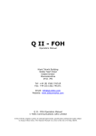
1
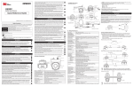
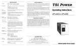
Service Manual Diagnostic Audiometer AD226 Part number 80671106 Valid from serial no. 746702 Contents Contents ......................................................................................................................................................................1 General Technical Specifications .............................................................................................................................2 Specification of input/output connections...........................................................................................................3 Calibration properties .........................................................................................................................................4 Survey of reference values for pure tone audiometer calibration ......................................................................4 Disassembly ................................................................................................................................................................6 Electrical Assembling Instrument .......................................................................................................................6 Schematics ..................................................................................................................................................................7 Block Diagram ....................................................................................................................................................7 Main board Diagram ...........................................................................................................................................8 Component Index ...................................................................................................................................13 Keys and Led’s Index.............................................................................................................................14 Component Partlist.................................................................................................................................15 Connector Board A Diagram ............................................................................................................................18 Component Index and Partlist................................................................................................................19 Connection Board B Diagram...........................................................................................................................20 Component Index and Partlist................................................................................................................21 Fuse PCB .........................................................................................................................................................22 Calibration Procedure ..............................................................................................................................................23 Service, adjustment and repair.........................................................................................................................23 Equipment for adjustment ......................................................................................................................23 Hardware Calibration........................................................................................................................................23 Calibration of Attenuator in channel 1....................................................................................................23 Calibration of Attenuator in channel 2....................................................................................................24 LCD angle adjustment............................................................................................................................25 Software Calibration .........................................................................................................................................25 General Description ...............................................................................................................................25 Tone Calibration .....................................................................................................................................25 Narrow Band Calibration ........................................................................................................................25 White Noise Calibration..........................................................................................................................26 Appendix A Technical Description of the RS232 Interface version 2.00 ..............................................................1 General Specification .........................................................................................................................................1 Control Wires......................................................................................................................................................2 Communication...................................................................................................................................................3 Audiological Information .....................................................................................................................................4 Test Results........................................................................................................................................................5 Controlling the AD226 ........................................................................................................................................6 AD226 Status .....................................................................................................................................................7 EEPROM Control ...............................................................................................................................................9 Programming Tips ....................................................................................................................................9 AD226 OnLine ....................................................................................................................................................9 Examples of Transmission .......................................................................................................................9 Window Routines in C++..................................................................................................................................10 Transmit Data from PC to Instrument ....................................................................................................10 Receive Data from Instrument ...............................................................................................................11 Appendix B Setting of Set-up items .........................................................................................................................1 Introduction.........................................................................................................................................................1 Set-up Items .......................................................................................................................................................1 Set-up item 3 CRC Check.....................................................................................................................2 Set-up item 8 Bekesy Deviation ............................................................................................................3 Set-up item 13 Buzzer...........................................................................................................................4 Set-up item 18 Bone Type ....................................................................................................................5 Set-up item 22 ABLB Pulse Time..........................................................................................................6 Set-up item 27 dB Value .......................................................................................................................7 Set-up Item 32 OSHA Level..................................................................................................................8 Appendix AD226 U Update News..............................................................................................................................1 AD226 Service Manual 1 General Technical Specifications Medical CE-mark: The CE-mark indicates that Interacoustics A/S meets the requirements of Annex II of the Medical Device Directive 93/42/EEC. Approval of the quality system is made by TÜV - identification no. 0123. IEC 60601-1, Class I, Type B (using UPS400 external power supply) IEC 60601-1-2 EMC: IEC 60645-1/ANSI S3.6 , Type 3 Tone audiometer Audiometer: UPS400 External power supply Power: See description in separate Service Manual 2xT1A + 1xT2A located on PCB Fuses: Operation environment: Temperature: 15 – 35 C 30 – 90% Rel. Humidity: Transport temperature:: -20-50°C 0-50°C Storage temperature: Warm up time: 3 minutes at room temperature (20 C). Standards: Safety: Functions Signal sources: Tone: Masking: Inputs: Outputs: Pat. response Power UPS400 Earphone Right / Left: Bone conductor: Insert masking phone MTP10: Printer: RS232 11 pure tone and warble test frequencies in the range of 125 – 8000Hz Narrow band noise, in 11 bands. White noise. Connection for patient response switch. Response lamp will light when activated. Connection for external power supply. Can be selected to be either standard earphones or insert phones by pressing shift Right/Left. Masking in Right or Left earphone can be selected. For use of CIR22. Use of MTP10 as printer device Laser printer with HP GL2 language Ink jet or matrix printer using IBM mode (optional) Desk jet printers using HP PCL L3 language (optional) Input/output for computer communication. See separate section in Service Manual for programming details Operator to patient communication. 10 – 110 dB continuously adjustable on the operation panel Patient Communication: Talk Forward: Attenuator: -10 to 120 dB in 1 or 5 dB steps for tone and speech. The upper 20 dB is accessed by pressing the +20 dB button. 0 – 110 dB in 1 or 5 dB steps for masking noise. Silent touch switch for soft presentation of signals. Tone lamp will light when activated. Tone is presented by activation of Tone Switch. Manual: Tone is interrupted by activation of Tone Switch. Reverse: Single pulse or automatic pulsing with selectable on/off times of Pulse: 250 – 5000ms. Patient controlled Hughson-Westlake test according to ISO 8253-1 with automatic storing of the threshold values in the internal memory. Patient response is open for 2 seconds after signal presentation. 2 out of 3 or 3 out of 5 correct responses can be selected. Pure tone or narrow band stimulation. Fixed frequency. Continuous and pulsed tone. If selected, it will indicate end of automatic test. With automatic score calculation (5 dB included for SISI: familiarisation). Binaural pure tone or speech stimulation. Stenger: Tone Switch: Tone presentation: Auto Threshold: Békésy: Buzzer: Special test types: AD226 Service Manual 2 Store Synchronous Masking: Channel 2 options: Tone in noise. Langenbeck When activated, the displayed values for AC L/R, BC L/R are stored in the internal memory. Stored values can be printed out on a printer if connected. Locks Channel 2 attenuator to Channel 1 attenuator. Output of Channel 2 can be set up to be either Narrow Band or White noise. Frequencies and maximum intensities Frequency Air conduction TDH39 Hz 125 250 500 750 1000 1500 2000 3000 4000 6000 8000 dB HL 90 110 120 120 120 120 120 120 120 120 110 EAR-Tone 3A dB HL 90 105 110 115 120 120 120 120 115 100 95 Bone conduction B71 Insert Masking NB/WN dB HL -45 65 70 70 70 75 80 80 55 50 dB HL -105 110 110 110 110 110 110 105 95 90 Specification of input/output connections Inputs Power UPS400 Patient response Connector type DIN, 5 pole Electrical properties Pin 1 and 2: Pin 3: Pin 4: Pin 5: Jack, 6.3mm stereo Handheld switch: 0V +5V -12V +12V Switches 5V to the logic input. (The switch current is 40mA) Outputs: Phones, Left/ Right Jack, 6.3mm mono Insert masking phone Voltage: Up to 5.5V rms. by 10Ω load Min. load impedance: 5Ω Jack, 6.3mm mono As for Phones, Left/Right Jack, 6.3mm mono Voltage: Up to 5.5V rms. by 100Ω load Min. load impedance: 100Ω Data I/O: RS232C 9 pole Cannon MTP10 Printer 9 pole Cannon 25 pole Cannon Bone conductor RS232 serial port for communication Serial port Parallel port See appendix A in service manual for detailed information For use of MTP10 as printing device. Standard connection for laser printer, using HPGL2 language. By addition of a built-in adapter (IPA26), the range of printers are increased: IPA26 is not longer available. Desk jet printer, using HP PCL L3 language. Matrix and Inc Jet printers using IBM mode. Other electrical specifications: Warble 5 Hz sine, ±5% modulation AD226 Service Manual 3 Calibration properties Telephonics TDH39 with a static force of 4.5N ±0.5N Radioear B71 with a static force of 5.4N ±0.5N ExAxR Tone 3A (Option) CIR22 (Option) Calibrated Transducers: Earphones: Bone conductor: Insert phones: Insert masking phone: Accuracies: Generally the instrument is made and calibrated to be within and better than the tolerances required in the specified audiometer standards: Frequency: ±1% Pure tone levels: ±3 dB for 125 – 4000Hz ±5 dB for 6000 – 8000Hz Tone calibration standards and spectral properties: Earphones Pure tone: Narrow band noise: − Spectral properties: White noise: − Spectral properties: Bone conductor Pure tone: Insert phones Pure tone: Narrow band noise: − Spectral properties: Insert masking phone White noise: − Spectral properties: Narrow band noise: − Spectral properties: White noise: − Spectral properties: ISO 389-1/ ANSI S3.6 for TDH39. ISO 389-1 / ANSI S3.6 + ISO 389-4 values IEC 60645-1, Narrow band noise SPL IEC 60645-1, White noise ISO 389-3 / ANSI S3.6. Valid for placement on the human mastoid ISO 389-2 ISO 389-2+ ISO 389-4 values IEC 60645-1, Narrow band noise, electrically measured. SPL IEC 60645-1, White noise, electrically measured. ISO 389-2 + ISO 389-4 values IEC 60645-1, Narrow-band noise, electrically measured. SPL IEC 60645-1, White noise, electrically measured. Survey of reference values for pure tone audiometer calibration Freq. [Hz] 125 250 500 750 1000 1500 2000 3000 4000 6000 8000 ISO 389-1 ANSI S3.6 (TDH39) (TDH39) [dB re. 20 µPa] 45,0 25,5 11,5 7,5 7 6,5 9 10 9,5 15,5 13 [dB re. 20 µPa] 45 25,5 11,5 8 7 6,5 9 10 9,5 15,5 13 ISO 389-4 ISO 389-3 ANSI S3.6 (ISO 8798) (ISO 7566) (NB (BC) (BC) masking) [dB re. 20 [dB re. 1µN] [dB re. 1µN] µPa] 4 4 67 67 4 58 58 5 48,5 48,5 6 42,5 42,5 6 36,5 36,5 6 31 31 6 30 30 5 35,5 35,5 5 40 5 40 ISO 389-2 (Insert) ISO 389-7 Free field (FF) ISO 389-7 Diffuse-field (FF) [dB re. 20 µPa] 26 14 5,5 2 0 2 3 3,5 5,5 2 0 [dB re. 20 µPa] 22,0 11,0 4,0 2,0 2,0 0,5 -1,5 -6,0 -6,5 2,5 11,5 [dB re. 20 µPa] 22,0 11,0 3,5 1,0 0,5 -1,0 -1,5 -4,0 -5,0 -0,5 5,5 Coupler types used by calibration − − − TDH39 is calibrated using a 6cc acoustic coupler made in accordance to IEC 303 Insert phones are calibrated using a 2cc acoustic coupler made in accordance to IEC 126 Bone Conductor is calibrated using a mechanical coupler made in accordance to IEC 373 AD226 Service Manual 4 General properties for earphones Sound attenuation values for earphones Frequency Attenuation EAR-Tone 3A TDH39 with MX41/AR or PN 51 cushion [Hz] [dB] [dB] 125 160 200 250 315 400 500 630 750 800 1000 1250 1500 1600 2000 2500 3000 3150 4000 5000 6000 6300 8000 3 4 5 5 5 6 7 9 11 15 18 21 26 28 31 32 29 26 24 32.5 36 37.5 36.5 33 39.5 42.5 General about Specifications Interacoustics continuously strive to improve the products and their performance. Therefore the specifications can be subject to change without notice. The performance and specifications of the instrument can only be guarantied if it is subject to a technical maintenance at least once a year. This should be made by a workshop, authorised by Interacoustics. Questions about representatives and products may be sent to: Interacoustics A/S Phone: +45 63713555 Drejervaenget 8 Fax: +45 63713522 DK 5610 Assens email: [email protected] Denmark http: www.interacoustics.com AD226 Service Manual 5 Disassembly Electrical Assembling Instrument I06013601 AD226 Service Manual 6 Schematics Block Diagram 0 S X X=CHANNEL N0. CBA AA_X X=CHANNEL No. 000 001 010 011 100 101 110 111 3210 0000 0001 0010 0100 1000 Talk Forward DSP -20dB - 0dB - 5dB -10dB -15dB Left Right Bone Insert Masking FF1 FF2 Reset BOOT Left EPROM OUTPUT 0 - 120dB 0 - 20dB +20dB ATT. FIX ATT. CH1 SWITCH 12KHz LPF CH1 Right STEREO DSP CODEC 2186 PCM3001 AA3_1 AA0_1 AA2_1 +20dB_1 OS1C OS1A OS1B AA1_1 IC61 Bone OUTPUT 0 - 120dB 0 - 20dB +20dB ATT. FIX ATT. CH2 SWITCH 12KHz LPF AA3_2 DUAL DAC AA2_2 AD7249 AA0_2 CH2 +20dB_2 Insert Masking OS2C OS2A OS2B AA1_2 VDD Pat. Response EPROM Orange EEPROM GND LCD Angel Adjust DUAL PORT RAM CPU RS232 Z180 Green VDD MTP10 PRINTER PARALLEL PRINTER 5450 KEYBOARD LIGHT KEYBOARD TONE SWITCH Tone On Organization Interacoustics a/s Title AD226 Blockdiagram Document Number Brightness Control Sheet Date 1 of 1 xd bl 0005 00001 Rev MBA Wednesday, April 12, 2000 Page . AD226 Service Manual 7 VDD VDD VDD R16 10K R154 4K75 IC9 IC10 d0 d1 d2 d3 d4 d5 d6 d7 21 22 1 44 43 42 3 2 D0 D1 D2 D3 D4 D5 D6 D7 c1 27 28 26 INT IEI IEO c3 c7 c5 a1 a0 4 39 40 41 5 7 CE RD IORQ M1 C/D B/A c2 29 CLK 6 12 24 25 NC NC NC NC ADDR. 44-47 PA0 PA1 PA2 PA3 PA4 PA5 PA6 PA7 ARDY ASTB 17 16 15 14 11 10 9 8 20 18 PB0 PB1 PB2 PB3 PB4 PB5 PB6 PB7 BRDY BSTB 31 32 33 34 35 36 37 38 23 19 AA0_1 AA1_1 AA2_1 AA3_1 AA0_2 AA1_2 AA2_2 AA3_2 Page4 Page4 Page4 Page4 Page4 Page4 Page4 Page4 VDD OS1A Page5 OS1B Page5 OS1C Page5 OS2A Page5 OS2B Page5 OS2C Page5 TONE Page2 PAT.RESP. Page2 VDD d0 d1 d2 d3 d4 d5 d6 d7 21 22 1 44 43 42 3 2 D0 D1 D2 D3 D4 D5 D6 D7 c1 27 28 26 INT IEI IEO c3 c7 c5 a1 a0 4 39 40 41 5 7 CE RD IORQ M1 C/D B/A c2 29 CLK 6 12 24 25 NC NC NC NC VDD VDD VSS 30 13 C15 100n Z84C20 IC11 ADDR. 48-4B PA0 PA1 PA2 PA3 PA4 PA5 PA6 PA7 ARDY ASTB 17 16 15 14 11 10 9 8 20 18 PB0 PB1 PB2 PB3 PB4 PB5 PB6 PB7 BRDY BSTB 31 32 33 34 35 36 37 38 23 19 dB1A Page2 dB1B Page2 LCLK Page2 SDATA Page2 VDD 21 22 1 44 43 42 3 2 D0 D1 D2 D3 D4 D5 D6 D7 c1 27 28 26 INT IEI IEO c3 c7 c5 a1 a0 4 39 40 41 5 7 CE RD IORQ M1 C/D B/A c2 29 CLK 6 12 24 25 NC NC NC NC dB2A Page2 dB2B Page2 ee0 ee1 ee2 ee3 VDD VDD VDD VSS d0 d1 d2 d3 d4 d5 d6 d7 30 13 C16 100n Z84C20 GND R155 4K75 IC42 ADDR. 4C-4F PA0 PA1 PA2 PA3 PA4 PA5 PA6 PA7 ARDY ASTB 17 16 15 14 11 10 9 8 20 18 PB0 PB1 PB2 PB3 PB4 PB5 PB6 PB7 BRDY BSTB 31 32 33 34 35 36 37 38 23 19 TSW Page2 SHIFT Page2 +20dB_2 Page5 +20dB_1 Page5 ROW0 Page2 ROW1 Page2 ROW2 ROW3 Page2 VDD COL0 COL1 COL2 COL3 COL4 COL5 COL6 COL7 Page2 Page2 Page2 Page2 Page2 Page2 Page2 Page2 VDD d0 d1 d2 d3 d4 d5 d6 d7 21 22 1 44 43 42 3 2 D0 D1 D2 D3 D4 D5 D6 D7 c1 27 28 26 INT IEI IEO c3 c7 c5 a1 a0 4 39 40 41 5 7 CE RD IORQ M1 C/D B/A c2 29 CLK 6 12 24 25 NC NC NC NC VDD 30 13 VDD VSS C9 100n Z84C20 ADDR. 50-53 PA0 PA1 PA2 PA3 PA4 PA5 PA6 PA7 ARDY ASTB 17 16 15 14 11 10 9 8 20 18 PB0 PB1 PB2 PB3 PB4 PB5 PB6 PB7 BRDY BSTB 31 32 33 34 35 36 37 38 23 19 PD0 PD1 PD2 PD3 PD4 PD5 PD6 PD7 RC3,16 PSTROBE BUSY PE -PERR PB4 Page2 PB5 Page2 DSP dc1 Page3 VDD VDD 30 13 VDD VSS C160 100n Z84C20 MEB-12C-5 VDD R156 1K5 LS1 GND T10 BC847 GND GND GND d[0..7] DATA[0..7] Page2,3 ee[0..3] c[0..8] CNTRL.[0..8] Page3,5 VDD 5 X 10K0 R5 R4 R6 R7 D000-DFFF CSDSP Page3 IC17,51 X1 12.288MHz R8 a[0..19] C2 12p 5% c1 VDD c3 C1 12p 5% VDD VDD VDD c4 IC6 c7 ee0 c8 VDD C6 100n MP1 R1 10K VDD 3 1 + C3 68u 20% VDD SENSE RESIN CT REF c0 8 R2 301 RES RES GND C5 22n 10% 8 9 10 11 12 c1 c0 5 6 4 TL7705A C4 100n GND R61 c2 200 68 67 66 65 63 62 60 5 7 6 61 13 64 c3 c4 c5 c6 c7 IC2 GND Page2 TSWCLK 24KHz 9 7 6 5 3 2 4 13 12 14 15 1 Q1 Q2 Q3 Q4 Q5 Q6 Q7 Q8 Q9 Q10 Q11 Q12 CLK RST c2 10 11 VDD 16 VSS 8 c8 GND VDD C8 100n GND GND R9 301 IC1 3 4 GND IC3 7 2 GND R3 10K COM1 Page5 Page5 Page5 Page5 TXA0 RXA0 RTS0 CTS0 GND 74HC4040 Printer TXA1 RXA1 XTAL EXTAL RESET NMI INT0 INT1 INT2 CLK RD WR M1 MREQ IORQ HALT WAIT BUSREQ BUSACK RFSH ST E 48 49 45 46 47 50 TXA0 RXA0 RTS0 CTS0 DCD0 CKA0/DREQ0 58 59 DREQ1 TEND1 54 51 53 56 CKA1/TEND0 TXA1 RXA1 RXS/CTS1 55 57 TXS CKS 52 TEST Z80180 14 15 16 17 19 20 21 22 23 24 25 26 27 28 29 30 31 32 a0 a1 a2 a3 a4 a5 a6 a7 a8 a9 a10 a11 a12 a13 a14 a15 a16 a17 A18/TOUT 33 a18 A19 35 a19 D0 D1 D2 D3 D4 D5 D6 D7 37 38 39 40 41 42 43 44 VCC 34 VSS VSS VSS VSS 1 2 18 36 a12 a13 a14 a15 a16 a17 a18 a19 5 6 7 4 3 2 1 15 A0 A1 A2 A3 A4 A5 A6 A7 c6 13 14 CE1 CE2 VDD O1 O2 O3 O4 12 11 10 9 VDD 16 GND 8 R157 1K VDD 100n a6 a5 c7 d0 d1 d2 d3 d4 d5 d6 d7 GND GND VDD GND IC5 A B C VDD VSS G1 G2A G2B Y0 Y1 Y2 Y3 Y4 Y5 Y6 Y7 VDD 15 14 13 12 11 10 9 7 VCC NC NC GND C12 100n VDD GND VEE1 VDD1 1 2 3 4 5 6 7 8 RC1 GND VDD1 C19 100n VDD C18 100n C17 100n R11 301 a18 R12 NP R13 0 IC7 a0 a1 a2 a3 a4 a5 a6 a7 a8 a9 a10 a11 a12 a13 a14 a15 a16 a17 12 11 10 9 8 7 6 5 27 26 23 25 4 28 29 3 2 30 31 A0 A1 A2 A3 A4 A5 A6 A7 A8 A9 A10 A11 A12 A13 A14 A15 A16 A17 A18 O0 O1 O2 O3 O4 O5 O6 O7 13 14 15 17 18 19 20 21 d0 d1 d2 d3 d4 d5 d6 d7 c3 VDD 22 24 1 CE OE VPP VEE1 d7 d6 d5 d4 GND GND IC8 VDD VCC 32 GND 16 C13 100n 74HC138 GND a0 a1 a2 a3 a4 a5 a6 a7 a8 a9 a10 a11 a12 10 9 8 7 6 5 4 3 25 24 21 23 2 A0 A1 A2 A3 A4 A5 A6 A7 A8 A9 A10 A11 A12 a14 1 NC GND VDD d0 d1 d2 d3 a0 CSAUTO c4 wr c3 rd 16 15 14 13 12 11 10 9 DIP16 R151 301 C11 a2 a3 a4 CS SK DI DO 8 7 6 5 GND CSLCD Page2 CBAR-D8 100n 1 2 3 16 8 6 4 5 1 2 3 4 93C66A C10 GND ee0 ee1 ee2 ee3 R10 301 IC4 A0 A1 A2 A3 A4 A5 A6 A7 A8 A9 A10 A11 A12 A13 A14 A15 A16 A17 ADDR.[0..19] Page2,3 RC1 I/O1 I/O2 I/O3 I/O4 I/O5 I/O6 I/O7 I/O8 11 12 13 15 16 17 18 19 d0 d1 d2 d3 d4 d5 d6 d7 CE2 CE1 WE OE 26 20 27 22 c4 c3 VCC GND 28 14 VDD C14 6264 M27C4001 0000-CFFF E000-FFFF C7 100n 100n GND R14 0 R15 NP VDD a13 GND POWER SUPPLY CONNECTIONS Digital Supply Analog Supply Interacoustics A/S VDD = +5V GND = 0V VDD1 = +12V VDDA = +5V GND = 0V VEE1 = -12V Date Constr. Approved Construction 091098 MBA IBP Revision 030506 PSC HBJ Title Mainboard 071 Partno. 69011001 NP = Not Present Drawingno. D02003702 Sheet 1 of 5 Page 8 VDD VDD VDD VDD VDD VDD VDD VDD VDD IC12 VDD VDD R19 4K75 R20 4K75 R21 4K75 R22 4K75 R24 4K75 S5 R18 4K75 2 1 AUTO THR. 2 R25 4K75 S4 1 S15 1 SHIFT Page1 R23 4K75 R26 4K75 S3 2 2 S2 1 2 BONE L S1 1 1 23 3 4 5 6 7 8 9 10 11 12 13 14 15 16 17 18 19 20 21 22 D11 2 D10 1dB 1 SYNCH EXT.RANGE LEFT RIGHT S9 S8 S7 S6 D9 MAN. D8 SHIFT GND 2 1 2 1 2 1 MAN/REV 1dB/5dB 2 PULSE SINGLE PULSE D7 BONE R 1 D6 BONE L/R AUT. THR. D5 SYNCH. D4 EXT.RANG. D3 LEFT D2 Page1 Page1 Page1 Page1 RIGHT ROW0 ROW1 ROW2 ROW3 S14 1 S13 2 1 TALK FWD. Page1 Page1 Page1 Page1 Page1 Page1 Page1 Page1 S12A 2 S12B 1 STORE 2 S11A 4 HZ. DEC. 3 1 HZ. INC. S11B 2 4 S10A 3 1 dB INC.CH2 NP dB DEC.CH2 NP S10B 2 4 dB DEC.CH1 NP IC41 VDD C159 GND 100n 16 VDD OSCI 7 GND OSCO 9 8 AIN BIN CIN DIN EIN FIN 1 14 3 12 5 10 GND P1 GND 4K7 A 2 D1 3V9 3 CH2 GND GND GND GND S16 C158 1n5 10% 1 2 3 VDD1 CH1 VDD RC3 GND PD0 PD1 PD3 47K5 R33 47K5 10K 3 C24 22p 5% 22p 5% D15 T2 BC847 LL4148 + C26 6u8 20% IC13A 4070 8 R39 10K 10 9 GND TSW Page1 10K C27 10n 5% C46 1u 10% 1 IN 4 SD OUT 2 ERR 5 PD6 BUSY +5V PB5 Page1 + C161 4u7 20% R62 49K9 GND PSTROBE -PERR PD2 PD4 PD5 PD7 PE PB4 Page1 16 15 14 13 12 11 10 9 Ekstern Printer GND GND GND 5 VDD LL4148 + C45 10u 20% R40 IC13C 4070 D16 GND GND 2 R38 10M 7 C23 D17 1 2 3 4 5 6 7 8 GND V2 LP2957 GND 1 GND J1 0 100n GND R37 10M R35 R31 14 47K5 R32 10K TSWCLK Page1 J2 NP 5% 3 10p C21 10n 5% T1 BC857 C25 C22 SDATA Page1 LCLK Page1 VDD 2K C20 10n 5% VDD R34 5dB 1 MC14490 VDD1 REV. D14 R17 S17 AOUT BOUT COUT DOUT EOUT FOUT MULTI PULSE D13 GND dB INC.CH1 NP BRIGHTNESS CONTROL 15 2 13 4 11 6 44 43 42 41 40 39 38 37 36 35 34 33 32 31 30 29 28 27 26 25 24 2 5450V VDD dB2A dB2B dB1A dB1B OUT18 OUT19 OUT20 OUT21 OUT22 OUT23 OUT24 OUT25 OUT26 OUT27 NC OUT28 OUT29 OUT30 OUT31 OUT32 OUT33 OUT34 ENABLE DATA CLK VSS 3 COL7 COL6 COL5 COL4 COL3 COL2 COL1 COL0 Page1 Page1 Page1 Page1 NC NC OUT17 OUT16 OUT15 OUT14 OUT13 OUT12 OUT11 OUT10 OUT09 NC OUT08 OUT07 OUT06 OUT05 OUT04 OUT03 OUT02 OUT01 BC VDD D12 GND 12 4 LL4148 11 6 GND R36 Kulfilm 22K Modstand 13 IC13B 4070 GND IC13D 4070 GND LCD DISPLAY IC4,10 Page1 CSLCD DISPLAY CONNECTION Touch Switch a[0..19] Page1 ADDR.[0..19] 14 Page1 PAT.RESP. VDD VDD D20 C29 100n 4pol D19 D21 R41 10K R42 R43 GND IC14D 74HC04 RC2 82R5 2 3 6 7 VEE1 GND GND 14 C156 100n VDD 10 Analog Supply VDD1 = +12V VDDA = +5V GND = 0V VEE1 = -12V GND 1 C31 10u 20% d0 d2 d4 d6 14 1 2 7 16 15 14 13 12 11 10 9 VDD a0 d1 d3 d5 d7 LCM-523 1 16 2 15 3 14 4 13 5 12 6 11 7 10 1 2 3 4 5 6 7 8 9 10 11 12 13 14 8 LCD BACKLIGHT TO DISPLAY N1 NP VSS VDD V0 RS R/W E DB0 DB1 DB2 DB3 DB4 DB5 DB6 DB7 N2 NP VDD 9 VDD D23 R161 NP R162 0 R163 0 R164 NP R46 5R6 Metalfilm Modstand Green R44 182 IC14F 74HC04 1 2 3 4 5 6 7 8 RC1 IC14A 74HC04 GND Tone CH1 Page1,3 DATA[0..7] d[0..7] GND Interacoustics A/S 14 VDD = +5V GND = 0V OUT a1 GND D22 GND TONE Page1 12 7 Digital Supply 13 100n 3 4 Date Constr. Approved Construction 091098 MBA IBP Revision 030506 PSC HBJ R45 182 7 POWER SUPPLY CONNECTIONS VDD IN IN IN IN GND VEE-ADJ C30 IC14E 74HC04 14 7 11 P2 10K V1 79L05 82R5 Orange 8 7 9 D18 C32 100n VDD GND 100n 1 2 3 4 Patient response 14 7 IC14C 74HC04 Pat. Response GND MX1 5 6 + C28 5 GND VDD VEE-ADJ a0 a1 CE LCD d0 d1 d2 d3 d4 d5 d6 d7 IC14B 74HC04 Title Partno. NP = Not Present Mainboard 071 69011001 Drawingno. D02003702 Sheet 2 of 5 Page 9 C35 X3 12.288MHz 100n C47 C51 100n dd21 R58 1K dd20 R59 1K GND GND GND dd18 R131 1K dd17 R63 1K dd16 R60 1K GND GND GND VDD GND R30 100K GND GND 100K R52 10K 91 96 14 PWD PWDACK dc1 7 GND GND EXTGND EXTGND EXTGND EXTGND EXTGND EXTGND EXTGND EXTGND EMS EE ECLK ELOUT ELIN EINT EBR EBG ERESET 45 46 47 48 49 50 51 53 43 GND dc5 dc3 VDD VDD 12 11 10 9 8 7 6 5 27 26 23 25 4 28 29 3 2 A0 A1 A2 A3 A4 A5 A6 A7 A8 A9 A10 A11 A12 A13 A14 A15 A16 22 24 31 1 CE OE PGM VPP 30 R27 200 C61 IC45 10 11 16 VCC 32 GND 16 8 GND CLK Q1 Q2 Q3 RST Q4 Q5 Q6 Q7 VDD Q8 Q9 Q10 GND Q11 Q12 4u7 20% 4 VrefL 4u7 20% 5 C38 100n 7 GND C59 470p 5% 9 7 6 5 3 2 4 13 12 14 15 1 C129 GND 74HC4040 9 15 VoutR 12 VCOM 11 VrefR 8 R_OUT Page4 C165 100p 1% GND 8 Cin-R 6 VinR VREF DSP 3 1 Cin+R 2 C52 10u 20% MP3 IC20A OP275 + GND 16 17 18 19 LRCIN BCKIN DIN DOUT 28 RSTB 27 26 25 FMT0 FMT1 FMT2 VDD 23 DGND 24 VccADC 2 GNDADC 3 VccDAC 14 GNDDAC 13 C56 220n GND VDDA L7 0 C57 220n GND MP11 C58 220n GND GND PCM3001 27C010 3 4 7 da0 da1 da2 da3 da4 da5 da6 da7 da8 da9 da10 da11 da12 da13 IC46B 74HC04 14 VDD1 dc5 C62 100n 10K MP9 7 da[0..13] DSP ADDRESS BUS 6 dd[8..23] 4 DSP DATA BUS c0 VREF DAC IC20B 5 14 dc[0..6] DSP CONTROL BUS 6 IC46C 74HC04 7 200 10K 5 GND R53 dc6 8 R51 VoutL 1u 10% IC46D 74HC04 GND NC C60 GND L8 0 VDD Cin-L C164 100p 1% dc2 10K R50 GND 9 GND 301 R49 dd8 dd9 dd10 dd11 dd12 dd13 dd14 dd15 13 14 15 17 18 19 20 21 O0 O1 O2 O3 O4 O5 O6 O7 Cin+L C55 470p 5% IC46E 74HC04 IC16 da0 da1 da2 da3 da4 da5 da6 da7 da8 da9 da10 da11 da12 da13 dd16 dd17 10 L_OUT Page4 reset c0 OP275 C63 reset VEE1 13 12 IC46F 74HC04 GND 100n GND 7 R48 64 63 62 61 58 VDD dd23 dd22 dd21 dd20 dd19 dd18 dd17 dd16 dd15 dd14 dd13 dd12 dd11 dd10 dd9 dd8 87 86 85 FL0 FL1 FL2 57 56 55 11 10 9 8 7 6 5 4 2 1 100 99 98 97 VDD R47 IWR/D7 IRD/D6 IAL/D5 IS/D4 IACK/D3 GND 84 83 82 81 79 78 77 76 75 74 73 72 70 69 68 65 D23 D22 D21 D20 D19 D18 D17 D16 D15 D14 D13 D12 D11 D10 D9 D8 C53 100n 10 VinL 14 100K VDD 1 7 R29 ADSP-2184 10% GND TFS0 RFS0 SCLK0 DR0 DT0 VDD IRQ2+PF7 IRQL1+PF6 IRQL0+PF5 IRQE+PF4 PF3 PF2[MODE C] PF1[MODE B] PF0[MODE A] 1u 100n 11 32 33 35 34 31 30 29 27 26 88 89 93 94 10K TFS1 RFS1 SCLK1 DR1 DT1 R28 IC15 38 39 42 40 37 dc1 IAD15/D2 IAD14/D1 IAD13/D0 IAD12/A13 IAD11/A12 IAD10/A11 IAD9/A10 IAD8/A9 IAD7/A8 IAD6/A7 IAD5/A6 IAD4/A5 IAD3/A4 IAD2/A3 IAD1/A2 IAD0/A1 A0 dc4 dc3 12 66 3 17 28 41 60 71 80 92 18 59 15 36 67 90 dc5 dc6 C128 + DSP dc1 Page1 IC19 C54 + dc1 VDD VDD EXTVDD EXTVDD EXTVDD EXTVDD dc2 XTAL CLKIN CLKOUT RESET BR BG BGH IOMS BMS DMS CMS PMS WR RD 22p 5% GND GND L1 - L6 0 14 13 16 44 52 54 95 24 21 22 25 23 19 20 22p 5% 8 100n GND 4 C50 GND 21 GND 22p 5% GND 100n 1K 1K 20 22p 5% C49 dd22 R57 dd19 R132 XTI C34 1K 14 C33 GND 100n dd23 R56 22 C37 X2 16.67MHz C48 100n CLKIO C36 XTO VDD IC17 7 8 9 10 11 12 13 14 15 16 da0 da1 da2 da3 da4 da5 da6 da7 da8 da9 d0 d1 d2 d3 d4 d5 d6 d7 27 28 29 30 31 32 33 34 D0R D1R D2R D3R D4R D5R D6R D7R D0L D1L D2L D3L D4L D5L D6L D7L 17 18 19 20 21 22 23 24 dd8 dd9 dd10 dd11 dd12 dd13 dd14 dd15 51 50 49 48 46 CSR R/WR BUSYR INTR OER 1 2 3 4 6 d_dms d_wr dc6 dc4 IRQ2 d_rd dc1 dc3 14 A0L A1L A2L A3L A4L A5L A6L A7L A8L A9L CSDSP Page1 c4 wr c3 rd c[0..8] CSL R/WL BUSYL INTL OEL C39 100n 0-10V 0 NP 7 R70 GND R55 R73 NP R71 0 +-5V 0-5V NP R74 VDD1 MIC. PRE.AMP. R64 4K75 D24 6V2 R65 4K75 GND + C40 100u 20% VDD1 3 GND R72 0 REFOUT REFIN 11 9 12 SCLK SDIN SYNC 6 10 7 CLR LDAC BIN/COMP 13 VDD RA 16 VOUTA 14 DCATT_1 Page4 VOUTB 4 DCATT_2 Page4 RB 3 AGND 5 MP2 GND C41 220n 20% GND GND C42 N3 NP MIC. NP IC21 1 2 VDD GND IDT7130SA20J NP 2 IC46A 74HC04 VDD 52 26 R69 R54 1 d[0..7] DATA[0..7] Page1,2 CNTRL.[0..8] Page1 A0R A1R A2R A3R A4R A5R A6R A7R A8R A9R 7 a[0..19] 45 44 43 42 41 40 39 38 37 36 R66 10K 2 100n VDD1 GND IC18 + C64 100n 6 - OP27 D25 LL4148 4 ADDR.[0..19] Page1 a0 a1 a2 a3 a4 a5 a6 a7 a8 a9 N4 NP D26 LL4148 + C65 10u 20% R67 10 C44 POWER SUPPLY CONNECTIONS DGND VSS GND AD7249 GND 1K GND 15 GND R68 GND 8 GND 10n 5% C66 100n GND + C67 10u 20% VEE1 C43 Digital Supply VDD = +5V GND = 0V 100n VEE1 Analog Supply Interacoustics A/S GND Date Constr. Approved Construction 091098 MBA IBP Revision 030506 PSC HBJ GND VDD1 = +12V VDDA = +5V GND = 0V VEE1 = -12V Title Partno. NP = Not Present Mainboard 071 69011001 Drawingno. D02003702 Sheet 3 of 5 Page 10 100p 44K2 5K R149 1K N6 8 R83 7 10K 5 R85 3K01 4 IC23B DGND NC AGND AGND AGND AGND VDD VEE IC25A SSM2404 3 GND OP275 GND R93 SW/C 1 SW/I SW/O 3 C85 100p R96 1K 6 SW/C 10 SW/I SW/O VDD1 8 C86 SSM2404 16 SW/C 20 SW/I 13K3 SW/O GND 100n MP4 C68 100n SSM2404 3 GND 100n GND C172 C169 10n 5% 3 7 8 12K4 GND GND IC47B 7 6 1K5 OP275 5 C72 OP275 1u 10% GND R86 GND IC24 THAT2181S 1 18K2 8 6 GND R87 3K92 P7 50K 100n VEE1 GND C79 100n VEE1 GND GND R104 C94 1u N7 N8 VDD1 C96 100n 17 4 7 2 9 12 19 4 1K IC30A SSM2404 R107 3K40 C95 4u7 20% 3 GND OP275 + GND SW/C -5dB 1 SW/I 2K21 VEE1 R115 3 C105 100p R118 1K SW/C 10 SW/I SW/O VDD1 8 C106 SSM2404 16 20 13K3 SW/C SW/I 4K99 SW/O 3 GND OP275 12K4 C175 10n 5% GND GND C92 IC48B 6 C174 7 5 GND OP275 1u 10% R108 18K2 1 GND IC29 THAT2181S 8 VEE1 100n GND C162 10u 20% 6 VDD1 GND C107 IC44 2 3 100n VEE1 3 7 100n 7 8 3 8 1K5 1 82K5 C176 1n 1% R139 GND ATOUT_2 Page5 OP27 C183 GND OP27 4 21K R141 100n GND 4 GND IC27B OP275 C178 1n 1% 2 GND 5 IC48A 2 R140 1K5 GND 10K5 GND 6 SSM2404 + C102 10u 20% VDD1 6 30K1 C90 10n 5% R146 VDD1 C98 4 100n VEE1 7 R159 R116 GND 5 GND R158 21K 6 C89 VDD1 C173 C177 100n 100p 1% 4 R99 4K99 R103 R101 5K36 OP275 4 R98 10K C91 100p 1% 8 IC27A GND 1 2 3 VREF DSP R102 5K36 4 R97 10K MP5 C88 100n 8 Page3 R_OUT 100n VEE1 + VDD1 GND 100n IC31 2 18 -20dB R100 1% IC30E -15dB C97 6 4K75 Page1 AA3_2 GND SW/O SSM2404 IC30C Page1 AA2_2 100n 13 IC30B 5 R114 SW/O SSM2404 Page1 AA1_2 C104 IC28A GND 1 2 4 3K01 8 IC28B SW/I 1K1 -10dB 8 P6 R105 11 R113 DGND NC AGND AGND AGND AGND VDD VEE Gain OP275 7 SW/C 0dB R112 100n R152 10K 15 VDD1 1% IC30D Page1 AA0_2 C103 1K R150 GND 5 47p 5% 10% GND 6 C81 VEE1 44K2 5K + C93 68u 20% 100p 18K2 14 P5 C166 GND R89 Offset VREF DAC GND C182 R88 243K 10K MP6 OP27 VDD1 GND DCATT_2 Page3 IC43 2 3 100n VEE1 GND R153 7 R138 GND C163 10u 20% 7 C170 1n 1% 3 100n VEE1 4 82K5 100n 4 2 21K R137 C87 C80 4 GND IC22B OP275 IC47A GND 1 100n GND 2 5 R135 R136 1K5 6 C69 VEE1 GND 7 30K1 C70 10n 5% R133 C168 1n 1% 5 R77 4K99 6 8 5K36 8 OP275 R81 R134 21K ATOUT_1 Page5 OP27 GND 10K5 + C82 10u 20% VDD1 4 R76 10K R79 4 3 VREF DSP IC22A GND 1 VDD1 C171 C167 100n 100p 1% 4 2 4 R75 10K 8 L_OUT VDD1 C78 C71 100p 1% R80 5K36 Page3 + VDD1 R94 GND VEE1 GND 6 4 4K99 100n IC26 2 18 -20dB R78 1% SSM2404 IC25E -15dB C77 5 4K75 Page1 AA3_1 100n GND VEE1 13 IC25C -10dB R92 SW/O SSM2404 2K21 Page1 AA2_1 C84 IC23A GND 1 2 3K40 C75 4u7 20% + GND C76 100n 1K 4 OP275 6 R91 SW/I IC25B -5dB 8 P4 VDD1 4 7 2 9 12 19 Gain 10K DCATT_1 Page3 GND SW/C 11 1K1 Page1 AA1_1 100n GND R117 R90 C83 N5 R95 0dB 10% VDD1 + C73 68u 20% 1% 1u 15 7 C157 C74 14 P3 R82 17 Offset IC25D Page1 AA0_1 VREF DAC C184 R160 GND R110 3K92 P8 50K VEE1 243K GND C99 GND 100n VEE1 100n GND R111 18K2 C101 47p 5% VEE1 POWER SUPPLY CONNECTIONS Digital Supply Analog Supply Interacoustics A/S VDD = +5V GND = 0V VDD1 = +12V VDDA = +5V GND = 0V VEE1 = -12V Approved Date Constr. Construction 091098 MBA IBP Revision 030506 PSC HBJ Title Mainboard 071 Partno. 69011001 NP = Not Present Drawingno. D02003702 Sheet 4 of 5 Page 11 R125 OUTPUT SWITCH IC32C VDD1 11 SW/O + 3 VDDA C110 +20dB GND NC NC NC NC NC NC NC VDD VEE 8 VSS 7 VEE GND C111 GND GND 1K VEE1 R122 3 VDDA 16 VDD 8 VSS 7 VEE C113 100n GND GND_RIGHT GND_BONE SMD11A05 R127 10 GND_INSERT 4 x 100pF Chassis RL2 VEE1 3 4 RIGHT OUT SMD11A05 VDD1 C121 100p 2 VDD 3K01 RIGHT 1% D31 T5 MJD122 C123 220n 20% 22p 5% VDD1 C126 100n X0 X1 X2 X3 X4 X5 X6 X7 13 14 15 12 1 5 2 4 INH A B C 6 11 10 9 IC51 2 GND 3 R124 GND C127 C125 220n 20% C124 220n 20% OP27 GND T6 MJD127 GND R130 10 BONE 100n GND VEE1 + C100 10u 20% c[0..8] CNTRL.[0..8] Page1 GND_RIGHT 1K R109 4K75 RESET c0 100 GND 6 MDC3105LT1 T7 LL4148 R129 X 8 7 6 5 4 3 2 1 GND_LEFT 2 VDD GND R128 1K3 +20dB CH2 LEFT OUT 1 IC34 14K3 4 1 GND CH2 R123 C117 220n 20% T4 MJD127 100n GND C122 SW/O C118 220n 20% Mounted on the jacksocket. ( rearplate ) GND_LEFT 6 C112 + C120 R121 SW/C SW/I GND OP27 GND MX2 RL1 3 100 GND 6 Page1 OS1A IC32B 4u7 20% 3 Page1 OS1B SSM2402 ATOUT_2 Page4 INH A B C 6 11 10 9 IC50 2 Page1 OS1C 100n VEE1 MP8 X0 X1 X2 X3 X4 X5 X6 X7 13 14 15 12 1 5 2 4 4051 7 1 3 5 8 9 10 12 14 VDD GND 16 IC32A SSM2402 16 C109 100n 100n 4 X 1K3 VDD1 GND R126 IC33 14K3 +20dB CH1 2 C116 220n 20% C119 100n CH1 R120 R119 Page1 +20dB_2 T3 MJD122 7 SW/I C108 4u7 20% 22p 5% LEFT VDD1 SW/C SSM2402 ATOUT_1 Page4 C115 4 13 MP7 100p 1% 7 15 C114 4 Page1 +20dB_1 3K01 VEE1 GND R142 3K01 GND VDD1 4051 C130 100p 1% C131 22p 5% T8 MJD122 Page1 OS2C Page1 OS2B Page1 OS2A VDD1 C132 220n 20% C135 100n GND R143 BONE OUT 7 IC52 2 3 100 GND 6 GND C133 220n 20% OP27 4 VDD GND C136 T9 MJD127 VDD1 C134 220n 20% R144 10 GND_BONE R147 10K 100n T1I T2I 12 9 RXA1 C145 1u C146 1u 10% 10% R1O R2O T1O T2O 14 7 R1I R2I 13 8 16 4 3 2 1 GND Printer 1 C1+ VDD 3 C1- V+ 2 C147 1u 10% 4 C2+ V- 6 C148 1u 10% 5 C2- GND VDD 11 10 Page1 RXA0 Page1 CTS0 12 9 1 C149 1u 10% C150 1u 10% 3 C151 MAX202 1u 10% GND T1O T2O 14 7 R1O R2O R1I R2I 13 8 C1+ VDD 16 T1I T2I C1- 15 GND 10 9 8 7 6 5 4 3 2 1 IC40 Page1 TXA0 Page1 RTS0 V+ 4 C2+ V- 5 C2- GND 2 6 VDD GND C153 1u 10% DSR RXD C142 100n 100n 100n GND Power Supply VDD1 GND VEE1 VDD GND D29 NP Digital Supply GND D33 SL23 D30 NP Analog Supply V3 INS OUT C139 100n GND 8 VDD = +5V GND = 0V C143 10n 5% VDD1 = +12V VDDA = +5V GND = 0V VEE1 = -12V IN OUT Chassis 100n 1 MP10 C180 + C144 10u 20% HF3 GND Chassis 100n Interacoustics A/S GND C181 GND HF1 GND 78L05 GND GND GND GND POWER SUPPLY CONNECTIONS D32 SL23 MX3 External GND 6 OP27 GND VDDA 2 3 6 7 VEE1 6 5 4 3 2 1 IC53 GND_INSERT C179 From INSERT C138 100n VDD1 VDD1 GND VDD1 VEE1 C141 1% 1K96 3 GND C140 GND R145 GND 15 GND VDD1 100p 2 MAX202 VDD C137 TXD CTS DTR VDD GND C155 100n 10% C154 1u 10% VEE1 GND To PC VDD C152 1u GND MX5 7 11 10 TXA1 MX4 4 IC39 VEE1 R148 2K GND GND HF5 Chassis 100n VEE1 Approved Date Constr. Construction 091098 MBA IBP Revision 030506 PSC HBJ Title Mainboard 071 Partno. 69011001 NP = Not Present Drawingno. D02003702 Sheet 5 of 5 Page 12 Component Index AD226 Service Manual 13 Component Partlist Assembled Board PCA 51001902 Quantity Part Reference Part Number Value Tolerance 2 4 2 1 1 1 1 2 3 1 2 4 2 3 86 A1 A2 A3 A4 A5 A6 A7 A8 A9 A10 A11 A12 A13 A14 A15 A16 A17 A18 A19 A20 A21 RC1 RC2 RC3 C1 C2 C3 C73 C93 C4 C6 C7 C8 C9 C10 C11 C12 C13 C14 C15 C16 C17 C18 C19 C25 C28 C29 C30 C32 C35 C36 C37 C38 C39 C42 C43 C49 C50 C51 C53 C54 C62 C63 C64 C66 C68 C69 C76 C77 C78 C79 C80 C83 C84 C86 C87 C88 C89 C96 C97 C98 C99 C103 C104 C106 C107 C109 C110 C111 C113 C119 C120 C126 C127 C135 C136 C138 C139 C140 C141 C142 C155 C156 C159 C160 C171 C172 C173 C174 C179 C180 C181 C182 C183 C184 45108401 35500201 36309201 36309301 36307301 36307501 36307401 36307101 36307201 36307701 75800801 75801301 61420301 61000301 61401101 Labels pertinaxskive tast_0 tast_0 tast_1 tast_1 tast_1 tast_1 tast_2 tast_2 DIP32 DIP16 12p 68u 100n 5% 20% 10% 1 9 1 9 1 11 C5 C20 C21 C27 C44 C70 C90 C143 C169 C175 C22 C23 C24 C33 C34 C47 C48 C115 C122 C131 C26 C31 C45 C52 C65 C67 C82 C100 C102 C144 C162 C163 61400101 61401001 61415301 61400501 61002701 61000201 22n 10n 10p 22p 6u8 10u 10% 5% 5% 5% 20% 20% 1 13 C40 C41 C56 C57 C58 C116 C117 C118 C123 C124 C125 C132 C133 C134 C46 C72 C74 C92 C94 C128 C129 C145 C146 C147 C148 C149 C150 C151 C152 C153 C154 C55 C59 C60 C61 C75 C95 C108 C112 C161 C71 C85 C91 C105 C114 C121 C130 C137 C157 C164 C165 C166 C167 C177 C81 C101 C158 C168 C170 C176 C178 D1 D2 D3 D4 D5 D6 D7 D8 D9 D10 D11 D12 D13 D14 D15 D16 D17 D25 D26 D31 D18 D19 D20 D21 D22 D23 D24 D32 D33 HF1 61003001 61401201 100u 220n 20% 20% 61401601 1u 10% 61401501 61000501 61400201 470p 4u7 100p 5% 20% 1% 61407901 61400901 61401801 61700101 71700101 61700201 71700301 71700201 61700501 61700301 47p 1n5 1n 3V9 LED LL4148 LED LED 6V2 SL23 Earthgnd 5% 10% 1% 17 2 7 14 2 1 4 1 13 6 4 2 1 2 1 AD226 Service Manual 15 Keys and Led’s Index AD226 Service Manual 14 Quantity Part Reference Part Number Value Tolerance 62000101 62002601 62000201 62000301 62000401 62000901 62000501 72000101 62000601 62031601 62000801 62000701 62001001 62001101 62001201 62001401 62002101 72700501 62001701 62002901 72000201 62008801 62001601 62002201 62002301 60400101 60204701 76300501 74000101 Earthgnd Earthgnd Z80180 Z84C20 5450V 4070 74HC04 74HC4040 ADSP-2184 27C010 IDT7130SA20J OP27 PCM3001 OP275 AD7249 THAT2181S SSM2404 TL7705A SSM2402 CBAR-D8 74HC138 93C66A M27C4001 6264 4051 MAX202 MC14490 0 1% 0 1% MEB-12C-5 MP 1 1 1 4 1 1 2 2 1 1 1 9 1 7 1 2 2 1 1 1 1 1 1 1 2 2 1 8 8 1 11 HF3 HF5 IC1 IC10 IC11 IC9 IC42 IC12 IC13 IC14 IC46 IC2 IC45 IC15 IC16 IC17 IC18 IC26 IC31 IC43 IC44 IC50 IC51 IC52 IC53 IC19 IC20 IC22 IC23 IC27 IC28 IC47 IC48 IC21 IC24 IC29 IC25 IC30 IC3 IC32 IC4 IC5 IC6 IC7 IC8 IC33 IC34 IC39 IC40 IC41 J1 R13 R14 R54 R71 R72 R162 R163 L1 L2 L3 L4 L5 L6 L7 L8 LS1 MP1 MP2 MP3 MP4 MP5 MP6 MP7 MP8 MP9 MP10 MP11 2 1 1 1 1 1 2 2 2 28 MX1 MX4 MX2 MX3 MX5 P1 P2 P3 P5 P4 P6 P7 P8 R1 R3 R4 R5 R6 R7 R8 R16 R28 R31 R32 R39 R40 R41 R49 R50 R51 R52 R66 R75 R76 R95 R97 R98 R117 R147 R152 R153 75800201 75801101 75800601 75810901 73400101 73400201 63400201 63400301 63403101 60400201 4pol 8pol 6pol 10pol 4K7 10K 5K 1K 50K 10K 1% 6 2 16 R2 R9 R10 R11 R48 R151 R17 R148 R18 R19 R20 R21 R22 R23 R24 R25 R26 R64 R65 R92 R109 R114 R154 R155 R27 R53 R61 R29 R30 R47 R33 R34 R35 R36 R37 R38 R42 R43 R44 R45 60401401 60400901 60401101 301 2K 4K75 1% 1% 1% 60401801 60401701 60402501 70100101 60402601 60425201 60402801 200 100K 47K5 22K 10M 82R5 182 1% 1% 1% 5% 1% 1% 1% 3 3 3 1 2 2 2 AD226 Service Manual 16 Quantity Part Reference Part Number Value Tolerance 1 14 70106101 60403601 5R6 1K 5% 1% 1 4 4 4 2 2 5 2 4 2 2 2 2 2 2 2 2 3 2 4 5 2 1 2 2 12 R46 R56 R57 R58 R59 R60 R63 R68 R96 R118 R121 R124 R131 R132 R157 R62 R67 R127 R130 R144 R77 R78 R99 R100 R79 R80 R101 R102 R81 R103 R82 R104 R83 R105 R125 R128 R142 R85 R107 R86 R89 R108 R111 R87 R110 R88 R160 R90 R112 R91 R113 R93 R115 R94 R116 R119 R122 R120 R123 R126 R129 R143 R133 R159 R134 R135 R146 R158 R136 R138 R140 R141 R156 R137 R139 R145 R149 R150 RL1 RL2 S1 S2 S3 S4 S5 S6 S7 S8 S9 S13 S14 S15 60420301 60401301 60403001 60403101 60403201 60403301 60400701 60403401 60402401 60403501 60402701 60403701 60403801 60403901 60404001 60400801 60401601 60401201 60400401 60400301 60401901 60402301 60416601 70121901 64500101 36302001 1% 1% 1% 1% 1% 1% 1% 1% 1% 1% 1% 1% 1% 1% 1% 1% 1% 1% 1% 1% 1% 1% 1% 1 2 1 1 2 3 3 1 1 1 1 2 1 S12 S16 S17 SW1 T1 T2 T10 T3 T5 T8 T4 T6 T9 T7 V1 V2 V3 X1 X3 X2 51000301 73900101 Dummy 64600101 64600401 64600201 64600301 62002701 64300101 64300201 64300301 63201401 63201501 49K9 10 4K99 5K36 30K1 44K2 3K01 3K40 18K2 3K92 243K 1K1 2K21 13K3 10K5 14K3 1K3 100 82K5 21K 1K5 12K4 1K96 1K SMD11A05 SW PUSHBUTTON XA4 CODESWITCH DIGITAST SYM BC857 BC847 MJD122 MJD127 MDC3105LT1 79L05 LP2957 78L05 12.288MHz 16.67MHz 1.4% AD226 Service Manual 17 Left Right J1 Phonejack Stereo SW GND_Left J2 Phonejack Stereo SW LEFT Model 071: Pat.Response Model 093 = NP Bone GND_Right J3 Phonejack Stereo SW RIGHT GND_Bone BONE J5 Phonejack Stereo SW +5V PAT_RES C1 22n C2 100p C3 22n Chassis C4 100p C5 22n Chassis C6 100p C10 22n Chassis C11 22n Chassis +5V Model 071: InsertMask. Model 093: Pat.Respose CO3 J4 Phonejack Stereo SW PAT_RES 1 2 3 4 4pol Mainboard 071: MX1 Display Board 093: MX3 GND_INS R1 0 R2 NP INS R3 0 R4 NP C7 22n C8 100p PAT_RES +5V C9 NP Chassis CO1 1 2 3 4 5 6 7 8 GND_INS INS GND_Bone BONE GND_Right RIGHT GND_Left LEFT CO2 1 2 3 4 5 6 GND_Bone BONE GND_Right RIGHT GND_Left LEFT N1 N2 Chassis Presskrue-3mm Lodde ø NP 8pol Mainboard 071: MX2 Model 093 = NP Interacoustics A/S Model 071 = NP Mainboard 093: MX1 Approved Date Constr. Construction 080403 PSC TKJ Revision 121250 PSC TKJ Rear Panel 071/093 Partno. 69011301 Sheet 1 of 1 Title NP = Not Present Drawingno. D02002901 071 Page 18 Component Index and Partlist Quantity 2 6 4 1 1 5 2 Part Reference A1 A2 C1 C3 C5 C7 C10 C11 C2 C4 C6 C8 CO1 CO3 J1 J2 J3 J4 J5 R1 R3 Part Number 65651 60658 59751 42457 42455 60120 60324 Value Labels 22n 100p 8pol 4pol Phone jack Stereo SW 0 Tolerance 10% 1% 1% AD226 Service Manual 19 Mainboard 071: RC3 Mainboard 093: NP N3 N5 N2 N4 N1 N11 N12 N14 N15 N17 N18 3 1 5 2 4 1 2 4 5 7 8 1 2 3 4 5 6 7 8 9 10 11 12 13 14 15 16 CO1 16pol C26 22n C1 1n C27 22n C2 1n C28 22n C3 1n C4 1n C5 1n C6 1n C7 1n C8 1n C9 1n C10 1n C11 1n C12 1n C13 1n C14 1n C15 1n C16 1n C17 1n C18 1n 1n C21 1n Mainboard 071: MX3 Mainboard 093: MX4 CO3 Mainboard 071: MX4 Mainboard 093: MX5 CO4 10pol 4 3 2 1 10 9 8 7 6 5 4 3 2 1 Mainboard 071: MX5 Mainboard 093: MX2 C29 1n C38 1n C30 1n C39 1n C31 1n C40 1n C32 1n C41 1n C33 1n C42 1n C34 1n C43 1n C35 1n C44 1n C36 1n C45 1n C37 1n C46 1n CO5 4pol 1n C23 1n C24 1n 1n CO2 25pol PRINTER Chassis 9pol Chassis CO7 9pol 11 CO6 RS232 31 30 10 1 14 2 15 3 16 4 17 5 18 6 19 7 20 8 21 9 22 10 23 11 24 12 25 13 1 6 2 7 3 8 4 9 5 Chassis 1 6 2 7 3 8 4 9 5 Chassis Chassis 10 C25 NC GND +5V -12V GND +12V 1n C20 C22 1 2 3 4 5 6 Chassis 11 C19 6pol Model 041 Chassis Chassis Interacoustics A/S Chassis Chassis Date Constr. Approved Construction 080403 PSC TKJ Revision 121205 PSC TKJ Rear Panel B 071/093 Partno. 69011401 Sheet 1 of 1 Title NP = Not Present Drawingno. D02003501 071 Page 20 Component Index and Partlist Quantity Part Reference 2 A1 A2 43 C1 C2 C3 C4 C5 C6 C7 C8 C9 C10 C11 C12 C13 C14 C15 C16 C17 C18 C19 C20 C21 C22 C23 C24 C25 C29 C30 C31 C32 C33 C34 C35 C36 C37 C38 C39 C40 C41 C42 C43 C44 C45 C46 Part Number Value Tolerance 65651 Labels 66241 1n 10% 3 1 1 1 1 1 2 60658 42461 65898 42456 42458 42455 62179 C26 C27 C28 CO1 CO2 CO3 CO4 CO5 CO6 CO7 22n 10% 16pol 25pol 6pol 10pol 4pol 9pol AD226 Service Manual 21 Fuse PCB Fuses: 2x 1A 125V Slo-Blo part number 63600801 1x 2A 125V Slo- Blo part number 63601001 AD226 Service Manual 22 Calibration Procedure Service, adjustment and repair This instrument can be serviced, adjusted and repaired without loosening the validity of the CE-marking provided the measuring equipment used is fulfilling the demands below, the adjustment procedures are followed and the personnel is having the necessary qualifications approved by Interacoustics. Equipment for adjustment In order to assure correct calibration of the audiometric equipment, it is important that the necessary measuring equipment is present and that it is reliable and stable. Minimum requirements for measuring equipment: − − − − − − − Measuring amplifier with input for condenser microphone or a sound level meter, fulfilling the demands of IEC 651 Type 1. Acoustical coupler, 6cc and 2cc. Fulfilling the demands of IEC 308 and IEC 126. 1” pressure field condenser microphone for the above mentioned couplers, fulfilling the demands of IEC 1094-1. Artificial mastoid, fulfilling the demands of IEC 373. Furthermore it is recommended to have an acoustic calibrator for the control of the complete measuring chain. General purpose frequency counter. General purpose digital multimeter. In order to be able to trace and monitor the signals it will be convenient also to have an oscilloscope. Hardware Calibration The calibration of AD226 is separated in two parts, a hardware calibration and a software calibration (sound level adjustment and modification register adjustment). While keeping shift and Talk Forward buttons down, switch on power on the rearside of the instrument. The AD226 is now in software calibration menu. Wait 3 minutes, while the instrument stabilises. All measuring points (MP) and potentiometers(P) are located on the main board, and measurements are made with reference to MP11 (GND) - see Main board Index page 13. Calibration of Attenuator in channel 1 Select software calibration(see description above). Select shift - Ext Range and the AD226 will turn to attenuator calibration menu. The display will show: 0 dB on channel 1 * step(s) 1. Connect an AC voltmeter to MP4 and notice the output V1. 2. Connect the AC voltmeter to MP7. 3. Adjust P3 until the AC voltmeter shows exactly 20 dB more than V1. Notice the output V2. 4. Press Frequency Decr. and the display will show: -60 dB on channel 1 * step(s) AD226 Service Manual 23 5. Adjust P4 until the AC voltmeter shows exactly 60 dB less than V2. 6. Press Frequency Decr. and the display will show. -120 dB on channel 1 * step(s) Notice: Point 7 can only be done by use of an AC voltmeter with 1000 Hz band pass filter. 7. Press Intensities Decr. or Incr. in channel 1 until the AC voltmeter with 1000 Hz Filter shows exactly 120 dB less than V2. ( * = number of steps, max ± 8 steps). 8. Press Store. Calibration of Attenuator in channel 2 9. Press Intensities Decr. or Incr. in channel 2, the display will show. 0 dB on channel 2 * step(s) 10. Connect an AC voltmeter to MP5 and notice the output V3. 11. Connect the AC voltmeter to MP8. 12. Adjust P5 until the AC voltmeter shows exactly 20 dB more than V3. Notice the output V4 13. Press Frequency Decr. and the display will show . -60 dB on channel 2 * step(s) 14. Adjust P6 until the AC voltmeter shows exactly 60 dB less than V4. 15. Press Frequency Decr. and the display will show . -120 dB on channel 2 * step(s) Notice: Point 16 can only be done by use of an AC voltmeter with 1000 Hz band pass filter. 16. Press Intensities Decr. or Incr. In channel 1 until the AC voltmeter With 1000 Hz Filter shows exactly 120 dB less than V4. ( * = number of step max ± 8 step). 17. Press Store. Activate shift Intensity Decr in channel 2 ( off ) to leave the hardware calibration AD226 Service Manual 24 LCD angle adjustment Adjust by means of P2 the LCD angel on the display to a suitable readability. Software Calibration General Description Before the calibration can begin, the Set-up Item “Bone Type” in the Set-up menu, must be set to a correct value. (See list of Set-up items on page Appendix AD226 B1). Enter the Set-up menu by activating <shift> Pulse key. The Item can only be changed, when the shift key is activated. To get into Calibration menu, press <shift> Talk Forward, when the instrument is powered up, until the display shows “ Welcome to the AD226 Calibration “. The AD226 will now be in calibration mode. Select the output that has to be calibrated. Connect the output to an artificial ear or mastoid (Air or Bone), or 2ccm coupler. To leave the Set-up menu or the Calibration Menu, press <shift> Decr on channel 2 (off). What to do 1. Select the output to be calibrated (Phone Right/Phone Left/Bone Right/Bone Left(=Insert Masking)/Insert phone Right/ Insert Phone Left). Insert Phones is selected by activating <shift> Right or Left 2. Select input (Tone/Narrow Band/White Noise) by activating the channel 2 Intensity Keys. 3. Follow the procedure as described below for the selected inputs Tone Calibration See General Description above and select Tone. 1. Select by means of Frequency Incr/ Decr the frequency that is to be calibrated. 2. Activate Intensity Incr/Decr channel 1 until the desired sound pressure level has been achieved. 3. Activate STORE. 4. Go to point 1 until all frequencies have been calibrated. 5. Select a new output (Phone Right/Phone Left/Bone Right/Bone Left (=Insert Masking)/Insert phone Right/ Insert Phone Left). and repeat point 1-2-3-4. Narrow Band Calibration See General Description above and select NB in channel 2. Follow the procedure from Tone Calibration point 1-2-3-4-5. AD226 Service Manual 25 White Noise Calibration See General Description and select WN in channel 2. 1. Activate Intensity Incr/Decr channel 1, until the desired sound pressure level has been achieved. 2. Activate STORE. 3. Select a new output (Phone Right/Phone Left/Insert phone Right/ Insert Phone Left(=Insert masking)) and repeat 1 and 2. Activate shift Intensity Decr in channel 2 ( off ) to leave the software calibration AD226 Service Manual 26 Appendix A Technical Description of the RS232 Interface version 2.00 General Specification The RS232 interface is designed to transmit data from the audiometer to a computer, and to control the audiometer from a computer. Pin Connection The following pins on the RS232 socket are used: Plug for computer (25 pins) Pin number: 2 Received data (RXD) 3 Transmitted data (TXD) 5 Clear To Send (CTS) 6 Data Set Ready (DSR) 7 Signal Ground 20 Data Terminal Ready (DTR) Plug for audiometer (9 pins) Pin number: 3 2 8 6 5 4 Logic Levels Data: Mark: "1" = -12 volt Space: "0" = 12 volt Control: On: = 12 volt Off: = -12 volt Data Format Data transmitted to the audiometer is and must be asynchronously and consist of: 1 start bit 8 data bits 1 parity bit 2 stop bit even parity is used The baud rate can be selected internally ( by use of set-up ) between the following values: 9600,19200,38400 B/S. AD226 Service Manual Appendix A 1 Control Wires The DSR pin is always ON when the RS232 cable is connected. The pins DTR and CTS is used for handshake in the following way: The Computer wants to transmit data to audiometer. 1. If the CTS is OFF no data transmission is possible. 2. If the CTS is ON 1 byte can be transmitted. 3. The audiometer will send an Acknowledge pulse on the CTS (low going) on app 0.5 mS when the byte is received. The audiometer wants to transmit data to the computer. 1. If the DTR is OFF, no data transmission will take place. 2. If the DTR is ON 1 byte will be transmitted. 3. The audiometer will wait for an Acknowledge pulse on the DTR (low going) which must be at least 0.5 mS. Transmission. Figure 1. AD226 Service Manual Appendix A 2 Communication RS232 Standard for Interacoustics A/S Both the computer and the instrument can send out a request for information or send back requested information. To make it easier to understand how the philosophy behind the RS232 communication standard works for an instrument and a PC the following terms will be used. The part that request information will be called a Master and the part who will send back requested information will be called a Slave. Master Slave RS232 communication Master/slave communication. Figure 2 Data transmission between the Master and the Slave are using the following format. Data packet from a Master device. Recipient Sender Direction Header Data Data packet from a Slave device. Recipient Sender Header Data “Recipient” and “sender” are revered for later use and can be ignored. Both the Recipient and the Sender are consisting of two bytes each. A data packet form a Master will always contain a Direction. This direction tells the slave if it has to store or to send out the kind of data the header describes. The header is an indicator for the type of data and how the are transmitted. Control Codes All information’s in the transmission between a Master and a Slave are controlled by control codes (see table 1). Code STX EOT SOH US Hex 02 04 01 1F Description Code Hex Start of TeXt GS 1D End Of Transmission RS 1E Start Of Header SI 0F Unit Separator SO 0E Control Codes. Table 1. Description Group Separator Record Separator Shift In Shift Out A datapacket from a Master will look like this with all it’s control codes : STX Recipient US Sender US Direction SOH Header US Data EOT Direction can either be SO or SI. If It is a SO (shift out) direction the Master wants to send data into the slave and if it is a SI (shift in) direction the Master wants to receive data. AD226 Service Manual Appendix A 3 A datapacket from a Slave will look like this with all it’s control codes : Recipient Sender Header Data STX US US SOH US Note ! When a Master is using a SO direction the slave will send back nothing ! EOT Each time data is transmitted a US control code is added. Ex. 10 US 125 US .... With this construction it is always possible to see when all bytes in a single data transmission is completed. Header and Data Formats A header consists of a control code (SOH) and 6 byte (header). Each header tells witch kind of data that follows and how the data format is. The following table describes the different types of headers and there data format. Audiological Information Tone Audiogram Free Field 1 Header GTF100 GTF105 Description Hearing Level Masking Format frequency US dB US frequency US .... frequency US masking US frequency US .... Free Field 1. Table 3 Description Hearing Level Masking Format frequency US dB US frequency US .... frequency US masking US frequency US .... Free Field 2. Table 4 Free Field 2 Header GTF200 GTF205 Insert Masking Header GTIM00 GTIM05 Description Hearing Level Masking Format frequency US dB US frequency US .... frequency US masking US frequency US .... Insert Masking. Table 5 Description Hearing Level Masking Format frequency US dB US frequency US .... frequency US masking US frequency US .... Left Bone. Table 6 Description Hearing Level Left Phone UCL Masking Format Frequency US dB US frequency US .... Frequency US dB US frequency US .... Frequency US masking US frequency US .... Left phone. Table 7 Left Bone Header GTLB00 GTLB05 Left Phone Header GTLP00 GSLP01 GTLP05 AD226 Service Manual Appendix A 4 Right Bone Header GTRB00 GTRB05 Description Hearing Level Masking Format Frequency US dB US frequency US .... Frequency US masking US frequency US .... Right phone. Table 8 Header GTRP00 GSRP01 GTRP05 Description Hearing Level Right Phone UCL Masking Format Frequency US dB US frequency US .... Frequency US dB US frequency US .... Frequency US masking US frequency US .... Right phone. Table 9 Test Results Hughson/Westlake Test To get stored data from the Hughson/Westlake test it is necessary to use the headers for LEFT and RIGHT (GTLP00 and GTRP00). This has to be so because the data from the Hughson/Westlake test is stored in the same place as the normal data. Bekesy Test Header ATBL00 ATBR00 ATBL01 ATBR01 ATBA00 ATBA01 ATBA02 ATBA03 ATBA04 ATBA05 ATBA06 ATBA07 Description Bekesy test - left tone Format Tone Type* US L/H* US M/F* US Freq US dB US... GS Tone Type* US L/H* US M/F* US Freq US dB... etc. Bekesy test - right tone Tone Type* US L/H* US M/F* US Freq US dB US... GS Tone Type* US L/H* US M/F* US Freq US dB...etc. Bekesy test - left average tone L/H US Freq US dB US Freq US dB US…. GS L/H US Freq US dB... Bekesy test - right average tone L/H US Freq US dB US Freq US dB US…. GS L/H US Freq US dB Bekesy Average left phone continuos tone Stimuli* US Masking* US Freq US dB US Freq dB US … Bekesy Average right phone continuos tone Stimuli* US Masking* US Freq US dB US Freq dB US … Bekesy Average left phone pulse tone Stimuli* US Masking* US Freq US dB US Freq dB US … Bekesy Average right phone pulse tone Stimuli* US Masking* US Freq US dB US Freq dB US … Bekesy Average FF1 continuos tone Stimuli* US Masking* US Freq US dB US Freq dB US … Bekesy Average FF2 continuos tone Stimuli* US Masking* US Freq US dB US Freq dB US … Bekesy Average FF1 pulse tone Stimuli* US Masking* US Freq US dB US Freq dB US … Bekesy Average FF2 pulse tone Stimuli* US Masking* US Freq US dB US Freq dB US … Bekesy test. Table 10 Stimuli can be Warble (1502), Tone (1501) or Narrow Band Noise (1503). Masking can be nothing (12), fixed (13) or synchronised (14). AD226 Service Manual Appendix A 5 Bekesy Test Categorisation Header ATBC00 Description Format Receive Bekesy Categorisation's old audio- Age US MSLT* US Right Side* US Left Side* gram Send Bekesy Categorisation’s result Right Low* GS Right High* RS Left Low* GS Left High* US Bekesy test. Table 11 ATBC01 ATBC00 : MSLT is Month Since Last Test. The sides have 6 fixed frequencies where dB values have to be filled in. Right Side Left Side : 500 US dB US 1000 US dB US 2000 US dB US 3000 US dB US 4000 US dB US 6000 : 500 US dB US 1000 US dB US 2000 US dB US 3000 US dB US 4000 US dB US 6000 US ATBC01 : Values for Right Low, Right High, Left Low and Left High are 1,2,3/4 or 5. Depending on the test result 1 and/or 2 and/or 3/4 can be send back for each of the 4 categorises mentioned above. Information Header GDID00 GDID01 GDID02 GDID04 Description Identification of RS232 version Brand name and version DSP program version Instrument name and version Format data US Brand name US Program Version US data US AD226 US Program Version US Information. Table 12 Difference on GDID01 and GDID04 is that GDID01 returns with the brand name that can be changed by user and GDID04 always return with the same name. Controlling the AD226 It is possible to remote the AD226 from the computer via the RS232 link with different commands. One of the commands is SPKY00 - the set key command. Set Key Command Keys, special keys and menu’s has each a specific number that can be overruled by the RS232 link. In the following all available codes are shown and the syntax for SPKY00 is shown below. Header SPKY00 Description Format Remote command for the AD226 Code US Set key command. Table 13 Keys are grouped the following way : AD226 Service Manual Appendix A 6 Key Key name Tone/warble Autotest Synch. Extended Range Left Right 1/5 dB Manual/Reverse Single/Multi Pulse Bone Code 2 3 4 5 6 7 12 13 14 15 Key name Code Store 25 Hz decr 26 Hz incr 27 dB decr Ch2 28 dB incr Ch2 29 dB decr Ch1 30 dB incr Ch1 31 Stenger 41 ABLB 40 Langenbeck 45 Key codes. Table 14 Key Name Off Delete Familiarisation Headset Left Headset Right SISI No Response UCL/HL Code 50 54 56 59 60 67 69 81 Beside the SPKY00 command there are other possibilities to control the AD226. With the following commands the frequency, intensity and interrupter for both channel can be set . Header SPF100 SPA100 SPA200 SPI100 SICP01 SICP02 Description Format Set frequency for both channels freq1 US freq2 US freq3 US..... Set attenuator for channel 1 dB1 US dB2 US dB3 US..... Set attenuator for channel 2 dB1 US dB2 US dB3 US..... Set interrupter for channel 1 “1” is on and “0” is off Delete all patient data Reset to power-up menu Other remote commands. Table 15 AD226 Status The AD226 can transmit different status information Header SGTS00 Description Total instrument status SGSS00 Stored instrument status SGRS00 Reduced instrument status SGGA00 Send all stored data SGME00 Menu Status Format Struct Ch1 GS struct Ch2 GS Key US GS Pat. Resp Left US Pat. Resp Right US GS Interrupter Ch1 US Interrupter Ch2 US dB level Ch1 US dB level Ch2 US frequency US Speech % normal US Speech % stored US Store Flag US Pat. Resp. Left US Pat. Resp. Right US Interrupter Ch1 US Interrupter Ch2 US. Ch1 intensity US -15(Ch2 off)/Ch2 intensity US Ch1 Frequency US Ch1 input US Ch1 output US store flag US Returns with all data stored. Look for headers in the return string and see in this manual for format description. Active Menu US Submenu US Status information’s. Table 16 struct Ch1 and struct Ch2 Intensity dB level US frequency US input* US phase* US output* US Bone side* US FF side* US discrimination US extended range extern US extended range intern* US stored discrimination Bone side is '0' if Bone Left is active, and '1' if Bone Right is active. FF side is '0' if FF2 is active, and '1' if FF1 is active. Extended range internal is '1' if the +20 dB step is active in the audiometer but not displayed on the Extended range Key. AD226 Service Manual Appendix A 7 Key Warble US Multifrequency US Multi pulse US Synch US Sim US Alt US Man Ch1 US HL US Single Pulse US Five dB US Man Ch2 US Store Flag US Talk Back US Monitor Ch1 US Monitor Ch2 US. The value for the key is ‘1’ if active and ‘0’ if not active. In struct Ch1 and struct Ch2 three types of data occurs : Input, phase and output. Each one represents a part of the way the signal is gated in the AD226 and is represented by a code Input Input Channel 1 Pure Tone Warble Code 100 106 Input Channel 2 Pure Tone Warble Narrow Band Noise White Noise Input codes Table 17. Code 120 126 123 124 Output Output Channel 1 Phone Left Phone Right Insert Left Insert Right Bone Right Bone Left Code Output Channel 2 141 Channel 2 off 140 Phone Left 143 Phone Right 142 Insert Left 171 Insert Right 170 Insert Masking Output codes. Table 18 Code 128 161 160 163 162 165 Active Menu and Submenu Here is a table with a list of menus and submenus. Active Menu Tone Menu H.W. Test H.W. Trainer Setup Menu Show Data SISI Bekesy Test Bekesy Trainer OSHA OSHA Trainer Code 101 103 104 108 109 112 119 120 124 125 Submenu ABLB Stenger Langenbeck Code 116 117 118 Menu codes. Table 19 AD226 Service Manual Appendix A 8 EEPROM Control It is possible to read and write the hole EEPROM using the command GDE100. If stored in a file the size will be about 4 Kbytes. Be aware that calibration values and set-up data are stored in the EEPROM. These data will be overwritten when data is transmitted back into the AD226. Header GDE100 Description EEPROM data Format Data1 US Data 2 US ...... EEPROM control command. Table 20 Programming Tips Interacoustics RS232 Utility Program A test program running under WINDOWS from version 3.1, called “Coupler”, has been made for testing the RS232 functions. Further more, with this program, the NAME of the instrument and some other "fixed" parameters can be set. AD226 OnLine It is possible to control the AD226 Online. The following steps is an example of how it can be done. 1. 2. 3. 4. Init the instrument using the SPKY00 Header. Use the SGRS00 to get running information about the status of the instrument. if the store flag in the SGRS00 shows “1”, send a SGGA00 header in order to get all stored data. repeat from point 2. An example of this has been made in our PrintView program. This program runs under Window 3.11 or higher and can view online data from one of our instruments and make a print out of a desired menu. Examples of Transmission All ASCII characters are separated form control codes with “ “ ! Ex. “00” means two byte each representing a zero. Ex. 1 Transmitting all EEPROM data from the AD226 Master STX “00” US “00” US SI SOH “GDE100” US EOT Ask for EEPROM data. Slave : STX “00” US “00” US SOH “GDE100” US data............. EOT Send EEPROM data. Ex. 2 Sending all EEPROM data from to AD226 Master STX “00” US “00” US SO SOH “GDE100” US data....... EOT Slave : Nothing. Send EEPROM data Ex. 3 Setting a key or menu in the AD226 Master STX “00” US “00” US SO SOH “SPKY00” US “101” US EOT Slave : Nothing Switch to Tone audiogram AD226 Service Manual Appendix A 9 Ex. 4 Getting all relevant subject data from the AD226 Master STX “00” US “00” US SI SOH “SGGA00” US EOT Ask for all data Slave : STX “00” US “00” US SOH “SGGA00” US data............. EOT Send relevant data. Ex. 5 Getting data - left phone from the AD226 Master STX “00” US “00” US SI SOH “GTLP00” US EOT Ask for data Slave : STX “00” US “00” US SOH “GTLP00” US data............. EOT Send relevant data. Window Routines in C++ In the following you will find C++ code for the PC that shows how we handle the RS232 transmission in the PC. The first function is how we transmit data to the instrument. The code is compiled with a Visual C++ 4.2 compiler as a 16 bit program. Note this line “modem_status += 35;”. It gives the address of the modem status register for monitoring communication signals. Without this the communication will not work properly. Transmit Data from PC to Instrument IaRs232Transm(int idComDev,char FAR* source,DWORD num) { unsigned int i; int RetVal; char FAR * modem_status; long millisec; modem_status = (char FAR *) SetCommEventMask(idComDev,0); modem_status += 35; // this is the address of the modem_status register SetCommEventMask(idComDev,EV_CTS); for( i =0; i < num; i++,source++) { millisec = GetTickCount(); while( GetTickCount() - millisec < 5000 ) // Wait max 5 sec on CTS { if ( *modem_status & 0x10 ) // CTS is bit 4 in modem_status register break; } if ( !(*modem_status & 0x10 )) // CTS was not on return(FALSE); GetCommEventMask(idComDev,EV_CTS); // Reset "CTS" WriteComm(idComDev,source,1); // Transmit 1 char RetVal = FALSE; // Wait til CTS will go Low millisec = GetTickCount(); while( GetTickCount() - millisec < 5000 ) { if ( GetCommEventMask(idComDev,EV_CTS) == EV_CTS ) AD226 Service Manual Appendix A 10 { RetVal = TRUE; break; } } if ( RetVal == FALSE ) return(FALSE); } return(TRUE); } Receive Data from Instrument In the following you will find our receiving routine. IaRs232Receiv(int idComDev,char FAR* dest,unsigned int max) { unsigned int i,first = 0,NrOfByte; long millisec; COMSTAT comstat; *dest = 0; NrOfByte = 0; while(1) { millisec = GetTickCount(); while( GetTickCount() - millisec < 10000 ) // try in 3000 mSec { GetCommError(idComDev,&comstat); if (comstat.cbInQue > 0 ) break; } if (comstat.cbInQue == 0 ) return(FALSE); ReadComm(idComDev,dest,1); if( NrOfByte == max ) return(FALSE); NrOfByte++; first = 1; for( i=0;i < DTROFF;i++) // Acknowledge EscapeCommFunction(idComDev,CLRDTR); EscapeCommFunction(idComDev,SETDTR); if ( !(*dest == EOT || *dest == CR)) dest++; else { for( i=0;i<10;i++) *dest++ = '\0'; // End of string return(TRUE); } }} AD226 Service Manual Appendix A 11 Appendix B Setting of Set-up items Introduction To Enter the Set-up Hold down "shift" while activating the Pulse Key The LCD display will now show: Welcome to AD226 Set-up The Set-up item number can be changed by activating the Intensity Increase / Decrease Keys in channel 2. The contents of the Set-up item can be changed by turning the HL dB Increase / Decrease Keys in channel 1. To set all items to there previous settings in one action hold down "shift" while activating the Synchr. Key when the AD226 is in calibration mode. To Leave the Set-up Hold down "shift "while turning the HL dB Increase / Decrease Key channel 2, or hold down "shift" while activating the Pulse key. Restoring one Set-up item AD226 remembers the previous setting of a Set-up item. Hold down "shift" while activating the Synchr. Key when the AD226 is in the Set-up menu. This action will restore the Set-up item to what it was before it was changed. Set-up Items In the following all set-up items will be shown with the factory set-up. Set-up item 1 Baudrate Is used to select the Baudrate (RS232 transmission speed) from 9600-19200-38400. Set-up Item 1 Baudrate : 38400 Set-up item 2 RS232 - Handshake Is used to turn “Special”/”Normal” the handshake control between a PC and the instrument. Handshake is used with RS232 communication in order to make the flow of data correct. In some cases the computers requires this option to be “Special”. Set-up Item 2 Handshake : Normal AD226 Service Manual Appendix B 1 Set-up item 3 CRC Check Is used increase safety level when transmitting data via the RS232 link. Contact Interacoustics A/S for more information about the CRC algorithm and use of the feature. Default setting is Normal. Set-up Item 3 CRC Check : Normal Set-up item 4 Auto Test Is used to select what kind of auto test the key Auto Threshold will start. The choices are Hughson Westlake or Bekesy test Set-up Item 4 Auto Test : H.W. Test. Set-up item 5 H.W. Bottom Is used to select the lowest intensity level for the HW test. Set-up Item 5 H.W. Bottom :-10 dB Set-up item 6 H.W. Test Is used to select the threshold method in ‘H.W. Test’. The possibilities are 2 responses out of 3 presentations, or 3 responses out of 5 presentations on the same dB value. Set-up Item 6 H.W. Test : 2-3 Set-up item 7 Bekesy Reversals Is used to set the minimum number of reversals within the frequency, before a retest of that frequency will be made. The number of reversals that can be selected goes from 5 to 40. Set-up Item 7 Bek. reversals : 6 AD226 Service Manual Appendix B 2 Set-up item 8 Bekesy Deviation Is used to set the maximum dB value that the peaks or valleys must deviate among themselves, before a retest of the active frequency will be made. The deviation that can be selected goes from 5 to 60 dB. Set-up Item 8 Bek. deviation : 10 dB Set-up item 9 Bekesy Stimuli Is used to select between Tone and NB as stimulus during a Bekesy test Set-up Item 9 Bek. Stimuli : Tone Set-up item 10 Bekesy Categorisation Is used to set activate the Bekesy Categorisation mode. Set-up Item 10 Bek Categorisation : Off Set-up item 11 Bekesy Stimuli to Print Is used to select the type of curve that will appear on the printout. Select between All, Continuously or Pulse stimuli. Set-up Item 11 Bek Stimuli Pnt : All Set-up item 12 Bekesy Curve to Print Is used to select what curve or curves that will appear on the printout. Select between All, Average or Tracing curves. Set-up Item 12 Bek Curve Pnt : All AD226 Service Manual Appendix B 3 Set-up item 13 Buzzer This item is used to select Buzzer after Auto test Set-up Item 13 Buzzer after Auto test : On Set-up item 14 Print After Test Is used to select if the instrument should print out automatically after the Autotest is finished. Set-up Item 14 Printer after test : Off Set-up item 15 Printer Is used to select between 3 types of printers. The choices are MTP10, HP GL 2, IBM Mode (matrix / most Ink jets) or HP PCL L3 (Hp DiskJet printer and Hp Laser printer). The IBM mode and HP PCL L3 can only be selected if the adapter IPA26 (optional) has been built into the instrument. IPA26 is not longer available. Set-up Item 15 Printer : HP GL 2 Set-up item 16 Frequency Deactivation in Auto Test Is used to disable one or more of the following frequencies : 125 Hz, 250 Hz, 500Hz, 750 Hz, 1500 Hz, 8000 Hz. The frequencies can be selected by activating the frequency Keys. Set-up Item 16 Freq. Select : * * * * On Set-up item 17 Frequency Deactivation in Manual Threshold Is used to select between all frequencies or the reduced frequencies selected in item 16 in manual threshold mode. Set-up Item 17 Man Mode : All Freq. AD226 Service Manual Appendix B 4 Set-up item 18 Bone Type Is used to select the maximum output on “Bone”, depending on the type of bone conductor used. The choices are B71 & A20 Notice: The content can only be changed by holding down "shift" while turning the HL dB Increase/decrease key in channel 1. New Calibration of Bone is necessary. Set-up Item 18 Bone mode : B71 Set-up item 19 Bone Symbols Is used to decide how the bone symbol should look on printouts. The choices are : Display shows : ‘< : Right’ Display shows : ‘> : Right’ Right < > Left > < Set-up Item 19 Bone symbols : < : Right Set-up item 20 Bone Output Is used to select between Bone Conductor or Loudspeaker (PLS), as the connected transducer to the bone output. Notice: The content can only be changed by holding down "shift" while turning the HL dB Increase/decrease key in channel 1. New Calibration of Bone is necessary. Set-up Item 20 Bone output : Bone Set-up item 21 Bone Masking Is used to select masking phone output on channel 2 when bone on channel 1 is selected. “Insert Masking” or “Opposite Ch1” (headphones)can be chosen. Set-up Item 21 Bone Mask : Opposite Ch1 AD226 Service Manual Appendix B 5 Set-up item 22 ABLB Pulse Time Is used to select the pulse speed in ABLB mode. The pulse speed can be changed from 250 mS to 5000mSin steps of 50 mS.. Set-up Item 22 ABLB pulse time : 500 mS Set-up item 23 Multipulse Length Is used to select the pulse length. The pulse speed can be changed from 250 mS to 5000mSin steps of 50 mS.. Set-up Item 23 Multipulse : 500 mS Set-up item 24 Singlepulse Length Is used to select the pulse length. The pulse length can be changed from 250 mS to 5000 mSin steps of 50 mS.. Set-up Item 24 Singlepulse : 500 mS Set-up item 25 Noise in Channel 2 Is used to select between Narrow Band or White Noise for output in channel 2. Set-up Item 25 Noise in Ch 2 : NB Set-up item 26 Attenuator Position Is used to select the attenuator position when a new transducer is activated. It can be selected from -10 to 50 dB, in steps of 1 dB , or Off. Set-up Item 26 Default int. : 30 dB AD226 Service Manual Appendix B 6 Set-up item 27 dB Value Is used select the step-down value of the attenuator, when the frequency is changed. It can be selected from 5 to 40 dB, in steps of 5 dB , or Off. Set-up Item 27 Int. stepdown : Off Set-up item 28 Not Heard Line Is used to enable/disable lines between not heard symbols on printouts. Set-up Item 28 Not heard line : No Set-up item 29 Frequency Jump Is used to select how the frequency jumps, when activating the frequency keys. Select between Bottom and Butterfly. Bottom Trying to increase the frequency selection beyond 8 kHz, will cause the frequency to jump to 125 Hz, ready to perform increasing frequency selection. Butterfly Trying to increase the frequency selection beyond 8 kHz, will cause the frequency to jump to 1 kHz, ready to perform decreasing frequency selection. Trying to decrease the frequency below the lowest frequency, will cause the frequency to go to 1 kHz ready to perform increasing frequency selection. Set-up Item 29 Freq. Jump : Bottom Set-up item 30 Function Key With the function key it is possible to select between SISI, Langenbeck, Stenger or ABLB. The selected test will be the default test. Set-up Item 30 Func. key : SISI Set-up Item 31 OSHA Retest With this option you can set a level for when the test can continue. If the threshold at 1000 Hz retest is below the value the test can continue. Set-up Item 31 OSHA Retest pass : 10 dB AD226 Service Manual Appendix B 7 Set-up Item 32 OSHA Level At frequency shift the OSHA Level is added to the intensity. Set-up Item 32 OSHA Level : +15 dB Set-up Item 33 OSHA Stimuli What stimuli to use in the OSHA test. Set-up Item 33 OSHA Stimuli : Tone Set-up Item 34 Delete Key How the delete key will work. Selecting “Partial” the delete key will work as always. Selecting “All” the key will delete all data pressed once. Set-up Item 34 Delete key : Partial Set-up Item 35 Phone Selection Select whether you want to use HDA200 or TDH39 as phone. Notice: The content can only be changed by holding down "shift" while turning the HL dB Increase/decrease key in channel 1 Set-up Item 35 Phone Selection : TDH39 Set-up item 36 DSP Version This register cannot be changed, but it tells what version the DSP (Signal Source) have. Set-up Item 36 DSP Version : * * * * * AD226 Service Manual Appendix B 8 Appendix AD226 U Update News Following Modification is made from serial 746702: Fuse PCB 51015802 Fuse SI3 is modified to 2A Modification revision 09/2007: IPA26 Printer adapter is not longer available Modification from series 552833: New Fuse board PCB 69029101 PCA 51015801 To protect against shortscuts on the mains switch a fuse board is added Modification for edition from series 338679 All ferrites L1 to L8 are replaced with 0R resistors due to intermittent measurement errors after introducing leadfree version of DSP. Some instruments with lower serial number than 338679 may be modified. Modification for edition from series 160326 Mainboard 67861 As a consequence of change to Power Supply UPS400, two protection Z-diodes are removed from PCB Modification for edition from series 152375 New Program version 3.12 Modification on Set-up item 16 Frequency Deactivation in Auto Test, 500Hz is added Previous versions 1.xx and 2.xx are modified into versions 1.41 and 2.36 Modification for edition from series 139511 New Power Supply UPS400 Replaces UPS200 – fully compatible AD226 Service Manual Appendix U 1