1
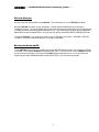
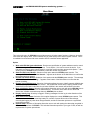
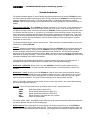
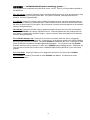
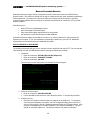
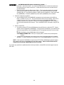
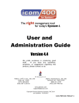
UPS/400
Installation and Administration
Guide
TABLE OF CONTENTS
INTRODUCTION …………………………………………………………………
INSTALLATION/REINSTALLATION INSTRUCTIONS …………………………
GETTING STARTED …………………………………………………………….
RESTARTING AFTER AN IPL …………………………………………………..
MAIN MENU …………………………………………………………………….
SYSTEM ATTRIBUTES …………………………………………………………
SYSTEM ATTRIBUTES (TEST MODE) ………………………………………..
AN EXAMPLE …………………………………………………………………..
REMOTE SYSTEM MAINTENANCE (NETWORKING) ……………………….
UPS/400 NETWORK SUPPORT ……………………………………………..
WORK WITH MONITOR STATUS ……………………………………………..
DISPLAY ACTIVITY LOG ………………………………………………………
WORK WITH CURRENT STATUS ……………………………………………..
SYSTEM SETUP ………………………………………………………………..
TO MAKE UPS/400 PERMANENT ………………………………………….
PRODUCT WARRANTY AND SUPPORT ………………………………………
REMOTE CUSTOMER SUPPORT ………………………………………………
We pride ourselves in producing good stuff. If you have
any questions, problems, or suggestions regarding this
product, please contact us at:
Pinnacle Business Systems
810 S Cincinnati, Suite 200
Tulsa, OK 74119
(877) 369-6922
FAX: (918) 587-1536
www.pbsnow.com
E-mail: [email protected]
PAGE
INTRO
1
2
2
3
5
8
10
12
13
14
20
21
23
24
25
26
UPS/400
. . . an IBM AS/400 UPS power monitoring system . . .
INTRODUCTION
UPS/400 is power monitoring software that continuously monitors your UPS hardware, 24 hours a day, 7
days a week, for alerts indicating an AS/400 system power fluctuation or loss. Upon detecting a notification,
UPS/400 sends messages to users advising them of pending power outage. If power is not returned,
UPS/400 notifies users to sign off the system, takes control of your system, and begins an orderly
shutdown. If at any time during the shutdown period power is restored, UPS/400 resets the system to
normal and informs all users.
User-friendly menus and pop-up windows provide an easy, non-technical approach to installation and
customization. UPS/400 is delivered with a sample shutdown plan already in place, so you can activate the
product with or without further tailoring.
UPS/400 includes a simulated UPS power failure test function that utilizes the shutdown criteria shown on
the System Attributes display. The test function permits you to test your system attributes (whether
defaulted or customized) in simulation mode. UPS/400 executes the specified parameters for each step,
and sends messages to the system operator and active users at each of the six time intervals that you
specify. In this way, you can test and modify the message intervals and message notifications prior to
activating the actual UPS/400.
You can customize UPS/400 to your environment so that messages are sent at up to six intervals that you
specify. UPS/400 also ends active processes and subsystems according to your present instructions.
Field-sensitive help information is provided to assist you in understanding and customizing UPS/400.
In the event of a power loss, system shutdown activities will occur in four basic stages.
STAGED SHUTDOWN PROCEDURES
Once installed and customized, UPS/400 will interact with the system administrator and online users to
effect an orderly shutdown if a UPS power loss occurs. Actions will be taken in the following stages:
Stage 1: Alert
•
•
The system operator is notified that power has been lost and UPS/400 has taken control.
Users are alerted that they are on UPS power and asked to complete critical tasks before possible
signoff.
Stage 2: Preliminary Shutdown
•
•
•
•
•
Continued periodic notifications of shutdown severity status are sent to the system operator
Specified Job Queues are held
Users are notified to end tasks and log off due to continued outage
Specified subsystems are being ended in anticipation of continued power outage
User specified procedures (optional) are run at indicated time intervals
Stage 3: Critical Shutdown
•
•
•
•
System operator is notified that full system shutdown has been initiated
All remaining subsystems are ended
All active users are logged off
A full system AS/400 power down is performed
2
UPS/400
. . . an IBM AS/400 UPS power monitoring system . . .
Stage 4: System Restore and Follow-up Monitoring
•
•
If power is returned, all active users are notified and the system is fully restored to its original active
state.
Remaining battery power is monitored by the system administrator through a UPS current status
display which visually depicts remaining battery life by means of a “battery life line.”
These stages should not be confused with the six staged intervals used during actual UPS/400 shutdown
processing.
USER-CONTROLLED SHUTDOWN PROCEDURES AND MESSAGES
You may define UPS/400 shutdown procedures using the System Attributes display. This display is used to
specify the actions to be taken at the six intervals, including Job Queues to be held, Sub-Systems to end,
and the severity level of the message to be issued. A complete description of this display and its options
are shown on the following pages.
The current UPS Status display can be used to monitor remaining battery life during and after shutdown
procedure. The following page shows a flowchart of UPS/400 shutdown activities.
TECHNICAL SUPPORT
For direct technical support on UPS/400 call … (918) 587-1500
Faxes may be sent to …………………………… (918) 587-1536
Modem dial-in for PTF’s and Updates ………… (918) 587-6923
3
UPS/400
. . . an IBM AS/400 UPS power monitoring system . . .
INSTALLATION/REINSTALLATION INSTRUCTIONS
If you are installing UPS/400 for the first time or reinstalling, the instructions are the same. The program will
install the product for you. If you are re-installing UPS/400, the installation program will create a library
(UPSMBKU) where it will back up the library UPS400 before it begins installation. At the end of a
successful installation, you can delete the library UPSMBKU. If you are using UPS/400 with multiple
AS/400s in an APPN network environment, you must load a copy of UPS/400 on each machine that is to be
monitored in the network.
Sign on as QSECOFR and load the distribution media or follow instructions below for internet download.
First Installation — CD
1. Load CD into the CD-ROM drive
2. Enter the following command: LODRUN DEV(*OPT)
3. The CD-ROM product installation menu is displayed. To install UPS/400, please enter a
1 beside UPS/400.
4. The product information will automatically be installed.
5. Use the command STRUPS400 to access the UPS/400 Main Menu.
First Installation — Tape
1. Load tape in the appropriate drive
2. At the command line type: RSTLIB SAVLIB(MBAINST) DEV(device name)
3. Execute the install command:
MBAINST/MBAINST PRODUCT(UPS) ACTION(*INSTALL) DEV(device name)
4. Use the command GO ICM to access the ICOM/400 Main Menu.
Upgrade
1. Back-up your current UPS/400 system (library UPS400).
2. Follow steps for the proper media format above.
3. NOTE: If you are upgrading to a new system, you will need to restore the old product
library on the new system before proceeding with step 1.
4
UPS/400
. . . an IBM AS/400 UPS power monitoring system . . .
Internet Download Installation
1. At the AS/400 command prompt, type: CRTLIB UPSTRIAL, then: CRTSAVF
UPSTRIAL/UPSTRIAL
2. Go to the Pinnacle website at http://www.pbsnow.com, go to “Products.” Go to
“UPS/400” and click on “Download your 30-day free trial” at the bottom of the page.
You will be asked to register before download. Follow the instructions for download.
3. After downloading, open a DOS session on the PC and at the prompt type: cd/[name
of directory where you downloaded the
4. Then type: FTP [name of your AS/400 or its TCP/IP address]
5. Type your AS/400 user profile and press enter. Type your password and press Enter.
6. Type: bin
7. Type: put UPSTRIAL.SAV UPSTRIAL/UPSTRIAL.SAVF
8. Type: quit and press enter, then: exit and press enter
9. Back at the AS/400 command prompt, type:
RSTOBJ OBJ(*ALL) SAVLIB(UPSTRIAL) DEV(*SAVF) SAVF(UPSTRIAL/UPSTRIAL)
10. You should receive a message indicating that five objects were restored.
Note: You may see a security message. Don’t be alarmed.
11. Type: CALL UPSTRIAL/UPSINST
12. To start UPS/400, type STRUPS400 or GO UPSMON on a command line.
You will be presented with the option to specify UPS/400 Autostart features at this time. A prompt will
be displayed, asking if you wish to use the UPS/400 Autostart Job:
“___ Install the UPS/400 modified System Startup Program (Y/N).”
A response of Y will change the system value QSTRUPPGM to point to Program QSTRUP in UPS400.
This will allow UPS/400 to restart after IPLs. A response of N will cause no changes to be made to the
IBM supplied startup program. You may elect to use the UPS/400 Autostart Job at any time by pressing
F10 while on the UPS/400 System Attributes screen or you can include the supplied source code
(UPS400/UPSSRC member QSTRUP) in your own start-up program.
NOTE: UPS/400 program fixes can be applied by the customer through Automated Customer Support
(ACS) which has been supplied to you on your UPS/400 installation media. This feature permits online
scanning and downloading of appropriate PTFs by the user through access to PBS’s host AS/400. See the
Remote Customer Support section at the back of this manual for instruction on how to install and use this
feature.
5
UPS/400
. . . an IBM AS/400 UPS power monitoring system . . .
GETTING STARTED
Use the command STRUPS400 to start UPS/400. This will transfer you to the UPS/400 Main Menu.
Because UPS/400 runs within its own subsystem, a userid named UPS400 was set up during the
installation process. The userid UPS400 will own the UPS monitoring process and will have a password set
to *NONE to assure protection against unauthorized user. This userid has an authority level comparable to
QSECOFR but cannot be QSECOFR. To review this user profile, enter DSPUSRPRF USRPRF(UPS400).
To execute UPS/400, a user must (a) be within one of the following user classes: *SECADM, *SECOFR,
*SYSOFR, or (b) have a special authority of *ALLJOB or *SECADM.
RESTARTING AFTER AN IPL
To use UPS/400 startup program, the IBM system value QSTRUPPGM should be set to Program QSTRUP
in UPS400. This will allow UPS/400 to restart itself after IPLs. You may elect to use the UPS/400 Autostart
Job at any time by pressing F10 while on the UPS/400 System Attributes screen or you can include the
supplied source code (UPS400/UPSSRC member QSTRUP) in your own start-up program.
6
UPS/400
. . . an IBM AS/400 UPS power monitoring system . . .
MAIN MENU
This is the main menu for UPS/400 that provides access to all other system functions. However, where the
user knows the display name, a menu transfer can be made directly to the desired system function. HELP
is available from all screens and cursor sensitive HELP is available where applicable.
Option
1. Work with UPS/400 System Attributes: Permits user specification of system attributes used to control
UPS/400 during the UPS monitoring process. To use Option 1, the monitor cannot be active. If you
find that the monitor is active, select Option 3 to end the monitor and then proceed with Option 1. After
working with the UPS/400 System Attributes, restart the monitor using Option 2.
2. Start the UPS Power Monitor: Selection of this option starts the UPS/400 power monitor. The
message “UPS/400 Power Monitor Started…” appears at the bottom of the Main Menu to confirm that
the monitor has been started.
3. End the UPS Power Monitor: Selection of this option ends the UPS/400 power monitor. The message
“UPS/400 Power Monitor Ending…” appears at the bottom of the Main Menu to confirm that the
monitor is ending.
4. Remote System Maintenance: Selection of this option allows the user to identify network AS/400s that
will be notified by the UPS/400 power monitor. The AS/400 that serves as the notifying AS/400 for the
network will not be listed in this table, but all other AS/400s in the network will be listed in the table.
5. Work with Monitor Status: Selection of this option allows the user to work with active UPS/400 jobs as
well as review the overall status of the AS/400 activity. This screen is the same as the “Work with
Active Jobs” AS/400 command except that only UPS/400 jobs are listed.
6. Display Activity Log: All activity is logged. Clearing messages from the log is at the discretion of the
user.
7. Work with Current Status: Selection of this option displays the current UPS/400 system status. This
includes information such as remaining battery life, number of power failures since last recharge,
chronological logging of power down step processed, and other information pertinent to a systematic
power down process.
8. System Setup: Selection of this option allows the user to work with setting the values that are global in
nature to the operations of UPS/400. This includes information specific to your type of UPS, as well as
requirements for system power down.
7
UPS/400
. . . an IBM AS/400 UPS power monitoring system . . .
SYSTEM ATTRIBUTES
The System Attributes display is used to identify the system parameters to be used by UPS/400 to create
an orderly system shutdown during a power loss. During a trial period of UPS/400, the date the trial copy
expires is displayed on the screen. This trial expiration date is 30 days after the date you installed
UPS/400. After the system has been purchased and the copy made permanent, this information does not
display.
Test mode for UPS/400: When UPS/400 is installed, the system is in Test mode. This is indicated by the
flashing “*** Test mode ***” at the bottom right hand corner of the screen. Test mode allows the user to
completely simulate a power loss as well as review the UPS/400 monitoring process that would take place if
a real power loss had occurred. If you wish to run a simulation of the monitoring process, notify all users
prior to the test as messages would be sent to their terminals, notifying them of a power loss. Test mode
utilizes all intervals and notification specified in the System Attributes screen, but does not shut down any
processes or execute user Exit Procedures. See the System Attributes (Test mode) page for a further
explanation of this function.
The System Attributes screen contains default values. These should be reviewed/modified by the user as
follows prior to starting UPS/400.
Interval: Intervals are expressed in minutes and are the times that UPS/400 will check system status and
perform specified functions. At each interval, UPS/400 will notify the system operator and/or users with
severity messages, begin specific processes and execute exit procedures. Six intervals are provided,
although the user may use less than this number. Note: Intervals are used in calculation estimated power
down times for severity messages. The first interval can be 0, which means that UPS/400 will issues its first
message immediately upon power loss detection.
Intervals will be automatically adjusted when the remaining battery life is less than the last interval. A
message will be sent to the system operator message queue of the adjusted percentage.
Notification - QSYSOPR: Specify (Y/N) if you wish UPS/400 to notify the system operator during a
specified interval. Normally, the system operator would be notified (Y) at all times during a power loss
situation.
Notification – Users: Specify is you wish UPS/400 to notify all active users during a specified interval.
Notification of users is handled by severity messages ranging from level 1 (least severe) to level 3 (most
severe – see Test mode for severity message text). If you do not wish to notify active users at a given
interval, leave the field blank. The same severity message can be used at several intervals.
While in Test mode, messages will not actually be sent to users, but entries in the Current Status display
will show as though they were sent.
Process: One or two processes may be specified at each interval. Valid processes are:
*JOBQ
*SBS1
*SBS2
*INT
*PWRD
Hold all specified job queues (F6).
End all specified subsystems in SBS1 (F7).
End all specified subsystems in SBS2 (F8).
End all interactive users that are on the system.
Power the system down.
Processes *JOBQ, *SBS1, and *SBS2 are specified via pop-up windows describes below and illustrated in
the System Attribute example on the following page.
Exit Procedure: The exit procedure is used to specify user written programs that you wish UPS/400 to
execute as part of the orderly power down process. These programs must complete processing within the
duration of the current interval and the last interval. If processing does not complete in that time span, the
8
UPS/400
. . . an IBM AS/400 UPS power monitoring system . . .
user program will be ended when the power down occurs. NOTE: There is no exit procedure specified at
the last interval
F6 = Job Queues: Pressing F6 provides a pop-up window that allows the entry of job queues that you wish
UPS/400 to hold during the orderly power down. If the power is restored, these jobs queues will be
released. Format is Program/Library.
F7 = SBS #1: Pressing F7 provides a pop-up window that allows the entry of a list of subsystems that you
wish UPS/400 to end during a specified format. These subsystems will be ended first and should be those
that have the least impact on your system. When the power is restored, these subsystems will be restarted.
Format is Subsystem/Library.
F8 = SBS #2: Pressing F8 provides a pop-up window that allows the entry of a second list of subsystems
that you wish UPS/400 to end during a specified interval. These subsystems have the greatest impact on
your system (i.e. batch and/or interactive usage). If power is restored, these subsystems will be restarted.
Format is Subsystem/Library.
F10 = UPS/400 Autostart Job: Pressing F10 (not shown on screen) allows the user to (Y/N) decide
whether to use the UPS/400 Autostart Job. A response of Y will change the system value QSTRUPPGM to
point to program QSTRUP in UPS400. This allows UPS/400 to restart itself after IPLs. A response of N will
cause no changes to be made to the IBM supplied startup program. You may elect to use the UPS/400
Autostart Job at any time by pressing F10 while on the UPS/400 System Attributes screen. Additionally, the
user may elect to include source code found in UPS400/UPSSRC member QSTRUP in your own startup
program.
F19 = Test mode: Pressing F19 allows you to toggle back and forth in the Test mode for UPS/400.
F23 = Read Me: Pressing F23 provides an online UPS/400 User Manual. F24 will print the online
UPS/400 User manual.
9
UPS/400
. . . an IBM AS/400 UPS power monitoring system . . .
SYSTEM ATTRIBUTES SCREEN
10
UPS/400
. . . an IBM AS/400 UPS power monitoring system . . .
SYSTEM ATTRIBUTES (TEST MODE)
Test mode of UPS/400 is turned on or off from the UPS/400 System Attributes display by pressing F19 (not
shown on the screen). Test mode should not be started until all entries have been made in the System
Attributes screen. After turning Test mode on the user should exit to the Main Menu and Start the UPS
Power Monitor (Option 2). Several items should be noted before proceeding with a test:
1. While in Test mode the AS/400 will not be powered down, nor will job queues be held,
subsystems ended, user messages and user procedures executed. Message delivery to the
system operator and/or users will take place at intervals specified in the System Attributes
screen.
2. When the monitor is started, the message will indicate Test mode.
Two commands allow the simulation of a power loss and restoration without actually disconnecting power or
having to restore it. They are SIMPWRLOSS (simulate power loss) and SIMPWRRST (simulate power
restore). To begin the Test mode process, start the UPS monitor (Main Menu Option 2), then type
SIMPWRLOSS on the UPS/400 Main Menu command line. UPS/400 will now begin simulating a power
loss and sending messages to the system operator and/or users at the specified intervals. The
SIMPWRRST command may be used at any time to end the test. If you let the test run to completion, a
message will be issued to QSYSOPR that the system would have been powered down, but that UPS/400
was in Test mode.
UPS/400 should be further tested by actually disconnecting power to the AS/400. This testing should only
be done after thoroughly testing your UPS hardware. We strongly recommend that testing be performed
when the machine is not in use and when skilled systems/technical personnel are available.
Standard UPS/400 severity level 1, 2, and 3 messages are available, as well as the power restoration
message. Severity codes for messages 1 through 3 can be used on the System Attributes display to
specify which message is to be sent at each interval.
Severity 1:
“Attention – The AS/400 has lost power and is running on battery backup. Be ready
to sign off if the condition is not corrected. Estimated battery life is 25 minutes.”
Severity 2:
“Warning – The AS/400 has lost power and continues to run on battery backup.
Please complete your processing as soon as possible to avoid data lost. Estimated
battery life is 15 minutes.”
Severity 3:
“*** Emergency *** – Due to continued power loss on the AS/400 you are required to
immediately sign off. Estimated battery life is 5 minutes.”
Power
Restore:
“ATTENTION: POWER RESTORED! The AS/400 has just been switched back to
regular service. System will ‘NOT’ be powered down.”
11
UPS/400
. . . an IBM AS/400 UPS power monitoring system . . .
SYSTEM ATTRIBUTES SCREEN (TEST MODE)
12
UPS/400
. . . an IBM AS/400 UPS power monitoring system . . .
AN EXAMPLE
The following narrative describes an example of the functions performed by UPS/400 during a power loss.
The functions performed are based on the system default values carried in the System Attributes screen.
The system administrator has a UPS system for the AS/400 with a recharge time of 120 minutes. The
administrator has determined that the orderly shutdown process should take 25 minutes, broken up into 5,
five-minute intervals with immediate notification of the system operator upon detection of power loss.
Interval 1:
The system operator is notified immediately that a power loss has been detected. Active
users are likewise notified immediately with a severity level 1 message: “Attention – The
AS/400 has lost power and is running on battery backup. Be ready to sign off if the
condition is not corrected. Estimated battery life is 25 minutes.” UPS/400 performs
the process *JOBQ which holds QBATCH. A user program has been specified
(USEREXIT) that begins during interval 1.
Interval 2:
After 5 minutes the system operator is notified with a severity level 2 message: “Warning –
The AS/400 has lost power and continues to run on battery backup. Please complete
your processing as soon as possible to avoid data lost. Estimated battery life is 20
minutes.” Users are not notified at this interval nor are any process or user exits specified.
Interval 3:
After 10 minutes the system operator is notified with another severity level 2 message:
“Warning – The AS/400 has lost power and continues to run on battery backup.
Please complete your processing as soon as possible to avoid data lost. Estimated
battery life is 15 minutes.” Users are sent the same severity level 2 message as the
system operator. The process *SBS1 begins ending subsystems QSNADS and QSPL.
Interval 4:
After 15 minutes the system operator is notified with another severity level 2 message:
“Warning – The AS/400 has lost power and continues to run on battery backup.
Please complete your processing as soon as possible to avoid data lost. Estimated
battery life is 10 minutes.” Users are sent the same severity level 2 message as the
system operator. The process *INT begins, ending interactive users one at a time.
Interval 5:
After 20 minutes the system operator and users are notified with a severity level 3
message: “*** Emergency *** – Due to continued power loss on the AS/400 you are
required to immediately sign off. Estimated battery life is 5 minutes.” The process
*SBS2 begins ending subsystems QBATCH, QINTER, and QCMN.
Interval 6:
After 25 minutes UPS/400 will notify the system operator that the AS/400 is being powered
down and then power down the system.
If during the UPS/400 orderly shutdown, power had been restored the message would have been sent to
the system operator and active users: “ATTENTION: POWER RESTORED! The AS/400 has just been
switched back to regular service. System will ‘NOT’ be powered down.”
This example can be simulated in Test mode, or can be modified to specify your specific UPS shutdown
requirements, and then tested.
13
UPS/400
. . . an IBM AS/400 UPS power monitoring system . . .
SYSTEM ATTRIBUTES SCREEN
(EXAMPLE – SYSTEM DEFAULTS)
These values will be used where not modified by the system operator.
14
UPS/400
. . . an IBM AS/400 UPS power monitoring system . . .
REMOTE SYSTEMS MAINTENANCE (NETWORKING)
The Remote Systems Maintenance screen allows the user to identify remote network AS/400s that will be
notified by UPS/400 in case of a power failure and subsequent power restoration. Any AS/400 in the
network may serve as the notifying AS/400 with all others identified as remote systems. UPS/400 will
manage an orderly system and power shutdown on the notifying machine as well as each of the remote
AS/400s. Note that a copy of UPS/400 must be loaded on each machine that is to be monitored in the
network (see chart on the following page).
Option
1 = Create: Permits the user to identify each remote system name and short description of the remote
system.
4 = Delete: Permits the user to delete entries from the list of remote systems.
9 = Change Text: Permits the user to change the description of the remote system.
15
UPS/400
. . . an IBM AS/400 UPS power monitoring system . . .
UPS/400 NETWORK SUPPORT
Note:
The sensor cable from the UPS may be connected to an AS/400 on the network. All AS/400s to be
networked should be connected to the same power source. The AS/400 with the sensor cable is
the “notifying system,” however any system detecting failure or restore of utility power will notify
ALL systems in its Remote Systems Notification Table (i.e. System A table would contain B, C, and
D; System B table would contain A, C, and D, etc.). If the “notifying system” is disabled for any
reason, the power sensor cable should be reconnected to an active machine. Network capabilities
of UPS/400 depend upon the existence of an AS/400 APPN defined network. Multiple power
sensor cables can be used.
16
UPS/400
. . . an IBM AS/400 UPS power monitoring system . . .
WORK WITH MONITOR STATUS
The Work with Active Jobs display shows the performance and status information for jobs that are currently
active on the system. All information is gathered on a job basis. The jobs are ordered on the basis of the
subsystem in which they are running. Jobs that run in a subsystem (autostart jobs, interactive jobs, batch
jobs, readers and writer) are alphabetized by job name and indented under the subsystem monitor field they
are associated with. Subsystem monitors (with the jobs in the subsystem grouped under each monitor job)
are alphabetized and presented before system (SYS) jobs. The system jobs (SCPF, QSYSARB, QLUS)
are alphabetized by job name and presented following the subsystem monitors and jobs within the
subsystems.
It is possible for a job to not appear on the WRKACTJOB display even though an active status is shown for
the job on one of the following displays:
•
•
•
•
Work with Job (WRKJOB)
Work with Subsystem Job (WRKSBSJOB)
Work with Submitted Jobs (WRKSBMJOB)
Work with User Jobs (WRKUSRJOB)
This is because a status indicator that is used to determine whether a job is active in the job’s internal
structure indicates an active status just before and just after the actual processing of the job. Normally, the
amount of time that a job is in this state is very short, but the following conditions can make it longer:
•
•
If there are many jobs in the system competing for processor use, each job has a smaller share
of processor time, which can increase the amount of time a job is in this state.
The machine does not start the process for the job until an activity level is available for the job
being started. If the activity level has already been reached, the job remains in this state until
an activity level is available.
17
UPS/400
•
. . . an IBM AS/400 UPS power monitoring system . . .
The subsystem can be interrupted while the job is in this state by other requests such as a user
signing on. The job remains in this state until the subsystem has finished processing all of
these requests.
CPU%: This shows the average of processing unit time used by the system during the elapsed time. This
percentage compares to the ratio of the total amount of processing unit time used during the elapsed time
to the total elapsed time. The value in this field is normally higher than the sum of the processing unit time
percentages used by the active jobs displayed because it includes processing unit time used by system
overhead, excluded job, and jobs that have ended during the measurement time interval. This field is zero
when the elapsed time is zero. If there are multiple processors on the system, this field contains the
average processing unit time of the processors.
ELAPSED TIME: This shows the amount of time that has elapsed between the measurement starting time
and the current system time. This field is present in hours, minutes, seconds. This field is zero when the
display is initially requested, or when the display is restarted by pressing the F10 key. The current system
time (end of elapsed interval) is displayed beneath the system name.
ACTIVE JOBS: This shows the current number of jobs active in the system (jobs that have been started,
but have not yet ended), including both user and system jobs.
Options
2 = Change: Use this option to run the Change Job (CHGJOB) command. If no value is specified on the
parameter’s input field, default parameters are shown when you press the F4 key. However,
when values have been specified on the parameter’s input field, the command is run without
the prompt appearing when you press the Enter key. Similarly, when you press the F4 key,
the specified values are highlighted, and defaults are shown for remaining parameters. This
option is not valid for system or subsystem monitor jobs. CHG replaces the status field if the
command runs successfully.
3 = Hold:
Use this option to run the Hold Job (HLDJOB) command; the job’s spooled files are not held
unless the default for the Hold Spooled Files (SPLFILE) parameter is overridden by using the
Parameter’s input field. Select the Hold Reader (HLDRDR) command if this option is selected
for a spooling reader job, or the Hold Writer (HLDWTR) command if this option is selected for
a spooling writer job. This option is not valid for system or subsystem monitor jobs. HLD
replaces the status field if the command was run successfully.
4 = End:
Use this option to run the End Job (ENDJOB) command; the job’s spooled files are not deleted
unless the default for the Deleted Spooled File (SPLFILE) parameter is overridden by using
the parameter’s input field. Unless the OPTION parameter is overridden by the parameter’s
input field, a controlled end is performed as if the End Job (ENDJOB) command was typed
with all the default parameter values assumed. The End Reader (ENDRDR) or End Writer
(ENDWTR) command (with OPTION(*CNTRLD)) is issued if this option is selected for
spooling reader or spooling writer job. This option is not valid for system or subsystem
monitor jobs. END replaces the status field if the command was run successfully.
5 = Work with: Use this option to run the Work with Job (WRKJOB) command, which displays the Work
with Job Menu. The Work with Job Menu allows you to select options to work with:
The possible options are:
• Job status attributes
• Job definition attributes
• Job run attributes
• Job spooled files
• Job log information
• Job program stack information
• Job locks
• Library list information
18
UPS/400
•
•
•
•
. . . an IBM AS/400 UPS power monitoring system . . .
Open file information
File override information
Commitment control status
Communications status information
In addition, the Work with Job Menu allows you to select options to change, hold, release, or end
the job. The Work with Reader (WRKRDR) or Work with Writer (WRKWTR) command is issued if
this option is selected for a spooling reader or spooling writer job.
6 = Release:
Use this option to run the Release Job (RLSJOB) command which releases the job if it is
in the held condition. The Release Reader (RLSRDR) or Release Writer (RLSWTR)
command (with OPTION(*CURRENT)) is run if this option is selected for a spooling reader
or spooling writer job. This option is not valid for system or subsystem monitor jobs. RLS
replaces the status field if the command was run successfully.
7 = Display message: Use this option to display the message for which the job is waiting.
8 = Work with spooled files: Use this option to display the job’s spooled output files.
9 = Exclude:
Use this option to exclude the job from the display. The option has no effect on the job; it
only affects the display.
10 = Display program stack: Use this option to display the job’s program stack
11 = Work with locks: Use this option to work with the job’s locks
13 = Disconnect: Use this option to run the Disconnect Job (DSCJOB) command. All jobs at the device
will be disconnected.
SUBSYSTEM/JOB: This shows the name of the job as identified to the system. Jobs that run in a
subsystem (autostart jobs, interactive jobs, batch jobs, reader, and writers) are indented two positions under
the subsystem monitor job they are associated with. The indentation shows the jobs that are contained in a
subsystem. Subsystem monitors and system jobs are not indented. If the job type is multiple requester
terminal (MRT), the job name is the MRT procedure name.
A plus (+) sign next to the first character of the job name indicates that the job is an active job of a group.
Suspended group jobs (GRP shows as the prefix in the Function column) are excluded from the display
unless the F14 key is pressed. Pressing the F14 key again will cause the suspended group jobs to be
excluded once again. When suspended group jobs are shown, the plus sign is not displayed.
USER: The user name identifies the user who submits the job and the user profile under which the job is
run. If the job type is multiple requester terminal (MRT), the user name is the user that initially started the
MRT job. The user name is the same as the user profile name and can come from several different
sources, depending on the type of job:
•
•
•
Batch job: The user name is specified on the Submit Job (SMBJOB) command, or it is
specified in the job description referred to by the JOB or SBMJOB commands.
Interactive job: The user name is typed in at sign-on, or the user name is provided from the
default in the job description referred to by the work station’s job entry.
Autostart job: The user name is specified in the job description referred to by the job entry for
the autostart job
TYPE: This shows the type of active job. Possible values are:
•
•
•
ASJ: Autostart
BCH: Batch
BCI: Batch immediate
19
UPS/400
•
•
•
•
•
•
•
•
•
. . . an IBM AS/400 UPS power monitoring system . . .
EVK: Started by a procedure start request
INT: Interactive
MRT: Multiple request terminal
PJ: Prestart job
PDJ: Print driver job
RDR: Reader
SBS: Subsystem monitor
SYS: System
WTR: Writer
ELAPSED CPU%: The percent of processing unit time attributes to this job over the elapsed time
compared to the measurement time interval.
FUNCTION: The high-level function being performed by the job. This field is blank when a logged function
has not been performed. The prefix of this field indicates what the characters that follow the hyphen
represent:
•
•
•
•
•
•
•
•
•
•
•
•
•
•
•
•
•
•
CMD: The command is run interactively, or in a batch input stream, or requested from a
system menu. Commands in the CL programs are not logged.
DLY: This job is processing a DLYJOB (Delay Job) command. The time displayed is the
number of seconds that job is delayed (up to 999999 seconds), or the time when the job is to
resume processing (hh:mm:ss), depending on how the command was specified.
GRP: The group name of a suspended group job is displayed.
I/O: The job is a subsystem monitor that is performing input/output operations (I/O) to a
workstation for the sign-on display file. The name displayed is the name of the work station
device.
MNU: The name of the menu
MRT: This is a multiple requester terminal (MRT) job if the type is MRT, or an interactive job
attached to a MRT job is the type is INT. If it is an MRT job, the characters that follow the dash
is a number, a slash (/), and another number. The first number indicates how may requesters
are currently attached to the MRT job, and the second number indicates the maximum number
(MRTMAX) of requesters. NEP indicates the MRT is a “Never-ending-program” (the MRT stays
active even if there are no requester of the MRT). If it is an interactive job attached to a MRT,
the MRT procedure name follows the dash.
PGM: The program name is the high-level program called interactively, or a program called in
a batch input stream, or the initial program specified in the user profile, or the name of a system
request processor. If the high-level program transfers control, the program name remains in
the function field even though it is no longer in the program stack.
PRC: This is the name of the procedure.
IDX: The value is the name of the file associated with an index (access path) rebuild operation.
The previously logged value replaces this value when the index rebuild operation has finished.
LOG-QHST: History information is being logged to a database file.
* - JOBLOG: A job log is being produced
* - DUMP: A dump is in process.
* - ADDLACTJOB: Auxiliary storage is being allocated for the number of active jobs
* - PASSTHRU: The job is a pass-through job.
* - RCLSPLSTG: Empty spooled database members are being deleted specified in the
QADLACTJ system value. This may indicate that the system value for the initial number of
active jobs was set too low.
* - ADLTOTJOB: Auxiliary storage is being allocated for the number of jobs specified in the
QADTOTJ system value
*-CMDENT: The command entry display is being used
* - DLTSPLF: A spooled file is being deleted.
STATUS: The status of the job. Only one status is displayed per job. A blank status field represents a job
that is in transition. The possible values are:
20
UPS/400
•
•
•
•
•
•
•
•
•
•
•
•
•
•
•
•
•
•
•
•
•
•
•
•
•
•
•
•
•
•
•
•
•
•
•
. . . an IBM AS/400 UPS power monitoring system . . .
BSCW: The job is waiting for the completion of an I/O operation to a binary synchronous
device.
CMNA: The job is waiting for the completion of an I/O operation to a communications device in
the activity level.
CMNW: The job is waiting for the completion of an I/O operation to a communications device.
CMTW: The job is waiting for the completion of save-while-active checkpoint processing in
another job. This wait is necessary to prevent a partial commitment control transaction from
being saved to the media.
CPCW: The job is waiting for the completion of a CPI Communications call.
DEQA: The job is waiting for completion of a dequeue operation in the pool activity level.
DEQW: The job is waiting for completion of a dequeue operation. For example, QSYSARB and
subsystem monitors generally wait for work by waiting for a dequeue operation.
DKTA: The job is waiting for the completion of an I/O operation to a diskette device in the
activity level.
DKTW: The job is waiting for the completion of an I/O operation to a diskette device.
DLYW: Due to the Delay Job (DLYJOB) command, the job is delayed waiting for a time interval
to end, or for a specific delay end time. The function field shows either the number of seconds
the job is to delay (999999), or the specific time when the job is to resume running.
DSC: The job has been disconnected from a work station display.
DSPA: The job is waiting for input from a work station display in the activity level.
DSPW: The job is waiting for input from a work station display.
END: The job has been ended with the *IMMED option, or delay time has ended with the
*CNTRLD option.
EOFA: The job is waiting in the activity level to try a read operation again on a database file
after the end-of-file has been reached.
EOFW: The job is waiting to try a read operation again on a database file after the end-of-file
has been reached.
EOJ: The job is ending for a reason other than End Job (ENDJOB) or End Subsystem
(ENDSBS). For example, SIGNOFF, End Group Job (ENDGRPJOB), or an exception that is
not being handled.
EVTW: The job is waiting for an event. For example, QLUS and SCPF generally wait for work
by waiting for an event.
GRP: The job is suspended due to a Transfer to Group Job (TFRGRPJOB) command.
HLD: The job is being held.
ICFA: The job is waiting, in an activity level, for the completion of an I/O operation to an
intersystem communications function file.
ICFW: The job is waiting for the completion of an I/O operation to an intersystem
communications function file.
INEL: The job is ineligible and not currently in the pool activity level.
LCKW: The job is waiting for a lock.
MLTA: The job is waiting, in an activity level, for the completion of an I/O operation to multiple
files.
MLTW: The job is waiting for the completion of an I/O operation to multiple files.
MSGW: The job is waiting for a message from a message queue.
MTXW: The job is in a mutex wait. A mutex is a synchronization function that is used to allow
multiple jobs or processes to serialize their access to shared data.
MXDW: The job is waiting for the completion of an I/O operation to a mixed device file. Details
are in the Remote Work Station Support book.
OPTW: The job is waiting for the completion of an I/O operation to an optical device.
OSIW: The job is waiting for the completion of an OSI Communications Subsystem/400
OSLISN, OSRACS, OSRACA, OSRCV, or OSRCVA operation.
PRTA: The job is waiting for output to a printer to complete in the activity level.
PRTW: The job is waiting for output to a printer to be completed.
PSRW: The job is a prestart job waiting for a program start request.
RUN: The job is currently running in the activity level.
21
UPS/400
•
•
•
•
•
•
•
•
. . . an IBM AS/400 UPS power monitoring system . . .
SELW: This job is in a select wait. More information on the select() function is in the Sockets
APIs chapter in the System API Reference, SC41-4801.
SRQ: The job is the suspended half of a system request job pair.
SVFA: The job is waiting for completion of a Save File operation in the activity level.
SVFW: The job is waiting for completion of a Save File operation.
TAPA: The job is waiting for completion of an I/O operation to a tape device in the activity level.
TAPW: The job is waiting for completion of an I/O operation to a tape device.
TIMA: The job is waiting, in the activity level, for a time interval to end.
TIMW: The job is waiting for a time interval to end.
DISPLAY ACTIVITY LOG
Display Messages
System: PBSEO4
Program . . . . . . :*DSPMSG
Library . . . . . . :
Delivery . . . . . . : *HOLD
Queue . . . . . . . : UPSLOG
Library . . . . .: UPS400
Severity . . . . . . : 00
Type reply (if required), press Enter.
ATTENTION: POWER RESTORED The AS/400 has been switched back to utility power at
09/27/98 20:29:29.
UPS/400 detected a temporary power loss at 09/27/98 20:30:58.
UPS/400 detected a power loss at 20:52. Estimated time to power down is 20 minutes.
ATTENTION: POWER RESTORED The AS/400 has been switched back to utility power at
09/27/98 20:53:45.
UPS/400 detected power loss at 20:54. Estimated time to power down is 19 minutes.
The Display Messages display shows messages sent to a message queue. Among the parameters shown
are message queue name, delivery mode, and break handling program.
For specific information about messages, put the cursor on the message you want information about and
press the Help key. An additional message information display will then be shown.
QUEUE: The name of the message queue that is being shown.
LIBRARY: The name of the library that contains the message queue being shown.
SEVERITY: A two digit value ranging from 00 through 99. The higher the value, the more severe or
important the condition. The value is used when the delivery mode is *BREAK or *NOTIFY. Only
messages equal to or greater than the value defined here will cause the break or notification of the
message to occur.
PROGRAM: The following values may be shown:
•
•
*DSPMSG: When a message arrives for an interactive job with break delivery, the message is
displayed.
A program name: The name of the program that is called when a message arrives if the
message queue is in *BREAK delivery and the message is equal to or greater than the severity
value shown on the display.
LIBRARY: The name of the library that contains the break message handling program.
22
UPS/400
. . . an IBM AS/400 UPS power monitoring system . . .
DELIVERY: The following values may be shown:
•
•
•
•
*BREAK: The job to which the message queue is allocated is interrupted when a message
arrives, and the program or action specified in the Program parameter is performed.
*DFT: Messages requiring replies are answered with their default reply. No messages are
added to the message queue whether they require a reply or not.
*HOLD: The messages are held in the message queue until they are requested by the user or
program.
*NOTIFY: For an interactive job, the audible alarm at the workstation is sounded and the
message-waiting light is turned on.
WORK WITH CURRENT STATUS
You can reach this display by pressing Option 7 (Work with Current Status) on the Main Menu. This screen
displays the current UPS/400 system status. This includes information such as remaining battery life,
number of power failures since last recharge, chronological logging of power down steps processes, as well
as other information pertinent to a systematic power down process.
The following is a description of UPS/400 statistics:
•
•
•
•
UPS/400 subsystem: Active or Inactive status of ZZUPS400, UPS/400 subsystem
Last power fail date: Date of last logged power outage
Last power fail time: Time of last logged power outage
Number of failures: Number of logged power outages since last full recharge of UPS batteries
The following is a description of UPS Battery Statistics:
•
•
Current power source: Source of electrical power currently servicing system. May either by
UPS or Utility
Total battery life: Total minutes of usable battery life as defined in the System Setup screen
23
UPS/400
•
•
. . . an IBM AS/400 UPS power monitoring system . . .
Recharge rate: Rate of recharge as defined in the System Setup screen. This value is
expressed as the number of minutes recharging time required to yield one minute of usable
UPS battery time
Minutes remaining: Number of minutes remaining that the UPS can sustain the system during
a power outage. This value will equal total battery life (above) when the UPS batteries are fully
charged
PERCENTAGE OF UPS BATTERY LIFE REMAINING: This value is graphically indicated as a horizontal
number-line bar and represents the percentage of actual UPS battery time remaining in relation to the total
UPS battery life.
The following is a description of logged UPS/400 activity:
•
•
•
•
Elap: Elapsed number of minutes since FIRST power outage (i.e., since UPS was fully
charged.)
Act Time: Actual time of event
Status: Status of event. TEST indicates event occurred during UPS/400 Test mode. ACTIVE
indicates event has completed. Note that ACTIVE and DONE will not be reported in Test mode
Description: Textual description of occurrence. An asterisk (*) indicates a group process that
occurred as a scheduled event in the UPS/400 System Attributes screen
NOTE: You can now access a command line window from the current UPS Status Screen by pressing the
F9 key and then Option 7. This will provide you with greater mobility within the system.
24
UPS/400
. . . an IBM AS/400 UPS power monitoring system . . .
SYSTEM SETUP
This menu allows setting of values that are global in nature to the operations of UPS/400. This includes
information specific to your type of UPS, as well as requirements for system power down. For this section,
you will need to acquire some of this information from you UPS documentation or your supplier.
UPS BATTERY SPECIFICATIONS:
•
•
Battery life: The number of minutes your UPS can sustain your system in the event of a power
outage
Recharge rate: The number of minutes recharging time required to yield one minute of usable
UPS battery time
ALTERNATIVE SUBSYSTEM SPECIFICATIONS:
•
•
•
Subsystem description: Valid AS/400 object name you wish to assign to alternative
subsystems
Library: Library name where UPS/400 will create the alternate subsystem description
Work stations 1 – 5: Work station name entries assigned to alternate subsystems
Note: This portion of the System Setup (Alternative Subsystem Specifications) is optional. The alternate
subsystem defined here will be automatically started immediately after all other interactive subsystems are
ended in the power down process (i.e., *INT step you scheduled in the System Attributes menu). The
library names above should already exit, but the subsystem description will be created by UPS/400.
25
UPS/400
. . . an IBM AS/400 UPS power monitoring system . . .
TO MAKE UPS/400 PERMANENT
To make UPS/400 permanent, the user should complete and return the AS/Manager License agreement to
PBS. Based on your CPU serial number(s), PBS product support will issue a permanent security
number(s). To install this permanent security number, please do the following:
1. Start UPS/400 by keying in STRUPS400 and press Enter.
2. Key in UPDUPSSYSV on the command line and press Enter.
3. Input the 7 digit permanent security number supplied by PBS product support in the entry field
and press Enter. The user will get a message indicating that the product has been made
permanent.
If questions arise during this process, call PBS product support at (918) 587-1500.
26
UPS/400
. . . an IBM AS/400 UPS power monitoring system . . .
PRODUCT WARRANTY AND SUPPORT
This section contains important warranty and product support information. Please read it carefully.
PRODUCT SUPPORT:
UPS/400 has been thoroughly tested and comes with online help text as well as user documentation.
Displays are simple to understand and use. However, if you have any problems using UPS/400, we
recommend the following steps:
1. Review the documentation and help text provided by UPS/400, which contains answers to a
majority of questions that might arise.
2. Have job logs, error messages (first and second levels), screen prints, etc. available to discuss
with an PBS technical support representative
3. Call an PBS product support representative at the number show at the front of this manual.
PHONE SUPPORT:
Call PBS technical support between the hours of 7:30 a.m. and 5:30 p.m. CST five days a week for
questions or problems you may be having. We will be happy to answer them. If the problem is of a critical
nature, our 24-hour answering service can reach us at all hours.
Please have ready any material pertaining to your questions (job logs/printouts to refer to, displays, etc.).
This makes it easier for our product support analyst to understand the problem and assist you promptly.
PRODUCT WARRANTY AND MAINTENANCE:
PBS warrants that UPS/400 software will be free of defects for 90-days after software installation. Product
technical phone support and replacement materials will be provided during this period at no charge.
Annual maintenance agreements may be purchased at published rates by licensed users for ongoing
UPS/400 support after the initial 90-day free warranty period. Payment of this fee entitles you to continuing
technical support, product enhancements, problem corrections, OS/400 release compatibility, and new
releases of UPS/400.
27
UPS/400
. . . an IBM AS/400 UPS power monitoring system . . .
REMOTE CUSTOMER SUPPORT
Automated Customer Support (ACS) is designed to permit remote user access to the PBS customer
support AS/400. This product is offered at no charge to customers who are under a software maintenance
license agreement. It provides menu screens to assist you in defining ACS connectivity to the PBS
customer support machine and in ordering any necessary enhancements or corrections (PTFs) to PBS
software products.
ACS allows you to:
•
•
•
•
Order PTFs for any AS/Manager product
Send a message to technical support
Page a technical support representative for emergencies
Ask questions or search for answers on Q&A database.
Automated Customer Support is provided as a service to our valued customers in order to assure the
highest level of support. If you are interested in purchasing the product for your own PTF distribution
requirements, call us and we will provide additional information.
INSTALL/REINSTALL PROCEDURE:
The following instructions will give you an overview of how to load ACS and order a PTF. Be sure that the
user installing ACS has *ALLOBJ authority before entering the following commands.
1. Install ACS:
• Enter the command: RSTLIB LIB(ACSLIBC) DEV(xxxxx)
• Enter the command: ADDLIBLE ACSLIBC
• Enter the command: GO ASM
This will take you to the main menu for Automated Customer Support.
2. Check the resource name:
• Enter the command: DSPLIND QESLINE
• Look at the IBM line and check the value “Resource Name.” It will normally be LIN011.
3. Configure the line:
• Use option 2 (Configure Communication for Support) on the ACS menu. To access the
online user documentation, take Option 3 for the Configuration Menu, then press F23 to
view it or F24 to print it. Option 3 should be executed before any PTFs are ordered. It will
create a line (ASM$LINE), a controller (ASM$CTL) and a device (ASM$DEV). The user
should not vary these objects on. The order process will vary them on during the
28
UPS/400
. . . an IBM AS/400 UPS power monitoring system . . .
procedure – and off at the end. You must insure that there are no other lines varied onto
the resource that you name for this line. In most cases the screen can be used with the
provided defaults.
• Enter the resource name if different from LIN011. The line speed should be left at 2400
and the phone number should be correct unless you do not have a direct line and need
something like “9:” to precede the number in order to get an outside line. Press enter and a
line (ASM$LINE), a controller (ASM$CTL) and a device (ASM$DEV) will be created.
4. Check for another line varied on:
• Use the WRKCFGSTS *LIN ASM$LINE command to look at the status of the ACS line.
Enter a 1 beside it to vary it on. The line should then show connect pending. Now enter a
2 beside it to vary it off. If you get a failure on the vary on, then there is another line
currently varied on to the resource. Enter the command WRKHDWRSC TYPE (*CMN) to
look at all lines that share this resource. Then use WRKCFGSTS command to vary the line
off.
5. Order or view PTFs:
• Use option 1 (Order PTFs from AS/Manager) on the ACS menu to order the PTF. Simply
enter the PTF ID supplied by AS/Manager. The PTF will be transferred to you machine and
will be accompanied by a report highlighting the PTF and giving instruction on how to load
it.
PTF ID: Provided to you by AS/Manager technical support
CUSTOMER INFORMATION: Enter you company name, contact name, and telephone
number.
• A message will be displayed at the bottom of the screen giving the status of the transfer
operation. To view a summary of all available PTFs, enter ASMSUMMARY in the PTF ID.
NOTE: If the keyword *PASSTHRU is keyed into the PTF ID field, AS/Manager technical support
will be able to sign onto your AS/400 to provide online support. Please contact PBS technical
support before entering *PASSTHRU into the PTF ID field.
If you have any questions or problems with the above procedure, contact PBS. technical support at (918)
587-1500.
29