1
SPARC Enterprise M3000 Server
Service Manual
Part No.: E26435-01
Manual Code: C120-E540-06EN
March 2012
Copyright © 2008, 2012, Fujitsu Limited. All rights reserved.
Oracle and/or its affiliates provided technical input and review on portions of this material.
Oracle and/or its affiliates and Fujitsu Limited each own or control intellectual property rights relating to products and technology described in this
document, and such products, technology and this document are protected by copyright laws, patents, and other intellectual property laws and
international treaties.
This document and the product and technology to which it pertains are distributed under licenses restricting their use, copying, distribution, and
decompilation. No part of such product or technology, or of this document, may be reproduced in any form by any means without prior written
authorization of Oracle and/or its affiliates and Fujitsu Limited, and their applicable licensors, if any. The furnishings of this document to you does not
give you any rights or licenses, express or implied, with respect to the product or technology to which it pertains, and this document does not contain or
represent any commitment of any kind on the part of Oracle or Fujitsu Limited, or any affiliate of either of them.
This document and the product and technology described in this document may incorporate third-party intellectual property copyrighted by and/or
licensed from the suppliers to Oracle and/or its affiliates and Fujitsu Limited, including software and font technology.
Per the terms of the GPL or LGPL, a copy of the source code governed by the GPL or LGPL, as applicable, is available upon request by the End User. Please
contact Oracle and/or its affiliates or Fujitsu Limited.
This distribution may include materials developed by third parties.
Parts of the product may be derived from Berkeley BSD systems, licensed from the University of California. UNIX is a registered trademark in the U.S. and
in other countries, exclusively licensed through X/Open Company, Ltd.
Oracle and Java are registered trademarks of Oracle and/or its affiliates. Fujitsu and the Fujitsu logo are registered trademarks of Fujitsu Limited.
All SPARC trademarks are used under license and are registered trademarks of SPARC International, Inc. in the U.S. and other countries. Products bearing
SPARC trademarks are based upon architectures developed by Oracle and/or its affiliates. SPARC64 is a trademark of SPARC International, Inc., used
under license by Fujitsu Microelectronics, Inc. and Fujitsu Limited. Other names may be trademarks of their respective owners.
United States Government Rights - Commercial use. U.S. Government users are subject to the standard government user license agreements of Oracle
and/or its affiliates and Fujitsu Limited and the applicable provisions of the FAR and its supplements.
Disclaimer: The only warranties granted by Oracle and Fujitsu Limited, and/or any affiliate of either of them in connection with this document or any
product or technology described herein are those expressly set forth in the license agreement pursuant to which the product or technology is provided.
EXCEPT AS EXPRESSLY SET FORTH IN SUCH AGREEMENT, ORACLE OR FUJITSU LIMITED, AND/OR THEIR AFFILIATES MAKE NO
REPRESENTATIONS OR WARRANTIES OF ANY KIND (EXPRESS OR IMPLIED) REGARDING SUCH PRODUCT OR TECHNOLOGY OR THIS
DOCUMENT, WHICH ARE ALL PROVIDED AS IS, AND ALL EXPRESS OR IMPLIED CONDITIONS, REPRESENTATIONS AND WARRANTIES,
INCLUDING WITHOUT LIMITATION ANY IMPLIED WARRANTY OF MERCHANTABILITY, FITNESS FOR A PARTICULAR PURPOSE OR NONINFRINGEMENT, ARE DISCLAIMED, EXCEPT TO THE EXTENT THAT SUCH DISCLAIMERS ARE HELD TO BE LEGALLY INVALID. Unless
otherwise expressly set forth in such agreement, to the extent allowed by applicable law, in no event shall Oracle or Fujitsu Limited, and/or any of their
affiliates have any liability to any third party under any legal theory for any loss of revenues or profits, loss of use or data, or business interruptions, or for
any indirect, special, incidental or consequential damages, even if advised of the possibility of such damages.
DOCUMENTATION IS PROVIDED “AS IS” AND ALL EXPRESS OR IMPLIED CONDITIONS, REPRESENTATIONS AND WARRANTIES,
INCLUDING ANY IMPLIED WARRANTY OF MERCHANTABILITY, FITNESS FOR A PARTICULAR PURPOSE OR NON-INFRINGEMENT, ARE
DISCLAIMED, EXCEPT TO THE EXTENT THAT SUCH DISCLAIMERS ARE HELD TO BE LEGALLY INVALID.
Please
Recycle
Copyright © 2008, 2012, Fujitsu Limited. Tous droits réservés.
Oracle et/ou ses sociétés affiliées ont fourni et vérifié des données techniques de certaines parties de ce composant.
Oracle et/ou ses sociétés affiliées et Fujitsu Limited détiennent et contrôlent chacune des droits de propriété intellectuelle relatifs aux produits et
technologies décrits dans ce document. De même, ces produits, technologies et ce document sont protégés par des lois sur le copyright, des brevets,
d’autres lois sur la propriété intellectuelle et des traités internationaux.
Ce document, le produit et les technologies afférents sont exclusivement distribués avec des licences qui en restreignent l’utilisation, la copie, la
distribution et la décompilation. Aucune partie de ce produit, de ces technologies ou de ce document ne peut être reproduite sous quelque forme que ce
soit, par quelque moyen que ce soit, sans l’autorisation écrite préalable d’Oracle et/ou ses sociétés affiliées et de Fujitsu Limited, et de leurs éventuels
bailleurs de licence. Ce document, bien qu’il vous ait été fourni, ne vous confère aucun droit et aucune licence, expresses ou tacites, concernant le produit
ou la technologie auxquels il se rapporte. Par ailleurs, il ne contient ni ne représente aucun engagement, de quelque type que ce soit, de la part d’Oracle ou
de Fujitsu Limited, ou des sociétés affiliées de l’une ou l’autre entité.
Ce document, ainsi que les produits et technologies qu’il décrit, peuvent inclure des droits de propriété intellectuelle de parties tierces protégés par
copyright et/ou cédés sous licence par des fournisseurs à Oracle et/ou ses sociétés affiliées et Fujitsu Limited, y compris des logiciels et des technologies
relatives aux polices de caractères.
Conformément aux conditions de la licence GPL ou LGPL, une copie du code source régi par la licence GPL ou LGPL, selon le cas, est disponible sur
demande par l’Utilisateur final. Veuillez contacter Oracle et/ou ses sociétés affiliées ou Fujitsu Limited.
Cette distribution peut comprendre des composants développés par des parties tierces.
Des parties de ce produit peuvent être dérivées des systèmes Berkeley BSD, distribués sous licence par l’Université de Californie. UNIX est une marque
déposée aux États-Unis et dans d’autres pays, distribuée exclusivement sous licence par X/Open Company, Ltd.
Oracle et Java sont des marques déposées d’Oracle Corporation et/ou de ses sociétés affiliées. Fujitsu et le logo Fujitsu sont des marques déposées de
Fujitsu Limited.
Toutes les marques SPARC sont utilisées sous licence et sont des marques déposées de SPARC International, Inc., aux États-Unis et dans d’autres pays. Les
produits portant la marque SPARC reposent sur des architectures développées par Oracle et/ou ses sociétés affiliées. SPARC64 est une marque de SPARC
International, Inc., utilisée sous licence par Fujitsu Microelectronics, Inc. et Fujitsu Limited. Tout autre nom mentionné peut correspondre à des marques
appartenant à d’autres propriétaires.
United States Government Rights - Commercial use. U.S. Government users are subject to the standard government user license agreements of Oracle
and/or its affiliates and Fujitsu Limited and the applicable provisions of the FAR and its supplements.
Avis de non-responsabilité : les seules garanties octroyées par Oracle et Fujitsu Limited et/ou toute société affiliée de l’une ou l’autre entité en rapport avec
ce document ou tout produit ou toute technologie décrits dans les présentes correspondent aux garanties expressément stipulées dans le contrat de licence
régissant le produit ou la technologie fournis. SAUF MENTION CONTRAIRE EXPRESSÉMENT STIPULÉE DANS CE CONTRAT, ORACLE OU FUJITSU
LIMITED ET LES SOCIÉTÉS AFFILIÉES À L’UNE OU L’AUTRE ENTITÉ REJETTENT TOUTE REPRÉSENTATION OU TOUTE GARANTIE, QUELLE
QU’EN SOIT LA NATURE (EXPRESSE OU IMPLICITE) CONCERNANT CE PRODUIT, CETTE TECHNOLOGIE OU CE DOCUMENT, LESQUELS
SONT FOURNIS EN L’ÉTAT. EN OUTRE, TOUTES LES CONDITIONS, REPRÉSENTATIONS ET GARANTIES EXPRESSES OU TACITES, Y COMPRIS
NOTAMMENT TOUTE GARANTIE IMPLICITE RELATIVE À LA QUALITÉ MARCHANDE, À L’APTITUDE À UNE UTILISATION PARTICULIÈRE
OU À L’ABSENCE DE CONTREFAÇON, SONT EXCLUES, DANS LA MESURE AUTORISÉE PAR LA LOI APPLICABLE. Sauf mention contraire
expressément stipulée dans ce contrat, dans la mesure autorisée par la loi applicable, en aucun cas Oracle ou Fujitsu Limited et/ou l’une ou l’autre de leurs
sociétés affiliées ne sauraient être tenues responsables envers une quelconque partie tierce, sous quelque théorie juridique que ce soit, de tout manque à
gagner ou de perte de profit, de problèmes d’utilisation ou de perte de données, ou d’interruptions d’activités, ou de tout dommage indirect, spécial,
secondaire ou consécutif, même si ces entités ont été préalablement informées d’une telle éventualité.
LA DOCUMENTATION EST FOURNIE « EN L’ÉTAT » ET TOUTE AUTRE CONDITION, DÉCLARATION ET GARANTIE, EXPRESSE OU TACITE, EST
FORMELLEMENT EXCLUE, DANS LA MESURE AUTORISÉE PAR LA LOI EN VIGUEUR, Y COMPRIS NOTAMMENT TOUTE GARANTIE
IMPLICITE RELATIVE À LA QUALITÉ MARCHANDE, À L’APTITUDE À UNE UTILISATION PARTICULIÈRE OU À L’ABSENCE DE
CONTREFAÇON.
Contents
Preface
1.
2.
3.
xiii
Safety Precautions for Maintenance
1.1
ESD Precautions
1.2
Server Precautions
1–1
1–1
1–3
1.2.1
Electrical Safety Precautions
1.2.2
Equipment Rack Safety Precautions
1.2.3
Component Handling Precautions
Hardware Overview
1–3
1–4
2–1
2.1
Name of Each Part
2.2
Operator Panel
2–1
2–5
2.2.1
Operator Panel Overview
2–6
2.2.2
Switches on the Operator Panel
2.2.3
LEDs on the Operator Panel
2.3
LED Functions of Components
2.4
External Interface Port on Rear Panel
2.5
Labels
2–7
2–9
2–11
2–13
2–17
Troubleshooting
3.1
1–3
3–1
Emergency Power Off
3–1
v
3.2
Failure Diagnostic Method
3.3
Checking the Server and System Configuration
3.3.1
3.4
3.5
3.3.2.1
Checking the Software Configuration
3.3.2.2
Checking the Firmware Configuration
3.3.2.3
Downloading Error Log Information
Predictive Self-Healing Tools
3.4.2
Monitoring Output
3.4.3
Messaging Output
vi
3–11
3.5.2
Using the showlogs Command
3.5.3
Using the showstatus Command
3.5.4
Using the fmdump Command
3–11
3–14
3–15
3–16
3.5.4.1
fmdump -V Command
3–16
3.5.4.2
fmdump -e Command
3–17
Using the fmadm Command
3–17
3.5.5.1
Using the fmadm faulty Command
3.5.5.2
fmadm repair Command
3–18
3.5.5.3
fmadm config Command
3–18
Using the fmstat Command
3–19
General Oracle Solaris Troubleshooting Commands
3.6.2
3–7
3–10
Using the showhardconf Command
Using the iostat Command
3.6.1.1
3–7
3–8
3.5.1
3.6.1
3–7
3–10
Using Troubleshooting Commands
Options
3–20
3–20
Using the prtdiag Command
SPARC Enterprise M3000 Server Service Manual • March 2012
3–21
3–19
3–4
3–5
3–8
3.4.1
3.5.6
3.6
Checking the Hardware Configuration.
Checking the Software and Firmware Configurations
Error Conditions
3.5.5
3–4
Checking the Hardware Configuration and FRU Status
3.3.1.1
3.3.2
3–2
3–17
3–6
3.6.2.1
3.6.3
Options
Options
Options
FRU Replacement Preparation
3–26
3–26
3–27
3–27
3–28
3–29
Using the prstat Command
3.6.7.1
4.
Options
Using the ps Command
3.6.6.1
3.6.7
3–24
Using the ping Command
3.6.5.1
3.6.6
Options
3–23
Using the netstat Command
3.6.4.1
3.6.5
3–21
Using the prtconf Command
3.6.3.1
3.6.4
Options
3–29
3–30
4–1
4.1
Tools Required for Maintenance
4.2
FRU Replacement and Installation Methods
4.3
4.4
4.5
4.2.1
FRU Replacement
4.2.2
FRU Installation
4–1
4–2
4–2
4–4
Active Replacement/Active Addition
4–5
4.3.1
Releasing a FRU from a Domain
4–5
4.3.2
FRU Removal and Replacement
4–6
4.3.3
Configuring a FRU in a Domain
4–6
4.3.4
Verifying the Hardware Operation
Hot Replacement/Hot Addition
4–7
4–7
4.4.1
FRU Removal and Replacement (Power supply unit/Fan unit)
4–8
4.4.2
Verifying the Hardware Operation (Power supply unit/Fan unit)
4–10
4.4.3
Verifying the Hardware Operation (Hard disk drive)
Cold Replacement/Cold Addition
4.5.1
Powering off the Server
4–11
4–12
4–12
Contents
vii
5.2
5.3
5.4
7.
Power off by Using the Operator Panel
FRU Removal and Replacement
4.5.3
Powering on the Server
4–12
4–13
4–13
4–13
4.5.3.1
Power-on by Using the XSCF Command
4.5.3.2
Power-on by Using the Operator Panel
Verifying the Hardware Operation
4–13
4–14
4–15
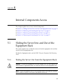
5–1
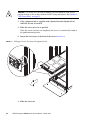
Sliding the Server Into and Out of the Equipment Rack
5.1.1
Sliding the Server Out from the Equipment Rack
5.1.2
Sliding the Server into the Equipment Rack
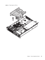
Removing and Attaching the Top Cover
5.2.1
Removing the Top Cover
5–3
5.2.2
Attaching the Top Cover
5–4
Removing and Attaching the Air Duct
5.3.1
Removing the Air Duct
5–4
5.3.2
Attaching the Air Duct
5–6
5–3
5–4
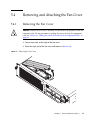
Removing and Attaching the Fan Cover
5.4.1
Removing the Fan Cover
5–7
5.4.2
Attaching the Fan Cover
5–8
Motherboard Unit Replacement
6–1
6.1
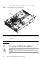
Accessing the Motherboard Unit
6–4
6.2
Removing the Motherboard Unit
6–7
6.3
Mounting the Motherboard Unit
6–8
6.4
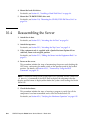
Reassembling the Server
6–9
Replacement and Installation of Memory
7.1
viii
4.5.1.2
Internal Components Access
5.1
6.
Power-off by Using the XSCF Command
4.5.2
4.5.4
5.
4.5.1.1
Memory Mounting Rules
7–3
SPARC Enterprise M3000 Server Service Manual • March 2012
7–1
5–7
5–3
5–1
5–1
8.
9.
Confirmation of DIMM Information
7.1.2
Memory Mounting Conditions
7.2
Accessing the DIMMs
7–7
7.3
Removing the DIMMs
7–8
7.4
Installing the DIMMs
7.5
Reassembling the Server
7–3
7–4
7–9
7–9
Replacement and Installation of PCIe Cards
8.1
Accessing a PCIe Card
8–3
8.2
Removing a PCIe Card
8–4
8.3
Mounting a PCIe Card
8–5
8.4
Reassembling the Server
8–1
8–5
Replacement and Installation of a Hard Disk Drive (HDD)
9.1
10.
7.1.1
Accessing a Hard Disk Drive
9.1.1
Active Replacement
9.1.2
Hot Replacement
9.1.3
Cold Replacement
9–1
9–3
9–3
9–3
9–4
9.2
Removing a Hard Disk Drive
9.3
Installing a Hard Disk Drive
9.4
Reassembling the Server
9–4
9–6
9–6
9.4.1
Active Replacement
9.4.2
Hot Replacement
9.4.3
Cold Replacement
9–6
9–7
9–7
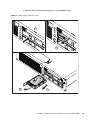
Replacing the Hard Disk Drive Backplane
10–1
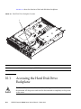
10.1
Accessing the Hard Disk Drive Backplane
10–2
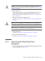
10.2
Removing the Hard Disk Drive Backplane
10–3
10.3
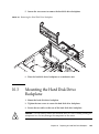
Mounting the Hard Disk Drive Backplane
10–5
10.4
Reassembling the Server
10–6
Contents
ix
11.
12.
13.
14.
15.
x
CD-RW/DVD-RW Drive Unit (DVDU) Replacement
11–1
11.1
Identifying the Type of CD-RW/DVD-RW Drive Unit
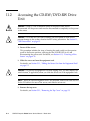
11.2
Accessing the CD-RW/DVD-RW Drive Unit
11–4
11.3
Removing the CD-RW/DVD-RW Drive Unit
11–5
11.4
Mounting the CD-RW/DVD-RW Drive Unit
11–6
11.5
Reassembling the Server
11–6
Power Supply Unit Replacement
12–1
12.1
Accessing a Power Supply Unit
12.2
Removing the Power Supply Unit
12–3
12.3
Mounting the Power Supply Unit
12–5
12.4
Reassembling the Server
Fan Unit Replacement
12–3
12–5
13–1
13.1
Accessing a Fan Unit
13–3
13.2
Removing a Fan Unit
13–4
13.3
Mounting a Fan Unit
13–5
13.4
Reassembling the Server
Fan Backplane Replacement
13–5
14–1
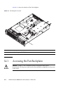
14.1
Accessing the Fan Backplane
14–2
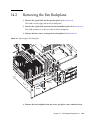
14.2
Removing the Fan Backplane
14–5
14.3
Mounting the Fan Backplane
14–6
14.4
Reassembling the Server
Operator Panel Replacement
14–6
15–1
15.1
Accessing the Operator Panel
15–3
15.2
Removing the Operator Panel
15–4
15.3
Mounting the Operator Panel
15–5
15.4
Reassembling the Server
15–5
SPARC Enterprise M3000 Server Service Manual • March 2012
11–3
A. Components List
B. FRU List
A–1
B–1
B.1
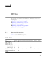
Server Overview
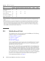
B.2
Motherboard Unit
B.3
B–1
B–2
B.2.1
Memory (DIMM)
B–3
B.2.2
PCIe Slot
B.2.3
CPU
B.2.4
XSCF Unit
Drive
B–5
B.3.1
Hard Disk Drive
B.3.2
CD-RW/DVD-RW Drive Unit (DVDU)
B–3
B–4
B.4
Power Supply Unit
B.5
Fan Unit
B–4
B–5
B–6
B–7
C. External Interface Specifications
C–1
C.1
Serial Port
C.2
UPC Port
C–2
C.3
USB Port
C–3
C.4
SAS Port
C–3
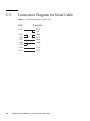
C.5
Connection Diagram for Serial Cable
D. UPS Controller
C–2
Overview
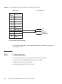
D.2
Signal Cable
D.3
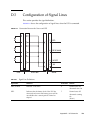
Configuration of Signal Lines
D.4
Power Supply Conditions
D–1
D–2
D.4.1
Input Circuit
D.4.2
Output Circuit
UPS Cable
C–4
D–1
D.1
D.5
B–6
D–3
D–4
D–4
D–5
D–5
Contents
xi
D.6
Connections
D–6
E. DC Power Supply Model
E–1
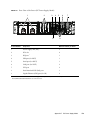
E.1
The Server Views
E–2
E.2
LED Functions of Power Supply Unit
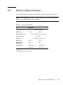
E.3
Electrical Specifications
E.4
Using the showhardconf Command
E–5
F. Reactivating a Hardware RAID Boot Volume
Abbreviations
Index
xii
E–4
Abbreviations–1
Index–1
SPARC Enterprise M3000 Server Service Manual • March 2012
E–6
F–1
Preface
This manual describes how to service SPARC Enterprise M3000 server from Oracle
and Fujitsu. This document is written for maintenance providers who have received
formal service training. References herein to the M3000 server are reference to the
SPARC Enterprise M3000 server.
This preface includes the following sections:
■
“Audience” on page xiii
■
“Related Documentation” on page xiv
■
“Text Conventions” on page xv
■
“Notes on Safety” on page xv
■
“Syntax of the Command-Line Interface (CLI)” on page xvi
■
“Documentation Feedback” on page xvi
Audience
This guide is written for experienced system administrators with working
knowledge of computer networks and advanced knowledge of the Oracle Solaris
Operating System (Oracle Solaris OS).
xiii
Related Documentation
All documents for your server are available online at the following locations.
Documentation
Link
Sun Oracle software-related manuals
(Oracle Solaris OS, and so on)
http://www.oracle.com/documentation
Fujitsu documents
http://www.fujitsu.com/sparcenterprise/manual/
Oracle M-series server documents
http://www.oracle.com/technetwork/documentation/spar
c-mseries-servers-252709.html
The following table lists titles of related documents.
Related SPARC Enterprise M3000 Server Documents
SPARC Enterprise M3000 Server Site Planning Guide
SPARC Enterprise Equipment Rack Mounting Guide
SPARC Enterprise M3000 Server Getting Started Guide*
SPARC Enterprise M3000 Server Overview Guide
SPARC Enterprise M3000/M4000/M5000/M8000/M9000 Servers Important Legal and Safety Information *
SPARC Enterprise M3000 Server Safety and Compliance Guide
SPARC Enterprise M3000 Server Installation Guide
SPARC Enterprise M3000 Server Service Manual
SPARC Enterprise M3000/M4000/M5000/M8000/M9000 Servers Administration Guide
SPARC Enterprise M3000/M4000/M5000/M8000/M9000 Servers XSCF User’s Guide
SPARC Enterprise M3000/M4000/M5000/M8000/M9000 Servers XSCF Reference Manual
SPARC Enterprise M3000/M4000/M5000/M8000/M9000 Servers Product Notes†
SPARC Enterprise M3000 Server Product Notes
SPARC Enterprise M3000/M4000/M5000/M8000/M9000 Servers Glossary
* This is a printed document.
† Beginning with the XCP 1100 release.
xiv
SPARC Enterprise M3000 Server Service Manual • March 2012
Text Conventions
This manual uses the following fonts and symbols to express specific types of
information.
Font/Symbol
Meaning
Example
AaBbCc123
What you type, when contrasted
with on-screen computer output.
This font represents the example of
command input in the frame.
XSCF> adduser jsmith
AaBbCc123
The names of commands, files, and
directories; on-screen computer
output.
This font represents the example of
command output in the frame.
XSCF> showuser -P
User Name:
jsmith
Privileges: useradm
auditadm
Italic
Indicates the name of a reference
manual, a variable, or userreplaceable text.
See the SPARC Enterprise
M3000/M4000/M5000/M8000/M9000
Servers XSCF User’s Guide.
""
Indicates names of chapters,
sections, items, buttons, or menus.
See Chapter 2, "System Features."
Notes on Safety
Read the following documents thoroughly before using or handling any SPARC
Enterprise M3000 server:
■
SPARC Enterprise M3000/M4000/M5000/M8000/M9000 Servers Important Legal and
Safety Information
■
SPARC Enterprise M3000 Server Safety and Compliance Guide
Preface
xv
Syntax of the Command-Line Interface
(CLI)
The command syntax is as follows:
■
A variable that requires input of a value must be put in Italics.
■
An optional element must be enclosed in [].
■
A group of options for an optional keyword must be enclosed in [] and delimited
by |.
Documentation Feedback
If you have any comments or requests regarding this document, go to the following
websites:
■
For Oracle users:
http://www.oracle.com/goto/docfeedback
Include the title and part number of your document with your feedback:
SPARC Enterprise M3000 Server Service Manual, part number E26435-01
■
For Fujitsu users:
http://www.fujitsu.com/global/contact/computing/sparce_index.html
xvi
SPARC Enterprise M3000 Server Service Manual • March 2012
CHAPTER
1
Safety Precautions for Maintenance
This chapter provides safety precautions required for maintenance.
1.1
■
Section 1.1, “ESD Precautions” on page 1-1
■
Section 1.2, “Server Precautions” on page 1-3
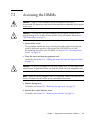
ESD Precautions
To ensure that you and bystanders are not exposed to harm and to prevent damage
to the system, observe the following safety precautions.
TABLE 1-1
ESD Precautions
Item
Precaution
ESD connector/wrist strap
Connect the ESD connector to your server and wear the antistatic wrist strap
when handling printed circuit boards. See FIGURE 1-1, for the wrist strap
connection destination.
Conductive mat
An approved conductive mat provides protection from static damage when
used with a wrist strap. The mat also cushions and protects small parts that
are attached to printed circuit boards.
ESD safe packaging box
Place a printed board or component in the ESD safe packaging box after you
remove it.
1-1
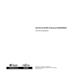
FIGURE 1-1
Wrist Strap Connection Destination
■ FRU* other than hard disk drive and fan unit
Connect to either upper right on the front or upper left
on the rear of the server.
■ Hard disk drive or fan unit:
Connect to one of two thumbscrews
on the front of the server.
* FRU: Field Replaceable Unit
Caution – Do not connect the wrist strap cable to the conductive mat. Connect it
directly to the server.
The wrist strap and FRU must have the same level of potential.
1-2
SPARC Enterprise M3000 Server Service Manual • March 2012
1.2
Server Precautions
When maintaining the server, observe the following precautions for your protection.
■
Follow all cautions, warnings, and instructions marked on the server.
Caution – Do not insert any object in an opening of the server. If any object comes
into contact with a high-voltage part or short-circuits a component, fire or electric
shock might result.
■
1.2.1
Refer servicing of the server to the service engineer.
Electrical Safety Precautions
■
Ensure that the voltage and frequency of the power source to be used matches the
electrical rating labels on the server.
■
Wear antistatic wrist straps when handling hard disk drives, motherboard units,
or other printed circuit boards.
■
Use grounded power outlets as described in the SPARC Enterprise M3000 Server
Installation Guide.
Caution – Do not make mechanical or electrical modifications. We are not
responsible for regulatory compliance of modified servers.
1.2.2
Equipment Rack Safety Precautions
■
The equipment racks must be anchored to the floor, ceiling, or to adjacent frames.
■
Some equipment racks are supplied with a Quake-Resistant Options Kit or
stabilizer, which supports the weight of the server when it is extended on its slide
rails. This prevents the equipment from toppling over during installation or
maintenance.
■
In the following cases, a safety evaluation must be conducted by the service
engineer prior to installation or maintenance work.
■
When no Quake-Resistant Options Kits or stabilizers are attached and the
equipment rack is not anchored to the floor, ensure safety by confirming that
the server does not fall over when it is pulled out from the slide rails.
Chapter 1
Safety Precautions for Maintenance
1-3
■
When the equipment rack is mounted on a raised floor, ensure that the raised
floor has sufficient strength to withstand the weight upon it when the server is
extended on its slide rails. Fix the equipment rack through the raised floor to
the concrete floor below it, using a proprietary mounting kit for this purpose.
Caution – If more than one server is installed in an equipment rack, maintain the
servers one at a time.
For details of equipment racks, see the SPARC Enterprise Equipment Rack Mounting Guide.
1.2.3
Component Handling Precautions
Caution – The server is easily damaged by static electricity. To prevent damage to
printed circuit boards, wear a wrist strap and connect it to the server prior to
starting maintenance.
Caution – Do not bend the motherboard unit (MBU) or the components mounted
on circuit boards might be damaged.
To prevent the motherboard unit from being bent, observe the following precautions:
■
Hold the motherboard unit by the handle, where the board stiffener is located.
■
When removing the motherboard unit from the packaging, keep the motherboard
unit horizontal until you lay it on the cushioned conductive mat.
■
Connectors and components on the motherboard unit have thin pins that bend
easily. Therefore, do not place the motherboard unit on a hard surface.
■
Be careful not to damage the small parts located on both sides of the motherboard unit.
Caution – The heat sinks can be damaged by incorrect handling. Do not touch the
heat sinks while replacing or removing motherboard units. If a heat sink is loose or
broken, obtain a replacement motherboard unit. When storing or carrying a
motherboard unit, ensure that the heat sinks have sufficient protection.
Caution – When removing a cable such as the LAN cable, if your fingers do not
reach the latch lock of the connecter, use a flat head screwdriver to push the latch to
disconnect the cable. If you forcibly insert your fingers into the service clearance, the
LAN port of the motherboard unit of PCI Express (PCIe) cards may be damaged.
1-4
SPARC Enterprise M3000 Server Service Manual • March 2012
CHAPTER
2
Hardware Overview
This chapter explains the names of components and also explains the LEDs on the
operator panel and rear panel.
2.1
■
Section 2.1, “Name of Each Part” on page 2-1
■
Section 2.2, “Operator Panel” on page 2-5
■
Section 2.3, “LED Functions of Components” on page 2-11
■
Section 2.4, “External Interface Port on Rear Panel” on page 2-13
■
Section 2.5, “Labels” on page 2-17
Name of Each Part
This section explains the names of parts mounted on the M3000 server.
Among these parts, those which can be replaced in the field by a certified field
engineer are called Field Replaceable Units (FRU). For information on the actual
replacement/expansion procedure for FRUs, see Chapter 6 to Chapter 15.
The server consists of a chassis in which various components are mounted, top cover
to protect the mounted components, front panel, and rear panel. An operator panel
is located on the front panel, and ports used to connect external interfaces are
located on the rear panel. From the LEDs on the operator panel and rear panel, error
and other status information can be checked. For details, see Section 2.2, “Operator
Panel” on page 2-5 to Section 2.4, “External Interface Port on Rear Panel” on
page 2-13.
2-1
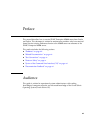
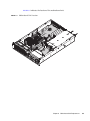
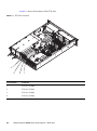
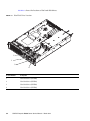
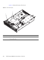
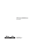
FIGURE 2-1, FIGURE 2-2 and FIGURE 2-3 are the internal view, front view, and rear view
of the server, respectively, and they indicate the names and abbreviated names of
main components.
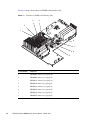
Server (Internal View)
FIGURE 2-1
Fan backplane (FANBP_B) CPU
Memory (DIMM)
XSCF unit (XSCFU)
PCIe
slot
Fan
unit
(FAN_A)
DC-DC
converter
(DDC)
Hard disk drive backplane
(HDDBP)
Motherboard unit
CD-RW/DVD-RW drive unit (DVDU)
Power supply unit (PSU)
PCIe card (PCIe)
Note – The form of the DC-DC converter may be different depending on the
motherboard unit which is mounted.
2-2
SPARC Enterprise M3000 Server Service Manual • March 2012
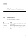
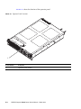
FIGURE 2-2
Server (Front View)
1
2
Location Number
Component
1
Fan unit (FAN_A)
2
Operator panel (OPNL)
3
Hard disk drive (HDD) (2.5-inch SAS disk)
4
CD-RW/DVD-RW drive unit (DVDU)
3
4
Chapter 2
Hardware Overview
2-3
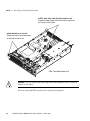
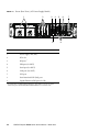
FIGURE 2-3
Server (Rear View) (AC Power Supply Model)
1
2
3
4
8
Location Number
Component
1
Power supply unit (PSU)
2
PCIe slot
3
RCI port *
4
USB port (for XSCF)
5
Serial port (for XSCF)
6
LAN port (for XSCF)
7
UPC port
8
Serial Attached SCSI (SAS) port
9
Gigabit Ethernet (GbE) port (for OS)
* For information on whether the RCI function is supported for your server, see the
SPARC Enterprise M3000/M4000/M5000/M8000/M9000 Servers Product Notes.
2-4
SPARC Enterprise M3000 Server Service Manual • March 2012
5
6
9
7
2.2
Operator Panel
The operator panel has the important function of controlling the power of the server.
The operator panel is usually locked with a key to prevent the server from being
mistakenly powered off during system operation.
Before starting maintenance work, ask the system administrator to unlock the
operator panel.
Chapter 2
Hardware Overview
2-5
2.2.1
Operator Panel Overview
The system administrator or service engineer checks the operating status of the
server with LEDs or operates the power supply with the power switch. FIGURE 2-4
shows the location of the operator panel.
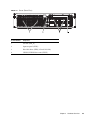
FIGURE 2-4
Operator Panel Location
1
2
3
4
5
2-6
Location Number
Component
1
POWER LED
2
XSCF STANDBY LED
3
CHECK LED
4
Power button
5
Mode switch (key switch)
SPARC Enterprise M3000 Server Service Manual • March 2012
2.2.2
Switches on the Operator Panel
TABLE 2-1 depicts the functions of the switches on the operator panel.
The switches on the operator panel include the mode switch for setting the operation
mode and the power switch for turning on and off the server.
TABLE 2-1
Switch
Switches (Operator Panel)
Name
Description of Function
Mode
Switch
(Key
Switch)
This switch is used to set the operation mode for the server.
Insert the special key that is under the customer's control, to
switch between modes.
Locked
Normal operation mode
• The system can be powered on with the power button, but
it cannot be powered off with the power button.
• The key can be pulled out at this key position.
Service
Mode for maintenance
• The system can be powered on and off with the power
button.
• The key cannot be pulled out at this key position.
• To stop and maintain the server, set the mode to Service.
Power button
This button is used to turn on or turn off the power to the
server (a domain).
Power on and power off are controlled by pressing this button
in different patterns, as described below.
Holding down the button
for a short time
(less than 4 seconds)
Regardless of the mode switch setting, the server is powered
on.
If set in the XSCF, facility (air conditioners) power-on and
warm-up processing is skipped. *
Holding down the button
for a long time in Service
mode
(4 seconds or longer)
• If power to the server is on, OS shutdown processing is
executed for all domains before the system is powered off.
• If the server is being powered on, the power-on processing
is cancelled, and the server is powered off.
• If the server is being powered off, the operation of the
power button is ignored, and the power-off processing is
continued.
* In normal operation, the server is powered on only when the data center environmental conditions satisfy the specified values. Then,
the server remains in the reset state until the operating system is booted.
Chapter 2
Hardware Overview
2-7
TABLE 2-2 shows the function of the mode switch.
TABLE 2-2
Mode Switch Function
Function
Mode Switch
Locked
Service
Inhibition of Break Signal Reception
Enabled Reception of the
Break signal can be
enabled or disabled for
each domain using
setdomainmode
command.
Disabled
Power On/Off by power button
Only Power On is
enabled.
Enabled
2-8
SPARC Enterprise M3000 Server Service Manual • March 2012
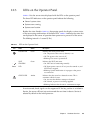
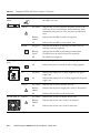
2.2.3
LEDs on the Operator Panel
TABLE 2-3 lists the server states displayed with the LEDs on the operator panel.
The three LED indicators on the operator panel indicate the following:
■
General system status
■
System error warning
■
System error location
Besides the states listed in TABLE 2-3, the operator panel also displays various states
of the server using combinations of the three LEDs. TABLE 2-4 indicates the states that
are displayed in the course of operation from power-on to power-off of the server.
The blinking interval is 1 second (1 Hz).
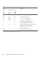
TABLE 2-3
Icon
XSCF
LEDs on the Operator Panel
Name
Status
Description
POWER LED
Green
Indicates the server power status.
• On: The power to the server (a domain) is on.
• Off: The power to the server is off.
• Blinking: The server is powered off.
XSCF
STANDBY
LED
Green
Indicates the XSCF unit status.
• On: XSCF unit is functioning normally.
• Off: Input power source is off or is just after turned on, and
XSCF unit is stopped.
• Blinking: System initialization is in progress after power
was turned on.
CHECK LED
Amber
Indicates that the server has detected an error. This is
sometimes called a locator.
• On: An error that hinders startup was detected.
• Off: Normal, or power is not being supplied.
• Blinking: Indicates that the unit is a maintenance target.
In service mode, break signals can be suppressed. If the key position is switched to
Service, the server will boot into service mode the next time it reboots. Service is
selected by default at the initial power-on.
Chapter 2
Hardware Overview
2-9
TABLE 2-4
State Display by Combination of LEDs on the Operator Panel
Name
POWER *
Description
XSCF STANDBY
CHECK
XSCF
Off
Off
Off
Power is not being supplied.
Off
Off
On
Power has been turned on.
Off
Blinking
Off
The XSCF unit is being initialized.
Off
Blinking
On
An error occurred in the XSCF unit.
Off
On
Off
The XSCF unit is in the standby state.
The server is waiting for power-on of the air
conditioning facilities in the data center.
On
On
Off
Warm-up standby processing is in progress (power is
turned on after the end of processing).
The power-on sequence is in progress.
The server is in operation.
Blinking
On
Off
The power-off sequence is in progress.
(The fan units are stopped after the end of processing.)
* READY LED is referred to when the XSCF unit status is indicated.
2-10
SPARC Enterprise M3000 Server Service Manual • March 2012
2.3
LED Functions of Components
This section explains the LEDs of each component. When replacing a FRU, check in
advance the states of LEDs.
Normal system state can be confirmed by checking the operator panel. If an error
occurs in an individual hardware component in the server, the LEDs of the
component containing the hardware component which caused the error will indicate
the error location. However, some components such as DIMMs do not have LEDs.
To check the state of a component that has no LEDs, use an XSCF Shell command
such as showhardconf in the maintenance terminal. For details, see TABLE 3-1.
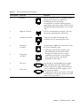
TABLE 2-5 describes the component LEDs and their functions.
TABLE 2-5
Component LEDs and Their Functions
Component
Name
Status
Motherboard unit
(MBU)
POWER
Indicates whether the MBU is operating.
CHECK
Description
On (green)
Indicates that the motherboard is operating. The motherboard
cannot be removed from the server while the POWER LED is
on.
Blinking
(green)
Indicates that the MBU is being incorporated into the system
or being disconnected from the system.
Off
Indicates that the MBU is stopped. The MBU can be
disconnected and replaced.
Indicates the motherboard unit status.
On (amber)
Indicates that an error occurred in the MBU.
Off
Indicates that the MBU is in the normal state.
Chapter 2
Hardware Overview
2-11
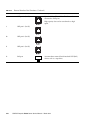
TABLE 2-5
Component LEDs and Their Functions (Continued)
Component
Name
Status
Hard disk drive
(HDD)
Indicates that the hard disk drive can be removed. However,
this LED is not used.
CHECK
READY
OK
Power supply unit
(PSU)
DC
AC
CHECK
Fan unit (FAN_A)
2-12
Description
CHECK
On (amber)
Indicates that an error occurred in the HDD. However, this
LED stays on for several minutes (until initialization starts)
immediately after power-on. This state does not indicate an
error.
Blinking
(amber)
Indicates that the HDD is ready to be replaced.
Off
Indicates that the HDD is in the normal state.
On (green)
Indicates that the HDD is operating. The HDD cannot be
removed (cannot be replaced).
Blinking
(green)
Indicates that the HDD is performing communication.
The HDD cannot be removed (cannot be replaced).
Off
The HDD can be replaced.
On (green)
Indicates that power is turned on and being supplied.
Off
Indicates that power is turned off and not being supplied.
On (green)
Indicates that input power is being supplied to the power
supply unit.
Off
Indicates that input power is not being supplied to the power
supply unit.
On (amber)
Indicates that an error occurred in the PSU.
Blinking
(amber)
Indicates that the power supply unit is ready to be replaced.
Off
Indicates that the PSU is in the normal state.
On (amber)
Indicates that an error occurred in the fan unit.
Blinking
(amber)
Indicates that the fan unit is ready to be replaced.
Off
Indicates that the fan unit is in the normal state.
SPARC Enterprise M3000 Server Service Manual • March 2012
TABLE 2-5
Component LEDs and Their Functions (Continued)
Component
Name
Status
Description
LAN port display
part
ACTIVE
On (green)
Indicates that communication is being performed through the
LAN port.
Off
Indicates that communication is not being performed through
the LAN port.
On (amber)
Indicates that the communication speed of the LAN port is 1
Gbps.
On (green)
Indicates that the communication speed of the LAN port is
100 Mbps.
Off
Indicates that the communication speed of the LAN port is 10
Mbps.
LINK
SPEED
2.4
External Interface Port on Rear Panel
This section shows the location of the external interface ports located on the server
rear panel and explains their functions.
Chapter 2
Hardware Overview
2-13
FIGURE 2-5
External Interface Port Locations
1
2
12
2-14
11
3
4
5
6
10
9
8
7
SPARC Enterprise M3000 Server Service Manual • March 2012
TABLE 2-6
External Interface Port Functions
Location Number
Component
Description
1
RCI port
Used to connect the server to a peripheral device
having a RCI connector to enable power
interlocking and error monitoring.
For information on whether the RCI function is
supported for your server, see the SPARC Enterprise
M3000/M4000/M5000/M8000/M9000 Servers Product
Notes.
2
USB port (for XSCF)
Exclusive for maintenance personnel. Cannot be
connected to general-purpose USB devices.
3
Serial port (for XSCF)
Connects to the XSCF unit through serial
connection to set up and manage the server.
4
LAN port 1
(for XSCF)
5
LAN port 0
(for XSCF)
Accommodates a 100Base-TX LAN cable to set up
the server and display status.
• XSCF Shell (command-line interface: CLI):
• XSCF Web (browser user interface: BUI):
Through CLI or BUI, the user or system
administrator monitors the server, displays
status, operates domains, and displays
information on the console.
6
UPC port 1
7
UPC port 0
By connecting an uninterruptible power supply
(UPS) unit that has the UPS controller (UPC)
interface, stable power supply is provided in the
event of a failure in the power supply or even a
large-scale power failure.
If a single power feed is used, connect a UPS cable
to UPC port 0. In a dual power feed, connect UPS
cables to UPC ports 0 and 1.
Chapter 2
Hardware Overview
2-15
TABLE 2-6
External Interface Port Functions (Continued)
Location Number
Component
Description
8
GbE port 0 (for OS)
Up to 4 100Base-TX/1000Base-T cables can be
connected to GbE ports.
High-capacity data can be transferred at a high
speed.
9
GbE port 1 (for OS)
10
GbE port 2 (for OS)
11
GbE port 3 (for OS)
12
SAS port
2-16
Accommodates external Serial Attached SCSI (SAS)
devices such as a tape drive.
SPARC Enterprise M3000 Server Service Manual • March 2012
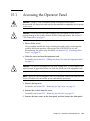
2.5
Labels
This section explains the labels and the card affixed to the server.
Note – The information on the label might differ from that shown on the affixed
labels.
■
The model number, serial number, and hardware version, all of which are
required for maintenance and management, are shown on the system faceplate
label.
■
The standards label is affixed close to the system faceplate label and shows the
approval standards.
■
Safety: NRTL/C
■
Radio wave: VCCI-A, FCC-A, DOC-A, MIC
■
Safety and radio wave: CE
A label-affixed card that can be inserted or extracted is provided near the power
supply unit at the right side at the rear of the server (see TABLE 2-6). The card should
be inserted in such a way that the standards label faces the outside of the server and
the system faceplate label faces the inside of the server.
Chapter 2
Hardware Overview
2-17
FIGURE 2-6
Label Locations
Inside: System faceplate label
Outside: Standards label
2-18
SPARC Enterprise M3000 Server Service Manual • March 2012
CHAPTER
3
Troubleshooting
This chapter provides the fault diagnosis information and the actions to take for
problems.
3.1
■
Section 3.1, “Emergency Power Off” on page 3-1
■
Section 3.2, “Failure Diagnostic Method” on page 3-2
■
Section 3.3, “Checking the Server and System Configuration” on page 3-4
■
Section 3.4, “Error Conditions” on page 3-8
■
Section 3.5, “Using Troubleshooting Commands” on page 3-11
■
Section 3.6, “General Oracle Solaris Troubleshooting Commands” on page 3-19
Emergency Power Off
This section explains how to power off in an emergency.
Caution – In an emergency (such as smoke or flames coming from the server),
immediately stop using the server and turn off the power supply. Regardless of the
type of business, give top priority to fire prevention measures.
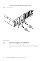
1. Press the power switch for more than 4 seconds to power off the server.
3-1
2. Remove the power cord clamp and disconnect the cable.
FIGURE 3-1
3.2
Power-off Method
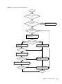
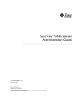
Failure Diagnostic Method
When an error occurs, a message is displayed on the maintenance monitor in many
cases. Use the flowchart in FIGURE 3-2 to find the correct methods for diagnosing
failures.
3-2
SPARC Enterprise M3000 Server Service Manual • March 2012
FIGURE 3-2
Diagnostic Method Flowchart
Start
OS panic or performance
error?
Is the power OK or
AC OK LED off?
YES
Check the power supply unit and
its connection.
NO
The XSCF
mail function sent an E-mail
message?
YES
NO
Check whether an error message
is displayed on the OS console
and XSCF console.
NO
The XSCF console displays
an error message?
Check /var/adm/messages in the
Oracle Solaris OS.
FMA message?
YES
Execute showlogs or fmadm in the
XSCF to display fault information.
NO
YES
Execute fmadm to display fault
information.
Can the message
ID be used?
NO
Make a memo of the displayed
fault information.
YES
Enter the message ID in https://support.oracle.com/
to refer to fault information.
Has the problem been
solved?
NO
Contact your service engineer.
YES
End
Chapter 3
Troubleshooting
3-3
3.3
Checking the Server and System
Configuration
The operating conditions must remain the same before and after maintenance. If an
error occurs in the server, save the system configuration and component status
information. Confirm that the recovered state after maintenance is the same as that
before maintenance.
If an error occurs in the server, one of the following messages is displayed.
3.3.1
■
Oracle Solaris Operating System message file
■
XSCF Shell showhardconf(8) command and showstatus(8) command
■
Management console
■
Service processor log
Checking the Hardware Configuration and FRU
Status
To replace a faulty FRU and perform the maintenance on the server, it is important
to check and understand the hardware configuration of the server and the state of
each hardware component.
The hardware configuration refers to information that indicates to which layer a
hardware component belongs.
The status of each hardware component refers to information on the conditions of a
standard or optional component in the server: temperature, power supply voltage,
CPU operating conditions, and other status information.
To check the hardware configuration and the status of each hardware component,
use XSCF Shell commands from the maintenance terminal. See TABLE 3-1 for the
commands used.
TABLE 3-1
3-4
Commands for Checking Hardware Configuration
Command
Description
showhardconf
Displays hardware configuration.
showstatus
Displays the status of a component. This command is used only when a
faulty component is checked.
SPARC Enterprise M3000 Server Service Manual • March 2012
TABLE 3-1
Commands for Checking Hardware Configuration (Continued)
Command
Description
showboards
Displays information on the system board (XSB).
showdcl
Displays the hardware resource configuration information of a domain.
showfru
Displays the setting information of a device.
The status of each component can be checked based on the On or blinking state of
the component LEDs.
For the component types and LED states, see TABLE 2-3 and TABLE 2-5.
For details of commands, see the SPARC Enterprise
M3000/M4000/M5000/M8000/M9000 Servers XSCF User's Guide and the SPARC
Enterprise M3000/M4000/M5000/M8000/M9000 Servers XSCF Reference Manual.
3.3.1.1
Checking the Hardware Configuration.
To check the hardware configuration, authority (user account) to log in with the
XSCF user account to the XSCF is required. The following procedure can be used to
check the hardware configuration from the maintenance terminal.
Ask the system administrator for the required information, such as the user account
and password. For details, see the SPARC Enterprise
M3000/M4000/M5000/M8000/M9000 Servers XSCF User's Guide.
1. Log in to XSCF Shell.
2. Type showhardconf.
XSCF> showhardconf
The showhardconf command displays hardware configuration information. For
details, see the SPARC Enterprise M3000/M4000/M5000/M8000/M9000 Servers XSCF
User's Guide.
Chapter 3
Troubleshooting
3-5
3.3.2
Checking the Software and Firmware
Configurations
The software and firmware configurations and versions affect the operation of the
server. To change the configuration or investigate a problem, check the latest
information and check for any problems in the software.
Software and firmware varies according to user conditions.
■
The software configuration and version can be checked in the Oracle Solaris
Operating System. Refer to the Oracle Solaris OS documentation for more
information.
■
The firmware configuration and versions can be checked from the maintenance
terminal using XSCF Shell commands. Refer to the SPARC Enterprise
M3000/M4000/M5000/M8000/M9000 Servers XSCF User's Guide for more detailed
information.
Check the software and firmware configuration information with assistance from the
system administrator. However, if you have received login authority from the system
administrator, the following commands can be used from the maintenance terminal
for these checks:
Commands for Checking the Software Configuration
TABLE 3-2
Command
Description
showrev(1M)
Displays system configuration information and Oracle Solaris OS patch information.
uname(1)
Outputs current system information.
Commands for Checking the XSCF Firmware Configuration
TABLE 3-3
Command
Description
version(8)
Outputs current firmware version information.
showhardconf(8)
Outputs information on the components mounted on the server.
showstatus(8)
Displays the status of a component. This command is used only when a faulty
component is checked.
showboards(8)
Displays XSB information. It can display information on an XSB that belongs to the
specified domain and information on all XSBs mounted. An XSB combines hardware
resources on physical system boards. The M3000 server consists of a single physical
system board (Uni-XSB).
showdcl(8)
Displays the configuration information of a domain (hardware resource information).
showfru(8)
Displays the setting information of a device.
3-6
SPARC Enterprise M3000 Server Service Manual • March 2012
3.3.2.1
Checking the Software Configuration
The following procedure can be used to check the software configuration from the
domain console.
●
Type showrev.
# showrev
The showrev command displays system configuration information on the screen.
3.3.2.2
Checking the Firmware Configuration
Login authority is required to check the firmware configuration. The procedure
below can be used to check the configuration from the maintenance terminal.
1. Log in with the account of the XSCF hardware field engineer.
2. Type version.
XSCF> version
The version command displays firmware version information on the screen. For
details, see the SPARC Enterprise M3000/M4000/M5000/M8000/M9000 Servers XSCF
User's Guide.
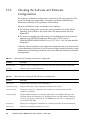
3.3.2.3
Downloading Error Log Information
To download error log information, use the XSCF log fetch function. The XSCF unit
has an interface with external units so that the authorized service personnel can
easily obtain useful maintenance information such as error logs.
Connect the maintenance terminal, and use the XSCF Shell or XSCF Web to
download error log information to the maintenance terminal.
Chapter 3
Troubleshooting
3-7
3.4
Error Conditions
This section describes error conditions and relevant corrective actions.
This work is explained in the following sections:
■
■
■
Section 3.4.1, “Predictive Self-Healing Tools” on page 3-8
Section 3.4.2, “Monitoring Output” on page 3-10
Section 3.4.3, “Messaging Output” on page 3-10
Details of the fault information, see the SPARC Enterprise
M3000/M4000/M5000/M8000/M9000 Servers XSCF User's Guide.
You can find more detailed descriptions of Oracle Solaris OS Predictive Self-Healing
at the website below:
http://www.oracle.com/technetwork/systems/performance/selfheal138059.html
Predictive self-healing is an architecture and methodology for automatically
diagnosing, reporting, and handling software and hardware error conditions. This
new technology reduces the time required to debug a hardware or software problem
and provides the administrator and service engineer with detailed data about each
error.
3.4.1
Predictive Self-Healing Tools
In the Oracle Solaris OS, Oracle Solaris Fault Manager runs in the background. When
an error occurs, the system software recognizes the error and attempts to determine
the faulty hardware component. The system software also takes steps to prevent the
faulty component from being used until it has been replaced. The system software
performs the following activities:
3-8
■
Receives telemetry information about errors detected by the system software.
■
Diagnoses the errors.
■
Initiates predictive self-healing activities. For example, Oracle Solaris Fault
Manager can disable faulty components.
■
When possible, causes the faulty FRU to provide an LED indication of the error in
addition to populating system console messages with more details.
SPARC Enterprise M3000 Server Service Manual • March 2012
TABLE 3-4 shows typical messages generated when an error occurs. Messages are
displayed on your console and are recorded in the /var/adm/messages file.
A message in TABLE 3-4 indicates that the fault has already been diagnosed. If there
was any corrective action that the system could take, the system has already taken it.
If your server is still running, the corrective action continues to be taken.
TABLE 3-4
Predictive Self-Healing Messages
Output Displayed
Description
Nov 1 16:30:20 dt88-292 EVENT-TIME:Tue Nov 1
16:30:20 PST 2005
EVENT-TIME: The time stamp of the diagnosis
Nov 1 16:30:20 dt88-292 PLATFORM:SUNW,A70,
CSN:-, HOSTNAME:dt88-292
PLATFORM: A description of the server encountering
the error
Nov 1 16:30:20 dt88-292 SOURCE:eft, REV: 1.13
SOURCE: Information on the Diagnosis Engine used to
determine the error
Nov 1 16:30:20 dt88-292 EVENT-ID:afc7e660-d6094b2f-86b8-ae7c6b8d50c4
EVENT-ID: The Universally Unique event ID for this
error
Nov 1 16:30:20 dt88-292 DESC:
DESC: A basic description of the error
Nov 1 16:30:20 dt88-292 A problem was detected in the
PCI Express subsystem
Nov 1 16:30:20 dt88-292 Refer to
http://sun.com/msg/SUN4-8000-0Y for more
information.
WEB SITE: Where to find specific information and
actions for this error
Nov 1 16:30:20 dt88-292 AUTO-RESPONSE:One or
more device instances may be disabled.
AUTO-RESPONSE: What, if anything, the system did
to alleviate any follow-on problems
Nov 1 16:30:20 dt88-292 IMPACT:Loss of services
provided by the device instances associated with this
fault.
IMPACT: A description of what is considered to be the
impact of the fault
Nov 1 16:30:20 dt88-292 REC-ACTION:Schedule a
repair procedure to replace the affected device.Use
Nov 1 16:30:20 dt88-292 fmdump -v -u EVENT_ID to
identify the device or contact Sun for support.
REC-ACTION: A brief description of the corrective
action the system administrator should take
Chapter 3
Troubleshooting
3-9
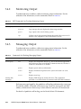
3.4.2
Monitoring Output
To understand error conditions, collect monitoring output information. For the
collection of the information, use the commands shown in TABLE 3-5.
TABLE 3-5
XSCF Commands for Checking Monitoring Output
Command
Operand
Description
showlogs(8)
console
Displays the console of a domain.
monitor
Logs messages that are displayed in the message window.
panic
Logs output to the console during a panic.
ipl
Collects console data generated during the period of the power-on of a
domain to the completion of the Oracle Solaris OS start.
3.4.3
Messaging Output
To understand error conditions, collect messaging output information. For the
collection of the information, use the commands shown in TABLE 3-6.
TABLE 3-6
Commands for Checking Messaging Output
Command
Operand
Description
showlogs(8)
env
Displays the temperature history log. The environmental temperature
data and power status are indicated in 10-minute intervals. The data is
stored for a maximum of six months.
power
Displays power and reset information.
event
Displays information reported to the system and stored it as event
logs.
error
Displays error logs.
fmdump (1M)
fmdump(8)
Displays FMA diagnostic results and errors. This command is
provided as an Oracle Solaris OS command and XSCF Shell command.
Each error message logged by the predictive self-healing architecture has a message
ID and Web address associated with the message. From this message ID and Web
address, information on the most up-to-date corrective measures can be retrieved.
For details of predictive self-healing, see the Oracle Solaris OS documents.
3-10
SPARC Enterprise M3000 Server Service Manual • March 2012
3.5
Using Troubleshooting Commands
When any message listed in TABLE 3-4 is displayed, detailed information on the error
may be required. For details on troubleshooting commands, see manual pages of the
Oracle Solaris OS or XSCF Shell. This section provides detailed explanations of the
following commands:
3.5.1
■
“Using the showhardconf Command” on page 3-11
■
“Using the showlogs Command” on page 3-14
■
“Using the showstatus Command” on page 3-15
■
“Using the fmdump Command” on page 3-16
■
“Using the fmadm Command” on page 3-17
■
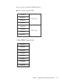
“Using the fmstat Command” on page 3-19
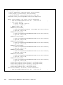
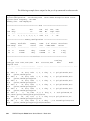
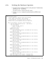
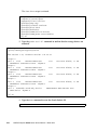
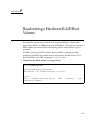
Using the showhardconf Command
The showhardconf command displays information on each FRU. The following
information is displayed:
■
Current configuration and status
■
Number of mounted units
■
Domain information
■
Name properties of the PCIe card
Chapter 3
Troubleshooting
3-11
XSCF> showhardconf
SPARC Enterprise M3000;
+ Serial:IKK0813023; Operator_Panel_Switch:Locked;
+ Power_Supply_System:Single; SCF-ID:XSCF#0;
+ System_Power:On; System_Phase:Cabinet Power On;
Domain#0 Domain_Status:OpenBoot Execution Completed;
MBU_A Status:Normal; Ver:0101h; Serial:PP0829045F ;
+ FRU-Part-Number:CA07082-D902 A1
/541-3302-01
;
+ CPU Status:Normal;
+ Freq:2.520 GHz; Type:32;
+ Core:4; Strand:2;
+ Memory_Size:8 GB;
MEM#0A Status:Normal;
+ Code:ce0000000000000001M3 93T2950EZA-CE6 4145-473b3c23;
+ Type:1A; Size:1 GB;
MEM#0B Status:Normal;
+ Code:7f7ffe00000000004aEBE10RD4AJFA-5C-E 3020-223b2918;
+ Type:1A; Size:1 GB;
MEM#1A Status:Normal;
+ Code:7f7ffe00000000004aEBE10RD4AJFA-5C-E 3020-223b28af;
+ Type:1A; Size:1 GB;
MEM#1B Status:Normal;
+ Code:7f7ffe00000000004aEBE10RD4AJFA-5C-E 3020-223b28ab;
+ Type:1A; Size:1 GB;
MEM#2A Status:Normal;
+ Code:7f7ffe00000000004aEBE10RD4AJFA-5C-E 3020-223b283e;
+ Type:1A; Size:1 GB;
MEM#2B Status:Normal;
+ Code:7f7ffe00000000004aEBE10RD4AJFA-5C-E 3020-223b2829;
+ Type:1A; Size:1 GB;
MEM#3A Status:Normal;
+ Code:7f7ffe00000000004aEBE10RD4AJFA-5C-E 3020-223b2840;
+ Type:1A; Size:1 GB;
MEM#3B Status:Normal;
+ Code:7f7ffe00000000004aEBE10RD4AJFA-5C-E 3020-223b2830;
+ Type:1A; Size:1 GB;
PCI#0 Name_Property:fibre-channel; Card_Type:Other;
PCI#1 Name_Property:fibre-channel; Card_Type:Other;
PCI#2 Name_Property:pci; Card_Type:Other;
PCI#3 Name_Property:pci; Card_Type:Other;
OPNL Status:Normal; Ver:0101h; Serial:PP0829045Y ;
+ FRU-Part-Number:CA07082-D912 A0
/541-3306-01
;
3-12
SPARC Enterprise M3000 Server Service Manual • March 2012
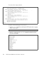
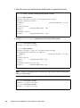
The showhardconf output continued:
PSU#0 Status:Normal; Serial:EA08260208;
+ FRU-Part-Number:CA01022-0720 03C /300-2193-03
;
+ Power_Status:On;
+ Type:AC;
PSU#1 Status:Normal; Serial:EA08260210;
+ FRU-Part-Number:CA01022-0720 03C /300-2193-03
;
+ Power_Status:On;
+ Type:AC;
FANBP_B Status:Normal; Ver:0101h; Serial:PP082704TD ;
+ FRU-Part-Number:CA20399-B12X 006AB/541-3304-02
FAN_A#0 Status:Normal;
FAN_A#1 Status:Normal;
;
For details, see the showhardconf manual pages.
Chapter 3
Troubleshooting
3-13
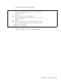
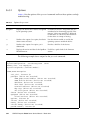
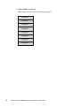
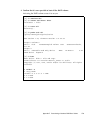
3.5.2
Using the showlogs Command
The showlogs command displays information of specified logs in the order of time
stamps. The information with the oldest time stamp is displayed first. The
showlogs command displays the following logs:
■
Error log
■
Power log
■
Event log
■
Temperature and humidity record
■
Monitoring message log
■
Console message log
■
Panic message log
■
IPL message log
XSCF> showlogs error
Date: Jun 17 11:05:32 JST 2008
Code: 80000000-c3ff0000-0173000600000000
Status: Alarm
Occurred: Jun 17 11:05:32.522 JST 2008
FRU: /PSU#1
Msg: PSU shortage
Date: Jun 17 13:41:46 JST 2008
Code: 80002080-7801c201-0130000000000000
Status: Alarm
Occurred: Jun 17 13:41:44.861 JST 2008
FRU: /MBU_A,*
Msg: Board control error (MBC link error)
Date: Jun 17 13:46:31 JST 2008
Code: 60000000-cd01c701-0164010100000000
Status: Warning
Occurred: Jun 17 13:46:31.158 JST 2008
FRU: /OPNL,/FANBP_B
Msg: TWI access error
XSCF>
3-14
SPARC Enterprise M3000 Server Service Manual • March 2012
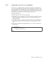
3.5.3
Using the showstatus Command
The showstatus command displays information about faulty or degraded units
that are among the FRUs composing the server and information on the units on the
layers immediately above the layers of the faulty or degraded units. For each of the
displayed units, an asterisk (*) indicating that the unit is faulty is displayed with any
of the following status indicators, which is displayed after "Status:".
■
Normal: Normal state
■
Faulted: The unit is faulty and is not operating.
■
Degraded: The unit is operating. The unit is partly faulty or degraded and some
error has been detected. Although a faulty state is displayed for the unit, it is
operating normally.
■
Deconfigured: There is no problem with the unit itself, but it is degraded due to a
configuration problem, environmental problem, or the degradation of another
unit.
■
Maintenance: Maintenance is being performed. replacefru(8) or addfru(8) is
being executed.
XSCF> showstatus
FANBP_B Status:Normal;
*
FAN_A#0 Status:Faulted;
XSCF>
Chapter 3
Troubleshooting
3-15
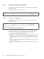
3.5.4
Using the fmdump Command
The fmdump command displays the contents of the log managed by the module
called Fault Manager.
This example assumes that only one error exists.
# fmdump
TIME
UUID
SUNW-MSG-ID
Nov 02 10:04:15.4911 0ee65618-2218-4997-c0dc-b5c410ed8ec2 SUN4-8000-0Y
3.5.4.1
fmdump -V Command
To get more detailed information you can use the -e option, as shown in the
following example.
# fmdump -V -u 0ee65618-2218-4997-c0dc-b5c410ed8ec2
TIME
UUID
Nov 02 10:04:15.4911 0ee65618-2218-4997-c0dc-b5c410ed8ec2
100% fault.io.fire.asic
FRU: hc://product-id=SUNW,A70/motherboard=0
rsrc: hc:///motherboard=0/hostbridge=0/pciexrc=0
SUNW-MSG-ID
SUN4-8000-0Y
The output method using the -V option displays at least three additional lines.
3-16
■
The first line is the same information shown for console messages above,
including a time stamp, UUID, and message ID.
■
The second line is a declaration of the certainty of diagnosis. In this case we are
100 percent sure the failure is in the ASIC described. If the diagnosis may involve
multiple components, you may see two lines here with 50% in each of the two
lines.
■
The "FRU" line indicates what component must be replaced to return the server to
a fully operational state.
■
The "rsrc" line indicates the component that has become unusable because of this
error.
SPARC Enterprise M3000 Server Service Manual • March 2012
3.5.4.2
fmdump -e Command
To get information of the errors that caused this failure you can use the -e option, as
shown in the following example.
# fmdump -e
TIME
CLASS
Nov 02 10:04:14.3008 ereport.io.fire.jbc.mb_per
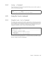
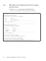
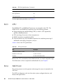
3.5.5
Using the fmadm Command
3.5.5.1
Using the fmadm faulty Command
The fmadm faulty command can be used by administrators and service personnel to
view and modify system configuration parameters that are maintained by the Oracle
Solaris Fault Manager. The command is primarily used to determine the status of a
component involved in a fault, as shown in the following example:
# fmadm faulty
STATERESOURCE / UUID
-------- -------------------------------------------------------degraded dev:////pci@1e,600000
0ee65618-2218-4997-c0dc-b5c410ed8ec2
# fmadm repair
0ee65618-2218-4997-c0dc-b5c410ed8ec2
The PCIe slot has been degraded and it is associated with the same UUID as above.
Also, the "faulted" status may be displayed.
Chapter 3
Troubleshooting
3-17
3.5.5.2
fmadm repair Command
When the fmadm faulty command displays a fault, the fmadm repair command
must be executed to clear the FRU information in the domain after replacement of
the motherboard unit that has encountered the error. If the fmadm repair
command is not executed, the error message is not cleared.
If the fmadm faulty command displays a fault, clearing the FMA resource cache
on the operating system side causes no problem. Data in the cache does not need to
match the hardware fault information held by the XSCF.
# fmadm repair
STATERESOURCE / UUID
-------- -------------------------------------------------------degraded dev:////pci@1e,600000
0ee65618-2218-4997-c0dc-b5c410ed8ec2
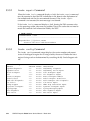
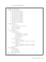
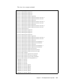
3.5.5.3
fmadm config Command
The fmadm config command output displays the version number and current
status of the diagnosis engine that is being used by the server. Whether the latest
engine is being used can be determined by consulting the My Oracle Support web
site.
# fmadm config
MODULE
cpumem-diagnosis
cpumem-retire
disk-transport
eft
event-transport
fabric-xlate
fmd-self-diagnosis
io-retire
snmp-trapgen
sysevent-transport
syslog-msgs
zfs-diagnosis
zfs-retire
3-18
VERSION
1.6
1.1
1.0
1.16
2.0
1.0
1.0
1.0
1.0
1.0
1.0
1.0
1.0
STATUS
active
active
active
active
active
active
active
active
active
active
active
active
active
DESCRIPTION
CPU/Memory Diagnosis
CPU/Memory Retire Agent
Disk Transport Agent
eft diagnosis engine
Event Transport Module
Fabric Ereport Translater
Fault Manager Self-Diagnosis
I/O Retire Agent
SNMP Trap Generation Agent
SysEvent Transport Agent
Syslog Messaging Agent
ZFS Diagnosis Engine
ZFS Retire Agent
SPARC Enterprise M3000 Server Service Manual • March 2012
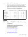
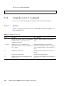
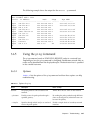
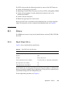
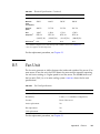
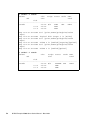
3.5.6
Using the fmstat Command
The fmstat command reports statistical information and a set of modules that are
associated with the module called Oracle Solaris Fault Manager. By using the
fmstat command, statistical information about the diagnostic engine and
diagnostic agent that are currently involved in fault management can be displayed.
The following output example shows that the fmd-self-diagnosis DE module
(displayed also on the console output) has received accepted events.
# fmstat
module
ev_recv ev_acpt wait svc_t %w %b open solve memsz
cpumem-diagnosis
0
0 0.0
0.0
0
0
0
0
3.0K
cpumem-retire
0
0 0.0
0.0
0
0
0
0
0
disk-transport
0
0 0.0 1793.8
0
0
0
0
40b
eft
0
0 0.0
0.0
0
0
0
0
1.2M
event-transport
0
0 0.0
0.0
0
0
0
0
210b
fabric-xlate
0
0 0.0
0.0
0
0
0
0
0
fmd-self-diagnosis
0
0 0.0
0.0
0
0
0
0
0
io-retire
0
0 0.0
0.0
0
0
0
0
0
snmp-trapgen
0
0 0.0
0.0
0
0
0
0
32b
sysevent-transport
0
0 0.0 2395.3
0
0
0
0
0
syslog-msgs
0
0 0.0
0.0
0
0
0
0
0
zfs-diagnosis
0
0 0.0
0.0
0
0
0
0
0
zfs-retire
0
0 0.0
0.0
0
0
0
0
0
3.6
bufsz
0
0
0
0
0
0
0
0
0
0
0
0
0
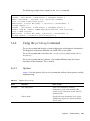
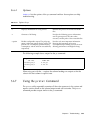
General Oracle Solaris Troubleshooting
Commands
Superuser commands of this type are useful to determine whether there is a problem
with the server, network, or another server connected via the network.
This section explains the following commands:
■
“Using the iostat Command” on page 3-20
■
“Using the prtdiag Command” on page 3-21
■
“Using the prtconf Command” on page 3-23
■
“Using the netstat Command” on page 3-26
■
“Using the ping Command” on page 3-27
■
“Using the ps Command” on page 3-28
■
“Using the prstat Command” on page 3-29
Chapter 3
Troubleshooting
3-19
Most of these commands are located in the /usr/bin directory or /usr/sbin
directory.
3.6.1
Using the iostat Command
The iostat command repeatedly reports terminal, drive, and I/O activity, as well
as CPU utilization.
3.6.1.1
Options
TABLE 3-7 lists the options of the iostat command and how those options can help
troubleshoot the server.
TABLE 3-7
Options for iostat
Option
Description
How It Can Help
No option
Reports status of local I/O devices.
A quick three-line output of device status
information.
-c
Reports the percentages of time the system has Quick report of CPU status
spent in user mode, in system mode, waiting
for I/O, and idling.
-e
Displays device error summary statistics.
Displays the total number of errors, hardware
errors, software errors, and transfer errors.
Provides a short table with accumulated
errors. Identifies suspect I/O devices.
-E
Displays all device error statistics.
Provides information about devices:
manufacturer, model number, serial number,
size, and errors.
-n
Displays names in a descriptive format.
The descriptive format helps identify devices.
-x
Reports extended drive statistics of each drive. Similar to the -e option, but provides rate
The output is in a tabular form.
information. This helps identify internal
devices with poor performance and other I/O
devices with poor performance across the
network.
3-20
SPARC Enterprise M3000 Server Service Manual • March 2012
The following example shows output for the iostat command:
# iostat -En
c0t0d0
Soft Errors: 0 Hard Errors: 0 Transport Errors: 0
Model: ST3120026A
Revision: 8.01 Serial No: 3JT4H4C2
Size: 120.03GB <120031641600 bytes>
Media Error: 0 Device Not Ready: 0 No Device: 0 Recoverable: 0
Illegal Request: 0
c0t2d0
Soft Errors: 0 Hard Errors: 0 Transport Errors: 0
Vendor: LITE-ON Product: COMBO SOHC-4832K Revision: O3K1 Serial No:
Size: 0.00GB <0 bytes>
Media Error: 0 Device Not Ready: 0 No Device: 0 Recoverable: 0
Illegal Request: 0 Predictive Failure Analysis: 0
3.6.2
Using the prtdiag Command
The prtdiag command displays system configuration and diagnostic information.
The diagnostic information identifies any failed FRU in the system.
The prtdiag command is located in the /usr/platform/platform-name/sbin/
directory.
The prtdiag command may indicate a slot number different from that shown
elsewhere in this document. This is normal.
3.6.2.1
Options
TABLE 3-8 lists the options of the prtdiag command and how those options can help
troubleshooting.
TABLE 3-8
Options for prtdiag
Option
Description
How it can help
No option
Lists components.
Shows CPU information, memory
configuration, PCIe cards installed, OBP
version, status of the mode switch, and CPU
operation mode.
-v
Verbose mode.
Provides the same information as no option.
Additionally, displays the detail information
of PCIe cards.
Chapter 3
Troubleshooting
3-21
The following example shows output for the prtdiag command in verbose mode:
# prtdiag -v
System Configuration: Sun Microsystems
System clock frequency: 1064 MHz
Memory size: 7808 Megabytes
sun4u SPARC Enterprise M3000 Server
================================== CPUs ===========================
LSB
--00
CPU
Chip
---0
CPU
ID
----------------------0, 1, 2, 3, 4, 5, 6, 7
Run
MHz
---2520
L2$
MB
--5.0
CPU
Impl.
----7
CPU
Mask
---145
=================== Memory Configuration ==========================
Memory
LSB Group
--- -----00
A
00
B
Available
Size
-----------4096MB
3712MB
Memory
Status
------okay
okay
DIMM
# of Mirror Interleave
Size
DIMMs Mode
Factor
------ ----- ------- ---------1024MB
4
no
2-way
1024MB
4
no
2-way
========================= IO Devices =============================
IO
Lane/Frq
LSB Type LPID RvID,DvID,VnID
BDF
State Act,Max
Name
Model
Logical Path
--- ----- ---- --------------- ------- ----- -------- ----------------- -----------------------------------00 PCIe 0
aa, 8533, 10b5
2, 0, 0 okay 8, 8
N/A
/pci@0,600000/pci@0
00 PCIe 0
aa, 8533, 10b5
3, 0, 0 okay 4, 8
N/A
/pci@0,600000/pci@0/pci@0
00 PCIe 0
aa, 8533, 10b5
3, 1, 0 okay 4, 4
N/A
/pci@0,600000/pci@0/pci@1
00 PCIe 0
aa, 8533, 10b5
3, 2, 0 okay 4, 4
N/A
/pci@0,600000/pci@0/pci@2
00 PCIe 0
aa, 8533, 10b5
3, 8, 0 okay 0, 8
N/A
/pci@0,600000/pci@0/pci@8
00 PCIe 0
8,
58, 1000
4, 0, 0 okay 4, 8
LSI,1068E /pci@0,600000/pci@0/pci@0/scsi@0
00 PCIx 0
b5, 103, 1166
5, 0, 0 okay 133,133
N/A
/pci@0,600000/pci@0/pci@1/pci@0
00 PCI
0
a3, 1678, 14e4
6, 4, 0 okay --,133
N/A
/pci@0,600000/pci@0/pci@1/pci@0/network@4
3-22
SPARC Enterprise M3000 Server Service Manual • March 2012
pci-pciex10b5,8533
pci-pciex10b5,8533
pci-pciex10b5,8533
pci-pciex10b5,8533
pci-pciex10b5,8533
scsi-pciex1000,58
pci-pciex1166,103
network-pci14e4,1678
The prtdiag output continued:
00 PCI
0
a3, 1678, 14e4
6, 4, 1 okay --,133 network-pci14e4,1678
N/A
/pci@0,600000/pci@0/pci@1/pci@0/network@4,1
00 PCIx 0
b5, 103, 1166
7, 0, 0 okay 133,133 pci-pciex1166,103
N/A
/pci@0,600000/pci@0/pci@2/pci@0
00 PCI
0
a3, 1678, 14e4
8, 4, 0 okay --,133 network-pci14e4,1678
N/A
/pci@0,600000/pci@0/pci@2/pci@0/network@4
00 PCI
0
a3, 1678, 14e4
8, 4, 1 okay --,133 network-pci14e4,1678
N/A
/pci@0,600000/pci@0/pci@2/pci@0/network@4,1
00 PCIe 1
aa, 8533, 10b5
2, 0, 0 okay
8, 8 pci-pciex10b5,8533
N/A
/pci@1,700000/pci@0
00 PCIe 1
aa, 8533, 10b5
3, 0, 0 okay
0, 8 pci-pciex10b5,8533
N/A
/pci@1,700000/pci@0/pci@0
00 PCIe 1
aa, 8533, 10b5
3, 8, 0 okay
0, 8 pci-pciex10b5,8533
N/A
/pci@1,700000/pci@0/pci@8
00 PCIe 1
aa, 8533, 10b5
3, 9, 0 okay
0, 8 pci-pciex10b5,8533
N/A
/pci@1,700000/pci@0/pci@9
==================== Hardware Revisions ====================
System PROM revisions:
---------------------OBP 4.24.8 2008/04/23 15:15
=================== Environmental Status ===================
Mode switch is in LOCK mode
=================== System Processor Mode ===================
SPARC64-VII mode
#
3.6.3
Using the prtconf Command
Similar to the show-devs command executed at the ok prompt, the prtconf
command displays the devices that are configured.
The prtconf command identifies hardware that is recognized by the Oracle Solaris
OS. If software applications are having problems with hardware but the hardware is
not suspected of being faulty, the prtconf command can be used to check whether
the Oracle Solaris software recognizes the hardware and whether a driver for the
hardware is loaded.
Chapter 3
Troubleshooting
3-23
3.6.3.1
Options
TABLE 3-9 lists the options of the prtconf command and how those options can help
troubleshooting.
TABLE 3-9
Options for prtconf
Option
Description
How it can help
No option
Displays the device tree of devices recognized
by the operating system.
If a hardware device is recognized, then it is
considered to be functioning properly. If the
message "(driver not attached)" is displayed
for the device or sub-device, then the driver
for the device is corrupt or missing.
-D
Similar to the output of no option, but device
driver names are listed.
Lists the drivers needed or used by the
operating system to enable the device.
-p
Similar to the output of no option, yet is
abbreviated.
Provides a brief list of the devices.
-V
Displays the version and date of the OpenBoot Useful for a quick check of the firmware
PROM firmware.
version.
The following example shows output for the prtconf command:
# prtconf
System Configuration: Sun Microsystems
Memory size: 7616 Megabytes
System Peripherals (Software Nodes):
sun4u
SUNW,SPARC-Enterprise
scsi_vhci, instance #0
packages (driver not attached)
SUNW,probe-error-handler (driver not attached)
SUNW,builtin-drivers (driver not attached)
deblocker (driver not attached)
disk-label (driver not attached)
terminal-emulator (driver not attached)
obp-tftp (driver not attached)
ufs-file-system (driver not attached)
chosen (driver not attached)
openprom (driver not attached)
client-services (driver not attached)
options, instance #0
aliases (driver not attached)
memory (driver not attached)
virtual-memory (driver not attached)
pseudo-console, instance #0
3-24
SPARC Enterprise M3000 Server Service Manual • March 2012
The prtconf output continued:
nvram (driver not attached)
pseudo-mc, instance #0
cmp (driver not attached)
core (driver not attached)
cpu (driver not attached)
cpu (driver not attached)
core (driver not attached)
cpu (driver not attached)
cpu (driver not attached)
core (driver not attached)
cpu (driver not attached)
cpu (driver not attached)
core (driver not attached)
cpu (driver not attached)
cpu (driver not attached)
pci, instance #0
ebus, instance #0
flashprom (driver not attached)
serial, instance #0
scfc, instance #0
panel, instance #0
pci, instance #0
pci, instance #0
pci, instance #1
scsi, instance #0
tape (driver not attached)
disk (driver not attached)
sd, instance #1
sd, instance #0
pci, instance #2
pci, instance #0
network, instance #0
network, instance #1 (driver not attached)
pci, instance #3
pci, instance #1
network, instance #2 (driver not attached)
network, instance #3 (driver not attached)
pci, instance #4
pci, instance #1
pci, instance #5
pci, instance #6
pci, instance #7
pci, instance #8
os-io (driver not attached)
iscsi, instance #0
Chapter 3
Troubleshooting
3-25
The prtconf output continued:
pseudo, instance #0
#
3.6.4
Using the netstat Command
The netstat command displays the network status and protocol statistics.
3.6.4.1
Options
TABLE 3-10 lists the options of the netstat command and how those options can
help troubleshooting.
Options for netstat
TABLE 3-10
Option
Description
How It Can Help
-i
Displays the interface status. The information
includes packets in/out, errors in/out,
collisions, and queues.
Provides a quick overview of the network
status.
-i interval
Repeats the setstat command in the
intervals of as many seconds as specified after
the -i option.
Identifies intermittent or long duration
network events. By piping setstat output to
a file, overnight activity can be viewed all at
once.
-p
Displays the media table.
Provides the MAC address for hosts on the
subnet.
-r
Displays the routing table.
Provides routing information.
-n
Replaces host names with IP addresses and
displays them.
Used when an IP address is more useful than a
host name.
3-26
SPARC Enterprise M3000 Server Service Manual • March 2012
The following example shows the output for the netstat -p command:
# netstat -p
Net to Media Table: IPv4
Device
IP Address
------ -------------------bge0
san-ff1-14-a
bge0
san-ff2-40-a
sppp0 224.0.0.22
bge0
san-ff2-42-a
bge0
san09-lab-r01-66
sppp0 192.168.1.1
bge0
san-ff2-9-b
bge0
bizzaro
bge0
san-ff2-9-a
bge0
racerx-b
bge0
224.0.0.0
#
3.6.5
Mask
--------------255.255.255.255
255.255.255.255
255.255.255.255
255.255.255.255
255.255.255.255
255.255.255.255
255.255.255.255
255.255.255.255
255.255.255.255
255.255.255.255
240.0.0.0
Flags
Phys Addr
-------- --------------o
00:14:4f:3a:93:61
o
00:14:4f:3a:93:85
o
o
00:14:4f:3a:93:af
00:e0:52:ec:1a:00
o
o
o
o
SM
00:03:ba:dc:af:2a
00:03:ba:11:b3:c1
00:03:ba:dc:af:29
00:0b:5d:dc:08:b0
01:00:5e:00:00:00
Using the ping Command
The ping command sends an ICMP ECHO_REQUEST packet to a network host.
Depending on how the ping command is configured, troublesome network links or
nodes can be identified from the displayed output. The destination host is specified
in the variable hostname.
3.6.5.1
Options
TABLE 3-11 lists the options of the ping command and how those options can help
troubleshooting.
TABLE 3-11
Options for ping
Option
Description
How it can help
hostname
The probe packet is sent to hostname and
returned.
Verifies that a host is active on the network.
-g hostname
Forcibly routes the probe packet through a
specified gateway.
By sending the probe packet through different
routes to the target host, individual routes can
be tested for quality.
-i interface
Specifies through which interface to send and
receive the probe packet.
Enables a simple check of secondary network
interfaces.
Chapter 3
Troubleshooting
3-27
TABLE 3-11
Options for ping (Continued)
Option
Description
How it can help
-n
Replaces host names with IP addresses and
displays them.
Used when an IP address is more useful than a
host name.
-s
Continues to repeat ping at intervals of 1
second. Pressing CTRL-C stops the execution.
After it is stopped, statistics are displayed.
Helps identify intermittent or long duration
network events. By piping ping output to a
file, overnight activity can be viewed all at
once.
-svR
Displays the route the probe packet followed
in 1-second intervals.
Indicates the probe packet route and number
of hops. Comparing multiple routes can
identify bottlenecks.
The following example shows output for the ping -s command:
# ping -s san-ff2-17-a
PING san-ff2-17-a: 56 data bytes
64 bytes from san-ff2-17-a (10.1.67.31): icmp_seq=0. time=0.427 ms
64 bytes from san-ff2-17-a (10.1.67.31): icmp_seq=1. time=0.194 ms
^C
----san-ff2-17-a PING Statistics---2 packets transmitted, 2 packets received, 0% packet loss
round-trip (ms) min/avg/max/stddev = 0.172/0.256/0.427/0.102
#
3.6.6
Using the ps Command
The ps commands lists the status of processes. If no option is specified, the ps
command outputs information about the processes that have the same execution user
ID as the user who is executing this command and are controlled from the same
control terminal as this command.
If any option is specified, the output information is controlled according to the
specified option.
3-28
SPARC Enterprise M3000 Server Service Manual • March 2012
3.6.6.1
Options
TABLE 3-12 lists the options of the ps command and how those options can help
troubleshooting.
TABLE 3-12
Options for ps
Option
Description
How It Can Help
-e
Displays information for every process.
Identifies the process ID and the executable
files.
-f
Generates a full listing.
Provides the following process information:
user ID, parent process ID, time when
executed, and the paths to the executable files.
-o option
Enables configurable output. The pid, pcpu,
pmem, and comm options display process ID,
percent CPU consumption, percent memory
consumption, and the relevant executable file,
respectively.
Provides only most important information.
Knowing the percentage of resource
consumption helps identify processes that are
affecting performance and might be hung.
The following example shows output for the ps command:
# ps
PID TTY
101042 pts/3
101025 pts/3
#
TIME CMD
0:00 ps
0:00 sh
When using sort with the -r option, the column headings are output so that the
value in the first column is equal to zero.
3.6.7
Using the prstat Command
The prstat utility repeatedly examines all the active processes in the system and
reports statistics based on the selected output mode and sort order. The prstat
command provides output similar to the ps command.
Chapter 3
Troubleshooting
3-29
3.6.7.1
Options
TABLE 3-13 lists the options of the prstat command and how those options can help
troubleshooting.
TABLE 3-13
Options for prstat
Option
Description
How It Can Help
No option
Output identifies the process ID, user ID, used
Displays a list of the processes sorted in
amount of memory, state, CPU consumption,
descending order of consumption amount of
CPU resources. The list is limited to the height and command name.
of the terminal window and the total number
of processes. Output is automatically updated
every 5 seconds. Pressing CTRL-C stops the
execution.
-n number
Limits the number of output lines.
Limits the amount of data displayed and
displays processes consuming many resources.
-s key
Enables the sorting of list contents by key
parameter.
Useful keys are cpu (default), time, and size.
-v
Verbose mode
Displays additional parameters.
The following example shows output for the prstat command:
# prstat -n 5 -s size
PID USERNAME SIZE RSS STATE PRI NICE
TIME CPU PROCESS/NLWP
100463 root
66M
61M sleep
59
0 0:01:03 0.0% fmd/19
100006 root
11M 9392K sleep
59
0 0:00:09 0.0% svc.configd/16
100004 root
10M 8832K sleep
59
0 0:00:04 0.0% svc.startd/14
100061 root
9440K 6624K sleep
59
0 0:00:01 0.0% snmpd/1
100132 root
8616K 5368K sleep
59
0 0:00:04 0.0% nscd/35
Total: 52 processes, 188 lwps, load averages: 0.00, 0.00, 0.00
#
3-30
SPARC Enterprise M3000 Server Service Manual • March 2012
CHAPTER
4
FRU Replacement Preparation
This chapter explains the method of preparing for the safe replacement of FRUs.
4.1
■
Section 4.1, “Tools Required for Maintenance” on page 4-1
■
Section 4.2, “FRU Replacement and Installation Methods” on page 4-2
■
Section 4.3, “Active Replacement/Active Addition” on page 4-5
■
Section 4.4, “Hot Replacement/Hot Addition” on page 4-7
■
Section 4.5, “Cold Replacement/Cold Addition” on page 4-12
Tools Required for Maintenance
The actual maintenance work described in Chapter 5 to Chapter 15 requires
maintenance software to confirm that the server and other components are operating
correctly and to collect status information and log data on the server and
components. Work for mounting, removing, or replacing a specific component
requires special tools, including screwdrivers and an antistatic wrist strap. These
items are generally named maintenance tools and are listed in TABLE 4-1.
TABLE 4-1
Maintenance Tools
Item
Part Name
Use
1
Phillips screwdriver (No. 2)
2
Wrist strap
For electrostatic control
3
Conductive mat
For electrostatic control
4
Oracle VTS
Test program
4-1
4.2
FRU Replacement and Installation
Methods
This section explains how to replace and install FRUs.
4.2.1
FRU Replacement
There are three methods of replacing FRUs, as follows:
■
Active replacement
A target FRU is operated while the Oracle Solaris OS of the domain to which the
FRU belongs is operating.
The target FRU is operated by using Oracle Solaris OS commands or XSCF
commands.
Because the power supply unit (PSU) and fan unit (FAN) do not belong to any
domain, they are operated by using XSCF commands regardless of the operating
state of the Oracle Solaris OS.
Note – The hard disk drive will have a redundant configuration by setting the
mirroring.
Note – ■ If a hard disk drive is a nonmirrored boot device, it must be replaced
according to the cold replacement procedure.
■ If a hard disk drive is in a mirrored configuration, active replacement can be
performed on the failed drive because the mirrored hard disk drive continues to be
online and functioning. The hard disk replacement procedure varies by the
mirroring configuration method. When it is configured with hardware RAID, see the
SPARC Enterprise M3000/M4000/M5000/M8000/M9000 Servers Administration Guide.
When it is configured with software RAID, see the manuals for the software in use.
Note – Hardware RAID is available only on the M3000 server with the SPARC64
VII+ processors.
Note – To activate a hardware RAID boot volume after replacing the MBU of an
M3000 server with SPARC64 VII+ processors, see Appendix F.
4-2
SPARC Enterprise M3000 Server Service Manual • March 2012
■
Hot replacement
A target FRU is operated while the domain to which the FRU belongs is stopped.
Depending on the target FRU, there are two cases as follows:
■
■
Power supply unit/Fan unit: operated with XSCF commands.
■
Hard disk drive: operated directly, not by using XSCF commands.
Cold replacement
After all the domains are stopped and then the server is powered off, a FRU is
operated.
Note – Do not operate a target FRU while the OpenBoot PROM is running (the ok
prompt is displayed). After stopping the relevant domain (power-off) or starting the
Oracle Solaris OS, operate the target FRU.
TABLE 4-2 lists the access locations and applicable replacement methods for each
FRU.
TABLE 4-2
FRU Access Locations and Replacement Methods
Access
Location
Cold
Replacement
Hot
Replacement
Active
Replacement
Where to Find the
Procedure
Top
Yes
No
No
Chapter 6
Memory (DIMM)
Top
Yes
No
No
Chapter 7
PCIe card (PCIe)
Top
Yes
No
FRU
Motherboard unit
(MBU_A, MBU_A_2, MBU_A_3,
MBU_A_4, MBU_A_5, MBU_A_6)
Hard disk drive (HDD)
Front
No
*
Chapter 8
‡
Yes
Yes
Hard disk drive backplane (HDDBP) Top
Yes
No
No
Chapter 10
CD-RW/DVD-RW drive unit
(DVDU)
Front/top
Yes
No
No
Chapter 11
Power supply unit (PSU)
Rear
Yes
Yes †
Yes †
Chapter 12
†
†
Chapter 13
Yes
Yes
Chapter 9
Fan unit (FAN_A)
Top
Yes
Yes
Fan backplane (FANBP_B)
Top
Yes
No
No
Chapter 14
Operator panel (OPNL)
Front/top
Yes
No
No
Chapter 15
* The FRU is operated directly, without using XSCF commands.
† The FRU is operated with XSCF commands.
Chapter 4
FRU Replacement Preparation
4-3
‡
The hard disk drive will have a redundant configuration by setting the mirroring.
If a hard disk drive is a nonmirrored boot device, it must be replaced according to the cold replacement procedure.
■ If a hard disk drive is in a mirrored configuration, active replacement can be performed on the failed drive because the mirrored
hard disk drive continues to be online and functioning. The hard disk replacement procedure varies by the mirroring configuration
method. When it is configured with hardware RAID, see the SPARC Enterprise M3000/M4000/M5000/M8000/M9000 Servers Administration Guide. When it is configured with software RAID, see the manuals for the software in use.
■
■
4.2.2
FRU Installation
For empty slots without hard disk drives or PCIe cards, the number of mounted
FRUs can be changed from 1 to the maximum number as required. There are some
components that are tentatively mounted physically in the server. If such a
component is a hard disk drive, it is called an HDD dummy, and if such a
component is a PCIe card, it is called a PCIe slot cover. These components are
necessary to protect the server from noise and to properly cool the server.
The same methods as those used for replacement are used for installation.
Note – When installing a new FRU in an empty slot, remove the HDD dummy or
PCIe slot cover and then install a new FRU.
TABLE 4-3 lists the access location and applicable installation methods for each FRU.
TABLE 4-3
FRU Access Locations and Installation Methods
Access
Location
Cold Addition Hot Addition
Active
Addition
Top
No
No
No
Memory (DIMM)
Top
Yes
No
No
Chapter 7
PCIe card (PCIe)
Top
Yes
No
No
Chapter 8
Front
Yes
Yes *
Yes†
Chapter 9
Hard disk drive backplane (HDDBP) Top
No
No
No
CD-RW/DVD-RW drive unit
(DVDU)
Front/top
No
No
No
Power supply unit (PSU)
Rear
No
No
No
Fan unit (FAN_A)
Top
No
No
No
Fan backplane (FANBP_B)
Top
No
No
No
FRU
Motherboard unit
(MBU_A, MBU_A_2, MBU_A_3,
MBU_A_4, MBU_A_5, MBU_A_6)
Hard disk drive (HDD)
4-4
SPARC Enterprise M3000 Server Service Manual • March 2012
Where to Find the
Procedure
TABLE 4-3
FRU Access Locations and Installation Methods (Continued)
FRU
Access
Location
Cold Addition Hot Addition
Active
Addition
Operator panel (OPNL)
Front/top
No
No
No
Where to Find the
Procedure
* The FRU is operated directly, without using XSCF commands.
† The FRU is operated with XSCF commands.
4.3
Active Replacement/Active Addition
In active replacement, the target FRU is operated while the Oracle Solaris OS of the
domain to which the FRU belongs is operating.
The target FRU is operated using Oracle Solaris OS commands or XSCF commands.
Because the power supply unit (PSU) and fan unit (FAN) do not belong to any
domain, they are operated by using XSCF commands regardless of the operating
state of the Oracle Solaris OS.
Active replacement has the following four stages:
■
“Releasing a FRU from a Domain” on page 4-5
■
“FRU Removal and Replacement” on page 4-6
■
“Configuring a FRU in a Domain” on page 4-6
■
“Verifying the Hardware Operation” on page 4-7
For active installation, see Section 4.3.3, “Configuring a FRU in a Domain” on
page 4-6 and "Section 4.3.4, “Verifying the Hardware Operation” on page 4-7.
4.3.1
Releasing a FRU from a Domain
Note – ■ If a hard disk drive is a nonmirrored boot device, it must be replaced
according to the cold replacement procedure.
■ If a hard disk drive is in a mirrored configuration, active replacement can be
performed on the failed drive because the mirrored hard disk drive continues to be
online and functioning.
Chapter 4
FRU Replacement Preparation
4-5
1. From the Oracle Solaris OS, type the cfgadm command to obtain the FRU
status.
# cfgadm -a
2. Stop the application from using the FRU and disconnect the FRU from the
Oracle Solaris OS.
The READY LED (green) of the HDD goes off.
3. Type the cfgdevice -c unconfigure command to disconnect the FRU from
the Oracle Solaris OS.
# cfgadm -c unconfigure Ap_Id
4. Type the cfgadm -x command to confirm that the CHECK LED blinks.
# cfgadm -x led=fault, mode=blink Ap_Id
The Ap_Id is shown in the output of cfgadm (for example, disk#0).
The CHECK LED (amber) of the HDD blinks.
5. Type the cfgadm command to verify that the FRU has been disconnected.
# cfgadm -a
The disconnected FRU is displayed as being unconfigured.
4.3.2
FRU Removal and Replacement
After the disconnection of a FRU from a domain, the same procedure as that for Hot
Replacement/Hot Addition applies. See Section 4.4, “Hot Replacement/Hot
Addition” on page 4-7.
4.3.3
Configuring a FRU in a Domain
This section explains the procedure for active replacement/installation by using
Oracle Solaris OS commands. For information on using the XSCF command, see
Section 4.4, “Hot Replacement/Hot Addition” on page 4-7.
4-6
SPARC Enterprise M3000 Server Service Manual • March 2012
1. Type the cfgdevice -c unconfigure command from the Oracle Solaris OS
to integrate the FRU into the Oracle Solaris OS.
# cfgadm -c configure Ap_Id
The Ap_Id is shown in the output of cfgadm (for example, disk#0).
2. Type the cfgadm -x command to confirm that the CHECK LED is off.
# cfgadm -x led=fault, mode=off Ap_Id
The Ap_Id is shown in the output of cfgadm (for example, disk#0).
The CHECK LED (amber) of the HDD is turned off.
3. Type the cfgadm command to verify that the FRU has been configured.
# cfgadm -a
The configured FRU is displayed as being configured.
The READY LED (green) of the HDD goes on.
4.3.4
Verifying the Hardware Operation
■
Confirm the status of the LED indicators.
For information on the LED status, see TABLE 2-3 and TABLE 2-5.
4.4
Hot Replacement/Hot Addition
In hot replacement, the target FRU is operated while the domain to which the FRU
belongs is stopped.
Depending on the target FRU, there are two cases as follows:
■
Power supply unit/Fan unit: operated with XSCF commands. See Section 4.4.1,
“FRU Removal and Replacement (Power supply unit/Fan unit)” on page 4-8.
■
Hard disk drive: operated directly, not by using XSCF commands.
For hot addition, do the same operation as that for hot replacement.
Chapter 4
FRU Replacement Preparation
4-7
4.4.1
FRU Removal and Replacement (Power supply
unit/Fan unit)
●
Type the replacefru command from the XSCF Shell prompt.
The replacefru command is a menu-driven interactive command.
XSCF> replacefru
---------------------------------------------------------------------Maintenance/Replacement Menu
Please select a type of FRU to be replaced.
1. FAN
(Fan Unit)
2. PSU
(Power Supply Unit)
---------------------------------------------------------------------Select [1,2|c:cancel] :1
---------------------------------------------------------------------Maintenance/Replacement Menu
Please select a FAN to be replaced.
No. FRU
Status
--- --------------- -----------------1. FAN_A#0
Normal
2. FAN_A#1
Normal
---------------------------------------------------------------------Select [1,2|b:back] :1
You are about to replace FAN_A#0.
Do you want to continue?[r:replace|c:cancel] :r
Please confirm the Check LED is blinking.
If this is the case, please replace FAN_A#0.
After replacement has been completed, please select[f:finish] :f
4-8
SPARC Enterprise M3000 Server Service Manual • March 2012
The replacefru command automatically tests the status of the FRU after the
completion of removal and replacement.
Diagnostic tests for FAN_A#0 have started.
[This operation may take up to 3 minute(s)]
(progress scale reported in seconds)
0..... 30..done
---------------------------------------------------------------------Maintenance/Replacement Menu
Status of the replaced FRU.
FRU
Status
------------- -------FAN_A#0
Normal
---------------------------------------------------------------------The replacement of FAN_A#0 has completed normally.[f:finish] :f
---------------------------------------------------------------------Maintenance/Replacement Menu
Please select a type of FRU to be replaced.
1. FAN
(Fan Unit)
2. PSU
(Power Supply Unit)
---------------------------------------------------------------------Select [1,2|c:cancel] :c
Note – The display may vary depending on the XCP version
When the tests are complete, the program displays the original menu again. To
return to the XSCF Shell prompt, select cancel.
For details, see the manual pages of replacefru.
Chapter 4
FRU Replacement Preparation
4-9
4.4.2
Verifying the Hardware Operation (Power supply
unit/Fan unit)
1. Type the showhardconf command to confirm that the new FRU has been
installed.
XSCF> showhardconf
SPARC Enterprise M3000;
+ Serial:IKK0813023; Operator_Panel_Switch:Locked;
+ Power_Supply_System:Single; SCF-ID:XSCF#0;
+ System_Power:On; System_Phase:Cabinet Power On;
Domain#0 Domain_Status:OpenBoot Execution Completed;
MBU_A Status:Normal; Ver:0101h; Serial:PP082202QX ;
+ FRU-Part-Number:CA07082-D901 A1
/541-3302-01
;
+ CPU Status:Normal;
+ Freq:2.520 GHz; Type:32;
+ Core:4; Strand:2;
+ Memory_Size:8 GB;
MEM#0A Status:Normal;
+ Code:ce0000000000000001M3 93T2950EZA-CE6 4145-473b3c23;
+ Type:1A; Size:1 GB;
MEM#0B Status:Normal;
+ Code:7f7ffe00000000004aEBE10RD4AJFA-5C-E 3020-223b2918;
+ Type:1A; Size:1 GB;
MEM#1A Status:Normal;
+ Code:7f7ffe00000000004aEBE10RD4AJFA-5C-E 3020-223b28af;
+ Type:1A; Size:1 GB;
MEM#1B Status:Normal;
+ Code:7f7ffe00000000004aEBE10RD4AJFA-5C-E 3020-223b28ab;
+ Type:1A; Size:1 GB;
MEM#2A Status:Normal;
+ Code:7f7ffe00000000004aEBE10RD4AJFA-5C-E 3020-223b283e;
+ Type:1A; Size:1 GB;
MEM#2B Status:Normal;
+ Code:7f7ffe00000000004aEBE10RD4AJFA-5C-E 3020-223b2829;
+ Type:1A; Size:1 GB;
MEM#3A Status:Normal;
+ Code:7f7ffe00000000004aEBE10RD4AJFA-5C-E 3020-223b2840;
+ Type:1A; Size:1 GB;
MEM#3B Status:Normal;
+ Code:7f7ffe00000000004aEBE10RD4AJFA-5C-E 3020-223b2830;
+ Type:1A; Size:1 GB;
PCI#0 Name_Property:fibre-channel; Card_Type:Other;
PCI#1 Name_Property:fibre-channel; Card_Type:Other;
PCI#2 Name_Property:pci; Card_Type:Other;
PCI#3 Name_Property:pci; Card_Type:Other;
4-10
SPARC Enterprise M3000 Server Service Manual • March 2012
The showhardconf output continued:
OPNL Status:Normal; Ver:0101h; Serial:PP082202R8 ;
+ FRU-Part-Number:CA07082-D911 A1
/541-3306-01
PSU#0 Status:Normal; Serial:EA08210127;
+ FRU-Part-Number:CA01022-0720 02B /300-2193-02
;
+ Power_Status:On;
+ Type:AC;
PSU#1 Status:Normal; Serial:EA08210131;
+ FRU-Part-Number:CA01022-0720 02B /300-2193-02
;
+ Power_Status:On;
+ Type:AC;
FANBP_B Status:Normal; Ver:0101h; Serial:PP0821031E ;
+ FRU-Part-Number:CA20399-B12X 004AA/541-3304-01
FAN_A#0 Status:Normal;
FAN_A#1 Status:Normal;
XSCF>
;
;
For details, see the manual pages of showhardconf.
2. Confirm the state of the status LEDs of the FRU.
For information on the LED status, see TABLE 2-3 and TABLE 2-5.
4.4.3
Verifying the Hardware Operation (Hard disk
drive)
●
Type the probe-scsi-all command to confirm that the new hard disk drive
has been installed.
Chapter 4
FRU Replacement Preparation
4-11
4.5
Cold Replacement/Cold Addition
In cold replacement, all business operations must be stopped. When accessing the
server, power off the server and disconnect the power cord to ensure safety.
For cold addition, do the same operation as that for cold replacement.
4.5.1
Powering off the Server
This section explains how to power off the server.
4.5.1.1
Power-off by Using the XSCF Command
1. Notify users that the server is being powered off.
2. Back up the system files and data to tape, if necessary.
3. A user with platadm or fieldeng authority must log in to the XSCF Shell and
enter the poweroff command.
XSCF> poweroff -a
The following activity is executed when the poweroff command is used:
■
The Oracle Solaris OS shuts down completely.
■
The server is powered off and the server enters standby mode. (The power to
the XSCF unit remains on.)
For details, see the SPARC Enterprise M3000/M4000/M5000/M8000/M9000 Servers
XSCF User's Guide.
4. Verify that the POWER LED on the operator panel is off.
5. Disconnect all the power cords from the power outlets.
Caution – There is a risk of electrical failure if the power cords are not
disconnected. All the power cords must be disconnected to completely cut the power
to the server.
4-12
SPARC Enterprise M3000 Server Service Manual • March 2012
4.5.1.2
Power off by Using the Operator Panel
1. Notify users that the server is being powered off.
2. Back up the system files and data to tape, if necessary.
3. Turn the mode switch on the operator panel to the Service position.
4. Press the power switch on the operator panel for 4 seconds or more.
5. Verify that the POWER LED on the operator panel is off.
6. Disconnect all the power cords from the power outlets.
Caution – There is a risk of electrical failure if the power cords are not
disconnected. All the power cords must be disconnected to completely cut the power
to the server.
4.5.2
FRU Removal and Replacement
In cold replacement, a FRU is removed and replaced while the power is turned off.
After the FRU replacement, power on the server.
4.5.3
Powering on the Server
This section explains how to power on the server.
4.5.3.1
Power-on by Using the XSCF Command
1. Verify that the server has enough power supply units to operate in the desired
configuration.
2. Connect all the power cords to power outlets.
3. Verify that the XSCF STANDBY LED on the operator panel is on.
4. Turn the mode switch on the operator panel to the desired mode position
(Locked or Service).
Chapter 4
FRU Replacement Preparation
4-13
5. A user with platadm or fieldeng authority must log in to the XSCF Shell and
type the poweron command.
XSCF> poweron -a
Soon, the following activity is executed:
■
The POWER LED on the operator panel is turned on.
■
The power-on self-test (POST) is executed.
Then, the server is completely powered on.
Note – If automatic startup of the Oracle Solaris OS is specified, use the sendbreak
-d domain_id command of the XSCF Shell to display the ok prompt after the
display console banner is displayed but before the system starts booting the Oracle
Solaris OS.
For details, see the SPARC Enterprise M3000/M4000/M5000/M8000/M9000 Servers
XSCF User's Guide.
4.5.3.2
Power-on by Using the Operator Panel
1. Verify that the server has enough power supply units to operate in the desired
configuration.
2. Connect all the power cords to power outlets.
3. Verify that the XSCF STANDBY LED on the operator panel is on.
4. Turn the mode switch on the operator panel to the desired mode position
(Locked or Service).
5. Press the power button on the operator panel.
Soon, the following activity is executed:
■
The POWER LED on the operator panel is turned on.
■
The power-on self-test (POST) is executed.
Then, the server is completely powered on.
Note – If automatic startup of the Oracle Solaris OS is specified, use the sendbreak
-d domain_id command of the XSCF Shell to display the ok prompt after the
display console banner is displayed but before the system starts booting the Oracle
Solaris OS.
4-14
SPARC Enterprise M3000 Server Service Manual • March 2012
4.5.4
Verifying the Hardware Operation
1. In response to the ok prompt, press the ENTER key and enter ”#” (default value)
and then press the ”.” (period) key.
The domain console is switched to the XSCF console.
2. Use the showhardconf command to confirm that the new FRU has been
installed.
XSCF> showhardconf
SPARC Enterprise M3000;
+ Serial:IKK0813023; Operator_Panel_Switch:Locked;
+ Power_Supply_System:Single; SCF-ID:XSCF#0;
+ System_Power:On; System_Phase:Cabinet Power On;
Domain#0 Domain_Status:OpenBoot Execution Completed;
MBU_A Status:Normal; Ver:0101h; Serial:PP082202QX ;
+ FRU-Part-Number:CA07082-D901 A1
/541-3302-01
;
+ CPU Status:Normal;
+ Freq:2.520 GHz; Type:32;
+ Core:4; Strand:2;
+ Memory_Size:8 GB;
MEM#0A Status:Normal;
+ Code:ce0000000000000001M3 93T2950EZA-CE6 4145-473b3c23;
+ Type:1A; Size:1 GB;
MEM#0B Status:Normal;
+ Code:7f7ffe00000000004aEBE10RD4AJFA-5C-E 3020-223b2918;
+ Type:1A; Size:1 GB;
MEM#1A Status:Normal;
+ Code:7f7ffe00000000004aEBE10RD4AJFA-5C-E 3020-223b28af;
+ Type:1A; Size:1 GB;
MEM#1B Status:Normal;
+ Code:7f7ffe00000000004aEBE10RD4AJFA-5C-E 3020-223b28ab;
+ Type:1A; Size:1 GB;
MEM#2A Status:Normal;
+ Code:7f7ffe00000000004aEBE10RD4AJFA-5C-E 3020-223b283e;
+ Type:1A; Size:1 GB;
MEM#2B Status:Normal;
+ Code:7f7ffe00000000004aEBE10RD4AJFA-5C-E 3020-223b2829;
+ Type:1A; Size:1 GB;
MEM#3A Status:Normal;
+ Code:7f7ffe00000000004aEBE10RD4AJFA-5C-E 3020-223b2840;
+ Type:1A; Size:1 GB;
MEM#3B Status:Normal;
+ Code:7f7ffe00000000004aEBE10RD4AJFA-5C-E 3020-223b2830;
+ Type:1A; Size:1 GB;
PCI#0 Name_Property:fibre-channel; Card_Type:Other;
PCI#1 Name_Property:fibre-channel; Card_Type:Other;
Chapter 4
FRU Replacement Preparation
4-15
The showhardconf output continued:
PCI#2 Name_Property:pci; Card_Type:Other;
PCI#3 Name_Property:pci; Card_Type:Other;
OPNL Status:Normal; Ver:0101h; Serial:PP082202R8 ;
+ FRU-Part-Number:CA07082-D911 A1
/541-3306-01
PSU#0 Status:Normal; Serial:EA08210127;
+ FRU-Part-Number:CA01022-0720 02B /300-2193-02
;
+ Power_Status:On;
+ Type:AC;
PSU#1 Status:Normal; Serial:EA08210131;
+ FRU-Part-Number:CA01022-0720 02B /300-2193-02
;
+ Power_Status:On;
+ Type:AC;
FANBP_B Status:Normal; Ver:0101h; Serial:PP0821031E ;
+ FRU-Part-Number:CA20399-B12X 004AA/541-3304-01
FAN_A#0 Status:Normal;
FAN_A#1 Status:Normal;
XSCF>
;
;
For details, see the manual pages of showhardconf.
3. Type the console command to switch from the XSCF console to the ok prompt
(domain console) again:
XSCF> console -d 0
4. From the ok prompt, type the show-devs command to confirm that all the
PCIe cards are mounted.
{0} ok show-devs
/pci@1,700000
/pci@0,600000
/pci@8,4000
/cmp@400,0
/pseudo-mc@200,200
/nvram
/pseudo-console
/virtual-memory
/memory@m0
/aliases
/options
/openprom
/chosen
/packages
4-16
SPARC Enterprise M3000 Server Service Manual • March 2012
The show-devs output continued:
/pci@1,700000/pci@0
/pci@1,700000/pci@0/pci@9
/pci@1,700000/pci@0/pci@8
/pci@1,700000/pci@0/pci@0
/pci@1,700000/pci@0/pci@9/pci@0
/pci@1,700000/pci@0/pci@9/pci@0/FJSV,e2ta@4,1
/pci@1,700000/pci@0/pci@9/pci@0/FJSV,e2ta@4
/pci@1,700000/pci@0/pci@8/pci@0
/pci@1,700000/pci@0/pci@8/pci@0/FJSV,e2ta@4,1
/pci@1,700000/pci@0/pci@8/pci@0/FJSV,e2ta@4
/pci@1,700000/pci@0/pci@0/pci@0
/pci@1,700000/pci@0/pci@0/pci@0/FJSV,e2ta@4,1
/pci@1,700000/pci@0/pci@0/pci@0/FJSV,e2ta@4
/pci@0,600000/pci@0
/pci@0,600000/pci@0/pci@8
/pci@0,600000/pci@0/pci@2
/pci@0,600000/pci@0/pci@1
/pci@0,600000/pci@0/pci@0
/pci@0,600000/pci@0/pci@8/pci@0
/pci@0,600000/pci@0/pci@8/pci@0/FJSV,e2ta@4,1
/pci@0,600000/pci@0/pci@8/pci@0/FJSV,e2ta@4
/pci@0,600000/pci@0/pci@2/pci@0
/pci@0,600000/pci@0/pci@2/pci@0/network@4,1
/pci@0,600000/pci@0/pci@2/pci@0/network@4
/pci@0,600000/pci@0/pci@1/pci@0
/pci@0,600000/pci@0/pci@1/pci@0/network@4,1
/pci@0,600000/pci@0/pci@1/pci@0/network@4
/pci@0,600000/pci@0/pci@0/scsi@0
/pci@0,600000/pci@0/pci@0/scsi@0/disk
/pci@0,600000/pci@0/pci@0/scsi@0/tape
/pci@8,4000/ebus@1
/pci@8,4000/ebus@1/panel@14,280030
/pci@8,4000/ebus@1/scfc@14,200000
/pci@8,4000/ebus@1/serial@14,400000
/pci@8,4000/ebus@1/flashprom@10,0
/cmp@400,0/core@3
/cmp@400,0/core@2
/cmp@400,0/core@1
/cmp@400,0/core@0
/cmp@400,0/core@3/cpu@1
/cmp@400,0/core@3/cpu@0
/cmp@400,0/core@2/cpu@1
/cmp@400,0/core@2/cpu@0
/cmp@400,0/core@1/cpu@1
/cmp@400,0/core@1/cpu@0
Chapter 4
FRU Replacement Preparation
4-17
The show-devs output continued:
/cmp@400,0/core@0/cpu@1
/cmp@400,0/core@0/cpu@0
/openprom/client-services
/packages/obp-tftp
/packages/terminal-emulator
/packages/disk-label
/packages/deblocker
/packages/SUNW,builtin-drivers
/packages/SUNW,probe-error-handler
{0} ok
5. Type the probe-scsi-all command to confirm that the storage devices are
mounted.
{0} ok probe-scsi-all
/pci@0,600000/pci@0/pci@0/scsi@0
MPT Version 1.05, Firmware Version 1.24.00.00
Target 0
Unit 0
Disk
FUJITSU MAY2073RC
SASAddress 500000e0197292c2 PhyNum
Target 1
Unit 0
Disk
FUJITSU MAY2073RC
SASAddress 500000e019728f22 PhyNum
Target 2
Unit 0
Disk
FUJITSU MAY2073RC
SASAddress 500000e019729002 PhyNum
Target 3
Unit 0
Disk
FUJITSU MAY2073RC
SASAddress 500000e019729302 PhyNum
Target 4
Unit 0
Removable Read Only device
SATA device PhyNum 4
3701
143374738 Blocks, 73 GB
3701
143374738 Blocks, 73 GB
3701
143374738 Blocks, 73 GB
3701
143374738 Blocks, 73 GB
0
1
2
3
MATSHITADVD-RAM UJ875AS 1000
{0} ok
6. Type the boot command to start the Oracle Solaris OS.
ok boot
4-18
SPARC Enterprise M3000 Server Service Manual • March 2012
CHAPTER
5
Internal Components Access
This chapter explains how to access internal components.
5.1
■
Section 5.1, “Sliding the Server Into and Out of the Equipment Rack” on page 5-1
■
Section 5.2, “Removing and Attaching the Top Cover” on page 5-3
■
Section 5.3, “Removing and Attaching the Air Duct” on page 5-4
■
Section 5.4, “Removing and Attaching the Fan Cover” on page 5-7
Sliding the Server Into and Out of the
Equipment Rack
This section explains how to slide the server out from the equipment rack and how
to push it into the equipment rack.
For details of equipment racks, see the SPARC Enterprise Equipment Rack Mounting
Guide.
5.1.1
Sliding the Server Out from the Equipment Rack
Caution – To prevent the equipment rack from tipping over, you must deploy the
antitilt feature, if applicable, before you slide the server out of the equipment rack.
Note – If cable management arms are not attached, remove the cable ties securing
the PCI cables to the rear of the server and slide the server out.
5-1
Caution – To ensure that you and bystanders are not exposed to harm and to
prevent damage to the system, observe the ESD safety precautions. See Section 1.1,
“ESD Precautions” on page 1-1.
1. If the equipment rack is supplied with a Quake-Resistant Options Kit or
stabilizer, be sure to install it.
2. Slide the server out as far as possible.
When the server is drawn out completely, the server is automatically locked in
the predetermined position.
3. Loosen the two screws at the front of the server (FIGURE 5-1).
FIGURE 5-1
Pulling the Server Out from an Equipment Rack
4. Slide the server out.
5-2
SPARC Enterprise M3000 Server Service Manual • March 2012
5.1.2
Sliding the Server into the Equipment Rack
1. Push the server back into the equipment rack.
2. Tighten the two screws at the front of the server to secure it in the equipment
rack (FIGURE 5-1).
3. If the equipment rack is supplied with a Quake-Resistant Options Kit or
stabilizer, return to its original position.
5.2
Removing and Attaching the Top Cover
5.2.1
Removing the Top Cover
1. Before removing the top cover, pull out the server from the equipment rack.
For details see Section 5.1, “Sliding the Server Into and Out of the Equipment
Rack” on page 5-1.
2. Loosen the three screws at the top rear of the server.
3. To remove the top cover, slide it toward the rear side and raise it (FIGURE 5-2).
FIGURE 5-2
Removing the Top Cover
Rear
Front
Chapter 5
Internal Components Access
5-3
5.2.2
Attaching the Top Cover
1. Align the top cover.
2. Tighten the three screws at the top rear of the server to secure the top cover in
the predetermined position.
3. Push the server back into the equipment rack.
For details, see "Section 5.1.2, “Sliding the Server into the Equipment Rack” on
page 5-3.
5.3
Removing and Attaching the Air Duct
5.3.1
Removing the Air Duct
Caution – Before the air duct is removed, the top cover must be removed. For
details, see Section 5.2, “Removing and Attaching the Top Cover” on page 5-3.
■
5-4
Hold the air duct and lift it upwards.
SPARC Enterprise M3000 Server Service Manual • March 2012
FIGURE 5-3
Removing the Air Duct
Chapter 5
Internal Components Access
5-5
5.3.2
Attaching the Air Duct
1. Set the tab at the front of the air duct in place and then lower the air duct
(FIGURE 5-4).
Prevent cables from interfering each other.
FIGURE 5-4
Attaching the Air Duct
2. Attach the top cover.
For details, see Section 5.2.2, “Attaching the Top Cover” on page 5-4.
5-6
SPARC Enterprise M3000 Server Service Manual • March 2012
5.4
Removing and Attaching the Fan Cover
5.4.1
Removing the Fan Cover
Caution – Before the fan cover is removed, the server must be pulled out from the
equipment rack. For the procedure for pulling the server out from the equipment
rack, see "Section 5.1, “Sliding the Server Into and Out of the Equipment Rack” on
page 5-1.
1. Loosen one screw at the right of the fan cover.
2. Raise the right end of the fan cover and remove it (FIGURE 5-5).
FIGURE 5-5
Removing the Fan Cover
Chapter 5
Internal Components Access
5-7
5.4.2
Attaching the Fan Cover
1. Align the tab on the left end of the fan cover in the predetermined position
and then secure the fan cover in position.
2. Tighten the one screw on the right side of the fan cover.
3. Push the server back into the equipment rack.
For details, see Section 5.1.2, “Sliding the Server into the Equipment Rack” on
page 5-3.
5-8
SPARC Enterprise M3000 Server Service Manual • March 2012
CHAPTER
6
Motherboard Unit Replacement
This chapter explains how to replace the motherboard unit.
■
Section 6.1, “Accessing the Motherboard Unit” on page 6-4
■
Section 6.2, “Removing the Motherboard Unit” on page 6-7
■
Section 6.3, “Mounting the Motherboard Unit” on page 6-8
■
Section 6.4, “Reassembling the Server” on page 6-9
The motherboard unit is a cold replacement component. The server must be
completely powered off, the power cords must be disconnected, and all DIMMs and
PCIe cards must be removed, before the motherboard unit is replaced. See Chapter 7,
Replacement and Installation of Memory and Chapter 8, Replacement and
Installation of PCIe Cards.
Note – There are two types of motherboard units for the M3000 server: the
motherboard unit mounted with the CPU consisting of two-core processors and the
motherboard unit mounted with the CPU consisting of four-core processors. When
replacing a motherboard unit, the replacement unit must contain the same type of
processor. For example, do not replace a motherboard unit that has two-core
processors with one that contains four-core processors.
Note – When replacing the motherboard unit, use the same type of FRU as the FRU
mounted on the previous motherboard unit. If you use a different type of FRU, it
may not work properly.
Note – Do not replace the motherboard unit and the operator panel at the same
time. Otherwise, the system may not operate correctly. Use the showhardconf
command or showstatus command to verify that the replacement unit of the first
replaced FRU is fully operational, before replacing the other FRU.
6-1
Note – When replacing the motherboard unit, attach connection destination labels
to each of the LAN cable and UPS cable connected to the XSCF unit before removing
these cables.
Note – When mounting the motherboard unit, connect the LAN cable and UPS
cable to the XSCF unit.
Note – After the replacement of the motherboard unit is completed, the system
clock must be reset. For details of the setting method, see the SPARC Enterprise
M3000/M4000/M5000/M8000/M9000 Servers XSCF User’s Guide.
Note – After the replacement of the motherboard unit is completed, the versions of
the XCP and Oracle Solaris OS must be checked. For details of version number
checking and other such tasks, see the SPARC Enterprise
M3000/M4000/M5000/M8000/M9000 Servers XSCF User’s Guide.
Note – To activate a hardware RAID boot volume after replacing the MBU of an
M3000 server with SPARC64 VII+ processors, see Appendix F.
Because the XSCF unit is mounted on the motherboard unit, it cannot be replaced
singly. For details of the XSCF unit, see the Appendix B.2.4.
6-2
SPARC Enterprise M3000 Server Service Manual • March 2012
FIGURE 6-1 indicates the location of the motherboard unit.
FIGURE 6-1
Motherboard Unit Location
Chapter 6
Motherboard Unit Replacement
6-3
FIGURE 6-2 indicates the locations of DIMMs, PCIe cards, and shutter unit.
FIGURE 6-2
Locations of DIMMs, PCIe Cards, and Shutter Unit
1
2
3
Location Number
Component
1
Memory (DIMM)
2
PCIe card
3
Shutter unit
6.1
Accessing the Motherboard Unit
Caution – There is a risk of electrical failure if the power cords are not
disconnected. All the power cords must be disconnected to completely cut the power
to the server.
6-4
SPARC Enterprise M3000 Server Service Manual • March 2012
Caution – To ensure that you and bystanders are not exposed to harm and to
prevent damage to the system, observe the ESD safety precautions. See Section 1.1,
“ESD Precautions” on page 1-1.
1. Power off the server.
This procedure includes the steps of turning the mode switch on the operator
panel to the Service position, verifying that the POWER LED is off, and
disconnecting the power cord. For details, see Section 4.5.1, “Powering off the
Server” on page 4-12.
2. Remove all the cables from the external interface block on the rear panel.
3. Pull the power supply unit out several centimeters to the rear side.
4. Slide the server out from the equipment rack.
For details, see Section 5.1.1, “Sliding the Server Out from the Equipment Rack”
on page 5-1.
Caution – To prevent the equipment rack from tipping over, you must deploy the
antitilt feature, if applicable, before you slide the server out of the equipment rack.
Note – When the cable management arm is not mounted, remove the cable ties that
secure the PCI cable to the rear of the server, and slide the server out.
5. Remove the top cover.
For details, see Section 5.2.1, “Removing the Top Cover” on page 5-3.
6. Remove the PCIe cards.
For details, see Section 8.2, “Removing a PCIe Card” on page 8-4.
7. Remove the air duct.
For details, see Section 5.3.1, “Removing the Air Duct” on page 5-4.
8. Disconnect all the cables from the motherboard unit.
9. Loosen the two screws securing the shutter unit, and slide the securing bracket
on the power supply unit.
Chapter 6
Motherboard Unit Replacement
6-5
10. Remove the shutter unit.
FIGURE 6-3
6-6
Removing the Shutter Unit
SPARC Enterprise M3000 Server Service Manual • March 2012
6.2
Removing the Motherboard Unit
1. Remove the four screws securing the motherboard unit.
FIGURE 6-4
Securing Screw Locations on Motherboard Unit
Screws
Chapter 6
Motherboard Unit Replacement
6-7
2. Hold the two opaque handles on both sides of the motherboard unit and lift
the motherboard unit while sliding it out.
FIGURE 6-5
Removing the Motherboard Unit
Handles
3. Remove the motherboard unit from the server, and place it on a conductive
mat.
When removing the motherboard unit from the server, take care not to damage
the connector.
4. Remove the DIMMs.
For details, see Section 7.3, “Removing the DIMMs” on page 7-8.
6.3
Mounting the Motherboard Unit
1. Mount the DIMMs.
For details, see Section 7.4, “Installing the DIMMs” on page 7-9.
6-8
SPARC Enterprise M3000 Server Service Manual • March 2012
2. Hold the two opaque handles on both sides of the motherboard unit and slide
the unit in while lowering it to align with the predetermined position from the
front of the server.
When mounting the motherboard unit in the server, take care not to damage the
connector.
3. Install and tighten the four screws to secure the motherboard unit in position.
6.4
Reassembling the Server
1. Align the shutter unit with the securing bracket on the power supply unit, and
secure it with the two screws.
2. Reconnect all the cables to their original connection destinations on the
motherboard unit.
3. Attach the air duct.
For details, see Section 5.3.2, “Attaching the Air Duct” on page 5-6.
4. Mount the PCIe cards
For details, see Section 8.3, “Mounting a PCIe Card” on page 8-5.
5. Attach the top cover.
For details, see Section 5.2.2, “Attaching the Top Cover” on page 5-4.
6. If the equipment rack is supplied with a Quake-Resistant Options Kit or
stabilizer, return to its original position.
For details, see Section 5.1.2, “Sliding the Server into the Equipment Rack” on
page 5-3.
7. Mount the power supply unit correctly.
8. Connect all the cables to the external interface block on the rear panel.
9. Power on the server.
This procedure includes the steps of reconnecting the power cord, checking the
LED status, and turning the mode switch on the operator panel to the Locked
position. For details, see Section 4.5.3.1, “Power-on by Using the XSCF
Command” on page 4-13.
Chapter 6
Motherboard Unit Replacement
6-9
Note – If automatic startup of the Oracle Solaris OS is specified, use the sendbreak
-d domain_id command of the XSCF Shell to display the ok prompt after the
display console banner is displayed but before the system starts booting the Oracle
Solaris OS.
10. Check the hardware.
This procedure includes the steps of running a program to verify that all the
components have been remounted and starting the Oracle Solaris OS.
For details, see Section 4.5.4, “Verifying the Hardware Operation” on page 4-15.
6-10
SPARC Enterprise M3000 Server Service Manual • March 2012
CHAPTER
7
Replacement and Installation of
Memory
This chapter explains how to replace and install memory (DIMMs).
■
Section 7.1, “Memory Mounting Rules” on page 7-3
■
Section 7.2, “Accessing the DIMMs” on page 7-7
■
Section 7.3, “Removing the DIMMs” on page 7-8
■
Section 7.4, “Installing the DIMMs” on page 7-9
■
Section 7.5, “Reassembling the Server” on page 7-9
DIMMs are cold replacement components. This means that the entire server must be
powered off and the power cords must be disconnected to replace the DIMMs.
The same methods as those for replacement are used for installation of DIMMs.
7-1
FIGURE 7-1 shows the locations of DIMMs and memory slots.
FIGURE 7-1
Locations of DIMMs and Memory Slots
3
4
2
1
8
7
6
5
7-2
Location Number
Component
1
MEM#00A, memory slot (group A)
2
MEM#00B, memory slot (group B)
3
MEM#01A, memory slot (group A)
4
MEM#01B, memory slot (group B)
5
MEM#02A, memory slot (group A)
6
MEM#02B, memory slot (group B)
7
MEM#03A, memory slot (group A)
8
MEM#03B, memory slot (group B)
SPARC Enterprise M3000 Server Service Manual • March 2012
7.1
Memory Mounting Rules
This section explains the memory (DIMM) mounting conditions.
■
Section 7.1.1, “Confirmation of DIMM Information” on page 7-3
■
Section 7.1.2, “Memory Mounting Conditions” on page 7-4
The DIMMs on a motherboard unit are classified into group A and group B (see
FIGURE 7-1).
Caution – To replace or install a DIMM, do not fail to confirm the DIMM
information and comply with the conditions to mount the memory.
7.1.1
Confirmation of DIMM Information
Confirm the DIMM information (size/rank) in the following way.
■
Execute the showhardconf(8) command on XSCFU.
The “Type” field shows the DIMM size and the DIMM rank.
XSCF> showhardconf
...
MBU_A Status:Normal; Ver:0101h; Serial:PP0829045F ;
+ FRU-Part-Number:CA07082-D902 A1
/541-3302-01
;
+ CPU Status:Normal;
+ Freq:2.520 GHz; Type:32;
+ Core:4; Strand:2;
+ Memory_Size:8 GB;
MEM#0A Status:Normal;
+ Code:ce0000000000000001M3 93T2950EZA-CE6 4145-473b3c23;
+ Type:1A; Size:1 GB;
MEM#0B Status:Normal;
+ Code:7f7ffe00000000004aEBE10RD4AJFA-5C-E 3020-223b2918;
+ Type:1A; Size:1 GB;
MEM#1A Status:Normal;
+ Code:7f7ffe00000000004aEBE10RD4AJFA-5C-E 3020-223b28af;
+ Type:1A; Size:1 GB;
MEM#1B Status:Normal;
+ Code:7f7ffe00000000004aEBE10RD4AJFA-5C-E 3020-223b28ab;
+ Type:1A; Size:1 GB;
...
Chapter 7
Replacement and Installation of Memory
7-3
FIGURE 7-2 shows the explanation of DIMM information.
FIGURE 7-2
Explanation of DIMM Information
MEM#0A Status:Normal;
Memory slot No.
+ Code:ce0000000000000001M3 93T2950EZA-CE6 4145-473b3c23;
+ Type:1A; Size:1 GB;
DIMM size
1: 1 GB
2: 2 GB
DIMM rank
A: 1 rank
B: 2 rank
7.1.2
Memory Mounting Conditions
Memory mounting conditions are as follows:
7-4
■
A maximum of eight DIMMs can be mounted. They are mounted in units of four
DIMMs in each of group A and group B.
■
The DIMM capacity of group A must be equal to or greater than that of group B.
The DIMM capacity of group A must not be smaller than that of group B.
■
The DIMMs included in the same group must have the same capacity and same
rank.
SPARC Enterprise M3000 Server Service Manual • March 2012
FIGURE 7-3 shows an example of DIMM mounting.
FIGURE 7-3
Example Mounting DIMM
MEM#00A
MEM#01A
MEM#02A
4 GB / 2 rank
MEM#03A
MEM#00B
MEM#01B
MEM#02B
2 GB / 1 rank
MEM#03B
1. Mount DIMMs in group A first.
MEM#00A
MEM#00B
MEM#01A
MEM#01B
MEM#03B
MEM#03A
MEM#02B
MEM#02A
Chapter 7
Replacement and Installation of Memory
7-5
2. Mount DIMMs in group B.
DIMMs may not necessarily be mounted in group B.
MEM#00A
MEM#00B
MEM#01A
MEM#01B
MEM#03B
MEM#03A
MEM#02B
MEM#02A
7-6
SPARC Enterprise M3000 Server Service Manual • March 2012
7.2
Accessing the DIMMs
Caution – There is a risk of electrical failure if the power cords are not
disconnected. All the power cords must be disconnected to completely cut the power
to the server.
Caution – To ensure that you and bystanders are not exposed to harm and to
prevent damage to the system, observe the ESD safety precautions. See Section 1.1,
“ESD Precautions” on page 1-1.
1. Power off the server.
This procedure includes the steps of turning the mode switch on the operator
panel to the Service position, verifying that the POWER LED is off, and
disconnecting the power cord. For details, see Section 4.5.1, “Powering off the
Server” on page 4-12.
2. Slide the server out from the equipment rack.
For details, see Section 5.1.1, “Sliding the Server Out from the Equipment Rack”
on page 5-1.
Caution – To prevent the equipment rack from tipping over, you must deploy the
antitilt feature, if applicable, before you slide the server out of the equipment rack.
Note – When the cable management arm is not mounted, remove the cable ties that
fix the PCI cable to the rear of the server, and slide the server out.
3. Remove the top cover.
For details, see Section 5.2.1, “Removing the Top Cover” on page 5-3.
4. Remove the air duct from the server.
For details, see Section 5.3.1, “Removing the Air Duct” on page 5-4.
Chapter 7
Replacement and Installation of Memory
7-7
7.3
Removing the DIMMs
1. Pull the DIMM eject levers outward to release the DIMM.
2. Pull the DIMM upwards to remove the DIMM from the socket.
3. Place the DIMM on a conductive mat.
FIGURE 7-4
7-8
Removing the DIMMs
SPARC Enterprise M3000 Server Service Manual • March 2012
7.4
Installing the DIMMs
1. Push the DIMM evenly into the DIMM socket.
2. Push the DIMM eject levers inward to secure the DIMM in position.
When mounting DIMMs, align the indentation with the corresponding connector
part.
7.5
Reassembling the Server
1. Attach the air duct.
For details, see Section 5.3.2, “Attaching the Air Duct” on page 5-6.
2. Attach the top cover.
For details, see Section 5.2.2, “Attaching the Top Cover” on page 5-4.
3. If the equipment rack is supplied with a Quake-Resistant Options Kit or
stabilizer, return to its original position.
For details, see Section 5.1.2, “Sliding the Server into the Equipment Rack” on
page 5-3.
4. Power on the server.
This procedure includes the steps of reconnecting the power cord, checking the
LED status, and turning the mode switch on the operator panel to the Locked
position. For details, see Section 4.5.3.1, “Power-on by Using the XSCF
Command” on page 4-13.
Note – If automatic startup of the Oracle Solaris OS is specified, use the sendbreak
-d domain_id command of the XSCF Shell to display the ok prompt after the
display console banner is displayed but before the system starts booting the Oracle
Solaris OS.
5. Check the hardware.
This procedure includes the steps for running a program to verify that all the
components have been remounted and to start the Oracle Solaris OS.
For details, see Section 4.5.4, “Verifying the Hardware Operation” on page 4-15.
Chapter 7
Replacement and Installation of Memory
7-9
7-10
SPARC Enterprise M3000 Server Service Manual • March 2012
CHAPTER
8
Replacement and Installation of
PCIe Cards
This chapter explains how to replace and install PCIe cards.
■
Section 8.1, “Accessing a PCIe Card” on page 8-3
■
Section 8.2, “Removing a PCIe Card” on page 8-4
■
Section 8.3, “Mounting a PCIe Card” on page 8-5
■
Section 8.4, “Reassembling the Server” on page 8-5
PCIe cards are cold replacement components.
The same methods as those for replacement are used for installation of PCIe cards.
8-1
FIGURE 8-1 shows the locations of the PCIe slots.
PCIe Slot Locations
FIGURE 8-1
4
3
2
1
Location Number
Component
1
PCIe slot (PCIe#0)
2
PCIe slot (PCIe#1)
3
PCIe slot (PCIe#2)
4
PCIe slot (PCIe#3)
8-2
SPARC Enterprise M3000 Server Service Manual • March 2012
8.1
Accessing a PCIe Card
Caution – There is a risk of electrical failure if the power cords are not
disconnected. All the power cords must be disconnected to completely cut the power
to the server.
Caution – To ensure that you and bystanders are not exposed to harm and to
prevent damage to the system, observe the ESD safety precautions. See Section 1.1,
“ESD Precautions” on page 1-1.
1. Power off the server.
This procedure includes the steps of turning the mode switch on the operator
panel to the Service position, verifying that the POWER LED is off, and
disconnecting the power cord. For details, see Section 4.5.1, “Powering off the
Server” on page 4-12.
2. Disconnect the cable which is connected to the PCIe card to be replaced.
3. Slide the server out from the equipment rack.
For details, see Section 5.1.1, “Sliding the Server Out from the Equipment Rack”
on page 5-1.
Caution – To prevent the equipment rack from tipping over, you must deploy the
antitilt feature, if applicable, before you slide the server out of the equipment rack.
Note – When the cable management arm is not mounted, remove the cable ties that
fix the PCI cable to the rear of the server, and slide the server out.
4. Remove the top cover.
For details, see Section 5.2.1, “Removing the Top Cover” on page 5-3.
Chapter 8
Replacement and Installation of PCIe Cards
8-3
8.2
Removing a PCIe Card
Note – If a new PCIe card is to be installed in an empty disk slot, remove the PCIe
slot cover first.
1. Remove the one screw securing the PCIe card.
2. Pull a PCIe card straight up from the slot, and then place it on a conductive
mat.
FIGURE 8-2
8-4
Removing a PCIe card
SPARC Enterprise M3000 Server Service Manual • March 2012
8.3
Mounting a PCIe Card
Note – If another PCIe card will not be installed after removing the card, attach the
PCIe slot cover.
1. Insert a PCIe card in a slot.
Note – A card must be firmly secured so that it is properly mounted.
2. Install and tighten the one screw to secure the PCIe card in position.
8.4
Reassembling the Server
1. Attach the top cover.
For details, see Section 5.2.2, “Attaching the Top Cover” on page 5-4.
2. If the equipment rack is supplied with a Quake-Resistant Options Kit or
stabilizer, return to its original position.
For details, see Section 5.1.2, “Sliding the Server into the Equipment Rack” on
page 5-3.
3. Power on the server.
This procedure includes the steps of reconnecting the power cord, checking the
LED status, and turning the mode switch on the operator panel to the Locked
position. For details, see Section 4.5.3.1, “Power-on by Using the XSCF
Command” on page 4-13.
Note – If automatic startup of the Oracle Solaris OS is specified, use the sendbreak
-d domain_id command of the XSCF Shell to display the ok prompt after the
display console banner is displayed but before the system starts booting the Oracle
Solaris OS.
4. Check the hardware.
This procedure includes the steps for running a program to verify that all the
components have been remounted and to start the Oracle Solaris OS.
For details, see Section 4.5.4, “Verifying the Hardware Operation” on page 4-15.
Chapter 8
Replacement and Installation of PCIe Cards
8-5
8-6
SPARC Enterprise M3000 Server Service Manual • March 2012
CHAPTER
9
Replacement and Installation of a
Hard Disk Drive (HDD)
This chapter explains how to replace and install a hard disk drive.
■
Section 9.1, “Accessing a Hard Disk Drive” on page 9-3
■
Section 9.2, “Removing a Hard Disk Drive” on page 9-4
■
Section 9.3, “Installing a Hard Disk Drive” on page 9-6
■
Section 9.4, “Reassembling the Server” on page 9-6
Hard disk drives are active/hot/cold replacement components.
Note – The hard disk drive will have a redundant configuration by setting the
mirroring.
Note – ■ If a hard disk drive is a nonmirrored boot device, it must be replaced
according to the cold replacement procedure.
■ If a hard disk drive is in a mirrored configuration, active replacement can be
performed on the failed drive because the mirrored hard disk drive continues to be
online and functioning. The hard disk replacement procedure varies by the
mirroring configuration method. When it is configured with hardware RAID, see the
SPARC Enterprise M3000/M4000/M5000/M8000/M9000 Servers Administration Guide.
When it is configured with software RAID, see the manuals for the software in use.
The same methods as those for replacement are used for installation of a hard disk
drive.
9-1
FIGURE 9-1 shows the locations of the hard disk drives.
FIGURE 9-1
Hard Disk Drive Location
2
1
3
4
Location Number
Component
1
Hard disk drive (HDD#0)
2
Hard disk drive (HDD#1)
3
Hard disk drive (HDD#2)
4
Hard disk drive (HDD#3)
9-2
SPARC Enterprise M3000 Server Service Manual • March 2012
9.1
Accessing a Hard Disk Drive
Caution – To ensure that you and bystanders are not exposed to harm and to
prevent damage to the system, observe the ESD safety precautions. Section 1.1, “ESD
Precautions” on page 1-1.
9.1.1
Active Replacement
For active replacement, operation varies by the hard disk drive configuration.
■
In hardware RAID
Verify the faulty hard disk drive in advance of the operation. For details, see the
SPARC Enterprise M3000/M4000/M5000/M8000/M9000 Servers Administration Guide.
■
In software RAID
See the manuals for the software in use.
■
When hardware RAID and software RAID are not used
Release the hard disk drive from the domain. This procedure includes the steps of
using the cfgadm command to check the Ap_Id, and for releasing the hard disk
drive. For details, see Section 4.3.1, “Releasing a FRU from a Domain” on
page 4-5.
Note – In a nonmirrored configuration, data in the hard disk drive will be lost. Back
up the data in advance of the operation. Active replacement for a boot device in a
nonmirrored configuration is not available.
9.1.2
Hot Replacement
For hot replacement, stop the domain.
The hot replacement of the hard disk drive is almost the same as the cold
replacement. See Section 4.5.1, “Powering off the Server” on page 4-12 and perform
the operation with the power cord being connected to power outlets.
Chapter 9
Replacement and Installation of a Hard Disk Drive (HDD)
9-3
9.1.3
Cold Replacement
For cold replacement, stop the domain and then power off the server. See Section
Section 4.5.1, “Powering off the Server” on page 4-12.
9.2
Removing a Hard Disk Drive
Note – If a new hard disk drive is to be installed in an empty disk slot, remove the
HDD filler panel first.
1. Push the square button on the front of the hard disk drive (1 in FIGURE 9-2) to
release the eject/lock lever (2 in FIGURE 9-2).
2. Pull the eject/lock lever (3 in FIGURE 9-2) so that the hard disk drive is pulled
straight out from the unit (4 in FIGURE 9-2).
9-4
SPARC Enterprise M3000 Server Service Manual • March 2012
3. Remove the hard disk drive and place it on a conductive mat.
FIGURE 9-2
Removing a Hard Disk Drive
1
2
3
4
Chapter 9
Replacement and Installation of a Hard Disk Drive (HDD)
9-5
9.3
Installing a Hard Disk Drive
Caution – If a hard disk drive cannot be inserted smoothly, do not forcibly push the
hard disk drive into the slot. If the HDD is forcibly inserted despite the presence of
any obstruction in a slot or any problems with the connector pin, serious damage
may result.
Caution – Do not insert a hard disk drive into a slot when the eject/lock lever is
closed. If an HDD is inserted in this condition, it stops halfway and becomes difficult
to pull out.
1. Align the hard disk drive with the slot, and then push the hard disk drive in
until it stops.
2. Fasten the eject/lock lever.
9.4
Reassembling the Server
9.4.1
Active Replacement
For active replacement, operation varies by the hard disk drive configuration.
■
In hardware RAID
Check the status of a RAID rebuild in the replaced hard disk drive. For details,
see the SPARC Enterprise M3000/M4000/M5000/M8000/M9000 Servers
Administration Guide.
■
In software RAID
See the manuals for the software in use.
■
When hardware RAID and software RAID are not used
Configure the hard disk drive in the domain. This procedure includes the steps of
using the cfgadm command to connect the hard disk drive to the domain, and for
verifying that it has been added to the domain. For details, see Section 4.3.3,
“Configuring a FRU in a Domain” on page 4-6.
9-6
SPARC Enterprise M3000 Server Service Manual • March 2012
Note – In a nonmirrored configuration, if you have a backup copy of data which is
made in advance, restore it as required.
9.4.2
Hot Replacement
1. Start the domain.
See Section 4.5.3, “Powering on the Server” on page 4-13. Connect the power
cords to power outlets and perform the subsequent steps.
2. Verify the state of the LED indicator of the hard disk drive.
For information on the LED status, see TABLE 2-3 to TABLE 2-5.
9.4.3
Cold Replacement
1. Power on the Server.
See Section 4.5.3, “Powering on the Server” on page 4-13.
2. Check the hardware.
This procedure includes the steps of running a program to verify that all the
components have been remounted and to start the Oracle Solaris OS.
For details, see Section 4.5.4, “Verifying the Hardware Operation” on page 4-15.
Chapter 9
Replacement and Installation of a Hard Disk Drive (HDD)
9-7
9-8
SPARC Enterprise M3000 Server Service Manual • March 2012
CHAPTER
10
Replacing the Hard Disk Drive
Backplane
This chapter explains how to replace the hard disk drive backplane.
■
Section 10.1, “Accessing the Hard Disk Drive Backplane” on page 10-2
■
Section 10.2, “Removing the Hard Disk Drive Backplane” on page 10-3
■
Section 10.3, “Mounting the Hard Disk Drive Backplane” on page 10-5
■
Section 10.4, “Reassembling the Server” on page 10-6
The hard disk drive backplane is a cold replacement component. The entire server
must be powered off and the power cords must be disconnected to replace the hard
disk drive backplane.
10-1
FIGURE 10-1 shows the location of the hard disk drive backplane.
FIGURE 10-1
Hard Disk Drive Backplane Location
1
Location Number
Component
1
Hard disk drive backplane (HDDBP#0)
10.1
Accessing the Hard Disk Drive
Backplane
Caution – There is a risk of electrical failure if the power cords are not
disconnected. All the power cords must be disconnected to completely cut the power
to the server.
10-2
SPARC Enterprise M3000 Server Service Manual • March 2012
Caution – To ensure that you and bystanders are not exposed to harm and to
prevent damage to the system, observe the ESD safety precautions. Section 1.1, “ESD
Precautions” on page 1-1.
1. Power off the server.
This procedure includes the steps of turning the mode switch on the operator
panel to the Service position, verifying that the POWER LED is off, and
disconnecting the power cord. For details, see Section 4.5.1, “Powering off the
Server” on page 4-12.
2. Slide the server out from the equipment rack.
For details, see Section 5.1.1, “Sliding the Server Out from the Equipment Rack”
on page 5-1.
Note – To prevent the equipment rack from tipping over, you must deploy the
antitilt feature, if applicable, before you slide the server out of the equipment rack.
Note – When the cable management arm is not mounted, remove the cable ties that
fix the PCI cable to the rear of the server, and slide the server out.
3. Remove the top cover.
For details, see Section 5.2.1, “Removing the Top Cover” on page 5-3.
4. Remove the air duct from the server.
For details, see Section 5.3.1, “Removing the Air Duct” on page 5-4."
10.2
Removing the Hard Disk Drive
Backplane
1. Pull out all the hard disk drives (including HDD filler panels) from the server
by several centimeters (1 in FIGURE 10-2).
Chapter 10
Replacing the Hard Disk Drive Backplane
10-3
2. Remove the two cables from the rear of the hard disk drive backplane (2 in
FIGURE 10-2).
FIGURE 10-2
Removing the Cables of the Hard Disk Drive Backplane
1
1
2
2
3. Remove the cables connected to the CD-RW/DVD-RW drive unit.
For details, see Section 11.3, “Removing the CD-RW/DVD-RW Drive Unit” on
page 11-5.
4. Pull the CD-RW/DVD-RW drive unit out by several centimeters.
For details, see Section 11.3, “Removing the CD-RW/DVD-RW Drive Unit” on
page 11-5.
10-4
SPARC Enterprise M3000 Server Service Manual • March 2012
5. Loosen the two screws to remove the hard disk drive backplane.
FIGURE 10-3
Removing the Hard Disk Drive Backplane
6. Place the hard disk drive backplane on a conductive mat.
10.3
Mounting the Hard Disk Drive
Backplane
1. Mount the hard disk drive backplane.
2. Tighten the two screws to secure the hard disk drive backplane.
3. Secure the two cables to the rear of the hard disk drive backplane.
Caution – Do not forcibly mount the hard disk drive in a slot. Forcibly pushing the
component in a slot may damage the component or the server.
Chapter 10
Replacing the Hard Disk Drive Backplane
10-5
4. Mount the hard disk drives.
For details, see Section 9.3, “Installing a Hard Disk Drive” on page 9-6.
5. Mount the CD-RW/DVD-RW drive unit.
For details, see Section 11.4, “Mounting the CD-RW/DVD-RW Drive Unit” on
page 11-6.
10.4
Reassembling the Server
1. Attach the air duct.
For details, see Section 5.3.2, “Attaching the Air Duct” on page 5-6.
2. Attach the top cover.
For details, see Section 5.2.2, “Attaching the Top Cover” on page 5-4.
3. If the equipment rack is supplied with a Quake-Resistant Options Kit or
stabilizer, return to its original position.
For details, see Section 5.1.2, “Sliding the Server into the Equipment Rack” on
page 5-3.
4. Power on the server.
This procedure includes the steps of reconnecting the power cord, checking the
LED status, and turning the mode switch on the operator panel to the Locked
position. For details, see Section 4.5.3.1, “Power-on by Using the XSCF
Command” on page 4-13.
Note – If automatic startup of the Oracle Solaris OS is specified, use the sendbreak
-d domain_id command of the XSCF Shell to display the ok prompt after the
display console banner is displayed but before the system starts booting the Oracle
Solaris OS.
5. Check the hardware.
This procedure includes the steps of running a program to verify that all the
components have been remounted and to start the Oracle Solaris OS.
For details, see Section 4.5.4, “Verifying the Hardware Operation” on page 4-15.
10-6
SPARC Enterprise M3000 Server Service Manual • March 2012
CHAPTER
11
CD-RW/DVD-RW Drive Unit
(DVDU) Replacement
This chapter explains how to replace the CD-RW/DVD-RW driver unit.
■
Section 11.1, “Identifying the Type of CD-RW/DVD-RW Drive Unit” on page 11-3
■
Section 11.2, “Accessing the CD-RW/DVD-RW Drive Unit” on page 11-4
■
Section 11.3, “Removing the CD-RW/DVD-RW Drive Unit” on page 11-5
■
Section 11.4, “Mounting the CD-RW/DVD-RW Drive Unit” on page 11-6
■
Section 11.5, “Reassembling the Server” on page 11-6
CD-RW/DVD-RW drive unit is a cold replacement component. The entire server
must be powered off and the power cords must be disconnected to replace the CDRW/DVD-RW drive unit.
11-1
FIGURE 11-1 shows the location of the CD-RW/DVD-RW drive unit.
FIGURE 11-1
Location of the CD-RW/DVD-RW Drive Unit
1
Location Number
Component
1
CD-RW/DVD-RW drive unit (DVDU)
11-2
SPARC Enterprise M3000 Server Service Manual • March 2012
11.1
Identifying the Type of CD-RW/DVDRW Drive Unit
There are two types of CD-RW/DVD-RW drive units: slot-loading type and trayloading type.
FIGURE 11-2
Types of CD-RW/DVD-RW Drive Unit
1
2
Location Number
Component
1
Tray-loading CD-RW/DVD-RW drive unit
2
Slot-loading CD-RW/DVD-RW drive unit
Note – The locations of the LED and button might vary depending on the servers.
Note – When you use the medium on the tray-loading type CD-RW/DVD-RW drive
unit, make sure that the center of the medium is secured to the clamp of the tray, and
then push the tray into the drive.
Chapter 11
CD-RW/DVD-RW Drive Unit (DVDU) Replacement
11-3
11.2
Accessing the CD-RW/DVD-RW Drive
Unit
Caution – There is a risk of electrical failure if the power cords are not
disconnected. All the power cords must be disconnected to completely cut the power
to the server.
Caution – To ensure that you and bystanders are not exposed to harm and to
prevent damage to the system, observe the ESD safety precautions. See Section 1.1,
“ESD Precautions” on page 1-1.
1. Power off the server.
This procedure includes the steps of turning the mode switch on the operator
panel to the Service position, verifying that the POWER LED is off, and
disconnecting the power cord. For details, see Section 4.5.1, “Powering off the
Server” on page 4-12.
2. Slide the server out from the equipment rack.
For details, see Section 5.1.1, “Sliding the Server Out from the Equipment Rack”
on page 5-1.
Caution – To prevent the equipment rack from tipping over, you must deploy the
antitilt feature, if applicable, before you slide the server out of the equipment rack.
Note – When the cable management arm is not mounted, remove the cable ties that
fix the PCI cable to the rear of the server, and slide the server out.
3. Remove the top cover.
For details, see Section 5.2.1, “Removing the Top Cover” on page 5-3.
11-4
SPARC Enterprise M3000 Server Service Manual • March 2012
11.3
Removing the CD-RW/DVD-RW Drive
Unit
1. Remove the cables connected to the CD-RW/DVD-RW drive unit (1 in
FIGURE 11-3).
At this time, disconnect the cable while pressing the tab on the cable.
2. While pushing the black lever upward (2 in FIGURE 11-3), push the CDRW/DVD-RW drive unit toward the front side to remove it from the server (3
in FIGURE 11-3).
FIGURE 11-3
Removing the CD-RW/DVD-RW Drive Unit
Lever
1
3
2
3. Place the drive unit on the conductive mat.
Chapter 11
CD-RW/DVD-RW Drive Unit (DVDU) Replacement
11-5
11.4
Mounting the CD-RW/DVD-RW Drive
Unit
Caution – Do not forcibly push the CD-RW/DVD-RW drive unit to insert in the
slot. Forcibly pushing the component in a slot may damage the component or the
server.
1. Align the CD-RW/DVD-RW drive unit with the drive slot, and then slowly
push the unit in until it locks in position.
2. Connect the cable for the CD-RW/DVD-RW drive unit.
11.5
Reassembling the Server
1. Attach the top cover.
For details, see Section 5.2.2, “Attaching the Top Cover” on page 5-4.
2. If the equipment rack is supplied with a Quake-Resistant Options Kit or
stabilizer, return to its original position.
For details, see Section 5.1.2, “Sliding the Server into the Equipment Rack” on
page 5-3.
3. Power on the server.
This procedure includes the steps of reconnecting the power cords and turning
the mode switch on the operator panel to the Locked position. For details, see
Section 4.5.3.1, “Power-on by Using the XSCF Command” on page 4-13.
Note – If automatic startup of the Oracle Solaris OS is specified, use the sendbreak
-d domain_id command of the XSCF Shell to display the ok prompt after the
display console banner is displayed but before the system starts booting the Oracle
Solaris OS.
4. Check the hardware.
This procedure includes the steps for running a program to verify that all the
components have been remounted and to start the Oracle Solaris OS.
For details, see Section 4.5.4, “Verifying the Hardware Operation” on page 4-15.
11-6
SPARC Enterprise M3000 Server Service Manual • March 2012
CHAPTER
12
Power Supply Unit Replacement
This chapter explains how to replace a power supply unit.
■
Section 12.1, “Accessing a Power Supply Unit” on page 12-3
■
Section 12.2, “Removing the Power Supply Unit” on page 12-3
■
Section 12.3, “Mounting the Power Supply Unit” on page 12-5
■
Section 12.4, “Reassembling the Server” on page 12-5
The power supply unit is an active/hot/cold replacement component. To guarantee
the redundant configuration, only one power supply unit must be replaced at a time.
12-1
FIGURE 12-1 shows the locations of power supply units.
FIGURE 12-1
Locations of Power Supply Units
1
2
Location Number
Component
1
Power supply unit (PSU#0)
2
Power supply unit (PSU#1)
12-2
SPARC Enterprise M3000 Server Service Manual • March 2012
12.1
Accessing a Power Supply Unit
■
Because the power supply unit (PSU) does not belong to any domain, active
replacement and hot replacement use the same procedure. See Section 4.4.1, “FRU
Removal and Replacement (Power supply unit/Fan unit)” on page 4-8.
■
For cold replacement, stop the domain and then power off the server. See
Section 4.5.1, “Powering off the Server” on page 4-12.
Caution – To ensure that you and bystanders are not exposed to harm and to
prevent damage to the system, observe the ESD safety precautions. See Section 1.1,
“ESD Precautions” on page 1-1.
1. From the XSCF Shell prompt, use the replacefru command to disable the
power supply unit to be removed.
XSCF> replacefru
The replacefru command is a menu-driven interactive command. The
replacefru continues operating while the power supply unit is removed.
Afterwards, it performs the power supply unit test. For details, see Section 4.4.1,
“FRU Removal and Replacement (Power supply unit/Fan unit)” on page 4-8.
2. Loosen the thumbscrew of the cable management arm that is located on the
right side when you are facing the rear of the server.
3. Pull out the cable management arm while keeping it from coming into contact
with the power supply unit.
12.2
Removing the Power Supply Unit
1. Verify that the CHECK LED of the power supply unit is blinking and the DC
LED is off.
2. Release the lock of the cord clamp (1 in FIGURE 12-2).
3. Remove the power cord from the power supply unit (2 in FIGURE 12-2).
Chapter 12
Power Supply Unit Replacement
12-3
4. While pressing the lever (3 in FIGURE 12-2), pull the handle outward (4 in
FIGURE 12-2).
FIGURE 12-2
Removing the Power Supply Unit
Handle
3
4
Cord clamp
Lever
1
2
Power cord
5. With one hand supporting the bottom of the power supply, remove the power
supply unit.
6. Place the power supply unit on a conductive mat.
12-4
SPARC Enterprise M3000 Server Service Manual • March 2012
12.3
Mounting the Power Supply Unit
Caution – Do not forcibly push the power supply unit into the slot. Forcibly
pushing the component in a slot may damage the component or the server.
1. Align the top of the unit with the top of the slot.
Doing so prevents the bottom of the slot from cutting the power cord at the
bottom of the unit.
2. Set the handle so that it is perpendicular to the server, and then push the
power supply unit into the slot.
3. Insert the power supply unit until it reaches the predetermined position, and
then return the handle to its original position.
4. Secure the power cord with the cord clamp.
5. Complete the replacefru command which has been executed in the XSCF
command prompt. For details, see Section 4.4.1, “FRU Removal and
Replacement (Power supply unit/Fan unit)” on page 4-8.
12.4
Reassembling the Server
■
From the XSCF Shell prompt, use the showhardconf command to verify that the
new power supply unit has been installed.
XSCF> showhardconf
For details, see Section 4.4.2, “Verifying the Hardware Operation (Power supply
unit/Fan unit)” on page 4-10.
Chapter 12
Power Supply Unit Replacement
12-5
12-6
SPARC Enterprise M3000 Server Service Manual • March 2012
CHAPTER
13
Fan Unit Replacement
This chapter explains how to replace a fan unit.
■
Section 13.1, “Accessing a Fan Unit” on page 13-3
■
Section 13.2, “Removing a Fan Unit” on page 13-4
■
Section 13.3, “Mounting a Fan Unit” on page 13-5
■
Section 13.4, “Reassembling the Server” on page 13-5
A fan unit is an active/hot/cold replacement component. To guarantee the
redundant configuration, only one fan unit must be replaced at a time.
13-1
FIGURE 13-1 indicates the location of the fan unit.
FIGURE 13-1
Fan Unit Locations
2
1
Location Number
Component
1
Fan unit (FAN_A#0)
2
Fan unit (FAN_A#1)
13-2
SPARC Enterprise M3000 Server Service Manual • March 2012
13.1
Accessing a Fan Unit
■
Because the fan unit (FAN) does not belong to any domain, active replacement
and hot replacement use the same procedure. See Section 4.4.1, “FRU Removal
and Replacement (Power supply unit/Fan unit)” on page 4-8.
■
For cold replacement, stop the domain and then power off the server. See
Section 4.5.1, “Powering off the Server” on page 4-12.
Caution – To ensure that you and bystanders are not exposed to harm and to
prevent damage to the system, observe the ESD safety precautions. See Section 1.1,
“ESD Precautions” on page 1-1.
1. From the XSCF Shell prompt, use the replacefru command to disable the fan
unit to be removed.
XSCF> replacefru
The replacefru command is a menu-driven interactive command. The
replacefru continues operating while the fan unit is removed. Then later, it
performs the fan unit test. For details, see Section 4.4.1, “FRU Removal and
Replacement (Power supply unit/Fan unit)” on page 4-8.
Caution – To prevent the equipment rack from tipping over, you must deploy the
antitilt feature, if applicable, before you slide the server out of the equipment rack.
Note – When the cable management arm is not mounted, remove the cable ties that
fix the PCI cable to the rear of the server, and slide the server out.
2. Slide the server out from the equipment rack.
For details, see Section 5.1.1, “Sliding the Server Out from the Equipment Rack”
on page 5-1.
3. Remove the fan cover.
For details, see Section 5.4.1, “Removing the Fan Cover” on page 5-7.
Chapter 13
Fan Unit Replacement
13-3
13.2
Removing a Fan Unit
1. While pressing the latch (1 in FIGURE 13-2), lift the fan unit (2 in FIGURE 13-2).
2. Remove the fan unit from the server, and place it on a conductive mat.
FIGURE 13-2
Removing a Fan Unit
1
2
13-4
SPARC Enterprise M3000 Server Service Manual • March 2012
13.3
Mounting a Fan Unit
Caution – Do not forcibly mount a fan unit in a slot. Forcibly pushing a fan unit in
a slot may damage the fan unit or the server.
1. Adjust the position of the fan unit so that its latch is on the right when you are
facing the front of the server.
2. Insert the fan unit in the slot.
3. Complete the replacefru command which has been executed in the XSCF
command prompt. For details, see Section 4.4.1, “FRU Removal and
Replacement (Power supply unit/Fan unit)” on page 4-8.
13.4
Reassembling the Server
1. Attach the fan cover.
For details, see Section 5.4.2, “Attaching the Fan Cover” on page 5-8.
2. If the equipment rack is supplied with a Quake-Resistant Options Kit or
stabilizer, return to its original position.
For details, see Section 5.1.2, “Sliding the Server into the Equipment Rack” on
page 5-3.
3. From the XSCF Shell prompt, use the showhardconf command to verify that
the new fan unit has been installed.
XSCF> showhardconf
For details, see Section 4.4.2, “Verifying the Hardware Operation (Power supply
unit/Fan unit)” on page 4-10.
Chapter 13
Fan Unit Replacement
13-5
13-6
SPARC Enterprise M3000 Server Service Manual • March 2012
CHAPTER
14
Fan Backplane Replacement
This chapter explains how to replace the fan backplane.
■
Section 14.1, “Accessing the Fan Backplane” on page 14-2
■
Section 14.2, “Removing the Fan Backplane” on page 14-5
■
Section 14.3, “Mounting the Fan Backplane” on page 14-6
■
Section 14.4, “Reassembling the Server” on page 14-6
The fan backplane is a cold replacement component. The entire server must be
powered off and the power cords must be disconnected to replace the fan backplane.
14-1
FIGURE 14-1 shows the location of the fan backplane.
FIGURE 14-1
Fan Backplane Location
1
Location Number
Component
1
Fan backplane (FANBP_B)
14.1
Accessing the Fan Backplane
Caution – There is a risk of electrical failure if the power cords are not
disconnected. All the power cords must be disconnected to completely cut the power
to the server.
14-2
SPARC Enterprise M3000 Server Service Manual • March 2012
Caution – To ensure that you and bystanders are not exposed to harm and to
prevent damage to the system, observe the ESD safety precautions. See Section 1.1,
“ESD Precautions” on page 1-1.
1. Power off the server.
This procedure includes the steps of turning the mode switch on the operator
panel to the Service position, verifying that the POWER LED is off, and
disconnecting the power cord. For details, see Section 4.5.1, “Powering off the
Server” on page 4-12.
2. Slide the server out from the equipment rack.
For details, see Section 5.1.1, “Sliding the Server Out from the Equipment Rack”
on page 5-1.
Caution – To prevent the equipment rack from tipping over, you must deploy the
antitilt feature, if applicable, before you slide the server out of the equipment rack.
Note – When the cable management arm is not mounted, remove the cable ties that
fix the PCI cable to the rear of the server, and slide the server out.
3. Remove the top cover.
For details, see Section 5.2.1, “Removing the Top Cover” on page 5-3.
4. Remove the air duct from the server.
For details, see Section 5.3.1, “Removing the Air Duct” on page 5-4.
5. Removing the fan units.
For details, see Section 13.2, “Removing a Fan Unit” on page 13-4.
6. Press on the projections to remove the two tabs (1 in FIGURE 14-2), and incline
the unit diagonally backward (2 in FIGURE 14-2).
Chapter 14
Fan Backplane Replacement
14-3
7. Pull the fan cage upward to remove it (3 in FIGURE 14-2).
FIGURE 14-2
Removing the Fan Cage
2
1
1
3
14-4
SPARC Enterprise M3000 Server Service Manual • March 2012
14.2
Removing the Fan Backplane
1. Remove the signal cable for the operator panel (1 in FIGURE 14-3).
The cable is on the right side of the fan backplane.
2. Remove the signal cable connector for the motherboard unit (2 in FIGURE 14-3).
The cable connector is on the rear side of the fan backplane.
3. Remove the four screws securing the fan backplane (3 in FIGURE 14-3).
FIGURE 14-3
Removing the Fan Backplane
3
3
3
3
2
1
A part
A part
4. Remove the fan backplane from the server, and place it on a conductive mat.
Chapter 14
Fan Backplane Replacement
14-5
14.3
Mounting the Fan Backplane
1. Place the fan backplane on the bottom of the chassis.
Adjust the fan backplane so that it is level and it does not catch on any cables.
2. Tighten the four screws to secure the fan backplane in position.
3. Connect the signal cable for the operator panel.
The cable is on the right side of the fan backplane.
4. Mount the signal cable connector for the motherboard unit.
The cable connector is to be mounted on the rear side of the fan backplane.
14.4
Reassembling the Server
1. Mount the fan cage.
Set the button of the fan cage at the A part in FIGURE 14-3, and insert the fan cage
projections in the tabs (1 in FIGURE 14-1).
2. Mount the fan units.
For details, see Section 13.3, “Mounting a Fan Unit” on page 13-5.
3. Attach the air duct to the server.
For details, see Section 5.3.2, “Attaching the Air Duct” on page 5-6.
4. Attach the top cover.
For details, see Section 5.2.2, “Attaching the Top Cover” on page 5-4.
5. If the equipment rack is supplied with a Quake-Resistant Options Kit or
stabilizer, return to its original position.
For details, see Section 5.1.2, “Sliding the Server into the Equipment Rack” on
page 5-3.
6. Power on the server.
This procedure includes the steps of reconnecting the power cord, checking the
LED status, and turning the mode switch on the operator panel to the Locked
position. For details, see Section 4.5.3.1, “Power-on by Using the XSCF
Command” on page 4-13.
14-6
SPARC Enterprise M3000 Server Service Manual • March 2012
Note – If automatic startup of the Oracle Solaris OS is specified, use the sendbreak
-d domain_id command of the XSCF Shell to display the ok prompt after the
display console banner is displayed but before the system starts booting the Oracle
Solaris OS.
7. Check the hardware.
This procedure includes the steps of running a program to verify that all the
components have been remounted and starting the Oracle Solaris OS.
For details, see Section 4.5.4, “Verifying the Hardware Operation” on page 4-15.
Chapter 14
Fan Backplane Replacement
14-7
14-8
SPARC Enterprise M3000 Server Service Manual • March 2012
CHAPTER
15
Operator Panel Replacement
This chapter explains how to replace the operator panel.
■
Section 15.1, “Accessing the Operator Panel” on page 15-3
■
Section 15.2, “Removing the Operator Panel” on page 15-4
■
Section 15.3, “Mounting the Operator Panel” on page 15-5
■
Section 15.4, “Reassembling the Server” on page 15-5
The operator panel is a cold replacement component. The entire server must be
powered off and the power cords must be disconnected to replace the operator
panel.
Caution – If the motherboard unit and operator panel are replaced at the same
time, the server may fail to operate correctly. Before starting the replacement of the
next FRU, execute the showhardconf or showstatus command to verify that the
FRU replaced earlier is operating correctly.
15-1
FIGURE 15-1 shows the location of the operator panel.
FIGURE 15-1
Operator Panel Location
1
Location Number
Component
1
Operator panel (OPNL)
15-2
SPARC Enterprise M3000 Server Service Manual • March 2012
15.1
Accessing the Operator Panel
Caution – There is a risk of electrical failure if the power cords are not
disconnected. All the power cords must be disconnected to completely cut the power
to the server.
Caution – To ensure that you and bystanders are not exposed to harm and to
prevent damage to the system, observe the ESD safety precautions. See Section 1.1,
“ESD Precautions” on page 1-1.
1. Power off the server.
This procedure includes the steps of turning the mode switch on the operator
panel to the Service position, verifying that the POWER LED is off, and
disconnecting the power cord. For details, see Section 4.5.1, “Powering off the
Server” on page 4-12.
2. Slide the server out from the equipment rack.
For details, see Section 5.1.1, “Sliding the Server Out from the Equipment Rack”
on page 5-1.
Caution – To prevent the equipment rack from tipping over, you must deploy the
antitilt feature, if applicable, before you slide the server out of the equipment rack.
Note – When the cable management arm is not mounted, remove the cable ties that
fix the PCI cable to the rear of the server, and slide the server out.
3. Remove the top cover.
For details, see Section 5.2.1, “Removing the Top Cover” on page 5-3.
4. Remove the air duct from the server.
For details, see Section 5.3.1, “Removing the Air Duct” on page 5-4.
5. Remove the four screws on the front panel, and then remove the front panel.
Chapter 15
Operator Panel Replacement
15-3
15.2
Removing the Operator Panel
1. Disconnect the signal cable from the operator pane (1 in FIGURE 15-2).
2. Loosen the one thumbscrew.
3. Pull the operator panel out to remove it, and place it on a conductive mat (2 in
FIGURE 15-2).
FIGURE 15-2
Removing the Operator Panel
1
2
Thumbscrew
15-4
SPARC Enterprise M3000 Server Service Manual • March 2012
15.3
Mounting the Operator Panel
1. Align the keyhole of the operator panel with the thumbscrew, and gently push
the operator panel toward the server.
If the operator panel will not move, gently adjust the position of the operator
panel so that the light pipe on the front of the operator panel is aligned with the
socket on the server front.
2. Connect the signal cable of the operator panel.
3. Attach the thumbscrew.
4. Tighten the four screws to install the front panel.
15.4
Reassembling the Server
1. Attach the air duct.
For details, see Section 5.3.2, “Attaching the Air Duct” on page 5-6.
2. Attach the top cover.
For details, see Section 5.2.2, “Attaching the Top Cover” on page 5-4.
3. If the equipment rack is supplied with a Quake-Resistant Options Kit or
stabilizer, return to its original position.
For details, see Section 5.1.2, “Sliding the Server into the Equipment Rack” on
page 5-3.
4. Power on the server.
This procedure includes the steps of reconnecting the power cord, checking the
LED status, and turning the mode switch on the operator panel to the Locked
position. For details, see Section 4.5.3.1, “Power-on by Using the XSCF
Command” on page 4-13.
5. Check the hardware.
This procedure includes the steps of running a program to verify that all the
components have been remounted and starting the Oracle Solaris OS.
For details, see Section 4.5.4, “Verifying the Hardware Operation” on page 4-15.
Chapter 15
Operator Panel Replacement
15-5
15-6
SPARC Enterprise M3000 Server Service Manual • March 2012
APPENDIX
A
Components List
This appendix explains the server nomenclature and component numbering.
If multiple components of the same type are mounted, the sign # and a sequential
number are added to each of their names to differentiate between them.
FIGURE A-1 shows the locations of the M3000 server components.
A-1
FIGURE A-1
Location of Components
1
2
3
4
35
5
6
7
34
33
8
30
31
32
29
9
10
11
12
13
14
28
27
15
26
16
25
17
24
23
22
18
A-2
19
20
21
SPARC Enterprise M3000 Server Service Manual • March 2012
Location Number
Component
Location Number
Component
1
Top cover
19
CD-RW/DVD-RW drive unit (DVDU)
2
Fan cover
20
Hard disk drive (HDD#0)
3
Air duct
21
Hard disk drive (HDD#1)
4
Memory (MEM#00A)
22
Hard disk drive (HDD#2)
5
Memory (MEM#00B)
23
Hard disk drive (HDD#3)
6
Memory (MEM#01A)
24
Hard disk drive backplane (HDDBP#0)
7
Memory (MEM#01B)
25
Chassis
8
CPU (CPU#0)
26
Shutter unit
9
Memory (MEM#03B)
27
Power supply unit (PSU#0)
10
Memory (MEM#03A)
28
Power supply unit (PSU#1)
11
Memory (MEM#02B)
29
Rear panel
12
Memory (MEM#02A)
30
Motherboard unit (MBU_A, MBU_A_2,
MBU_A_3, MBU_A_4, MBU_A_5,
MBU_A_6)
13
Fan backplane (FANBP_B)
31
PCIe card (PCIe#0)
14
Fan unit (FAN_A#1)
32
PCIe card (PCIe#1)
15
Fan unit (FAN_A#0)
33
PCIe card (PCIe#2)
16
Fan cage
34
PCIe card (PCIe#3)
17
Operator panel (OPNL)
35
XSCF unit
18
Front panel
Appendix A
Components List
A-3
A-4
SPARC Enterprise M3000 Server Service Manual • March 2012
APPENDIX
B
FRU List
This appendix shows the FRUs of the M3000 server. The FRU list consists of the
following items:
B.1
■
Section B.1, “Server Overview” on page B-1
■
Section B.2, “Motherboard Unit” on page B-2
■
Section B.3, “Drive” on page B-5
■
Section B.4, “Power Supply Unit” on page B-6
■
Section B.5, “Fan Unit” on page B-7
Server Overview
TABLE B-1 lists the M3000 FRU components.
TABLE B-1
FRU List
FRU
Redundant
Cold
Hot
Active
Cold
Replacement Replacement Replacement Addition
Motherboard unit
(MBU_A, MBU_A_2,
MBU_A_3, MBU_A_4,
MBU_A_5, MBU_A_6)
No
Yes
Memory (DIMM)
No
Yes
PCIe card (PCIe)
No
Yes
Hard disk drive (HDD)
Yes
Yes
Hard disk drive backplane No
(HDDBP)
Yes
Hot
Addition
Active
Addition
Yes
Yes
Yes
Yes
Yes
Yes
*
Yes
B-1
TABLE B-1
FRU List (Continued)
FRU
Redundant
Cold
Hot
Active
Cold
Replacement Replacement Replacement Addition
CD-RW/DVD-RW drive
unit (DVDU)
No
Yes
Power supply unit (PSU)
Yes
Yes
Yes
Yes
Fan unit (FAN_A)
Yes
Yes
Yes
Yes
Fan backplane (FANBP_B) No
Yes
Operator panel (OPNL)
Yes
*
No
Hot
Addition
Active
Addition
The hard disk drive will have a redundant configuration by setting the mirroring.
If a hard disk drive is a nonmirrored boot device, it must be replaced according to the cold replacement procedure.
■ If a hard disk drive is in a mirrored configuration, active replacement can be performed on the failed drive
because the mirrored hard disk drive continues to be online and functioning. The hard disk drive releasing procedure varies by the mirroring configuration method. When it is configured with hardware RAID, see the
SPARC Enterprise M3000/M4000/M5000/M8000/M9000 Servers Administration Guide. When it is configured with
software RAID, see the manuals for the software in use.
■
■
B.2
Motherboard Unit
The motherboard unit is the main circuit board of the M3000 server. The following
components connect to the motherboard unit.
■
“Memory (DIMM)” on page B-3
■
“PCIe Slot” on page B-3
■
“CPU” on page B-4
■
“XSCF Unit” on page B-4
Power is supplied from the power supply units to the motherboard unit. To remove
and replace the motherboard unit, power off the server. The replacement work is
performed from the top of the server.
Because the CPU and the XSCF unit are connected directly to the motherboard unit,
neither of them can be replaced individually. There are two types of motherboard
units for the M3000 server: the motherboard unit mounted with the CPU consisting
of two-core processors and the motherboard unit mounted with the CPU consisting
of four-core processors. When replacing a motherboard unit, the replacement unit
must contain the same type of processor. For example, do not replace a motherboard
unit that has two-core processors with one that contains four-core processors.
For the replacement procedure, see Chapter 6.
B-2
SPARC Enterprise M3000 Server Service Manual • March 2012
B.2.1
Memory (DIMM)
The motherboard unit, which includes an ASIC called a memory access controller
(JSC-MAC) and provides memory access control, has eight memory slots. To remove
or mount DIMMs, power off the server. TABLE B-2 shows DIMM specifications.
TABLE B-2
DIMM Specifications
Item
Description
Maximum number of DIMMs
8
Location
On the motherboard unit
Active replacement
No
Hot replacement
No
Cold replacement
Yes
The memory consists of eight DIMMs in units of four. The server uses DDR2
SDRAM memory that has the following functions:
■
ECC error protection
■
Recovery from a memory chip error
For the replacement procedure, see Chapter 7.
B.2.2
PCIe Slot
The M3000 server provides four PCIe slots. Up to four low-profile type PCIe slots
can be mounted in these PCIe slots.
A PCIe slot has the following functions:
■
Supports the eight-lane PCI Express bus.
■
High-speed serial point-to-point interconnect
■
Extends the PCI data transfer rate to twice the value of PCI-X.
TABLE B-3
PCIe Slot Specifications
Item
Description
Maximum number of PCIe cards
4
Location
Rear of the server
Appendix B
FRU List
B-3
TABLE B-3
PCIe Slot Specifications (Continued)
Item
Description
Active replacement
No
Hot replacement
No
Cold replacement
Yes
For the replacement procedure, see Chapter 8.
B.2.3
CPU
The SPARC64 VII+ or SPARC64 VII processors are mounted on the CPU. The
SPARC64 VII+ and SPARC64 VII processors have the following features:
■
Design adopting chip multithreading (CMT), in which a CPU sequentially
performs multiple processes
■
CPU consisting of two-core or four-core processors
■
SPARC instruction set architecture (ISA)
■
Visual instruction set (VIS) extended instructions that accelerate processing of
multimedia, networking, encryption, and Java
TABLE B-4 shows the CPU specifications.
TABLE B-4
CPU Specifications
Item
Description
Maximum number of CPUs
1
Number of CPU cores
2 cores or 4 cores
Location
On the motherboard unit
Because the CPU is mounted on the motherboard unit, it cannot be replaced singly.
For information on how to replace the motherboard unit, see Chapter 6.
B.2.4
XSCF Unit
The service processor set that operates and manages the server is mounted in the
XSCF unit.
The XSCF unit diagnoses and starts the entire system, configures domains, and
detects and reports errors.
B-4
SPARC Enterprise M3000 Server Service Manual • March 2012
The XSCF units provides the following functions by means of the XSCF firmware:
■
Control and monitoring of the server
■
Monitoring of Oracle Solaris OS, power-on self-test (POST), and OpenBoot PROM
■
Control and management of system administrator interfaces such as the
maintenance terminal
■
Control of device information
■
Remote message output for various events
Because the XSCF unit is mounted on the motherboard unit, it cannot be replaced
singly. For information on how to replace the motherboard unit, see Chapter 6.
B.3
Drive
The M3000 server consists of up to four hard disk drives and one CD-RW/DVD-RW
drive unit.
B.3.1
Hard Disk Drive
TABLE B-5 shows hard disk drive specifications.
TABLE B-5
Hard Disk Drive Specifications
Item
Description
Number of hard disk drives
4
Interface
SAS
Location
Front of the server
Active replacement/active addition
Yes (Only when it is mirroring configuration.)
Hot replacement/hot addition
Yes
Cold replacement/cold addition
Yes
An SAS device has two data ports. Because each data port resides in a different SAS
domain, this enables complete failover redundancy. If one path fails, communication
is performed through the other independent path.
For the replacement procedure, see Chapter 9.
Appendix B
FRU List
B-5
B.3.2
CD-RW/DVD-RW Drive Unit (DVDU)
TABLE B-6 shows CD-RW/DVD-RW drive unit specifications.
TABLE B-6
CD-RW/DVD-RW Drive Unit Specifications
Item
Description
Number of CD-RW/DVD-RW drive units
1
Interface
Advanced Technology Attachment Packet
Interface (ATAPI)
Location
Above hard disk drive
Active replacement
No
Hot replacement
No
Cold replacement
Yes
For the replacement procedure, see Chapter 11.
B.4
Power Supply Unit
The power supply unit provides the server with power received from the external
power source. The redundant configuration allows continued server operation if a
power supply unit fails. TABLE B-7 shows the electrical specifications.
TABLE B-7
Electrical Specifications
Item
Specifications
Frequency of
CPU
2.52 GHz
Input voltage
100 VAC to
120 VAC
200 VAC to
240 VAC
100 VAC to
120 VAC
Number of
power cords
2 (1 for each power supply unit)
Power cord
length
3 m/9.84 ft
Cooling fan
unit
2 (1 for each power supply unit)
Redundancy
1 + 1 redundant configuration
Rated current*
B-6
2.75 GHz/2.86 GHz
4.80 A
2.59 A
5.15 A
SPARC Enterprise M3000 Server Service Manual • March 2012
200 VAC to
240 VAC
2.81 A
TABLE B-7
Electrical Specifications (Continued)
Item
Specifications
50 Hz/60 Hz
Frequency
Maximum
power
consumption†
470 W
460 W
505 W
500 W
Apparent
power†
480 VA
517 VA
515 VA
562 VA
Heat
dissipation†
1,603.7
BTU/hr
(1692 KJ/hr)
1,569.6
BTU/hr
(1656 KJ/hr)
1,723.1
BTU/hr
(1818 KJ/hr)
1,707.9
BTU/hr
(1800 KJ/hr)
Power factor†
0.98
0.89
0.98
0.89
* In a redundant configuration, the rated current per cable is half the value shown in TABLE B-7.
† This value applies to the full configuration.
For the replacement procedure, see Chapter 12.
B.5
Fan Unit
The fan units generate an airflow between the inside and outside of the server. If an
error occurs in one fan unit, the XSCF detects the error and the normally operating
fan unit starts rotating at a higher speed to cool the server. The M3000 server uses
the fan units (FAN_A) as its main cooling system. TABLE B-8 shows the fan unit
specifications.
TABLE B-8
Fan Unit Specifications
Item
Description
Number of fan units
2
Redundancy
2 units (1 + 1 redundant configuration)
Location
Front of the server
Active replacement
Yes
Hot replacement
Yes
Cold replacement
Yes
For the replacement procedure, see Chapter 13.
Appendix B
FRU List
B-7
B-8
SPARC Enterprise M3000 Server Service Manual • March 2012
APPENDIX
C
External Interface Specifications
This appendix explains the specifications of the external interface connectors
provided on the SPARC Enterprise M3000 server from Oracle and Fujitsu.
■
Section C.1, “Serial Port” on page C-2
■
Section C.2, “UPC Port” on page C-2
■
Section C.3, “USB Port” on page C-3
■
Section C.4, “SAS Port” on page C-3
■
Section C.5, “Connection Diagram for Serial Cable” on page C-4
C-1
C.1
Serial Port
TABLE C-1
Serial Port
Pin Assignment
12 3 4 5 6 7 8
C.2
Signal Name
Input/Output
Description
1
RTS
Output
Request to Send
2
DTR
Output
Data Terminal
Ready
3
TXD
Output
Send Data
4
GND
---
Ground
5
GND
---
Ground
6
RXD
Input
Receive Data
7
DSR
Input
Data Set Ready
8
CTS
Input
Clear to Send
Pin Number
Signal Name
Input/Output
Description
1
ER
---
---
2
NC
---
Not connected
3
NC
---
Not connected
4
NC
---
Not connected
5
SG
---
Ground
6
*BPS
Input
UPS hardware
error signal
7
*BTL
Input
Battery end of
discharge warning
signal
8
NC
---
Not connected
9
*ACOFF
Input
Power failure
detection signal
UPC Port
TABLE C-2
UPC Port
Pin Assignment
5 4 3 2 1
9 8 7 6
C-2
Pin Number
SPARC Enterprise M3000 Server Service Manual • March 2012
C.3
USB Port
TABLE C-3
USB Port
Pin Assignment
1 2 3 4
C.4
Pin Number
Signal Name
Input/Output
Description
1
VBUS
Output
Power supply
2
-DATA
Input/output
Data
3
+DATA
Input/output
Data
4
GND
---
Ground
SAS Port
The SAS port connects the server to an external device, such as a tape drive, which
has a SAS interface. For information on which devices can be connected, contact a
service engineer.
Note – Even though the SAS port has four lanes, only two lanes can be used with
this port.
Appendix C
External Interface Specifications
C-3
C.5
Connection Diagram for Serial Cable
FIGURE C-1
Connection Diagram for Serial Cable
RJ45
D-sub 9pin
1 RTS
8 CTS
2 DTR
6 DSR
7 DSR
4 DTR
3 TXD
2 RXD
4 GND
5 GND
1 CD
5 GND
C-4
6 RXD
3 TXD
8 CTS
7 RTS
SPARC Enterprise M3000 Server Service Manual • March 2012
APPENDIX
D
UPS Controller
This appendix explains the UPS controller (UPC) that controls the uninterruptible
power supply (UPS) unit.
D.1
■
Section D.1, “Overview” on page D-1
■
Section D.2, “Signal Cable” on page D-2
■
Section D.3, “Configuration of Signal Lines” on page D-3
■
Section D.4, “Power Supply Conditions” on page D-4
■
Section D.5, “UPS Cable” on page D-5
■
Section D.6, “Connections” on page D-6
Overview
The UPS is a unit to ensure a stable supply of power to the system even in the event
of a power supply failure or a massive blackout.
When the UPC port on the server is connected to the UPS signal cable that has a
UPC interface, if the UPS detects a power failure, it notifies the server of the failure
so that the server can perform emergency shutdown processing. This stops the
server safely.
D-1
FIGURE D-1 shows the location of the UPC port on the M3000 server.
FIGURE D-1
UPC Port Locations
Rear view
UPC1 port
UPC0 port
Note – The UPC port is supported only in the AC power supply model.
D.2
Signal Cable
Use the shielded pair cable with the following specifications.
D-2
■
Direct current resistance (roundtrip/pair): 400 W/km or less
■
Cable length: Up to 10 m (33 ft.)
SPARC Enterprise M3000 Server Service Manual • March 2012
D.3
Configuration of Signal Lines
This section provides the signal definitions.
FIGURE D-2 shows the configuration of signal lines when the UPS is connected.
FIGURE D-2
Connection Between the Server and UPS
UPS
TABLE D-1
UPS cable
7
*BTL
6
*BPS/*UALM
9
*ACOFF
5
SG
Server
Signal Line Definitions
Signal Name
Definitions
Pin Number
Remarks
*BPS/*UALM
Indicates a UPS error.
6
Normal state: Off
Abnormal state: On
*BTL
Indicates that the battery level of the UPS has
decreased and warns that battery power will be
unavailable after a certain period of time has
elapsed.
7
Normal state: Off
Abnormal warning:
On
(Note 1)
Appendix D
UPS Controller
D-3
TABLE D-1
Signal Line Definitions (Continued)
Signal Name
Definitions
Pin Number
Remarks
*ACOFF
Indicates that a power failure has occurred in the
commercial power supply connected to the UPS.
9
Normal state: Off
Abnormal state: On
(Note 2)
SG
Signal ground
5
ER
(Equipment Ready)
Indicates that the server is operating
1
Do not connect
anything to this pin.
On: Indicates that the contact is closed.
Off: Indicates that the contact is open.
Note 1: Use a UPS that can normally supply power from the battery at least 10 to 60 seconds after *BTL is turned on.
Note 2: Use a UPS that can normally supply power from the battery within 2 seconds of a momentary commercial power interruption
even if *ACOFF is not turned on.
D.4
Power Supply Conditions
TABLE D-2 and TABLE D-3 show the power supply conditions of the UPC interface.
D.4.1
Input Circuit
TABLE D-2
Input Power Supply Conditions
Signal Name
Input Conditions
*BPS/*UALM
No voltage relay contact
*BTL
Contact rating DC 12 V, 10 mA or greater (0.5 A maximum)
*ACOFF
Use of a gold-plated contact or reed relay is recommended.
Limit the signal line chattering period to 1 ms.
D-4
SPARC Enterprise M3000 Server Service Manual • March 2012
D.4.2
Output Circuit
TABLE D-3
Output Power Supply Conditions
Signal Name
Output Conditions
ER
Output voltage
Output current
D.5
VOH
DC 3.1 V (minimum)
VOL
DC 0 - 0.4 V (maximum)
IOH
-4 mA (maximum)
IOL
4 mA (maximum)
UPS Cable
The UPS cable specifications are as follows:
■
Connector shape
D-SUB9 pin male (receptacle side: female)
DEU-9PF-F0
■
Terminal array
FIGURE D-3 shows the pin signals of the UPC port and UPS cable.
Do not use any pin that is not defined (Pin 2, 3, 4, and 8 in FIGURE D-3). The pins
on the cable side are as follows:
Appendix D
UPS Controller
D-5
FIGURE D-3
Correspondence Between the UPC Ports and the UPS Cable Pins
UPC port side
Pin
number
UPS cable side
Signal name
(*)
1
ER
2
---
3
---
4
---
5
SG
6
*BPS/*UALM
SG
7
*BTL
8
---
*BTL
*ACOFF
*BPS/*UALM
9
*ACOFF
*: Do not connect to the ER signal pin.
If a UPS cable is required, it must be prepared separately. For details, contact your
sales representative.
D.6
Connections
This section explains the connection between the UPC port and UPS.
D-6
■
UPC#0 connects to UPS#0, and UPC#1 connects to UPS#1.
■
Single power feed uses only UPC#0.
■
Dual power feed uses UPC#0 and UPC#1.
SPARC Enterprise M3000 Server Service Manual • March 2012
APPENDIX
E
DC Power Supply Model
This appendix describes the requirements specific to the DC power supply model.
Contact your sales representative for the DC power supply model.
To use the DC power supply model, make sure to read this information.
■
Section E.1, “The Server Views” on page E-2
This is equivalent to Section 2.1, “Name of Each Part” on page 2-1. When using
the DC power supply model, refer to the content described in this appendix.
■
Section E.2, “LED Functions of Power Supply Unit” on page E-4
This is equivalent to TABLE 2-5. When using the DC power supply model, refer to
the content described in this appendix.
■
Section E.3, “Electrical Specifications” on page E-5
This is equivalent to TABLE B-7. When using the DC power supply model, refer to
the content described in this appendix.
■
Section E.4, “Using the showhardconf Command” on page E-6
This is equivalent to Section 3.5.1, “Using the showhardconf Command” on
page 3-11, Section 4.4.2, “Verifying the Hardware Operation (Power supply
unit/Fan unit)” on page 4-10 and Section 4.5.4, “Verifying the Hardware
Operation” on page 4-15. When using the DC power supply model, refer to the
content described in this appendix.
Note – The content not mentioned in this appendix is common to the AC power
supply model and the DC power supply model. Refer to the description in each
chapter.
E-1
E.1
The Server Views
This section describes the names of parts mounted on the DC power supply model.
Note – This is equivalent to Section 2.1, “Name of Each Part” on page 2-1. When
using the DC power supply model, refer to the content described in this appendix.
FIGURE E-1
Server (Front View)
1
2
Location Number
Component
1
Fan unit (FAN_A)
2
Operator panel (OPNL)
3
Hard disk drive (HDD) (2.5-inch SAS disk)
4
CD-RW/DVD-RW drive unit (DVDU)
E-2
SPARC Enterprise M3000 Server Service Manual • March 2012
3
4
FIGURE E-2
Rear View of the Server (DC Power Supply Model)
1
2
3
4
8
5
6
7
9
Location Number
Component
Maximum Number per Server
1
Power supply unit (PSU)
2
2
PCIe slot
4
3
RCI port
*
1
4
USB port (for XSCF)
1
5
Serial port (for XSCF)
1
6
LAN port (for XSCF)
2
7
UPC port
2
8
Serial Attached SCSI (SAS) port
1
9
Gigabit Ethernet (GbE) port (for OS)
4
* For information on whether the RCI function is supported for your server, see the SPARC Enterprise
M3000/M4000/M5000/M8000/M9000 Servers Product Notes.
Appendix E
DC Power Supply Model
E-3
E.2
LED Functions of Power Supply Unit
This section describes the LED names and their functions mounted on the power
supply unit of the DC power supply model.
Note – This is equivalent to TABLE 2-5. When using the DC power supply model,
refer to the content described in this appendix.
TABLE E-1
LED Functions of Power Supply Unit
Component
Name
Status
Description
Power supply unit
(PSU)
IN
On (green)
Indicates that input power is being supplied to the power
supply unit.
Off
Indicates that input power is not being supplied to the power
supply unit.
On (green)
Indicates that the power is on and being supplied.
Off
Indicates that the power is stopped and is not being supplied.
On (amber)
Indicates that an error occurred in the PSU.
Blinking
(amber)
Indicates that the power supply unit is ready to be replaced.
Off
Indicates that the PSU is in the normal state.
OUT
CHECK
E-4
SPARC Enterprise M3000 Server Service Manual • March 2012
E.3
Electrical Specifications
This section describes the electrical specifications of the DC power supply model.
Note – This is equivalent to TABLE B-7. When using the DC power supply model,
refer to the content described in this appendix.
TABLE E-2
Electrical Specifications
Item
Specifications
2.75 GHz/2.86 GHz
Frequency of CPU
Input voltage
Number of power cords
-48 Vdc
-60 Vdc
2 (one for each power supply unit)
5 m/16.4 ft
Power cord length
1 + 1 redundant configuration
Redundancy
Rated current*
10.52 A
8.50 A
Maximum power
consumption†
505 W
510 W
Heat dissipation†
1,723.1 BTU/hr
(1818 KJ/hr)
1,740.2 BTU/hr
(1836 KJ/hr)
* In a redundant configuration, the rated current per cable is half the value shown in
TABLE E-2.
† This value applies to the full configuration.
Appendix E
DC Power Supply Model
E-5
E.4
Using the showhardconf Command
This section describes the showhardconf command on the DC power supply
model.
Note – This is equivalent to Section 3.5.1, “Using the showhardconf Command” on
page 3-11, Section 4.4.1, “FRU Removal and Replacement (Power supply unit/Fan
unit)” on page 4-8 and Section 4.5.4, “Verifying the Hardware Operation” on
page 4-15. When using the DC power supply model, refer to the content described in
this appendix.
On the DC power supply model, the showhardconf command output for the CPU
and the power supply unit section is as shown in the example below.
+ CPU Status:Normal;
+ Freq:2.750 GHz; Type:32;
+ Core:4; Strand:2;
.
.
PSU#0 Status:Normal; Serial:EA09320015;
+ FRU-Part-Number:CA01022-0730 01A /300-2278-01
+ Power_Status:Off;
+ Type:DC;
PSU#1 Status:Normal; Serial:EA09320016;
+ FRU-Part-Number:CA01022-0730 01A /300-2278-01
+ Power_Status:Off;
+ Type:DC;
For details, see the showhardconf command man pages.
E-6
SPARC Enterprise M3000 Server Service Manual • March 2012
;
;
APPENDIX
F
Reactivating a Hardware RAID Boot
Volume
This appendix explains how to reactivate a hardware RAID boot volume after
replacing the MBU of an M3000 server with the SPARC64 VII+ processors. Non-boot
RAID volumes can be reactivated after booting with the Oracle Solaris raidctl
command.
The MBU contains the RAID controller. When the MBU is replaced, the disks
comprising the RAID boot volume must be reactivated to be able to boot. This is
done from OBP via the OBP command activate-volume.
1. Confirm that the RAID volume is no longer listed.
{0} ok probe-scsi-all
pci@0,600000/pci@0/pci@0/scsi@0
MPT Version 1.05, Firmware Version 1.31.00.00
arget 4
Unit 0 Removable Read Only device
SATA device PhyNum 4
TEAC
DV-W28S-V
J.0B
F-1
2. Select the device and confirm that the RAID volume is reported but inactive.
{0} ok select /pci@0,600000/pci@0/pci@0/scsi@0
{0} ok show-volumes
Volume 0 Target 82 Type IM (Integrated Mirroring)
Optimal Enabled Inactive
2 Members
585805824 Blocks, 299 GB
Disk 1
Primary Online
Target 0
FUJITSU MBD2300RC 3702
Disk 0
Secondary Online
Target 1
FUJITSU MBD2300RC 3702
3. Use the activate-volume command to activate the RAID volume.
{0} ok 0 activate-volume
Volume 0 is now activated
{0} ok show-volumes
Volume 0 Target 0 Type IM (Integrated Mirroring)
Degraded Enabled Resync In Progress
2 Members
585805824 Blocks, 299 GB
Disk 1
Primary Online
Target 8
FUJITSU MBD2300RC 3702
Disk 0
Secondary Online Out Of Sync
Target 1
FUJITSU MBD2300RC 3702
Note – If there are multiple RAID volumes, they must be activated in descending
order, as shown below.
{0} ok
Volume
{0} ok
Volume
F-2
1
1
0
0
activate-volume
is now activated
activate-volume
is now activated
SPARC Enterprise M3000 Server Service Manual • March 2012
4. Confirm that it is now possible to boot off the RAID volume.
Activating the RAID volume causes it to re-sync.
{0} ok unselect-dev
{0} ok setenv auto-boot? false
auto-boot? = false
{0} ok reset-all
Resetting...
{0} ok probe-scsi-all
/pci@0,600000/pci@0/pci@0/scsi@0
MPT Version 1.05, Firmware Version 1.31.00.00
Target 0 Volume 0
Unit 0 Disk
LSILOGICLogical Volume 3000
299 GB
Target 4
Unit 0
Removable Read Only device
TEAC
SATA device PhyNum 4
585805824 Blocks,
DV-W28S-V
J.0B
{0} ok boot
Boot device: disk:a File and args:
SunOS Release 5.10 Version Generic_142909-17 64-bit
Copyright (c) 1983, 2010, Oracle and/or its affiliates. All rights
reserved.
# raidctl -S
0 "LSI_1068E"
c0t0d0 2 0.0.0 0.1.0 1 SYNC
0.0.0 GOOD
0.1.0 GOOD
Appendix F
Reactivating a Hardware RAID Boot Volume
F-3
# raidctl -l c0t0d0
Volume
Size
Stripe Status Cache RAID
Sub
Size
Level
Disk
---------------------------------------------------------------c0t0d0
279.3G N/A
SYNC
OFF
RAID1
0.0.0
279.3G
GOOD
0.1.0
279.3G
GOOD
Aug 18 21:07:02
(mpt0):
Aug 18 21:07:02
Aug 18 21:07:02
(mpt0):
Aug 18 21:07:02
Aug 18 21:07:02
(mpt0):
Aug 18 21:07:02
m3000 scsi: /pci@0,600000/pci@0/pci@0/scsi@0
m3000 Physical disk (target 1) is |online|
m3000 scsi: /pci@0,600000/pci@0/pci@0/scsi@0
m3000 Volume 0 is |enabled||resyncing||optimal|
m3000 scsi: /pci@0,600000/pci@0/pci@0/scsi@0
m3000
Volume 0 is |enabled||optimal|
# raidctl -l c0t0d0
Volume
Size
Stripe Status
Cache RAID
Sub
Size
Level
Disk
---------------------------------------------------------------c0t0d0
279.3G N/A
OPTIMAL OFF
RAID1
0.0.0
279.3G
GOOD
0.1.0
279.3G
GOOD
F-4
SPARC Enterprise M3000 Server Service Manual • March 2012
CHAPTER
Abbreviations
A
D
ASIC
Application-specific integrated
circuit
DCL
Domain component list
DDC
DC to DC converter
AT
Advanced technology
DE
Diagnosis engine
ATAPI
AT attachment packet interface
DID
Domain ID
DIMM
Dual inline memory module
DRAM
Dynamic random access memory
B
BUI
Browser-based user interface
E
C
Ecache
External cache
ECC
Error correction code
CH
Channel
CMP
Chip multi-processor
CMT
Chip multi-threading
F
CB
Circuit breaker
FANBP
Fan backplane
CLKU
Clock control unit
FMA
Fault management architecture
CLI
Command-line interface
FRU
Field-replaceable unit
CMU-CH
CMU channel
CE
Correctable error
G
CPU
Central processing unit
GBps
Gigabyte per second
GHz
Gigahertz
GUI
Graphical user interface
Abbreviations-1
H
HDD
Hard disk drive
HDDBP
Hard disk drive backplane
POR
Power-on reset
PSB
Physical system board
PSU
Power supply unit
R
I
I2C bus
Inter integrated circuit bus
ISA
Instruction set architecture
IOBP
I/O backplane
L
LCD
Liquid crystal display
LED
Light emitting diode
LSB
Logical system board
LSI
Large scale integration
M
MAC
Media access control address
MBC
Maintenance bus controller
MEM
Memory modules
MBU
Motherboard unit
N
NTP
Network time protocol
NVRAM
Non-volatile random access memory
O
OPNL
Operator panel
OS
Operating system
P
PCIe
PCI express
POST
Power-on self-test
Abbreviations-2
PROM
Programmable read-only memory
RAM
Random access memory
S
SAS
Serial attached SCSI
SATA
Serial ATA
SRAM
Static RAM
SC
System controller
T
TC
Throughput computing
TOD
Time of day
U
UE
Uncorrectable error
UPC
UPS controller
UPS
Uninterruptible Power Supply
X
XCP
XCSF control package
XIR
Externally initiated reset
XSB
eXtended system board
XSCF
eXtended System Control Facility
XSCFU
eXtended system control facility
unit
SPARC Enterprise M3000 Server Service Manual • March 2012
Index
A
air duct, 5-4
appearance of the server, 2-1
approval standards, 2-17
flowchart, 3-2
front panel, 2-1
FRU components, B-1
H
CD-RW/DVD-RW Drive Unit (DVDU), 11-1
component, A-2
configuration, 3-4
hard disk drive (HDD), 10-1
Hard Disk Drive Backplane (HDDBP), 10-2
hardware overview, 2-1
Hardware RAID, 4-2
D
K
diagnosis, 3-2, 3-4
flowchart, 3-2
DIMM, 7-1
key, 2-5
C
L
LED, 2-9, 2-11
E
eXtended system control facility (XSCF) Shell, 3-4
eXtended System Control Facility (XSCF), B-5
external interface port
GbE interface port, 2-16
LAN port, 2-15
RCI port, 2-15
UPC port, 2-15
SAS port, 2-16
USB port, 2-15
M
F
P
fan backplane, 14-1
fan cage, 14-4
fan cover, 5-7
fan unit (FAN_A), 13-1, 14-2, B-7
PCIe card, 8-1
PCIe slot, 8-1
power supply unit (PSU), 12-1, B-6
power switch, 2-7
maintenance tool, 4-1
mode switch, 2-7
motherboard unit (MBU), 6-1
CPU, B-4
memory (DIMM), B-3
O
operator panel, 2-5, 15-2
Index-1
Predictive self-healing, 3-8
R
rear panel, 2-13
replacement method
active replacement, 4-5
cold replacement, 4-12
hot replacement, 4-7
S
safety precautions, 1-3
server precautions, 1-3
shutter unit, 6-4
slide rail, 5-1
SPARC64 VII processor, B-4
SPARC64 VII+ processor, B-4
storage device
CD-RW/DVD-RW drive unit (DVDU), B-6
hard disk drive, 9-1, B-5
switch, 2-7
T
top cover, 5-3
troubleshooting command, 3-11
U
UPS controller (UPC), D-1
Cable Connector, D-5
Configuration of Signal Lines, D-3
Connection, D-6
overview, D-1
Power supply conditions, D-4
Signal Cable, D-2
UPC Port, D-1
X
XSCF unit, B-4
Index-2
SPARC Enterprise M3000 Server Service Manual • March 2012