1
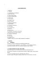
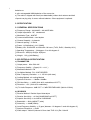
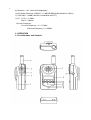
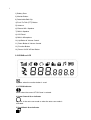
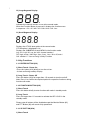
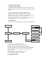
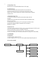
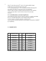
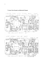
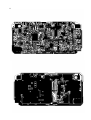
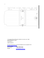
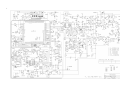
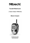
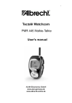
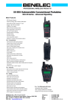
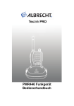
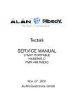
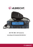
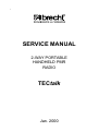
1
SERVICE MANUAL
2-WAY PORTABLE
HANDHELD PMR
RADIO
TECtalk
Jan. 2000
2
CONTENTS
1. GENERAL
1.1 General
1.2 Characteristics and features
2. SPECIFICATION
2.1 General Specification
2.2 Electrical Specification
3. OPERATION
3.1 Push buttons
3.2 ICONS on LCD
3.3 Key Functions
3.4 Setting and Operation
4. ADJUSTMENT
4.1 Frequency synthesizer
4.2 Transmitter
4.3 Transmitter test
4.4 Receiver
4.5 Receiver test
4.6 Symptoms, check point & corrections
5. DESCRIPTION OF RADIO CIRCUIT
5.1 Frequency Synthesizer
5.2 Receiver
5.3 Transmitter
6 CHANNEL DATA
7 ANNEX: CIRCUIT LAYOUTS AND SCHEMATIC DIAGRAM
1. GENERAL
1.1
GENERAL
TECtalk is a minimum sized two-way portable handheld radio.
The frequency range is 446.00625 ~ 446.09375MHz, 8 UHF operating channels
according to European PMR 446 international agreement are available.
1.2 CHARACTERISTICS AND FEATURES
a) All active devices in this radio are semiconductors and high density IC.
b) The radio is designed very compact and the weight is approximately 140g including
battery.
c) The unit is equipped with CPU HD404889 from HITACHI.
d) Power supply is designed for battery operation with 4 cells alkaline (1.5V AAA)
3
batteries or
4 cells rechargeable NiMH batteries of the same size.
e) The radio is shipped with fixed (non-detachable) rubber duck antenna and belt
clip and carrying strip. It comes without batteries. Other equipment is optional.
2. SPECIFICATION
2.1 GENERAL SPECIFICATIONS
a) Frequency Range : 446.00625 ~ 446.09375 MHz
b) Output Impedance : 50Ω unbalanced
c) Modulation Type : 8K0F3E
d) Communication Mode : semi-duplex
e) Channel Capacity : 8 channels
f) Channel spacing : 12.5 kHz
g) Power : 6.0V(alkaline), 4.8 V (NiMH)
h) Battery Life : ALKALINE: at 1000mAh >30 hours (Tx5%, Rx5%, Stand-by 90%)
i) Operating Temperature : -20 degrees C to +60 degrees C
j) Dimension : 95.5(H)x 50(W)x 26(D)mm
k) Weight : 132 g (with Battery)
2.2 ELECTRICAL SPECIFICATION
a) TRANSMITTER
1) Output power : Max. 500 mW
2) Frequency Stability : ±5 ppm(-20 ~+ 60 )
3) Modulation Method : FM
4) Oscillation Method : PLL SYNTHESIZER
5) Max. Frequency Deviation : < +/- 2.5 kHz (with tone)
6) Cooling Method : air-cooling Method
7) Spurious Emission : < -36dBm /-30dBm
8) FM Hum/Noise : > -40dB (1kHz 60% modulation,w/CCITT)
9) Distortion : < 5% (1kHz 60% modulation)
10) Tx Audio Response : 6dB /OCT +/- 3dB PRE-EMPHASIS (300Hz~2.5kHz)
b) RECEIVER
1) Receive Method : Double Super Heterodyne
2) Receive Sensitivity : < 0.28uV(20dB SINAD w/CCITT)
3) Squelch Sensitivity : 6 to 8 dB at 12dB SINAD
4) Bandwidth : > 3kHz (6dB ATT point)
5) Selectivity : < -60dB (25kHz)
6) Local Frequency Stability :+/- 5 ppm( between –20 degrees C and +60 degrees C)
7) Spurious Response : > 40dB
8) Audio output : 200mW (Internal 8 Ohms load THD 10%) Ext: 100mW
4
9) Distortion : < 5% (1kHz 60% Modulation)
10) RX Audio Response : 6dB/OCT +/- 3dB DE-EMPHASIS (300Hz to 2.5kHz)
11) S/N Ratio : < 40dB (1kHz 60% modulation w/CCITT)
12) IF : 1'st IF = 21.7MHz
2'nd IF = 450kHz
13) Local Frequency :
1st Local Frequency = fc - 21.7MHz
2nd Local Frequency = 21.25MHz
3. OPERATION
3.1 Push Buttons and Controls
5
1) Battery Door
2) Monitor Button
3) Detachable Belt Clip
4) Push-To-Talk (PTT) Button
5) Antenna
6) External Mic / Speaker
7) Built-in Speaker
8) LCD Panel
9) Built-in Microphone
10) Up Button & Volume Control
11) Down Button & Volume Control
12) Function Button
13) Power On/Off & Enter Button
3.2 ICONS on LCD
1) RSSI (Receiving Signal Strength Indicator) or TX Bar Icon
Indicates the receiving signal strength and blinks during
transmission.
2) Monitor Indicator
Appears when the monitor button is used.
3) CTCSS Indicator
Blinks when the correct CTCSS tone is entered.
4) Auto Channel Scan Indicator
Appears in the auto scan mode or when the auto scan mode is
activated.
5) Dual Watch Scan Indicator
6
Appears in dual watch scan mode or when the dual watch scan mode is
activated.
6) Key Lock Indicator
Blinks in auto lock selection mode or when the key lock is
activated.
7) VOX Indicator
Blinks in VOX selection mode or appears when VOX is activated.
8) Battery Level Indicator
Battery Level Meter indicates the remaining battery strength.
9) Power Save Display
Blinks when the power save is activated.
The rate at which the icon blinks varies with the power saving
ratio.
Fast indicates a lower power saving while slow indicates a higher
Power saving ratio.
10) Tx Indicator
Appears when a signal is being transmitted.
11) Rx Indicator
Appears when a signal is being received.
7
12) Large Segment Display
Indicates the channel number in use at the normal mode.
When the Function Button is pressed, it displays the function menu
in sequence: CH / SC / dW / UO / Udt / ALo / CAL / ton
13) Small Segment Display
Displays the CTCSS tone option at the normal mode.
CTCSS option is displayed in Hz.
Displays the SUBMENU of each MENU in the function mode.
(e.g. CH 1~69 / SC: up, dn / dW: channel number /
UO: high, off,low / Udt: 5sec, 3sec, 2sec, 1sec / ALo: off, auto /
CAL number:1-7 / ton:no-Freq) 3.3 Key Function
3.3 Key Functions
3.3.1 ENTER BUTTON (#13)
1) Short Touch - Power On
Press this button (#13) briefly to turn the unit on.
A short confirming melody will play.
2) Long Touch - Power Off
Press this button (#13) for longer than 1.5 seconds to turn the unit off.
Note: Press it to confirm the required option for respective functions during
function edit mode.
3.3-2 FUNCTION BUTTON (#12)
1) Short Touch
Press this button briefly to enter function edit mode in standby mode.
2) Long Touch
Press for longer than 1.5 seconds to activate the KEY LOCK in the
standby mode.
Please note all buttons will be disabled except the Monitor Button (#2)
and PTT Button (#4) will remain fully operational.
3.3.3 UP BUTTON (#10)
1) Short Touch
8
In the standby mode, press this button briefly to move to the next
higher main volume level.
In the function edit mode, press briefly to shift from the current
option in each submenu to the next option in the same submenu.
2) Long Touch
Pressing this button for more than 1.5 seconds will allow you to navigate
at a more rapid rate through different volume level in the standby mode
or through different menus in the function edit mode.
3.3.4 DOWN BUTTON (#11)
1) Short Touch
In the standby mode, press this button briefly to move to the next
higher main volume level.
In the function edit mode, press briefly to shift from the current
option in each submenu to the previous option in the same submenu.
2) Long Touch
Pressing this button for more than 1.5 seconds will allow you to
navigate at a more rapid rate through different volume level in the
standby mode or through different menus in the function edit mode.
3.3.5 PUSH-TO-TALK (PTT) BUTTON (#4)
Press it firmly and speak into the Built-in Microphone (#9) to transmit.
The red Tx LED Indicator at the right side of the LCD Panel (#8) will
be on.
Release it to revert to standby mode. When an incoming call is received,
the green Rx LED Indicator on the left side of the LCD Panel (#10) will
be on.
Call Tone Transmission
Press the PTT Button twice quickly to call another party on the same
channel. The word CALL and the Tx icon will appear in the display.
The user selected call ringer melody will play.
3.3.6 MONITOR BUTTON (#2)
Press it to check activity on the current channel before you try to
transmit.
Adjust the Volume Control (#10, #11) if necessary.
When you press the Monitor Button, the LCD Panel (#8) will be illuminated
with an amber color back-light and both the Tx and Rx LED Indicators will
be on.
If you press the Monitor Button during the function edit mode, you will
return to standby mode directly.
3.3.7 EXTERNAL MIC/SPEAKER (#6)
9
This jack accepts an optional headset/microphone for totally handsfree
operation.
Please refer to the user manual or Albrecht catalogue.
See also section regarding VOX SELECTION MODE.
3.4 Setting and Operation
3.4.1 BASIC CHANNEL SELECTION
In order to communicate with other PMR units, both you and the receiving party
must be on the same channel. Tectalk has 8 channels (1-8) as indicated by
the large digits in the LCD Display Panel (#8).
Before, trying to transmit on the selected channel, you should press the Monitor
Button (#2) to check the activity on that channel.
If someone is already on the selected channel, you should try another
channel which is not occupied.
To change the basic channel, in the standby mode, press the
Up Button (#10) briefly to move to the next higher main channel number.
Press the Down Button (#11) briefly to move to the next lower main channel
number.
3.4.2 CTCSS (Coded Tone Controlled Squelch System)
SUB-CHANNEL SELECTION MODE
This feature allows you to have more privacy on the main channel by using tone codes
(international numbering system 00-38) within a main channel. This enables you to
communicate with Your partners on the same main channel when all partner stations
use the same subcode. This helps to avoid congestion on the main channel and filters
out unwanted noise, static and other stations using different codes.
There are 38 CTCSS subchannels for each main channel.
To change the CTCSS subchannel,
Press the Function Button (#12) until the word cTc appears in the LCD Panel (#8).
Press the Up Button (#10) or the Down Button (#11) to choose the desired subchannel
to use. The corresponding subcode frequency will be displayed in the lower right corner.
Press the Enter Button (#13) to confirm your selection.
NOTE:
To communicate with other PMR units, they must be switched to the same
channel and CTCSS subcode. To communicate with other LPD units that do
not have subcodes, switch your unit to the same channel with the subcode
set to OFF.
3.4.3 AUTO CHANNEL SCAN MODE
This feature allows you to scan for an active channel and communicate with the party
transmitting.
10
To access the Auto Channel Scan menu, press the Function Button (#12) until the auto
channel icon blinks and SC appears in the LCD Panel (#8).
Press the Up Button (#10) or the Down Button (#11) to choose scanning up or down
from the current channel number.
Press the Enter Button (#13) to confirm your selection.
The unit will begin scanning for an active main channel. If a transmission is detected,
the Rx and RSSI icons will appear in the LCD Panel (#8).
To turn off the auto channel scan feature in the standby mode, simply press the
Function Button (#12) once.
3.4.4 DUAL WATCH SCAN MODE
This feature allows you to monitor two different channels at the same time. If you preset any priority channel other than the current channel in use, the pre-set channel will be
scanned every 0.5 second and signals you when a call is received.
To access the Dual Watch Scan menu,
Press the Function Button (#12) until the dual watch icon blinks and dW
appears in the LCD Panel (#8).
Press the Up Button (#10) or the Down Button (#11) to select the desired
channel number you wish to closely monitor.
Press the Enter Button (#13) to confirm your selection.
To turn off the dual watch feature in the standby mode, simply press the
Function Button (#12) once.
3.4.5 VOX SELECTION MODE
The Voice Activated Transmission (VOX) function allows your voice to activate
transmission automatically when the Communicator is used with an optional handsfree
mic/headset, or even with the built- in Microphone.tton (#4) without using the PTT
button.
To access the VOX Selection menu,
Press the Function Button (#12) until the VOX icon blinks and UO appears in the LCD
Panel (#8).
Press the Up Button (#10) or the Down Button (#11) to select from high, low or off. High
or low setting determines VOX response sensitivity.
Press the Enter Button (#13) to confirm your selection.
To turn off the VOX feature, enter the VOX selection mode and then select Off.
3.4.6 VOX RECOVERY TIME SELECTION MODE
11
This allows the response characteristics of the VOX function to be precisely adjusted to
suit individual needs.
To access the VOX Recovery Time Selection menu,
press the Function Button (#12) until Udt appears in the LCD Panel (#8) with the VOX
icon blinking.
Press the Up Button (#10) or the Down Button (#11) to select from 5, 3, 2 or 1 second
setting. This setting determines the delay time between transmitting and receiving.
Press the Enter Button (#13) to confirm your selection.
Please note you may need to try different VOX time settings to determine the best value
to suit your speaking habit.
To turn off the VOX feature, enter the VOX selection mode and then select Off.
3.4.7 AUTO KEY LOCK SELECTION MODE
This feature prevents accidental channel change and disturbance to the preferred
settings of the Communicator. Auto Key Lock temporarily disables the Up, Down and
Enter Buttons.
To access the Auto Key Lock Selection menu,
press the Function Button (#12) until the auto lock icon blinks and ALo appears in the
LCD panel (#8).
Press the Up Button (#10) or Down Button (#11) to select the Auto option.
Press the ENTER key to confirm your selection.
If you do not press any key for more than 15 seconds in the standby mode, all
respective keys will automatically be locked.
To turn the auto key lock on or off in standby mode, simply press and hold the Function
Button (#12) for more than 1.5 seconds.
To quickly activate the Auto Key Lock, hold the Function Button (#12) for more than 1.5
seconds.
3.4.8 CALL RINGER MELODY SELECTION MODE
This feature provides 7 user selectable call ringer melodies to alert you of a calling party.
To select your favorite Call Ringer melody,
press the Function Button (#12) until the call icon blinks and CAL appears in the LCD
panel (#8).
Press the Up Button (#10) or Down Button (#11) to preview the 7 available melodies.
Press the ENTER key to confirm your selection.
12
4. SERVICE AND ADJUSTMENT
4.1 Frequency synthesizer (PLL)
a) Open the radio, disconnect the antenna and connect apower meter
And a 50 Ohms dummy load with the internal antenna connecting point of
TECtalk.
b) Check the voltage between TP & GND in digital volt meter.
c) Then set the low channel of TECtalk the lowest frequency.
d) After pressed PTT key of TECtalk , trim VC1 for adjusting the lowest
frequency of Tx channel to DC 1.5V in the voltage of TP1.
e) After releasing the PTT key, And then check if the highest frequency
of Rx channel is within DC 1.0V in the voltage of TP,
4.2 TRANSMITTER
a) Connect EUT & measure equipment according to block diagram below.
POWER SUPPLY
MODULATION METER
OSCILLOSCOPE
AV VTVM
EUT
POWER METER
DUMMY LOAD
DISTORTION METER
SPECTRUM ANALYZER
AF OSCILLATOR
FREQUENCY COUNTER
b) Connect DC 6.0V, voltage preset to EUT.
c) Connect "power meter" & "dummy load (50 Ohms)".
d) Adjust Tx frequency according to trimming trimmer VC2.
e) Connect AF oscillator to mic terminal for conform modulation degree.
f) Adjust the frequency of AF oscillator to 1kHz and adjust AF level
should be 100mV.
g) Checking oscilloscope and modulation meter. max.
frequency deviation should be in +/- 2.5 kHz.
4.3 TRANSMITTER TEST
13
a) Output Power Test
power(6.0V DC) should be Max.500mW and in -50% range.
b) Audio Response
Connect AF oscillator to Mic terminal and then firm the audio level
that doesn't distortion the wave of oscilloscope in the frequency range,
300Hz to 3kHz. Check the audio level for 300Hz to 3kHz based on frequency
standard, 1kHz.
c) Modulation Degree Test
1) Connect AF oscillator to the MIC terminal and then adjust the level
to 100mV
2) Measure the oscilloscope wave and he point needle of modulation meter
after pressing PTT key.
3) Sweep gradually the frequency of AF oscilloscope from 300Hz to 3kHz.
4) At this time, the point needle of modulation meter should be in
the limit of +/- 2.5 kHz.
d) Spectrum Test
1) terminate antenna output with 50 Ohms and use a power attenuator of 20 dB, to avoid
harmonics generated by analyzer overload.be 20dB more.
2) observe the spectrum with pressing PTT key. The harmonics should be
less than -36/-30 dBm (with 20 dB external attenuator the reading will be –56/-30 dBm).
4.4 RECEIVER
a) Preparation
1) Adjust the power supply to DC 6.0V
2) Adjust Voltage level to 0.7Vrms( at 8 Ohms speaker output load) after power on.
b) Connection method
SSG
EUT
8 Ohms LOAD
OSCILLOSCOPE
POWER SUPPLY
AV VTVM
DISTORTION METER
IN D M T R
14
c) Signal generator Adjustment for RX sensitivity test
1) Adjust SSG to channel frequency.
2) Adjust modulation frequency, 1kHz to modulation degree, 1.5 kHz.
3) After adjusting the frequency of SSG to channel frequency, set RF level
to -47dBm.
d) Check and adjust Squelch sensitivity
1) Set the standard channel.
2) In squelch mode, SQ volume RV1 must be turned counterclockwise to open the
squelch.
3) After adjusting SSG to channel frequency, the RF level of SSG is set
so that a SINAD of 8 6dB is obtained. Turn potentiometer carefully so that
Squelch just opens at that point.
4.5 RECEIVER TEST
a) Rx sensitivity test
SSG should be adjusted to 12dB of SINAD's point needle
Observe waveform of oscilloscope at signal generator signal modulated with 1kHz
audio and 1.5 kHz frequency deviation. The 12 dB Sinad point should be reached with
an RF level of –110 to -107Bm. This is a good sensitivity.
b) Audio Distortion Test
1) SSG should be adjusted like way of point a) and RF level set to -47dBm.
2) Adjust to 0.7Vrms( at 8 Ohms load) observing audio wave form.
3) Read the needle of distortion meter (it should be less than 5% distortion).
c) Squelch Test
After RF level of SSG should be set to the lowest level, RF level should
be gradually increased until speaker makes audio sound. At this point,
check RF level(Check if the SINAD is 8 6 dB). Check that squelch will close when Level
is reduced to minimum. If not, readjust RV 1 and check again.
4.6 Symtoms, Check point & Correction
a) Diagnosis method
1) Check each switch to work well.
2) Check voltage of battery.
3) Problem whether problem comes from transmitter or receiver?
15
b) Troubleshooting
a)Transmitter
Power key is on condition but does not work.
Battery could completely be discharged.
Battery cell wrong inserted?
Contact problem between Battery and Radio?
Fail to transmit
Run out of battery or charge problem.
Fault of PTT key
Fault of Q4, Q5.
T ransmitter works but frequency is unmatched
defective frequency synthesizer.
defective X-tal (X2).
No audio modulation (Tx power and Tx frequency are normal)
Problem of microphone or mic connector.
IC U7 problem.
Tx is set when switch is on.
Tx switch problem
2) RECEIVER
Rx does not work
Speaker line open problem or connector problem.
Receiver power circuit problem.
Audio amplifier Base band IC U4 problem.
Only noise sound
U12 problem.
VCO problem.
Rx sensitivity is weak
Antenna mounting problem.
Front-End circuit problem.
Local oscillation frequency deviation.
SF1 SAW filter fail.
VCO problem.
Squelch does not work
U12 problem.
Control logic problem.
16
5. DESCRIPTION OF RADIO CIRCUIT
5.1 Frequency synthesizer
Frequency synthesizer consists of VCO, PLL IC(built in PRESCALER) and
loop filter.
a) VCO
VCO is composed of ONE VCO. Oscillation circuit takes colpitts circuit using
variable Diode. And VCO is composed of D1,Q8,Q9,C81,C75,VC1,L1,C74,C76.
VCO control voltage through loop filter adjusts frequency and microphone
signal through modulation terminal generates FM modulation.
b) PLL IC
PLL IC is adjustable IC to produce the desired frequency which VCO
provides through loop filter. It has internal counter using 21.25MHz
reference frequency to generate 6.25kHz as reference Signal. VCO frequency
from prescaled input is divided signal and compared with reference
signal phase in phase comparator. Built-in charger pump changes voltage
(until two signals are in phase) and charged voltage supplies VCO
through loop filter to produce the desired frequency.
Frequency data associated with channel goes to PLL IC by CPU
through CLOCK, DATA. PLL IC enables by strobe line of CPU.
c) Loop Filter
Loop filter is composed of R48,R49,C84,C85 and forms pulses from pin14
Into to DC and eliminates harmonic components in pulses.
It helps VCO oscillate clearly as DC voltage is supplied into Varicap.
5.2 RECEIVER
This is composed of Dual Conversion Super Heterodyne. First IF is
21.7MHz. Local oscillator frequency is lower in 1'st IF than Rx
frequency. It is called low side injection. Second IF is 450kHz. 2nd
local oscillator frequency comes to 21.25MHz.
a) Rx/Tx Conversion Circuit
Rx signal goes to Rx/Tx conversion circuit through FIXED antenna
connector, low pass filter(L5,L6,L7,C42,C43,C46,C47) and
receiver resonance circuit composed of L8,C1. When transmitting,
voltage through R25,L12,D6 supplies, D7 of receive input is short and
Tx is on condition. When PIN diode is off in condition of Rx, L8
and C1 resonate serially and make impedance matching at receiver
bandpass filter. (SF1).
17
b) Front End
Front-End has Q1 to provide a high sensitivity and low noise feature.
It employs SAW filter as band pass filter to eliminate image frequency
frequency and to produce enough pass band by Q1 input and output.
c) Mixer
Mixer has one base BFQ 67W(Q2) to feature high low noise quality.
It has RF signal through L7, L8, SF1,SF2 and Q1 RF signal from Local
oscillator mixed.
It develops 1'st IF ,21.7MHz. 1st IF goes to 1st IF amplifier Q3(KTC4080)
base through X-tal filter XF1.
IF of mixing signals is selected and enters the X-tal filter.
Output impedance of mixer is direct matched with input impedance
of X-tal filter.
Matching of filter satisfies pass bandwidth of filter, ripple
elimination within the pass band, and attenuation characteristic of stop
band. X-tal filter is composed of two pole monolithic X-tal filter,
with 8kHz of IF bandwidth. R11 is used as impedance matching with 1'st IF
Amp Q3.
d) IF AMP and Detection
1'st IF AMP Q3 supplies IF(U12) mixer input pin16 through output
resistor R13 and C21 to need gain in insertion loss of X-tal filter
and last stage circuit. Multi-use IF IC makes up of mixer IF AMP.
pin1 2'nd local frequency enter to pin 1.
It supplies mixer of internal IC. Mixer output of IC through pin3 passes
450kHz ceramic filter, supplies 2'nd IF amplifier and limits.
After 2'nd IF AMP has a process of enough gain and AM rejection,
it comes to quadrature detection. Demodulated audio signal by T1(Quad Coil)
is amplified and comes out to pin 9.
Detected audio signal through R22, VR1 and input in audio amp IC U4 through C22.
e) Squelch Circuit
Noise component of detected outputs has amplification
Squelch threshold is controlled by Resistor R18,C31,R15
f) Audio Amplifier
Demodulated audio signal enters to pin2 of U4. After above signal is amplified
in U4 the audio output for the speaker is reached at pin 5 (through C220).
5.3 Transmitter
18
When Tx starts with pressing PTT switch, VCO output amplifies through
Q4,Q5 transmits by antenna through low pass filter.
Tx RF signal produced from Tx VCO is amplified by DRIVER Q5 through C53
and entered Q4 POWER TR input terminal with final amplification.
After this stage, the signal is emitted at antenna through 50 Ohms matching
circuit to low pass filter(L7,L6,L5,C42,C43,C44,C46,C47) to eliminate
harmonics.
5.3.1 Audio Modulation and Audio Amplification
Audio signal produced by external or internal microphone is amplified and limitted
by IC U7. The output signal enters to VCO through low pass filter and
U2. Max. Frequency modulation deviation is adjusted by VR1
Audio modulation and audio amplification has preemphasis characteristic of 6dB/OCT
by U7(NJM324V).
11. CHANNEL DATA
CH
Frequency (MHz)
CH
Local Oscillator (MHz)
1
446.00625
1
424.30625
2
446.01875
2
424.31875
3
446.03215
3
424.33215
4
446.04375
4
424.34375
5
446.05625
5
424.35625
6
446.06875
6
424.36875
7
446.08125
7
424.38125
8
446.09375
8
424.39375
19
7. Annex: Circuit layouts and Schematic Diagram
20
21
© Copyright Albrecht Electronic GmbH & Jcom Ltd, Jan. 2000
Albrecht Electronic GmbH
Dovenkamp 11
22952 Lütjensee
All service documents can be downloaded for service purpose from:
http://www.albrecht-online.de
Service-Hotline:
Service-Fax:
E-mail:
(+49) 4154 849 180
(+49) 4154 849 288
[email protected]
1