1
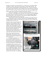
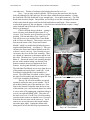
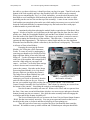
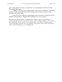
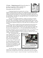
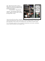
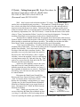
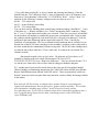
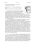
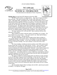
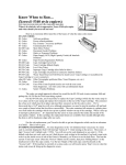
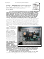
www.partsdrop.com
from 3 articles originally published in ENX Magazine.
C35 style… Taking them apart: Repair Procedures for the
Xerox CopyCentre C35/45/55, (WorkCentre) WC35/45/55,
M35/45/55, Pro35/45/55, & (DocumentCentre)
DC535/545/555.
by Britt Horvat
C35 style (DC555 shown)
If ever a series of Xerox brand machines deserved all of our attention… the C35 style
is that series. These things are wonderful. They seem to be quite reliable and they produce
stunning density in the solid areas of a copy or print. They serve all of the needs of an office
multifunction machine. They’re fast (35, 45, or 55 pages per minute) without taking up too
much space and they’re generally easy to work on. There are of course a few things which
could use some explaining and a few things which take a lot longer to do than you might
expect. So… this month lets get our hands dirty and take one of these machines apart.
Our model in this adventure is actually a DocumentCentre 555. The DC535/545/555
models look quite different from the others in the series at first glance, although internally
they’re the same engine. The C35/45/55 and the other 35/45/55 models have a curved design
for the front door which is fast becoming a trademark for the newer Xerox models. The only
complaints I hear out there are; that the machines are relatively noisy to run, that they take a
long time to power on or off, and that replacing the latches for the modules is surprisingly
time consuming. We’ll get into that later on. First lets look at some of the stuff that’s easy to
replace.
These machines are
modular… and many of the
modules are considered to be
“CRU’s” or Customer
Replaceable Units. The
Xerographic Module, the
Fuser Module, the Transfer
Corotron and the Document
Feed Head are all CRU’s.
Behind the front door, you ‘ll
find that there are a number of
pieces which can be moved
around to get modules in and
out and also to clear paper
jams. It may take a little
while to get familiar with how
everything needs to be
positioned. The pieces
Photo 1 – Inside the Front Door…
themselves; although they are
green to give you a hint, they
don’t have clear markings to tell you where they should be positioned. It can be a little bit
confusing at first. Do yourself a favor and spend a few minutes figuring out what position
each piece is supposed to be in. If you have anything out of place, the font door will not
close. Be gentle when closing the door so nothing gets damaged.
The Xerographic Module (Drum Unit) comes out by opening the front door, flipping
up a latch lever and sliding the unit out to you (see Photo 1). The latch lever cams the
www.partsdrop.com
from 3 articles originally published in ENX Magazine.
by Britt Horvat
developer unit out of the way automatically for you. When you buy a Xerographic Module
(113R608 or 113R610), it also comes with a Transfer Corona Assembly in the box. The
Transfer Corona is also designed to be replaced without any tools. It sits on a long narrow
piece called the “Short Paper Path” which is hinged at the rear end so that when you slide the
Xerographic Module out, this unit drops down. When you go to put the Xerographic Module
back in… you need to remember to raise that Short Paper Path / Transfer Assembly back up
so that it latches in the up-position just under the drum (refer to Photo 1).
The Fuser is even simpler… give it time to cool off, then open the front door, flip up
the Fuser Latch Lever and slide the fuser out the front. Piece of cake. If you are replacing the
fuser module, make sure to look over the old one to see if it’s worth rebuilding. Many of
these need only rollers, a fuser web and a new fuser connector (CRUM). Read the March
2006 article which details how the fuser comes apart.
The Developer Unit with its Toner Dispensing Assembly on top is pretty easy to get
out as well although it requires a technician. First remove the Xerographic Module (Drum
Cartridge) and put it someplace safe from light such as a black bag. Next you’ll remove the
left side panel to gain access to two
connectors. There is a main connector and a
developer bias lug to unplug (see Photo 2).
Then remove two screws from the front end
and the unit will slide out the front of the
machine. The Toner Cartridge is on the top of
the unit in the Toner Dispense Assembly. To
get the Toner Dispense Assembly off of the
Developer Unit you’d unplug the two
connectors for the two motors at the rear end
of the unit (one drives the toner dispense
auger and the other spins the toner cartridge
itself to keep the toner flowing into the
dispense auger. Then remove two screws
Photo 2 – Developer Unit Removal,
from the left side of the unit (near the rear
Connectors behind the left side cover
end). The Toner Dispense Assembly will then
slide off to the left.
We ran into an odd thing on one of the
first toner dispense problems we were
involved with. It turned out that the foam seal
from the end of the toner cartridge had come
off of the cartridge and remained lodged on
the dispense mechanism. It almost looked like
it belonged there till we looked closer and
realized what had happened. Someone must
have been rough pulling a used toner cartridge
out… leaving that piece behind. Then the new
toner cartridge could not dispense properly
because it wasn’t seating all the way in. Time
Photo 3 – Developer Unit Removal, Front End.
will tell if that will prove to be a common
scenario or if it was a fluke… an interesting
www.partsdrop.com
from 3 articles originally published in ENX Magazine.
by Britt Horvat
case either way. Thanks to Jim Intravia for bringing that one for us to see.
Now … lets go down to the Feed Rolls. All 4 trays use the same basic idea for the
feed rolls although tray 1&2 and trays 3&4 use rollers with different part numbers. Getting
the Feed Rolls off of the feed heads is easy enough to do… but requires some care. The Feed
Heads look extremely fragile. One problem you are likely to run into is damaged feed heads
which result when the paper stack hits the feed head and tears stuff apart. If the customer
overloads the paper tray, this can happen. A kit which was introduced later on puts a “ramp”
on the outboard end of the feed roll so that it is less
likely to get damaged.
If the Feed Head does get broken… getting it
out is a bit more work than the other items we’ve
covered. You’ll need to get at it from the rear of the
machine. Pull out and remove Tray 1 and Tray 2.
Take off the rear cover and the Waste Toner Bottle
with it’s Door (see Photo 4). Then remove one screw
from near the center of the “Power and Control
Module” which is a module that includes the power
supplies and Main Board… (see Photo 5). Then you
can move the Power and Control Module to the left
so that it’s out of your way. Now from the rear you
Photo 4 – Waste Toner Door Removal.
can remove the cover for the Feed Assembly. There
are a bunch of connectors to disconnect and the feed
drive belt. Then there are 5 screws from the rear (see
Photo 6) . Extract the entire Feed Assembly through
the rear of the machine taking care that the Feed
Sensor Actuators do not get caught on the Feed
Sensors. Just be gentle and take your time here…
The individual Feed Heads are set away from the rest
of the module on fragile plastic “stand-offs”. Each
Feed Head is held onto the Feed Assembly by 3
screws. The OEM Parts List which we have, spares
Photo 5 - Remove one screw to move the
the entire Feed Assembly and does not spare the Tray
Power & Control Module to your left.
1 & 2 Feed Assemblies individually.
The tray 3 & 4 Feed Assemblies are spared
separately and are the same as one another. You’ll
get at these from the rear of the machine too. First
remove the Network Controller from the lower rear
of the machine (it is a self-enclosed plastic box which
is easy to take off by unplugging it and then sliding it
over to your right and lifting it off). Then take off
the lower rear cover. For the Tray 4 Feed Assembly,
you also need to remove an internal cover (2 screws).
After that, the two come out the same way. You’ll
remove two screws (the one at the bottom and the
one at the upper right). Unplug the ribbon cable
Photo 6 – Five Screws removes the
taking notice of how the blue strip is positioned on
Tray 1 & 2 Feed Module
www.partsdrop.com
from 3 articles originally published in ENX Magazine.
by Britt Horvat
the cable so you know which way it should go when you plug it in again. Then lift a tab at the
bottom of the feed assembly and move the assembly to the left so that it can be extracted.
When you are reinstalling the Tray 3 or 4 Feed Assemblies, you need to hold down the feed
head shaft to avoid catching the feed head on the inside of the machine (the shaft is visible
protruding out the rear in a slot near the top of the assembly). A more recent version of the
feed head has an extra plastic plate on the rear which makes it necessary to use a tool to hold
down the feed head shaft (they recommend using a tiny flat head screwdriver with paper
wadded around it to protect the shaft).
I mentioned earlier that replacing the module latches required more effort than it firsts
appears. It looks at first like you could unscrew the latch pins from the front, but alas, that is
not the case. Both the Xerographic Module Latch and the Fuser Module Latch are screwed
from the inside of the frame of the machine. This means to get in there, you need to remove
the entire scanning bed from the top of the machine. This takes time… so make sure you
estimate the labor appropriately. The latches are rather fragile and they are also important.
When the fuser latch breaks (which it often does), the fuser doesn’t seat properly. This results
in all sorts of fuser related failures.
Preparing for removing the Scanner
Module, you’ll first take off the Document
Feeder. It comes off easily by unplugging it,
removing two thumb screws which secure the
hinges and then sliding it forward a little and
lifting off. Use the red transport bolt (looking
at the rear of the machine, the transport bolt is
stored in a little cubby on your upper left
corner… see Photo 7) to lock the scan carriage
so that it does not move around when you
remove the scanner. Next take out the Image
Processing Board Module (it is a big drawerlike tray which sits just below the scanner).
The Image Process Board Module has a pair
of thumb screws and then a bunch of
Photo 7 – Preparing to remove
connectors you’ll need to disconnect, then the
the Scanner Assembly.
unit will slide out the rear for you. Remove
the rear cover and the large black cooling fan with its plastic shroud. Also remove the
Control Console Assembly (the User Interface). That is done; by removing two screws from
the bottom of the console… then tilting the console up and unplugging it.
Now the Scanner Assembly can come off. Remove two screws and two spacers from
the front. Some more recent build machines also have two more screws and spacers from the
bottom (located near the rear corners). Now slide the entire assembly back to disengage the
two latches and lift the Scanner Assembly off.
The Service Manual also tells you to remove the Laser Unit (or Raster Output Scanner
/ ROS), but that is not entirely necessary. You can get an open-end wrench on the screw’s
hex-head at this point, to loosen it and then to help keep it from spinning out.
There has got to be a better way to replace the Fuser Latch and the drum cartridge
latch too! We intend to come up with a solution and I’d think anyone who puts their heads
www.partsdrop.com
from 3 articles originally published in ENX Magazine.
by Britt Horvat
into it will probably find a better way themselves (or better hardware) to make all of this
disassembly unnecessary.
I think that will have to do it for this month. There is more to talk about. Next month
maybe we’ll take out the Short Paper Path, the Registration Transport, and the Inverter
Assembly among other things.
I hope this article will help you approach this series of machines with that much more
familiarity and confidence. Happy Repairs and Happy New Year everyone !
Britt works for The Parts Drop, a company whose primary business is providing parts,
supplies and information for Xerox brand copiers, printers and fax machines. You can find
more information on their website www.partsdrop.com. If you’d like to read more about
Xerox brand office equipment, there’s a complete listing of past articles under contributing
writers on the ENX website (www.ENXMAG.com).
C35 style… Taking them apart II: Repair Procedures for
the Xerox CopyCentre C35/45/55, (WorkCentre)
WC35/45/55, M35/45/55, Pro35/45/55, &
(DocumentCentre) DC535/545/555.
C35 style (Pro55 shown)
Continuing the thread from last months article, we’ll keep
taking this wonderful machine apart (and of course, putting them back together too!). Last
month, we took out all of the easy stuff like the fuser module, Xerographic Module (drum
cartridge), Feed Rolls & Developer Unit. Then we also dug a bit deeper to replace the Tray 1
& 2 Feed Module, as well as the Tray 3 & 4 Feed Modules, the Toner Waste Bottle Door, and
the Scanner Module. Then finally, the surprisingly labor intensive, Fuser Module Latch and
the Xerographic Module Latch.
In the interest in continuing to build folks’ confidence and comfort level with this
series of machines… This month, we’ll hit on some more Removal procedures. Lets see…
what’s next? How about the Duplex Transport, the Short Paper Path (that’s the piece which
the Transfer Corona sits in), the Registration Transport, and the Inverter Module? We’ll also
talk a bit about the Registration Setup since you’ll need that when you reinstall some of these
assemblies.
By the way, there are a bunch of newer models coming down the pike which are the
same basic engine. There could be some changes to watch out for, but so far they look
extremely similar. These new models include the CopyCentre, WorkCentre, & WorkCentre
Pro: 165/175/232/238/245/255/265/275. That’s 24 new models added to the original 15. In
the interest of not “jumping the gun”, we won’t assume that the procedures and technical
information will all apply, in spite of my suspicion that there will be very few changes beyond
logic / software changes and machine speeds (the 175 & 275 are 75ppm machines for
example). I’ll need to do something of a “What’s the Difference” article once I get a chance
to learn more about the newcomers.
Ok… you will need to remove the
Duplex Transport (marked “2a” on its
green handle) before you can remove any
of the other modules addressed in this
article. This is easily accomplished…
First get the Fuser Module out, then
remove 1 screw (5.5mm Hex Drive) from
the front (See Photo 1), pull the transport
out 3 inches and disconnect its wiring
harness. Then it’ll slide out the front to
you. When you are reinstalling it… make
sure that the rail of the Duplex Transport
Photo 1– Releasing the Duplex Transport
is properly positioned on the metal
And the Registration Transport
channel (see Photo 1).
The “Short Paper Path” is the assembly which holds the Transfer Corotron (it is
marked 4b on its green handle). It also houses the vacuum transport fan and the vacuum
transport roller. It is hinged at the rear end so that it can drop down to allow the Xerographic
Module to be removed. Be gentle… this piece looks fragile. To get the Short Paper Path out;
first take out the Fuser Module, Xerographic Module, Duplex
Transport, and the Transfer Corona Assembly (push it
towards the rear and raise up the front to remove). Go to the
rear of the machine and remove the rear cover. Here you’ll
need to move the Power & Control Module to the left and a
little bit outward… It can be released from the machine by
removing one screw (see Photo 3). Next remove the rear
cover and disconnect the Transfer and Detack Leads from the
High Voltage Power Supply. The Transfer Lead (marked
Photo 2– Duplex Transport
with a “T”) goes on the right side and the Detack (marked
(Correct positioning of rail)
with a “DT”) goes to the left (See Photo 4). Free those leads
up so that you can pull
them into the machine
through the round hole in
the frame. Now go back
to the front, and pull the
two leads through the
round hole in the frame.
From inside the machine,
you’ll remove one screw
with it’s corresponding
Photo 4 – Transfer (T) &
Photo 3 – Remove 1 screw to
ground lead, from the
Detack (DT) Leads
move the Power & Control Module
lower left of the Short
Paper Path’s hinge bracket and a second
screw from the right side of the same bracket
(see photo 5). Pull the transfer and detack
leads through the hole in the machine’s frame
and disconnect the vacuum Transport Fan’s
connector.
With the Short Paper Path out, you can
access the Vacuum Transport Fan and the
Vacuum Transport Roller easily.
When you go to reinstall the Short
Paper Path, you’ll want to double check the
routing of the transfer wire and the spiral
wrapped detack wire on the hinge. When you
place the hinge back in place, make sure it is
Photo 5 – Short Paper Path Removal
pushed fully against the machine’s frame.
Install the lower left screw with its grounding wire first followed by the screw on the right
side. Double check the action of the Short Paper Path hinge… it should move smoothely as
you raise and lower the assembly. To double check your work, install the Xerographic
Module (drum ctg.) and the Transfer Corotron. Make sure that the Short Paper Path latches
up to the bottom of the Xerographic Module without having to force it. The Transfer
Corotron should be parallel with the drum when you latch the assembly up.
Next, let’s see how the Registration Transport comes out (it has “4c” marked on its
green knob). This will be necessary if you ever need to get to the Registration Roller and the
Registration Clutch. Start by taking off all of the stuff we already talked about. Also remove
the Developer Module (details are in last month’s article). Open the left door and remove 2
screws and the registration retainer bracket and the ground wire trapped beneath one of the
screws (Refer back to Photo 1). Disconnect the connector and the spade lug terminal (red) at
the front end of the assembly. Move the Registration Transport frame forward slightly and
lift it to unlock the transport from the base.
When you go to reinstall the Registration Transport, make sure that the ground wire is
reattached properly and double check for continuity between the registration / pre-registration
rollers and the machine’s ground (any uncoated metal frame will serve as a ground test point).
After any of the above items are reinstalled, check the Registration and make
adjustments if need-be. Here’s how that works. First make sure that 8.5x11 paper (or A4) is
loaded in Tray 1 with the 11 inch edge being the lead edge. Enter the Diagnostic Mode (hold
down the “#” button while then pressing the ‘Access’ button… the machine will prompt you
for a passcode… use the default: ‘1934’). Select the ‘Diagnostic Routines’ tab on the
touchscreen, then press ‘Copier Routines’, followed by ‘604 Registration Setup’. Choose
“Image Output Terminal Registration Side 1”, then “Setup All Trays”, then “Print Test
Samples” and follow the prompts. Look at the 3 test sheets which print out. The scale
marked Zone ‘D’ on the test prints shows you the Lead Edge Registration (20mm is ideal) and
Zone ‘A’ represents the setting for the “Top Edge” or Front Edge Registration” (20mm is
ideal). Press “Ok” to continue. On the screen which comes up, use the up & down arrows to
input the average measurement you see in ‘Zone A’ and ‘Zone D’ to the nearest .5mm., then
press ‘Save’. New test patterns with the corrected registration will print out. The same
process can be used to check and adjust side 2 of duplexed copies (choose “Input Output
Terminal Registration Side 2” this time).
We have one more piece to attack. The Inverter Transport which handles duplexing
and paper exit transport is the final module we’ll take out this month. You’ll need to take out
the Fuser Module, and Duplex Transport. Also remove whichever Output Device the
machine is equipped with… either the
Oscillating Catch Tray (OCT) or the Large
Capacity Stacker Stapler (LCSS). Take off the
right hand cover (2 screws). Now remove the
Inverter Support (2 screws from the front) and
the “Tie Bar” which is a metal plate from the
front frame to the rear frame (see Photo 6).
The Tie Bar is held in by 4 screws; two from
the front and two from the rear. There is a pair
of connectors to release on the Inverter Drive
Board (that board is attached to the Tie Bar).
Also disconnect Plug / Jack 49 (PJ49)
which is for the Inverter Gate Solenoid. You
Photo 6 – Inverter Transport removal - Front
can lift the Inverter Frame and move it towards
the front of the machine until the idler shafts at the rear of the unit clear their holes (see Photo
7). Once you’re certain the shafts are all of the way out, you can turn the rear end of the
Inverter to the right and remove the module through the right side of the machine.
When you reinstall the Inverter Transport, make sure the wiring harness for the
Inverter Gate Solenoid is behind the unit so that there is no chance of it getting into the paper
path. When the idler shafts are fully in,
rotate knob 3c clockwise to engage the drive
coupling and to help locate the Inverter into
the base of the machine.
That should do it! Happy Repairs
everyone… these machines look like they
will be a pleasure to work on once we all get
the hang of them. Enjoy!
Photo 7 – Inverter Transport removal - Rear
Britt works for The Parts Drop, a company whose primary business is providing parts,
supplies and information for Xerox brand copiers, printers and fax machines. You can find
more information on their website www.partsdrop.com. If you’d like to read more about
Xerox brand office equipment, there’s a complete listing of past articles under contributing
writers on the ENX website (www.ENXMAG.com).
C35 style… Taking them apart III: Repair Procedures for
the Xerox CopyCentre C35/45/55, (WorkCentre)
WC35/45/55, M35/45/55, Pro35/45/55, &
(DocumentCentre) DC535/545/555.
C35 style (Pro55 shown)
Well… there’s more work to be done on these C35 critters. The past two month’s
articles have seen detailed repair procedures… This month we’ll finish the thought. We’ll
have a look at the Main Drives Module and then catch up on a few odds and ends which I
may have missed in the previous articles. I also need to put in a small piece of the puzzle
which was missed when we covered the Status Code meanings (Oct. 2005 ENX article) and
the Memory Adjustments (Nov. 2005 ENX article). It turns out that the Status Codes which
relate to “Toner Concentration Failures” need to be reset from the diagnostics. Turning the
machine off and back on is not going to do the trick as I had first believed.
The Main Drives Module includes the Xerographic Drive Motor and a rather massive
flywheel which is mounted to the spline of the motor (it is designed to make the turning of the
drum cartridge as smooth and consistent as possible). The module also includes the Main
Drive Motor, which is responsible for driving much of the rest of the machine.
Time to get our hands dirty. To remove the Main Drives Module from these
machines takes a little effort. You’ll start by taking out the Xerographic Module (drum ctg.)
and the Fuser Module. You’ll also want to release the
Developer Unit and slide it out about 4 inches. That
procedure was covered in detail in the first article in
this series (Jan. 2007 ENX article). Here’s a quick
refresher: remove the machine’s left cover and unplug
a wiring harness on the DV Unit and a bias lug. Then
remove two screws from the front end of the DV Unit.
The unit can slide out at that point.
At the rear of the machine, remove one screw
from the Power & Control Module so that it can be
shifted towards the rear of the machine (see Image 1)
Image 1 – Remove 1 screw to
for a reminder of which screw to remove). Disconnect
move the Power & Control Module
PJ24 (Plug / Jack 24) from near the top of the Power
& Control Module.
Disconnect the Main Frame Ground Wire.
Remove the Waste Toner Full Sensor, and PJ57 (Plug
/ Jack 57) from the Waste Toner Door Switch.
Release the clip holding a wiring harness (see Image
2)(make sure you don’t trap this harness behind the
Main Drives Module when you go to put it back on
later). Disconnect PJ147, PJ148, & PJ149 from the
Main Drives Module.
Now… finally you can remove the 7 silver
Image 2 – Seven silver screws.
screws which keep the Main Drives Module in place
(see Image 2), and slide it off of its locating dowels.
If you are replacing the module, pay attention to the color of the gears. There are two
versions of the Main Drives Module based on the speed of the machine. First is the 35ppm
machine’s version which has black drive gears and then there is the 45/55ppm machine’s
version which has white drive gears.
When you are ready to reinstall the Main Drives Module, it is important that you first
go to the front of the machine and support the Short Paper Path in the “up” position (that is
the piece with the Transfer Corona Assembly on it). Use a piece of string or a long rubber
band to gently hang it from the Xerographic Latch which is directly above it.
The Service Manual also advises that you lubricate the Developer Unit support pin on
the Main Drive Module. Once the module is in place, rotate the motor by hand to engage the
drive to the inverter transport before tightening the 7 screws back up.
Removing the Flywheel from the Main Drives Module is easy enough. It is held on
by the 3 short screws located near its center. The main Xerographic Drive Gear is directly
behind the flywheel as they share the same spline.
Now, to catch up on a few things. In the
first article of this series, we went so far as to
remove the Scanner Assembly (in an effort to get
to the Fuser Latch). The ROS (Raster Output
Scanner or Laser Unit) was right there for the
picking but we didn’t need it out at that point. If
you were to need the ROS out for replacement or
cleaning, you’d follow the same procedure
mentioned to get the Scanner Module off. Then
there is one screw from the front end (see Image 3)
which holds the ROS in place. With that one
screw gone, you can slide the ROS to the rear to
Image 3 – ROS (Laser Unit) Retaining
align a cutout & lift the rear end, taking particular
Screw and Serial # Label
care not to hurt the wiring on the rear end of the
(serial number starts with the machine’s
ROS (it is very vulnerable).
speed (35, 45, or 55).
If you take the ROS out and you choose to
open it for cleaning it… just keep in mind, aside
from the 5 torx screws which hold the top cover on, you should not turn any other screws
inside the ROS. The manual says it is ok, if you are extremely gentle, to clean the mirrors
including the polygon mirrors but do not clean the laser diode itself. You can use a vacuum
inside there but beware that the mirrors and slit glass are extremely delicate and may snap if
the vacuum nozzle gets too close to them. There is a Serial # label on the bottom front end of
the ROS (visible without removing it if you take the Drum Cartridge out of the machine (see
Image 3). The first 2 digits in the ROS serial number indicates the machine speed it is
designed for (35, 45, or 55).
A simple item to remove which was overlooked previously is the Erase Lamp. There
is one screw holding the Erase Lamp support at its front end (you can see it just to the right of
the ROS retaining screw in Image 3). The Erase Lamp Assembly will pull right out once that
one screw is released.
One more thing… as promised, here are the Diagnostic memory codes (NVM codes)
which need to be reset to ‘0’ whenever a Toner Concentration Status Code comes up. This
pertains to 09-360, 09-361, 09-363 codes. You will go into diagnostic mode (hold down the
‘#’ key while then pressing the ‘A Access’ button and releasing both buttons. Enter the
default Passcode ‘1934’ and touch ‘Enter’). Once in diagnostics, select “dC Routines” and
then touch “Copier Routines" followed by "131 NVM Read / Write”. Select “Chain” ‘09’
and look for the following 3 memory settings to make sure they are set to ‘0’:
09-001 – TC Lockout Low
09-115 – Sensor Failure Lockout Flag
09-276 – TC Lockout High
You can check each by touching them on the display and then touching “Read/Write”. If any
of the three say ‘1’ then the machine is in a “Toner Concentration Fault” condition. Change
the ‘1’ to a ‘0’ on the display and confirm your selection. Then when you power off and back
on, the machine will attempt to establish the proper toner concentration ratio. Keep in mind
the condition which triggered the code in the first place will need to be addressed. Look for
problems in the toner dispensing and the connections on the DV Unit. Consider the
possibility of contamination. The Service Manual actually mentions that it would be easy to
mistake one of the DC265 toner cartridges for this machine’s and these codes would result as
the toner would then be contaminated with the wrong stuff. The DC265 toner cartridges have
a yellowish end to them while the C35 has a white end. It would be an easy mistake for a
customer to make.
That should wrap this series up for a while. The next time we hit on these, we’ll
probably be looking at the new comers (Workcentre & WC Pro 165/175,
232/238/245/255/265/275) to see “What’s the Difference”. They sure do look like the C35’s
etc. but they are faster and so there will no doubt be changes to modules and parts.
P.S. Another pair of prior articles which relate to this series are the Xerographic Module
(Drum Cartridge) reconditioning Instructions (Feb. 2006 ENX article) and the Fuser Module
Repair / Rebuild Instructions (March 2006 ENX article). These are particularly useful now
that the Connectors which reset the drum count and fuser count are finally becoming available
in the market.
Britt works for The Parts Drop, a company whose primary business is providing parts,
supplies and information for Xerox brand copiers, printers and fax machines. You can find
more information, including many of Britt’s past ENX articles on their website,
www.partsdrop.com. If you’d like to read more about Xerox brand office equipment, there’s
also a complete listing of past articles under contributing writers on the ENX website
(www.ENXMAG.com).