1
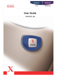
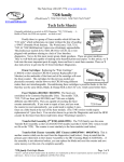
www.partsdrop.com
201-387-7776
Introducing: Xerox C123 style… Introduction & Status
Code Meanings for the Xerox CopyCentre C123, C128, &
WorkCentre M123, M128, Pro123, Pro128.
Last month we wrapped up a relatively quick look at the C118 style
(C118, C118i, M118, M118i). This month we’ll start a more in-depth
look at a series of models which look at first to have a lot in common
Xerox C123
with the C118. In fact it turns out that they are far more different than
expected. We’ll do a bit of an introduction: contrasting them with the C118’s and going over
the machine’s capabilities and supplies. Then it’ll be time to go through the Status Codes to
get some bearing on their meanings.
The model numbers which are in the C123 style include: CopyCentre C123, C128,
133, WorkCentre M123, M128, M133, Pro123, Pro128, and Pro133. I should mention that
the 133 models are not mentioned in the 2004 release of the Service Manual which was used
as the primary reference material for this article (available on Xerox’s Documentation
Website www.xdss.com under part number 701P26490 for $388.87). Considering that they
are a newer release which shares the same supply part numbers, it stands to reason that most
of what is in this article will apply to the 133’s.
The C123 style machines are being welcomed
with more warmth than the C118’s before them.
Several technicians who are selling and servicing them
reported them as being excellent machines. The
opposite was said of the C118 machines. These newcomers, I am told, are workhorses which give very little
in the way of problems. They are also rather technician
friendly. The two types of machine share a similar
appearance. They actually use the same part number
C123 style Toner Cartridge
for the drum cartridges… but that is where the similarities
pretty much dry up. The Status Codes and Diagnostic Codes
of the C123 are completely alien to the ones for the C118.
Feed components are similar in some of the trays, but the
Document Feeder parts are nothing alike. The Toner
Cartridges look similar although the C123 is considerably
larger and uses a different CRUM (Customer Replaceable
Unit Monitors… the chips which track the count and identify
the version of the cartridge). The same is true of the newest
ones… the WC-5225 style. The C123 series machines
are selling heavily out there…. So they’ll be showing up
in greater numbers than the C118’s.
There is also a Phaser printer which is related to
the C123. The Phaser 5500 is the same basic engine,
with the main difference being that there is a simpler
User Interface (no touchscreen) and no Scanner up top.
Naturally with the different User Interface, the
diagnostics will be quite different as well.
Page 1 of 11
RF CRUM
Found on Toner & Drum Ctgs.
C123 style Drum Cartridge
www.partsdrop.com
201-387-7776
The Supplies for the C123 style are very close to the C118. The Drum Cartridge is
actually identical right down to the part number (13R589). It has a yield of 60K and sells for
$199.-. The Phaser 5500 version of the Drum Cartridge (113R670) will be different
(probably just the CRUM will be different). The Toner Cartridge (6R1184) are physically
different between the C118 (6R1179), & C123 (6R1184). The Phaser 5500 (113R668) &
Phaser 5550 & the WC-5222/5225/5230 all have the same cartridge as the C123 but the
CCRUM is unique on each so you can’t freely interchange them. The CRUMS (Customer
Replaceable Unit Monitors) used on both the Drum and Toner Cartridges on these machines
are RF (Radio Frequency) types of chips… They never makes any physical electrical
connection whatsoever. Instead the machine uses radio waves of some sort to read and write
to the CRUM’s chip.
The Developer station (yep, it’s dual component, so it actually does have developer
material) is spared as part of the Drum Cartridge. They call the Drum Cartridge the
“Xero/Developer Cartridge” at times in the Service Manual. The Toner cartridges have a
small bit of Developer material mixed into them so the material remains fresh in the machine
throughout the life of the Drum Cartridge (Xero / Developer Ctg).
Now for the Status Codes. This list will have to be abbreviated somewhat because the
Service Manual acknowledges over 600 Status Codes. The general meanings of all of the
code prefixes will be represented as the first part of the code (the prefix), then a dash followed
by “xxx” to represent the second half of the code (example 010-xxx). Those generalizations
will be in bold text in the table to follow.
The book is littered with acronyms, and although there is a Glossary of Terms, many
of the acronyms which I couldn’t guess the meaning to, are not listed. It was getting
frustrating till my wife suggested that I Google the acronyms… actually found quite a few of
them. Good thinking Joann!
Status Codes / Indicators:
Code
003-xxx
003-942
005-xxx
010-xxx
010-313
010-314
010-318
010-320*
010-327*
010-398
012-xxx
016-xxx
021-xxx
024-xxx
024-910
024-911
Description
Communication Failures
Document size auto-detect failure
Document Feeder Problems
Fuser Problems
Fuser Control Thermistor failure (open Control Thermistor)
Fuser Side Thermistor failure (open Side Thermistor)
Fuser temperature did not rise quickly enough during heating cycle
Fuser Overheat (must be reset from diagnostics by resetting NVM (Non Volatile
Memory code 744-220 back to "0") *
Fuser took too long to warm up (must be reset from diagnostics by resetting NVM
(Non Volatile Memory code 744-220 back to "0") *
Fuser Fan failure
Finisher Problems
Fax Service Problems
Fax Problems
IOT (Image Output Terminal - print main logic board) - ESS (Electronic Switching
System - Network Module) Communication Errors
Tray 1 paper size mismatch (length of paper is seen as different than what the
paper size switch sees)
Tray 2 paper size mismatch (length of paper is seen as different than what the
Page 2 of 11
www.partsdrop.com
201-387-7776
024-912
024-913
024-919
024-946
024-947
024-948
024-949
024-950
024-951
024-952
024-953
024-954
024-958
024-959
024-960
024-961
024-962
024-985
025-xxx
027-xxx
033-xxx
034-xxx
035-xxx
036-xxx
041-xxx
042-323
042-325
047-xxx
047-211 /
212
047-213
047-214
047-215
047-216
047-218
061-315
061-321
061-333
062-xxx
062-277
062-300
062-310
062-360
062-371
062-380 /
386
paper size switch sees)
Tray 3 paper size mismatch (length of paper is seen as different than what the
paper size switch sees)
Tray 4 paper size mismatch (length of paper is seen as different than what the
paper size switch sees)
Face Up Catch Tray closed during copy run when paper was sent to the Face Up
Tray
Tray 1 - Tray not detected
Tray 2 - Tray not detected
Tray 3 - Tray not detected
Tray 4 - Tray not detected
Tray 1 empty
Tray 2 empty
Tray 3 empty
Tray 4 empty
MPT (Manual Paper Tray / Bypass Tray) empty
MPT (Manual Paper Tray) paper size failure
Tray 1 paper size not detected by the paper size sensor
Tray 2 paper size not detected by the paper size sensor
Tray 3 paper size not detected by the paper size sensor
Tray 4 paper size not detected by the paper size sensor
MPT (Manual Paper Tray / Bypass Tray) feed failure
Hard Drive Failures
Email Errors
Fax Control Errors
Fax Communication Problems
Fax Network Problems
Fax Paramaters Problems
NVM (Non Volatile Memory) Errors
Drum Drive Motor Failure
Main Drive Motor Failure
Options Communication Errors (Main Board to Duplex Module, Trays Module, Exit
Module, Finisher, etc.
Communication Failure with OCT (Oscillating Catch Tray)
Different Finisher detected
Communication Failure with Duplex Module (DM)
Communication Failure with Exit Board
Communication Failure with Finisher
Communication Failure with TM (Tray Module)
ROS (Raster Output Scanner - Laser Unit) laser intensity detected as being low.
ROS (Laser Unit) Motor Failure
ROS (Laser Unit) Fan Failure
Scanner Problems (IIT or Image Input Terminal)
Scanner to Document Feeder (DADF) Communication Failure
Platen Interlock is Open
Scanner Communication Error
Exposure Carriage Position Failure
Exposure Lamp Failure
Lens CCD (Charge Coupled Device… that is the piece which reads the image)
Output Error
Page 3 of 11
www.partsdrop.com
201-387-7776
062-389
062-392 /
393
071-105
071-210
071-211
072-101
072-105
072-210
072-211
073-101
073-102
073-105
073-210
073-211
074-101
074-102
074-103
074-105
074-210
074-211
075-135
077-xxx
077-101
077-103
077-104
077-106
077-129
077-130
077-131
077-300
077-301
077-305
077-307
077-308
077-309
077-329
077-900
077-901
077-902
077-904
077-905
077-906
077-907
091-401
091-912
091-913
091-914
091-915
091-916
Exposure Carriage Overrun Failure
Scanner Logic Board Failures
Tray 1 Misfeed
Tray 1 Lift Failure
Tray 1 Paper Size Switch Failure
Tray 2 Misfeed
Paper Jam from Tray 2 (sheet did not reach Registration Sensor in time)
Tray 2 Lift Failure
Tray 2 Paper Size Switch Failure
Tray 3 Misfeed
Paper Jam from Tray 3 (sheet did not reach the Registration Sensor in time)
Paper Jam from Tray 3 (sheet did not reach Tray 2 Takeaway Sensor in time)
Tray 3 Lift Failure
Tray 3 Paper Size Switch Failure
Tray 4 Misfeed
Paper Jam from Tray 4 (sheet did not reach Tray 2 Takeaway Sensor in time)
Paper Jam from Tray 4 (sheet did not reach Tray 3 Takeaway Sensor in time)
Paper Jam from Tray 4 (sheet did not reach Registration Sensor in time)
Tray 3 Lift Failure
Tray 3 Paper Size Switch Failure
Bypass Misfeed (from the MPT (Manual Paper Tray))
Paper Jams and Interlocks Open.
Paper Jam, paper not seen leaving the Registration Sensor in time
Paper Jam, paper not seen leaving the Exit Sensor in time
Paper Jam, paper seen leaving Exit Sensor earlier than expected
Paper Jam, paper not seen at Exit Sensor
Paper Jam when duplexing
Duplex Exit Sensor Jam
Duplex Wait Sensor (Duplex Feed)
Front Door Interlock Open
Left Door Interlock Open
Tray Module left hand cover interlock
Duplex Cover Open
Left Door (upper) Interlock Open.
Left Door (lower) Intlock Open
Main Motor remains on when it is supposed to be off
Paper detected sitting on the Registration Sensor
Paper detected sitting on theFuser Exit Sensor
Paper detected sitting on the Post Fuser Exit Sensor
Paper detected sitting on the Tray 2 Takeaway Sensor
Paper detected sitting on the Tray 3 Takeaway Sensor
Paper detected sitting on the Tray 4 Feed Sensor
Paper detected on the Duplex Sensor
Drum is near end of life (the count is about to expire on the CRUM)
Drum Cartridge is not present (or not seated properly)
Drum Cartridge end of life (time to replace the cartridge or at least the CRUM)
Drum Cartridge CRUM communication failure
The machine failed to write to the Drum Cartridge CRUM
Wrong Drum Cartridge type was detected (for example if you installed a European
Page 4 of 11
www.partsdrop.com
201-387-7776
092-910
093-312
093-406
093-912
093-924
093-925
093-926
102-xxx
116-xxx
121-xxx
123-xxx
124-xxx
127-xxx
133-xxx
134-xxx
202-399
cartridge in a US machine)
ATC (Automatic Toner Concentration) Sensor Failure
Toner dispense failure - density did not rise after the toner dispense motor turned
on
Low Toner condition sensed (replace cartridge soon)
Toner Cartridge is empty
Toner Cartridge CRUM communication failure
The machine failed to write to the Toner Cartridge CRUM
Wrong Toner Cartridge type was detected (for example if you installed a C118 ctg
in a C123 machine)
User Interface failures (some of them indicate failure to communicate with the ESS
or Network Controller
Printing Control Failures having mostly to do with the Hard Disk Drive, ESS
(network controller) or software
Foreign Interface problems (communications with an external device such as a
card reader or auditron)
Software problems
ROM / RAM failures
More Software related problems
More Fax Control Errors
Fax Card failures
Internal Timer failure
As noted above, some of the fuser codes need to be reset from the diagnostic mode before the
machine will attempt to warm up again. We’ll be getting into the diagnostics in the next
article, but I think that you should at least know how to use the diagnostics to get the fuser
codes to reset… Don’t want to leave you hanging!
* Resetting Fuser Codes (010-320, & 010-327) : (reset NVM code 744-220 to ‘0’)
First enter UI (User Interface) Diagnostic Mode: Hold down the ‘0’ button for 5 seconds and
then press the ‘Start’ button while still holding the ‘0’
button. The machine will prompt you for a Password.
Enter the default Access Number: ‘6789’ and press
“Confirm”. The colors on the display will be reversed to
indicate that you are now in diagnostic mode. Next press
the “Log In/Out” button on the Control Panel. Select
‘System Settings’, ‘Common’ Settings, followed by
‘Maintenance / Diagnostics’. Now you will find the main
C123 style Fuser Module
menu includes one choice called “NVM Read / Write”
(NVM is Non Volatile Memory)… Now you can enter
your “Chain-Link” code (in this case 744-220) and press ‘Confirm / Change’. The current
value will appear (if the machine is in a fuser fault condition, the value will be set to “1”).
Select the “New Value” column and input your new value (‘0’). Select “Save” and the new
number should now appear in the “Current Value” column. You can turn the power off and
back on at this point. The machine will attempt to warm up the fuser again. If the condition
which caused the fault in the first place is still happening, the Status Code will return after a
few minutes of attempting to warm up.
Page 5 of 11
www.partsdrop.com
201-387-7776
That’s a wrap. For this month anyhow… will delve into the diagnostics more in the next
article. As these machines begin needing service, I think we’ll all be ready. See you next
month!
Introducing: Xerox C123 style… (Part II) Diagnostics,
Adjustment Codes and Procedures for the Xerox CopyCentre
C123, C128, & WorkCentre M123, M128, Pro123, Pro128.
Last month we got things started with the C123 style. We did an
overview of the machine and took a peek at the Status Code meanings.
This series is getting good reviews from the folks who have been
Xerox C123
placing and repairing them, so it seems that they will prove to be worth
learning. This time, let’s hit the diagnostic memory adjustment codes. This should be kind of
interesting… I’ll have to trim the list down a bit from a rather unwieldy 1000+ codes (give or
take a few) to something which remains useful to the folks who are out there fixing them in
the field.
The diagnostic entry process is the same as the C118 machines (we covered those in a
previous article) but that’s where the diagnostic similarities end. To get into “UI Diagnostic
Mode” (UI stands for User Interface) from the powered on state, press and hold down the ‘0’
key for 5 seconds, then press the ‘Start’ button while still holding the ‘0’. The screen will
prompt you for a Password. Enter the default access number (6789) and press “Confirm”.
The colors on the display will reverse to show you that the machine is now in diagnostic
mode.
To run a Service Report, you’ll then press the “Machine Status” button on the control
panel and then select the “Billing Meters / Print Reports” tab on the display. Then press
“Print Reports / List” button followed by the “CE” button. You can print out the following
reports:
• HFSI Report (High Frequency Service Items)
• Jam Report
• Failure Report (shows the # of times each fault occurred)
• Shutdown Report (this is the Fault History which will show which Status Codes have
come up recently and when they occurred)
After running whatever reports you want to glean from the machine, turn the power off and
back on to exit the diagnostic mode.
Now, for the rest of the Diagnostics, you’ll enter Diagnostic Mode but this time, you’ll
press ‘Log In/Out’ on the control panel. You can then select “System Settings” followed by
“Common Settings” and then “Maintenance / Diagnostics” which is basically the Main Menu
for our purposes. Within that main menu you’ll find:
• NVM Read/Write: Non Volatile Memory adjustments.
• Component Control: For testing sensors, motors, solenoids, etc.
• Print Test Pattern
• Initialize NVM
Page 6 of 11
www.partsdrop.com
201-387-7776
Adjustment / Others: Includes: ‘Machine ID / Billing Data’, ‘Initialize the HFSI’
(High Frequency Service Items), ‘Adjust Toner Density’, and ‘Tray 5 (Bypass) guide
adjustment’.
If you then choose “NVM Read / Write”, you’ll be able to get to the adjustments you need to
keep the machine running right. Things like the registration, fuser temperature, etc. The
codes are 6 digit numbers separated by a hyphen between what is called the “Chain” and the
“Link” (742-027 for example). Enter the “Chain-Link” code you wish to view and select
“Confirm/Change”. The current value of your selected code will appear in the “Current
Value” column. To change the setting, you’ll then input a new number in the “New Value”
column and press “Save”.
Here is an abbreviated list of the stuff we generally all want to know… I’ve left off
anything which isn’t critical to regular maintenance and repairs (the fax codes for example are
just too lengthy to get into). For the registration adjustments, the list below includes the ones
which pertain to “plain paper” only, although the Service Manual lists multiple settings for
different heavier weight paper for each tray (there are 32 codes in the book relating to
registration and the list below shows only the 5 most commonly needed codes). The
following list should suffice to get you through most service calls.
MEMORY ADJUSTMENTS (NVM Read / Write)
•
NVM
Code
Description
700-089
HDD (Hard Disk Drive) Status
0
0-2
700-100
700-130
700-131
DHCP Mode
Sleep Mode Timer
Sleep Mode Available
Key Operator Tools Entry
Password
Default unit of measure (mm /
inch)
2
2
1
1-240
0-1
700-171
700-399
700-540
711-140
711-141
711-142
711-143
715-052
715-720
715-721
715-722
715-723
Default
Range
1 count
1 minute
Value meanings
0=Installed, 1=Failed, 2=Not
Installed
0=Manual, 4=BOOTP,
2=DHCP, 1=RARP
1-240 minutes to sleep mode
0=Disabled, 1=Enabled
11111
3
Auditron Mode
Document Feeder (DADF) Lead
Edge Registration (side 1)
Document Feeder (DADF) Lead
Edge Registration (side 2)
Document Feeder (DADF) Trail
Edge (side 1)
Document Feeder (DADF) Trail
Edge (side 2)
Platen type
Copy Density Adjustment
Copy High Density Adjustment
(darker3 setting)
Scan / Fax Density Adjustment
Scan / Fax High Density
Adjustment (darker3 setting)
0
1 = millimeters, 3 = Inches
0=Off, 1=Internal Auditron,
2=Network Accounting
0-3
129
0-214
0.0458mm
129
0-214
0.0458mm
129
0-214
0.0458mm
129
2
128
0-214
0-2
0-256
0.0458mm
128
128
0-256
0-256
128
0-256
Page 7 of 11
0=Flat Top, 1=Doc Belt, 2=CVT
www.partsdrop.com
201-387-7776
719-008
Market region
740-090
741-001
Output Configuration (where
copies are set to be delivered)
Main and Drum Motor Speed
742-009
0
0-3
0
24
0-4
0-53
0.10%
0
0-1
742-027
Enable Tray 4
Lead Edge Registration (all
trays)
33
0-66
0.2175mm
742-030
Invert timing (all trays)
33
0-66
0.435mm
742-098
Enable Face Down Tray #2
0
0-1
742-099
0
0-1
45
0-99
744-010
Enable Face Up Tray
Fuser Standby Lamp On
temperature
Fuser Standby Lamp Off
temperature
20
0-99
744-043
Fuser Ready temperature
35
0-70
744-220
Fuser Overtemperature Reset
(Resets 010-320 & 010-327
Status Codes)
0
0-5
749-523
Side Normal Erase Adjustment
8
0-18
0.254mm
749-524
Top Normal Erase Adjustment
9
0-18
0.217mm
749-527
9
0-18
0.217mm
0
0-1
33
0-66
0.2175mm
33
0-66
0.2175mm
760-003
End Normal Erase Adjustment
ATC (Auto Toner Concentration)
Sensor
Lead Edge Registration (Tray 1,
Plain Paper)
Lead Edge Registration (Tray 24, HCF, Plain Paper)
Lead Edge Registration (Bypass
/ MPT Manual Paper Tray)
33
0-66
0.2175mm
760-005
770-101
770-102
770-103
770-190
Lead Edge Registration (Duplex)
IP Address
Subnet Mask
Gateway Address
Mail Service Start / Stop
33
0.0.0.0
0.0.0.0
0.0.0.0
1
0-66
0.2175mm
770-191
770-202
Address of Mail Sender
SMTP Mail Server IP Address
NULL
0.0.0.0
744-006
752-954
760-001
760-002
Page 8 of 11
0-1
1 degree
C
1 degree
C
1 degree
C
0=FX (Fuji Xerox), 1=AP (Asia /
Pacific), XC (Xerox Canada),
XE (Xerox Europe)
0 = Face Down Tray#1, 1 =
Face Down Tray #2, 3 =
Finisher Bin1, 4 = Finisher Top
Tray
0=-2.7%, 53=2.6%
0=Disable Tray 4, 1=Disable
Tray 4
0=-7.18mm, 33=0.0mm,
66=7.18mm
0 = -14.96mm, 33 = 0mm, 66 =
14.96mm
0 = Disable Tray, 1 = Enable
Tray
0 = Disable Tray, 1 = Enable
Tray
default (45) = 175 degrees C
default (20) = 180 degrees C
default (35) = 165 degrees C
0 = Reset, 1 - 5 = Fault
condition
0 = Normal, 1 = Abnormal
0=-7.18mm, 33=0.0mm,
66=7.18mm
0=-7.18mm, 33=0.0mm,
66=7.18mm
0=-7.18mm, 33=0.0mm,
66=7.18mm
0=-7.18mm, 33=0.0mm,
66=7.18mm
0=Stop, 1=Start
enter email address
([email protected])
www.partsdrop.com
201-387-7776
770-286
770-287
780-060
780-061
780-062
780-063
POP Server User Name
POP Server Password
Tray 1 Priority
Tray 2 Priority
Tray 3 Priority
Tray 4 Priority
780-085
785-025
785-080
Drum End of Life disable
Adjust "100%" setting (98-102%)
for Fast Scan
Adjust "100%" setting (98-102%)
for Slow Scan
Edge Erase margin
790-094
790-097
Default Original Type
Default Background suppression
1
1
1-4
0-1
790-098
790-099
Default Density Adjustment
Mixed Size Default
3
0
0-6
0-1
790-122
Default Sharpness
2
0-4
790-181
Default Duplex Setting
0
0-3
790-183
Default Exit Tray
0
0-3
790-223
Default Color Mode in Scan
Default Scanning Resolution in
Scan
1
0-3
0
0-4
2
0-4
790-288
Contrast Adjust in Scan
Default Background suppression
in Scan
0
0-1
790-301
Top Edge Erase in Copy
2
0-50
1mm
790-302
Bottom Edge Erase in Copy
2
0-50
1mm
790-303
Left Edge Erase in Copy
2
0-50
1mm
790-304
Right Edge Erase in Copy
2
0-50
1mm
785-024
790-225
790-230
NULL
NULL
1
2
3
4
1-4
1-4
1-4
1-4
1
0-1
9801020
9801020
0-10
1000
1000
5
0.10%
0.10%
1mm
prioritize trays from 1 to 4
prioritize trays from 1 to 4
Prioritize trays from 1 to 4
prioritize trays from 1 to 4
1= Stop Printing, 0 = Do not
stop printing
980=98.0%, 1000=100.0%,
1020=102.0%
980=98.0%, 1000=100.0%,
1020=102.0%
0=0mm, 5=5mm, 10=10mm
1=Text, 2=Text & Photo,
3=Photo, 4=Pencil Text
0=Off, 1=On
0=Lighter3, 1=Lighter2,
2=Lighter1, 3=Normal,
4=Darker1, 5=Darker2,
6=Darker3
0=Off, 1=On
0=Sharper, 1=Sharp,
2=Normal, 3=Soft, 4=Softer
0=1 to 1 sided, 1= 1 to 2 sided,
2= 2 to 1 sided, 3= 2 to 2 sided
0= Center Tray, 1= Side Tray,
2= Finisher Tray, 3= Center
Tray2
0= Full Color, 1=Grayscale,
2=Text & Photo
0=200dpi, 1=300dpi, 2=400dpi,
3=600dpi, 4=100dpi
0=Higher, 1=High, 2=Standard,
3=Low, 4=Lower
0=Off, 1=On
0 mm to 50mm in 1mm
increments
0 mm to 50mm in 1mm
increments
0 mm to 50mm in 1mm
increments
0 mm to 50mm in 1mm
increments
Maintaining Serial Numbers in Diagnostics (clearing 124-315 codes): Maintaining a
consistent machine Serial Number in the diagnostics is important if you are replacing either
the Main Board (MCU NVM PWB) or the ESS Board (network controller). This procedure is
designed to maintain the integrity of the serial number. The machine has a redundant system
Page 9 of 11
www.partsdrop.com
201-387-7776
for assuring that if the Memory gets corrupted on one system or board, the Serial Number
remains the same for the machine after the board is replaced or re-initialized. If the boards in
the machine don’t agree about the Serial Number, the Fault Code “124-315” will show up and
this procedure will become necessary to clear the Fault.
Here’s the procedure… From the “Maintenance / Diagnostics” menu, choose
“Adjustment / Others”. Select “Machine ID / Billing Data”. You can read the Billing Meters
from here or the Serial Number as it is set on each board. To synchronize the Serial Number
data, refer to the serial number plate on the machine and select the Board which has the right
serial number (usually the one which was not replaced). Enter the Serial Number and push
“Confirm” twice. The “Set Serial Number” button will become available. Touch that button
and follow the on-screen instructions and pop-up windows to synchronize the boards’ serial
numbers.
Clearing HFSI (High Frequency Service Items) Counters (Fuser, Bias Transfer Roll, etc.).
If you enter the “Initialize HFSI Counters” option from the “Adjustment / Others” menu, you
can select individual HFSI’s such as the Fuser and Bias Transfer Roll to reset their count in
the machine’s memory. To reset one of the items, enter the “Chain-Link” code as shown on
the following table and then select “Reset Correct Value”… The screen will show “Diagnostic
Routine Completed” and the HFSI counter you chose will be reset. Here’s a list of the codes
in the HFSI:
HFSI Chain-Link Codes:
HFSI Code Description
954-807
Fuser Count
954-800
Tray 1 Feed Count
954-801
Tray 2 Feed Count
954-802
Tray 3 Feed Count
954-803
Tray 4 Feed Count
954-804
HCF (High Capacity Feeder) Feed Count
954-805
Bypass / MPT (Manual Paper Tray) Feed Count
954-808
Bias Transfer Roll
956-802
Scanner Count
956-803
Exposure Lamp On time in seconds, Lamp Life is expected at 2000 hours.
956-804
Exposure Lamp On Count (expected life is 6 million times)
956-808
Platen Opened / Closed (Platen models only)
955-806
Document Feed Count
955-807
Document Feed, single sided (simplex) Count
955-808
Document Feed, duplex mode Count
955-810
Platen Opened / Closed (Document Feeder models only)
955-829
Inverter Solenoid on Count
955-831
Document Stamp Solenoid Count
Adjust Toner Density: This function is also reachable from the “Adjustment / Others”
menu. If you select “Adjust Toner Density” and select “Measure Sensor State” and then press
‘Start’, the ATC (Automatic Toner Concentration) values will show on the display including
the ATC Target Value, ATC Output Value, ATC Result (ready or NG), and TC (Toner
Page 10 of 11
www.partsdrop.com
201-387-7776
Condition) Status (Normal, Low TC, or High TC). When “Low TC” is displayed, select
“Adjust Toner Density” and use the “UP” button to increase the number. When “High TC”
shows up, select the “DOWN” button. When the display shows “Normal” then the toner
density in the developer unit is sensed as being correct and the procedure is a success. At that
point press “Close” to exit the adjustment.
Tray 5 (Bypass) Width Guide Adjustment: This Bypass uses an analog input to recognize
what size paper the Width Guide Adjustment is set to. If the machine gets confused about the
paper size in the Bypass Tray, you can re-educate it. From the “Adjustment / Others” screen,
select “Tray 5 / Bypass Guide Adjustment”. Set the Bypass Guide on the machine to the
minimum position and select “Minimum Size Position” followed by “Start”. The display will
show “OK” or “NG”. If “NG” shows up, repeat the procedure. Once it shows “OK”, set the
Bypass Width Guide to the maximum width and then press “Maximum Position”. Again,
you are looking to see that the display shows “OK” when the machine sets up properly.
Touchscreen alignment (aligns the display with the touch-sensitivity of the touchscreen).
This is generally only needed if you replace the Touchscreen or the entire User Interface
(control console). There is supposed to be a “Touch Pen” tool hidden under the removable
panel which covers the numeric buttons on the control console, but you can use any pointed
object if you are careful not to damage the delicate surface of the touchscreen. Hold down the
‘0’, ‘1’, and ‘3’ keys while powering on the machine. A grid with intersections labeled P1 to
P9 will show on the display. Use the Touch Pen to touch the intersections of the up and down
lines P1 to P9 in sequence. Stay on the intersections for about 1 second each. Once you do
all 9 buttons, the machine will coordinate the array of values. Power the machine off and
back on. The touchscreen should now be aligned properly.
That’ll be a wrap for this month. Next month we’ll be going through the Component
Test codes and procedures to round out this series of articles which focus on the machine
itself. Later on the fusers will need a looking-at, as will the Drum Cartridges… At that time,
we’ll cover repair procedures and comparisons between different versions of the fuser
modules in the C123’s, C118’s and Phaser5500’s. See you all next month!
Britt works for The Parts Drop, a company whose primary business is providing parts,
supplies and information for Xerox brand copiers, printers and fax machines. You can find
more information, including many of Britt’s past ENX articles on their website,
www.partsdrop.com. If you’d like to read more about Xerox brand office equipment, there’s
also a complete listing of past articles under contributing writers on the ENX website
(www.ENXMAG.com).
Page 11 of 11